


BT-500
Infant Incubator
BT-500
Keep this manual for future reference
P/N : 500-ENG-OPM-EUR-R07
BT-500 Operation Manual |
1 |
Proprietary Material
Information and descriptions contained in this manual are the property of Bistos Co., Ltd. and may not be copied, reproduced, disseminated, or distributed without express written permission from Bistos Co., Ltd
Information furnished by Bistos Co., Ltd is believed to be accurate and reliable. However, no responsibility is assumed by Bistos for its use, or any infringements of patents or other rights of third parties that may result from its use. No license is granted by implication or otherwise under any patent or patent rights of Bistos.
Revision R07
Mar,2018
Copyright © Bistos Co., Ltd. 2018. All rights reserved.
7th FL., A Bldg., Woolim Lions Valley 5-cha, 302, Galmachi-ro, Jungwon-gu, Seongnam-si, Gyeonggi-do, Korea
Telephone: ++82 31 750 0340
Fax: ++82 31 750 0344
Printed in Korea
|
|
|
P/N : 500-ENG-OPM-EUR-R07 |
Bistos Co., Ltd. |
2018,03 |
BT-500 Operation Manual |
2 |
|
Table of Contents |
|
1. SAFETY ............................................................................................ |
4 |
|
1.1 |
Instructions for the Safe Operation and Use of the BT-500 ................................ |
4 |
1.2 |
Warnings ............................................................................................................. |
5 |
1.3 |
Shockh azards ................................................................................................... |
12 |
1.4 |
General precaution on environment.................................................................. |
13 |
1.5 |
Definitions and symbols ................................................................................... |
15 |
2. INTRODUCTION.......................................................................... |
16 |
|
2.1 |
General.............................................................................................................. |
16 |
2.2 |
Breif Device Description .................................................................................. |
16 |
2.3 |
Intended Use ..................................................................................................... |
16 |
2.4 |
Operating Principles.......................................................................................... |
16 |
2.5 |
Essential performance....................................................................................... |
17 |
2.6 |
Options and Accessories ................................................................................... |
17 |
2.7 Appearance of BT-500 ...................................................................................... |
19 |
|
|
2.7.1 BT-500 Front view .................................................................................................. |
19 |
|
2.7.2 BT-500 Front view Detail ....................................................................................... |
20 |
|
2.7.3 BT-500 Rear view ................................................................................................... |
20 |
|
2.7.4 BT-500 Side view.................................................................................................... |
21 |
2.8 |
Description of each part.................................................................................... |
22 |
|
2.8.1 Control shell............................................................................................................ |
22 |
|
2.8.2 Hood ....................................................................................................................... |
23 |
|
2.8.3 Mattress tray ........................................................................................................... |
23 |
|
2.8.4 Stand ....................................................................................................................... |
24 |
3. INSTALLATION & CONNECTION ........................................... |
25 |
|
3.1 |
IV pole Assembly.............................................................................................. |
26 |
|
3.1.1 IV Extenal Monitor................................................................................................ |
27 |
|
3.1.2 IV plate .................................................................................................................. |
28 |
|
3.1.3 IV ringer ploe......................................................................................................... |
29 |
3.2 Air Filter Assembly........................................................................................... |
30 |
|
3.3 |
Connection of Power and Cable........................................................................ |
31 |
|
3.3.1 Power Connection.................................................................................................. |
31 |
|
3.3.2 Cable Connection................................................................................................... |
31 |
|
3.3.3 Sensor Module Connection.................................................................................... |
32 |
3.4 |
Placement Infant ............................................................................................... |
32 |
3.5 |
Movement and Innstallation ............................................................................. |
32 |
4. OPERATION .................................................................................. |
34 |
|
4.1 |
System Start-up................................................................................................. |
34 |
4.2 LED................................................................................................................... |
36 |
|
4.3 |
Key and knob operation.................................................................................... |
37 |
|
4.3.1 Key......................................................................................................................... |
37 |
|
4.3.2 Knob ...................................................................................................................... |
37 |
4.4 |
Displays ............................................................................................................ |
38 |
4.5 |
Temperature Measurement and Control............................................................ |
40 |
|
|
|
P/N : 500-ENG-OPM-EUR-R07 |
Bistos Co., Ltd. |
2018,03 |

BT-500 Operation Manual |
3 |
|
4.6 |
Humidity Measurement and Control................................................................. |
42 |
4.7 |
O2 Measurement............................................................................................... |
43 |
4.8 |
Weighting Scale Measurement.......................................................................... |
44 |
4.9 |
SpO2 and PR(pulse rate) Measurement ............................................................ |
44 |
4.10 Menu functions ............................................................................................... |
44 |
|
4.11 Pulse Oximeter................................................................................................ |
50 |
|
4.12 External Monitor............................................................................................. |
53 |
|
4.13 Shut down ....................................................................................................... |
55 |
|
4.14 Calibration of O2 module ............................................................................... |
56 |
|
5. ALARMS......................................................................................... |
58 |
|
5.1 |
System alarms ................................................................................................... |
58 |
5.2 |
Temperature alarms........................................................................................... |
59 |
5.3 |
Humidity alarms ............................................................................................... |
61 |
5.4 |
Oxygen alarms .................................................................................................. |
61 |
5.5 |
Weighting Scale alarms..................................................................................... |
61 |
5.6 Alarm self-test................................................................................................... |
62 |
|
6. CLEANING & MAINTENANCE................................................. |
63 |
|
6.1 |
General cleaning method and precuations ........................................................ |
63 |
6.2 |
Hood ................................................................................................................. |
64 |
6.3 |
Shell, Sensor module, Scale module, Basket .................................................... |
64 |
6.4 |
Water tankt ........................................................................................................ |
64 |
6.5 |
Skin temperature sensors and SpO2 sensors..................................................... |
65 |
6.6 |
Drain of residual water...................................................................................... |
65 |
6.7 |
Regular Inspection ............................................................................................ |
66 |
6.8 |
Battery Replacement and Disposal ................................................................... |
67 |
6.9 |
Disposal of the BT-500 ..................................................................................... |
67 |
7. SPECIFICATION........................................................................... |
68 |
|
8. TROUBLESHOOTING................................................................. |
72 |
|
8.1 |
General Checking ............................................................................................. |
72 |
8.2 Alarm Message Checking ................................................................................. |
72 |
|
9. MANUFACTURER’S DECLARATION ..................................... |
75 |
|
9.1 |
Electromagnetic emissions................................................................................ |
75 |
9.2 |
Recommended separation distances between portable and mobile |
|
|
RF communications equipment and the EUT ................................................... |
75 |
9.3 |
Electromagnetic immunity................................................................................ |
76 |
WARRANTY ...................................................................................... |
78 |
|
|
|
|
P/N : 500-ENG-OPM-EUR-R07 |
Bistos Co., Ltd. |
2018,03 |

BT-500 Operation Manual |
4 |
Section 1
Safety
1.1Instructions for the Safe Operation and Use of the BT-500 Incubator
Examine the incubator and any accessories periodically to ensure that the cables, line cords and instruments do not have visible evidence of damage that may affect patient safety or performance. The recommended inspection interval is once per week or less. Do not use the incubator if there is any visible sign of damage.
Only the AC line cord supplied with the BT-500 is approved for use with the Unit.
Do not attempt to service the BT-500 incubator. Only qualified service personnel by Bistos Co., Ltd. should attempt any needed internal servicing.
The BT-500 is not specified or intended for operation during the use of defibrillators or during defibrillator discharge.
The BT-500 is not specified or intended for operation in the presence of electrosurgical equipment.
The BT-500 is not specified or intended for operation in conjunction with any other type of equipment except the specific devices that have been identified for use in this Operator’s Manual.
Perform periodic safety testing to insure proper patient safety. This should include leakage current measurement and insulation testing. The recommended testing interval is once per year.
Do not operate the BT-500 incubator if it fails to pass the power on self-test procedure.
WARNING
CAUTION
SHOCK HAZARD
Be informed that it may cause serious injury or death to the patient, property damage, material losses against the “WARNING” sign.
Be informed that it may cause no harm in life but lead to injury against the “CAUTION” sign.
Be informed that it may cause serious electrical shock to the patient or operator, property damage, material losses against the “SHOCK HAZARD” sign.
|
|
|
P/N : 500-ENG-OPM-EUR-R07 |
Bistos Co., Ltd. |
2018,03 |

BT-500 Operation Manual |
5 |
1.2Warnings
WARNING |
Thoroughly read and understand the manual prior to use of the |
|
incubator. Failure to do so could result in personal injury or |
|
equipment damage.) |
Incubator misuse may result in harm to an infant. Only properly trained personnel should use the incubator as directed by an appropriately qualified attending physician aware of currently known risks and benefits.
Use of accessories other than those listed and approved for use in this product as original or replacement items may result in increased emissions or decreased immunity.
The total electrical current leakage of all items powered through the incubator, including devices on the outlet strip, must be less than 300uA for 120V AC/ 100V AC systems and less than 500uA for 230V AC systems. Otherwise, personal injury or equipment damage could occur.
The use of accessory equipment not complying with the equivalent safety requirements of this equipment may lead to a reduced level of safety of the resulting system. Consider the use of the accessory in the patient’s vicinity and evidence that the safety certifications of the accessory have been performed in accordance with the appropriate International Electrotechnical commission (IEC) 60601-1 harmonized national standard. Personal injury or equipment damage could occur.
Devices connecting to the serial data port must be compliant with EN 60601-1-2, the EMC requirement for Medical Devices. Failure to do so could result in personal injury or equipment damage.
Medical electrical equipment needs special precautions regarding EMC and needs to be installed and put into service according to the EMC information provided in this manual. In addition, portable and mobile RF communications equipment can effect medical electrical equipment.
The equipment shall not be used adjacent to or stack with other devices unless verification of normal operation in the configuration in which it is to be used can be achieved.
Use only Bistos recommended fuel cells for proper operation. Failure to do so could result in personal injury or equipment damage.
Higher incubator relative humidity at any given temperature
|
|
|
P/N : 500-ENG-OPM-EUR-R07 |
Bistos Co., Ltd. |
2018,03 |

BT-500 Operation Manual |
6 |
decreases an infant’s evaporative heat loss, and may cause an increase in the infant temperature. Routinely monitor the infant’s rectal and/or axillary temperature according to the attending physician’s orders or Nursery Standing Orders. Failure to do so could result in personal injury.
Higher relative humidity will, at any given time, decrease an infant’s evaporative water loss, and may cause an increase in infant temperature. This effect is greatest n very low birth-weight, premature infants. The attending physician should prescribe Temperature Control mode, temperature setting, and humidity output level setting. Routinely monitor the infant’s rectal and/or axillary temperature according to the attending physician’s orders or Nursery Standing Orders. Failure to do so could result in personal injury.
Fill the reservoir to the Maximum Filing Limit line. Do not overfill. Water spillage may result, and personal injury could occur.
Use distilled water only (<10 ppm total dissolved solids). The use of sterile water is not acceptable. Equipment damage could occur.
For proper operation of the incubator, use only skin temperature probes from Bistos Co. Ltd. Using other probes could result in personal injury or equipment damage.
Never place the skin temperature probe under the infant or use it rectally. Personal injury could occur.
BT-500 cannot differentiate between an increase in core temperature with a cold skin (fever) and a low core and skin temperature (hypothermia). The temperature of the infant is monitored separately.
When in skin mode, the skin temperature probe must be in direct contact with the skin to provide accurate monitoring of the infant’s skin temperature. When in skin mode, failure to maintain direct skin contact can result in overheating. Routinely check the infant’s condition for correct sensor attachment, and feel the infant’s skin for signs of overheating.
When an x-ray is taken through the hood, the hood could show up on the x-ray as a radiolucent shadow and could result in incorrect diagnosis.
Do not use in the presence of flammable anesthetics. Personal injury or equipment damage could occur.
|
|
|
P/N : 500-ENG-OPM-EUR-R07 |
Bistos Co., Ltd. |
2018,03 |

BT-500 Operation Manual |
7 |
Keep matches, and all other sources of ignition, out of the room in which the incubator is located. Textiles, oils, and other combustibles are easily ignited and burn with great intensity in air enriched with oxygen. Personal injury or equipment damage could occur.
Small quantities of flammable agents, such as ethyls and alcohol, left in the incubator may cause a fire in connection with oxygen. Personal injury or equipment damage could occur.
A fire and explosion hazard exists when performing cleaning or maintenance procedures in an oxygen-enriched environment. Make sure that oxygen supply is turned Off and the oxygen hose to the incubator is disconnected when performing cleaning and maintenance procedures. Turn off or disconnect oxygen supplies during periods of non-use. Failure to do so could result in personal injury or equipment damage.
If it is necessary to administer oxygen in an emergency, notify the attending physician immediately. Failure to do so could result in personal injury or equipment damage.
Improper use of supplemental oxygen may be associated with serious side effects including blindness, brain damage, and death. The risks vary with each infant. The qualified attending physician should prescribe the method, the concentration, and the duration of oxygen administration.
Administration of oxygen may increase the noise level for the infant within the infant incubator.
An oxygen analyzer shall be used separately when oxygen is delivered to the infant.
Measure the oxygen concentrations to verify delivery of the prescribed oxygen concentration. Failure to do so could result in personal injury or equipment damage.
If the patient’s arterial oxygen levels cannot be maintained when the oxygen control setting is set to maximum, the attending physician should prescribe alternate means of oxygenation. Failure to do so could result in personal injury or equipment damage.
The oxygen concentration inspired by an infant does not
accurately determine the partial pressure of oxygen(pO2) in the blood. When deemed advisable by the attending physician,
measure blood pO2 by accepted clinical techniques. Failure to do so could result in personal injury or equipment damage.
|
|
|
P/N : 500-ENG-OPM-EUR-R07 |
Bistos Co., Ltd. |
2018,03 |

BT-500 Operation Manual |
8 |
Disconnect the incubator from the hospital oxygen source when oxygen is not in use. Failure to do so could result in personal injury or equipment damage.
As oxygen use increases the danger or fire, do not place auxiliary equipment that produces sparks in an incubator. Personal injury or equipment damage could occur.
Use of anesthetic agents can interfere with oxygen analyzer accuracy.
Inspect gas/oxygen service components at regular service intervals for signs of corrosion or damage. Failure to do so could result in personal injury or equipment damage.
A dirty air intake micro filter could affect performance or cause carbon dioxide(CO2) build-up. Ensure that the filter is checked on a routine basis commensurate with local conditions.
Particularly, if the unit is used in an unusually dusty environment, more frequent replacements may be necessary. Failure to do so could result in infant injury or equipment damage.
After each change of oxygen flow, allow at least 30 min to achieve new concentrations. Failure to do so could result in personal injury or equipment damage.
Compressed gas cylinders, such as oxygen cylinders, can become hazardous projectiles if the gas is released rapidly due to damage or other causes. Securely fasten the cylinder. Failure to do so could result in personal injury or equipment damage.
Oxygen levels within the incubator hood environment may be affected when the access doors or access panels are opened. Make sure all hood access door gaskets and tubing ports are properly installed. Any open gaps in the incubator hood may reduce the incubator’s internal oxygen. Personal injury could occur.
Make sure all hood access door gaskets and tubing ports are properly installed. Any open gaps in the incubator hood will reduce the incubator’s internal relative humidity. Personal injury or equipment damage could occur.
The use of infant seats, or other accessories within the incubator that can alter the airflow pattern, may affect temperature uniformity, temperature variability, the correlation of the incubator temperature reading to center mattress temperature and infant skin temperature. Personal injury could occur.
Phototherapy units located too close to the incubator may affect
|
|
|
P/N : 500-ENG-OPM-EUR-R07 |
Bistos Co., Ltd. |
2018,03 |

BT-500 Operation Manual |
9 |
hood wall temperature, incubator hood temperature, and infant skin temperature. Personal injury of equipment damage could occur.
Phototherapy lamps placed over the top of the incubator hood may interfere with upward travel of the vertical height adjustable stand. To prevent this interference, always remove the phototherapy lamp prior to positioning the stand.
If airflow passages are not kept clear of obstructions, such as blankets and stuffed animals, during clinical usage, patient safety and incubator performance may be compromised.
To avoid overheating the infant due to direct radiation, do not position the incubator in direct sunlight or under other sources of radiant heat.
Do not place surgical covers or blankets over the infant and warm air curtain or side vents simultaneously. This may cause heatinduced injury and burns.
To prevent accidental disconnection, secure all patient leads, infusion lines, and ventilator tubing to the mattress with sufficient excess length to allow for the full range of mattress height adjustment.
Only connect equipment to the serial port that complies with the relevant IEC standard; and use data cables with plastic body connectors.
Do not raise the hood at any time while the infant is in the incubator. Gain access to the infant by the access panels and access doors. Failure to do so could result in personal injury or equipment damage.
When the front access panel (or optional rear) is open, the temperature display may not accurately reflect the incubator temperature. Do not leave the front access panel (or optional rear) open longer than essential. Personal injury could occur.
Positively secure all access panel latches to avoid accidental opening, Failure to do so could result in personal injury or equipment damage.
For infant safety, do not leave the infant unattended when the access panels are open. Personal injury could occur.
Always use two people when moving the incubator and patient together. When moving the incubator within the same floor space, check that the patient is secured safely in the unit and
|
|
|
P/N : 500-ENG-OPM-EUR-R07 |
Bistos Co., Ltd. |
2018,03 |
BT-500 Operation Manual |
10 |
either remove or secure all loose system components to prevent possible patient injury or equipment damage. If the move involves varying floor heights or a complete floor level change (i.e. thresholds, ramps, elevators), remove all items either not being used or not necessary for the move, lower the VHA, IV poles and shelves to their lowest position, place all drawers in their locked state, and remove all accessories from the front and rear rail position.
Never place objects taller than the top of the wheel casters beneath the incubator stand. Placement of objects there could interfere with the stability of the vertical height adjustable stand. Personal injury of equipment damage could occur.
To avoid possible tip-over or damage to adjacent carts, IV stands, shelves, etc., keep at least a 12” (30 cm) perimeter area clear around the vertical height adjustable stand.
For optimum incubator stability, always lock all stand wheels, Do not leave the unit unattended when parking on an incline. Failure to do so could result in personal injury or equipment damage.
When raising or lowering the incubator, the operator should ensure that both equipment and appendages are clear of the unit’s travel path. Patient and incubator connections must also be checked before adjusting the incubator height. Never place any objects on top of the drawer assembly and always check before lowering the VH that there is sufficient clearance between the incubator and stand assembly. Do not raise or lower the unit while installing or removing medical gas tanks from the tank holder assembly. Failure to do so could result in personal injury of equipment damage.
The UART port is for debugging purposes only. It does not allow connections with other devices.
Prior to placing the infant in the incubator, pre-warm the incubator to the temperature prescribed by the attending physician, or according to nursing protocol.
Only one monitor shelf should be used per incubator. When using the monitor shelf, always place the monitor in the center of the shelf, ensure that the monitor fits within the border of the shelf, and avoid stacking monitors on the shelf. Personal injury or equipment damage could occur.
Attach the incubator to the stand or the vertical height adjustable stand using the bolts provided. Failure to do so could result in the incubator separating from the stand if sufficiently tilted, particularly with the hood open. Personal injury or equipment
|
|
|
P/N : 500-ENG-OPM-EUR-R07 |
Bistos Co., Ltd. |
2018,03 |

BT-500 Operation Manual |
11 |
damage could occur.
This product has been validated with the accessories and options listed in this manual and found to comply with all relevant safety and performance requirements applicable to the device. It is therefore the responsibility of that person or organization who makes an unauthorized modification, or incorporates an unapproved attachment to the device, to ensure that the system still complies with those requirements.
A pulse oximeter should NOT be used as an apnea monitor
Pulse rate measurement is based on the optical detection of a peripheral flow pulse and therefore may not detect certain arrhythmias. The pulse oximeter should not be used as a replacement or substitute for ECG based arrhythmia analysis.
A pulse oximeter is an early warning device. Use lab co-oximeter to completely understand the patient’s condition.
Do not use the MS board pulse oximeter in the presence of flammable anesthetics or other flammable substance in combination with air, oxygen enriched environments, or nitrous oxide.
Do not remove the monitor cover except to replace the battery. An operator may only perform maintenance procedures specifically described in this manual. Refer servicing to Masimo in repair of this equipment.
Leakage current must not exceed 100 microamperes; measure when an external device is connected to the serial port.
Do not use Masimo oximetry sensors during MRI scanning as it could potentially cause burns.
Inaccurate measurements may be caused by incorrect application or use.
Inaccurate measurements may be caused by significant levels of dysfunctional hemoglobin (HbCO or MetHb).
Inaccurate measurements may be caused by intravascular dyes such as indocyanine green or methylene blue.
Inaccurate measurements or loss of pulse signal may be caused by excessive illumination.
Inaccurate measurements may be caused by excessive patient
|
|
|
P/N : 500-ENG-OPM-EUR-R07 |
Bistos Co., Ltd. |
2018,03 |

BT-500 Operation Manual |
12 |
movement.
Inaccurate measurements may be caused by venous pulsation.
Inaccurate measurements or loss of pulse signal may be caused by placement of a sensor on an extremity with a blood pressure cuff, arterial catheter or intravascular line.
The MS board pulse oximeter can be used during defibrillation, but the readings may be inaccurate for a short time.
Loss of pulse signal can occur when the sensor is too tight.
Loss of pulse signal can occur when the patient has hypotension, severe vasoconstriction, severe anemia, or hypothermia.
Loss of pulse signal can occur when there is arterial occlusion proximal to the sensor.
Loss of pulse signal can occur when the patient is in cardiac arrest or is in shock.
Use only Masimo sensors for SpO2 measurements.
Tissue damage can occur due to incorrect placement of sensor.
1.3Shock hazards
SHOCK HAZARD
Unplug the unit from its power source prior to cleaning or maintenance. For units equipped with an uninterruptible power supply(UPS) system, also remove the battery pack prior to cleaning or maintenance. Failure to do so could result in personal injury or equipment damage.
Some chemical cleaning agents may be conductive and leave a residue that may permit a build-up of conductive dust or dirt. Do not allow cleaning agents to contact electrical components, and do not spray cleaning solutions onto any of these surfaces. Personal injury or equipment damage could occur.
To ensure grounding reliability, plug the AC power cord only into a properly grounded 3-wire hospital-grade or hospital-use outlet. Do not use extension cords. If any doubt exists as to the grounding connection, do not operate the equipment. Personal injury or equipment damage could occur.
Do not expose the unit to excessive moisture that would allow for liquid pooling. Personal injury or equipment damage could occur.
|
|
|
P/N : 500-ENG-OPM-EUR-R07 |
Bistos Co., Ltd. |
2018,03 |
BT-500 Operation Manual |
13 |
Due to the risk of electrical shock hazard, only qualified personnel with appropriate service documentation should service the unit.
Batteries can present a risk of electric shock. The following precautions should be taken when working on batteries: remove watches, rings or other metal objects; use tools with insulated handles.
The total power of all equipment connected to the convenience outlet strip on the pedestal / stand must me within the electrical requirements shown on the rear of the pedestal / stand. Otherwise, personal injury or equipment damage could occur.
Make sure the Building power source is compatible with the electrical specifications shown on the column of the pedestal / stand and on the incubator. Failure to do so could result in personal injury or equipment damage.
To prevent equipment damage or accidental power disconnections, do not plug an incubator power cord directly to an AC wall socket when the incubator is mounted on a pedestal /stand. Always provide power to the incubator by using the power cord coming directly from the pedestal /stand.
1.4General precaution on environment
Do not keep or operate the equipment under the environment listed below.
|
Avoid placing in an area |
|
Avoid exposure to |
|
exposed to moisture. Do |
|
|
|
not touch the equipment |
|
direct sunlight |
|
with wet hand. |
|
|
|
|
|
|
|
Avoid placing in an area |
|
|
|
where there is a high |
|
|
|
variation of temperature. |
|
|
|
Operating temperature |
|
Avoid in the vicinity |
|
ranges from 20°C to |
|
of Electric heater |
|
30°C. Operating |
|
|
|
humidity ranges from 0% |
|
|
|
to 95%. |
|
|
|
|
|
|
|
Avoid placing in an area |
|
Avoid placing in an |
|
where there is an |
|
area where there is an |
|
excessive humidity rise |
|
excessive shock or |
|
or ventilation problem. |
|
vibration. |
|
|
|
|
|
|
|
P/N : 500-ENG-OPM-EUR-R07 |
Bistos Co., Ltd. |
2018,03 |
|
BT-500 Operation Manual |
14 |
|
|
||||||
|
|
|
|
|
|
|
|
|
||
|
|
|
|
Avoid placing in an area |
|
|
Avoid dust and |
|
||
|
|
|
|
where chemicals are |
|
|
especially metal |
|
||
|
|
|
|
stored or where there is |
|
|
material into the |
|
||
|
|
|
|
in danger of gas leakage. |
|
|
equipment. |
|
||
|
|
|
|
|
|
|
|
|
||
|
|
|
|
Do not disjoint or |
|
|
Power off when the |
|||
|
|
|
|
disassemble the |
|
|
equipment is not fully |
|
||
|
|
|
|
equipment. |
|
|
installed. |
|
||
|
|
|
|
BISTOS Co., Ltd. does |
|
|
Otherwise, the |
|
||
|
|
|
|
not take responsibility of |
|
|
equipment could be |
|
||
|
|
|
|
it. |
|
|
|
damaged. |
|
|
|
1.5 Definitions and symbols |
|
|
|
||||||
|
|
|
|
|
|
|
|
|
|
|
|
|
Symbol |
|
|
Description |
|
|
|
||
|
|
|
Used to identify safety information. |
|
|
|
||||
|
|
|
Be well-known this information thoroughly before using BT-500. |
|
|
|||||
|
|
|
During the operation, do not disconnect any cable. |
|
|
|
||||
|
|
|
Indicate the warning for hot surface. |
|
|
|
||||
|
|
|
|
|
|
|
|
|
|
|
|
|
|
Type BF Applied part |
|
|
|
||||
|
|
|
|
|
|
|
|
|
||
|
|
|
Refer to operation manual. Read manual before placing the device. |
|
|
|||||
|
|
|
|
|
|
|
|
|
||
|
|
|
Skin temperature sensor #1, to be connected to infant’s abdomen for baby |
|
|
|||||
|
|
|
(controlled) mode |
|
|
|
||||
|
|
|
Skin temperature sensor #2, to be connected to other than infant abdomen |
|
|
|||||
|
|
|
|
|
|
|
|
|
||
|
|
IPX0 |
IPX0 Non-protected against ingress of water with harmful effects. |
|
|
|||||
|
|
(Device) |
|
|
|
|||||
|
|
|
|
|
|
|||||
|
|
IPX1 |
IPX1 Protected against the vertically dripping water |
|
|
|
||||
|
|
(Skin temperature sensor_2EA) |
|
|
|
|||||
|
|
|
|
|
|
|||||
|
|
IPX2 |
IPX2 Protected against the dripping water |
|
|
|
||||
|
|
(SpO2 |
sensor) |
|
|
|
||||
|
|
|
|
|
|
|||||
|
|
IPX6 |
IPX6 Protected against the powerful jetting |
|
|
|
||||
|
|
(Foot switch_2EA) |
|
|
|
|||||
|
|
|
|
|
|
|||||
|
|
|
Indicates the weight limit |
|
|
|
||||
|
|
|
|
|
|
|
|
|
|
|
|
|
|
This symbol indicates the manufacturer. |
|
|
|
||||
|
|
|
|
|
|
|
|
|
|
|
|
|
|
This symbol indicates the serial number of the device. |
|
|
|
||||
|
|
|
|
|
|
|
|
|
||
|
|
|
This symbol indicates the authorized representative in the European |
|
|
|||||
|
|
|
Community of manufacturer. |
|
|
|
||||
|
|
|
|
|
|
|
|
|
|
|
|
|
|
P/N : 500-ENG-OPM-EUR-R07 |
Bistos Co., Ltd. |
2018,03 |

BT-500 Operation Manual |
15 |
This symbol indicates to keep the device dry.
This symbol indicates to keep the correct upright position on the transport package.
This symbol indicates the device is fragile.
This symbol indicates the temperature limitation for operation, transport and storage.
This symbol indicates the humidity limitation for operation, transport and storage.
This symbol indicates the packing material is recyclable.
External Signal IN/OUT Port
This symbol indicates the compliance with the essential requirements and provisions of the Medical Device Directive 93/42/EEC as amended by 2007/47/EEC.
This symbol indicates to not dispose the device together with unsorted municipal waste(for EU only). The solid bar symbol indicates that mains adapter is put on the market after 13 August 2005.
|
|
|
P/N : 500-ENG-OPM-EUR-R07 |
Bistos Co., Ltd. |
2018,03 |
BT-500 Operation Manual |
16 |
Section 2
Introduction
2.1 General
This chapter provides a general description of the BT-500 infant incubator including.
Brief Device Description
Product Features
Model Configurations
2.2Brief Device Description
A mains electricity (AC-powered) unit designed to provide an enclosed controlled environment to maintain appropriate temperature and humidity levels mainly for premature infants and other newborns who cannot effectively regulate their body temperature. It typically consists of a clear removable plastic hood with a mattress. It typically includes a means to warm the infant such as providing heated air; temperature controls that work automatically either by measuring the air temperature or through a temperature sensor attached to the infant skin; and humidity controls. The device is intended to use in a hospital.
2.3 Intended Use
BT-500 is an infant incubator for non-invasively measuring and showing graphically humidity, air temperature, skin temperature, O2 Module, weight and SpO2. This data is intended to aid the maintaining life of a premature baby or a precocious baby under 2kgs. This device is for use only by trained medical personnel located in hospital. Also this device can be used in the all departments of the hospital which offers a neonatal care service such as NICU(Neonatal Intensive Care Unit), special nursery unit and pediatrics.
2.4 Operating Principles
-Air and skin temperature measurement and Control: Internal cartridge heater raises the temperature. The infant environmental temperature value is determined by air a skin temperature that is measured by the sensor module. Through the main fan, the air is circulated within the hood and adjusts the temperature.
-Humidity measurement and control: The steam of humidity module vaporizes the water particles. It Adjust the humidity mixed with air within the hood. Sterilized by heating the
water to 100 .
-O2 Module(Optional): It is available to control the oxygen concentration in the hood when putting the module option of oxygen concentration.
-SpO2 measurement (Optional): The probe sensor is wear at the end of an infant’s finger. By measuring the intensity of reflected light, depending on the concentration of dissolved oxygen in the blood determines the oxygen saturation.
|
|
|
P/N : 500-ENG-OPM-EUR-R07 |
Bistos Co., Ltd. |
2018,03 |
BT-500 Operation Manual |
17 |
- Pulse rate measurement(SpO2): During the heart beats, the infrared light is from the light source.
It is on the arteriole, such as fingers. The intensity of the light is reflected to the sensor is measured.
2.5Essential performance
Air temperature measurement and incubator air temperature control.
Skin temperature measurement and infant Skin temperature control.
Humidity measurement and control inside the incubator.
An alarm occurs if the difference between the set temperature and the control temperature is more than a certain level.
System must remain in a safe condition acc. IEC 60601-1, IEC 60601-2-19
WARNING Do not use the skin temperature control on babies who are in shock or who have high temperatures
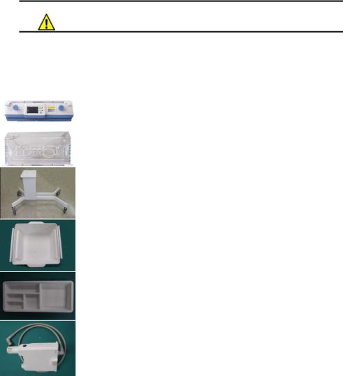
2.6 Options and Accessories
Picture |
|
Name |
|
Description |
|
Qty |
|
|
Control shell |
|
Hold up the hood and be composed |
|
|
|
|
|
with instruments and parts that control |
|
1ea |
|
|
|
(Standard) |
|
|
||
|
|
|
the temperature and humidity |
|
|
|
|
|
|
|
|
|
|
|
|
|
|
|
|
|
|
|
Hood |
|
Made of double framed clear acrylic |
|
|
|
|
|
panel to watch inside, and to minimize |
|
1ea |
|
|
|
(Standard) |
|
|
||
|
|
|
heat loss |
|
|
|
|
|
|
|
|
|
|
|
|
|
|
|
|
|
|
|
Fixed Stand |
|
Movable incubator cradle with wheels |
|
1ea |
|
|
(Standard) |
|
|
||
|
|
|
|
|
|
|
|
|
|
|
|
|
|
|
|
Basket |
|
Storage of medical equipment and |
|
1ea |
|
|
(Optional) |
|
items which infant needs |
|
|
|
|
|
|
|
||
|
|
|
|
|
|
|
|
|
Basket Partition |
|
Partition of Basket |
|
1ea |
|
|
(Optional) |
|
|
||
|
|
|
|
|
|
|
|
|
|
|
|
|
|
|
|
Sensor module |
|
Measures temperature and humidity |
|
|
|
|
|
inside the hood and infant’s body |
|
1ea |
|
|
|
(Standard) |
|
|
||
|
|
|
temperature |
|
|
|
|
|
|
|
|
|
|
|
|
|
|
|
|
|
|
|
|
P/N : 500-ENG-OPM-EUR-R07 |
Bistos Co., Ltd. |
2018,03 |

|
BT-500 Operation Manual |
|
18 |
|
|
|
|
|
|
|
|
Mattress tray |
Baby desk with X-ray tray |
1ea |
|
|
(Standard) |
||
|
|
|
|
|
|
|
|
|
|
|
|
mattress |
Accommodate infant stably with |
1ea |
|
|
(Standard) |
bouncy mattress |
|
|
|
|
||
|
|
|
|
|
|
|
Skin |
|
|
|
|
temperature |
Measures infant’s skin temperature |
2ea |
|
|
sensor |
||
|
|
|
|
|
|
|
(Standard) |
|
|
|
|
|
|
|
|
|
IV-pole |
IV hanger. |
1ea |
|
|
(Optional) |
||
|
|
|
|
|
|
|
|
|
|
|
|
AC power code |
AC Power cord(AC Power cord for |
1ea |
|
|
(Standard) |
operating the equipment) |
|
|
|
|
||
|
|
|
|
|
|
|
External LCD |
Displays measured values from the |
1ea |
|
|
Monitor |
control and video of infant inside the |
|
|
|
(Optional) |
hood. |
|
|
|
|
|
|
|
|
CCD Camera |
Takes video of infant inside the hood |
1ea |
|
|
(Optional) |
||
|
|
|
|
|
|
|
|
|
|
|
|
Masimo SpO2 |
|
|
|
|
sensor probe |
Measures infant’s SpO2 |
1ea |
|
|
(Optional) |
|
|
|
|
|
|
|
|
|
Masimo |
|
|
|
|
Extension for |
Extend sensor cable |
1ea |
|
|
SpO2 sensor |
||
|
|
|
|
|
|
|
(Optional) |
|
|
|
|
|
|
|
|
|
IV plate |
Plate to place items which infant needs |
1ea |
|
|
(Optional) |
||
|
|
|
|
|
|
|
|
|
|
|
|
Shelf |
Plate to place items which infant needs |
1ea |
|
|
(Optional) |
||
|
|
|
|
|
|
|
|
|
|
|
|
|
P/N : 500-ENG-OPM-EUR-R07 |
Bistos Co., Ltd. |
2018,03 |
|
BT-500 Operation Manual |
|
19 |
|
|
|
|
|
|
|
|
Lift Stand |
Movable incubator cradle with wheels |
1ea |
|
|
(VHAVariable Height Adjustable) |
||
|
|
(Optional) |
||
|
|
|
|
|
|
|
|
|
|
|
|
Weighting |
Measures Infant’s weight |
1ea |
|
|
Scale |
||
|
|
(Optional) |
|
|
|
|
|
|
|
Notes;
*The built-in air filter requires periodic replacement to maintain clean air periodic replacement of the pads according to the maintenance schedule is recommended.
**Oxygen control module is also available as an optional component.
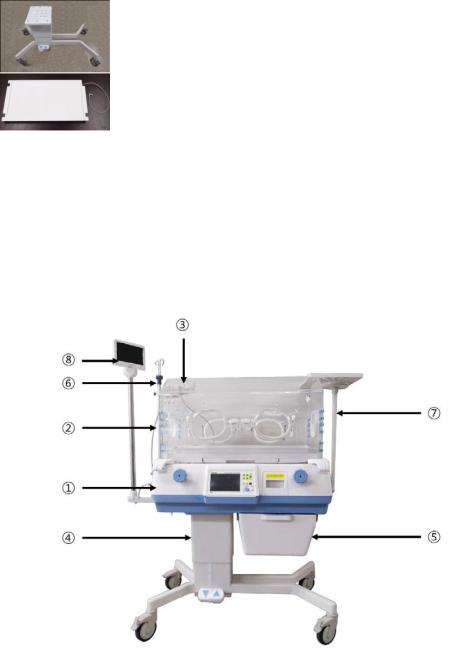
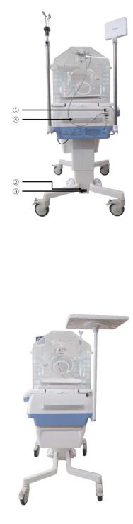
2.7Appearance of BT-500
2.7.1BT-500 Front View
Figure 2-1. BT-500 Front view
Control Shell |
Hood |
Sensor module |
Moving Stand |
Basket |
IV pole |
IV plate |
External monitor |
|
|
|
P/N : 500-ENG-OPM-EUR-R07 |
Bistos Co., Ltd. |
2018,03 |
BT-500 Operation Manual |
20 |
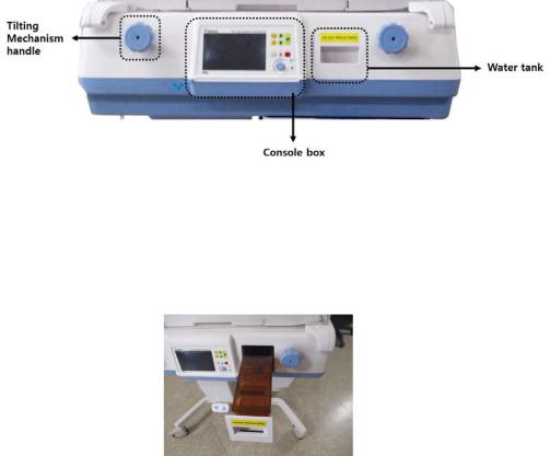
2.7.2 BT-500 Front View Detail
Figure 2-2. BT-500 Front view details
Console box |
Water tank draw |
Tilting mechanism handle |
Hood handle |
Front access door |
Baby desk with X-RAY Tray |
Weighing scale |
Compatible mattress |
2.7.3 BT-500 Rear view |
|
Figure 2-3. BT-500 Rear view
Rear Access Door |
AC power cord & Connector |
|
|
|
P/N : 500-ENG-OPM-EUR-R07 |
Bistos Co., Ltd. |
2018,03 |
BT-500 Operation Manual |
21 |
2.7.4 BT-500 Side view
Figure 2-4. BT-500 Left view
Sensor Module, SpO2 sensor & External Communication portMain power switch
Main power AC connectorIncubator handle
Figure 2-5. BT-500 Right view
|
|
|
P/N : 500-ENG-OPM-EUR-R07 |
Bistos Co., Ltd. |
2018,03 |
BT-500 Operation Manual |
22 |
2.8 Description of each part
BT-500 is composed with several parts. The control shell is the part which controls the entire device. To measure the infant’s environment, the sensor module is needed. The hood is used to protect an infant from the external environment and maintain the internal environment of hood to best condition.
2.8.1 Control shell
The control shell part consists of console box and water tank.
Figure 2-6. Control Shell
The water tank has a 1 Liter capacity. The reservoir permits visual inspection of the water level. It is located in a drawer in the front of the shell. When the drawer is closed and the latching handle is engaged, the reservoir is connected to manifold.
For more information about how to clean, see "Chapter 6 cleanliness and maintenance”
Figure 2-7. Water Tank
|
|
|
P/N : 500-ENG-OPM-EUR-R07 |
Bistos Co., Ltd. |
2018,03 |

BT-500 Operation Manual |
23 |
2.8.2 Hood
The hood of BT-500 is an acrylic material. There is Access door in the front, rear and both sides of hood.
Figure 2-8. Hood front view & Access door / side function
Warning |
To prevent accidental disconnection, secure all patient leads, infusion |
|
lines, and ventilator tubing to the mattress with sufficient excess length |
|
to allow for the full range of mattress height adjustment. |
|
|
2.8.3Mattress tray
a.Rotate the pawl latches, and open the front access panel.
b.Pivot the front access panel to the full open position (hanging straight down).
c.Slide out the mattress tray to the fully extended position (up to 22cm).
d.Carefully lean on the mattress tray to ensure it is properly supported and provides a firm infant platform.
e.Return the mattress tray.
f.Close the front access panel, and rotate both latches until they are fully engaged.
Max. to 220mm Weight limit : under 20kg
|
|
|
P/N : 500-ENG-OPM-EUR-R07 |
Bistos Co., Ltd. |
2018,03 |
 Loading...