


BT-250
Fetal Doppler
Operation Manual
BT-250
Keep this manual for future reference
P/N: 250-ENG-OPM-EUR-R07
BT-250 Operation Manual |
1 |
Proprietary Material
Information and descriptions contained in this manual are the property of Bistos Co., Ltd. and may not be copied, reproduced, disseminated, or distributed without express written permission from Bistos Co., Ltd.
Information furnished by Bistos Co., Ltd is believed to be accurate and reliable. However, no responsibility is assumed by Bistos for its use, or any infringements of patents or other rights of third parties that may result from its use. No license is granted by implication or otherwise under any patent or patent rights of Bistos Co., Ltd.
The information contained herein is subjects to change without notice.
Prepared by: Bistos Co., LTD.
7th FL., A Bldg., Woolim Lions Valley 5-cha, 302, Galmachi-ro, Jungwon-gu, Seongnam-si, Gyeonggi-do, Korea
Telephone: +82 31 750 0340
Fax: +82 31 750 0344
Revision 07
Printed in Korea
Copyright © Bistos Corporation 2018. All rights reserved.
|
|
|
P/N: 250-ENG-OPM-EUR-R07 |
Bistos Co., Ltd. |
2018,06 |
BT-250 Operation Manual |
2 |
Table of Contents
1.·System basics·············································································3
1.1Device description and Intended Use····························································3
1.2Options and Accessories················································································3
1.3 |
Description of Front Panel |
···········································································4 |
1.4 |
Description of Side Panel |
·············································································4 |
1.5 |
Description of Rear Panel |
············································································5 |
2. |
·Preparing to use ·······································································6 |
|||||
|
2.1 |
Place to use·····································································································6 |
||||
|
2.2 |
AC/DC adapter and Transducer connection ·················································6 |
||||
|
2.3 |
Factory Default Setting ·················································································7 |
||||
|
2.4 |
Understanding the BT-250 Display Screen ····················································7 |
||||
|
2.5 |
Button description ························································································9 |
||||
|
2.6 |
BT-250 Control Knob ·····················································································10 |
||||
|
2.7 |
Data Saving |
···································································································11 |
|||
|
2.8 |
Trend Mode (Data Tracing Mode) ································································11 |
||||
3. |
·Monitoring fetal heart rate ························································13 |
|||||
4. |
·Cleaning and disinfection |
·························································15 |
||||
|
4.1 |
Monitor |
·········································································································15 |
|||
|
4.2 |
Transducer |
····································································································15 |
|||
5. |
·Trouble shooting and maintenance |
··········································17 |
||||
|
5.1 |
Transducer |
····································································································17 |
|||
|
5.2 |
Battery Disposal and Handling ······································································17 |
||||
|
5.3 |
Maintenance ·································································································17 |
||||
6. |
·Safety and regulatory information |
············································18 |
||||
|
6.1 |
Warnings |
·······································································································18 |
|||
|
6.2 |
Cautions |
········································································································20 |
|||
|
6.3 |
General precaution on environment ····························································22 |
||||
|
6.4 |
Symbols |
·········································································································23 |
|||
|
6.5 |
Compliance to the standards |
········································································24 |
|||
6.6Guidance and manufacturer’s declaration – Electromagnetic emissions·······25
6.7Guidance and manufacturer’s declaration – electromagnetic immunity ·····25
6.8Recommended separation distances between portable and mobile RF
communications equipment and the BT-250 ················································28
7.·Specifications·············································································29 Product Guarantee ·······································································30
|
|
|
P/N: 250-ENG-OPM-EUR-R07 |
Bistos Co., Ltd. |
2018,06 |
BT-250 Operation Manual |
3 |
1System basics
1.1 Device description & Intended Use
The BT-250 is a desktop fetal Doppler that measures the fetal heart rate, which is displayed on a LCD, and outputs the fetal heart sound through built-in speaker. This device is for use only by trained medical personnel.
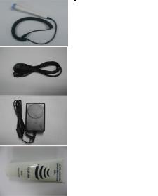
1.2 Options and Accessories
Accessory |
Name |
Description |
|
Doppler |
Ultrasound transducer for measuring |
|
FHR |
|
|
transducer |
|
|
IPX7 : Waterproof |
|
|
(1ea) |
|
|
(1 meter of water for up to 30 minutes.) |
|
|
|
|
|
Power cord |
AC power cord |
|
(1ea) |
|
|
|
|
|
|
|
|
Power adaptor |
AC/DC power adaptor |
|
Input : AC100~240 V[50/60 Hz] |
|
|
(1ea) |
|
|
Output : DC 9V, 2.0A |
|
|
|
|
|
|
|
|
Ultrasound gel |
Ultrasound transmission gel |
|
(1ea) |
|
|
|
|
|
|
|
|
Table 1.1. BT-250 Accessories |
|
|
|
|
P/N: 250-ENG-OPM-EUR-R07 |
Bistos Co., Ltd. |
2018,06 |

BT-250 Operation Manual |
4 |
1.3 Description of the Front Panel
Fig. 1.1 BT-250 Front Panel
Power Indicating LED ( AC: Green / |
Battery: Orange) |
Power On/Off Button |
|
Control knob |
|
Mode change button |
|
Save On/Off button |
|
Trend mode Button |
|
Event mark |
|
TFT-Color LCD |
|
1.4 Description of the Side Panel |
|
|
|
|
|
|
|
|
|||
Fig. 1.2 Left Panel |
Fig. 1.3 Right Panel |
|||
Earphone jack connector
Doppler transducer connectorDoppler transducer holder
|
|
|
P/N: 250-ENG-OPM-EUR-R07 |
Bistos Co., Ltd. |
2018,06 |
BT-250 Operation Manual |
5 |
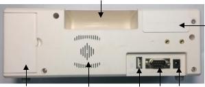
1.5 Description of the Rear Panel
Fig. 1.4 Rear Panel
Grip
Battery compartment
AC/DC adaptor connectorRS-232C port
USB port
Built-in speaker
Doppler transducer holder
|
|
|
P/N: 250-ENG-OPM-EUR-R07 |
Bistos Co., Ltd. |
2018,06 |
BT-250 Operation Manual |
6 |
2 Preparing to use
2.1 Place to use
Certain strong electromagnetic fields can interfere with the ultrasound transducer and cause a false heart rate reading. This interference is rare, and usually found in the vicinity of large machinery. In order to avoid the possibility of these interfering signals being analyzed as fetal heart rates, the following procedure should be followed whenever the monitor is to be used in a new location, or if it is known that electrical machinery is being operated in the vicinity.
After connecting the ultrasound Doppler transducer, turn on the monitor and observe the heart rate indications on the screen for 30 seconds while no signal input applied to the transducer surface. Intermittent display of random heart rates is acceptable. However, if there is a constant display of a heart rate lasting more than 5 seconds, this is an indication that there is a source of electromagnetic interference in the vicinity. The following steps should be taken to determine if it is possible to use the monitor in this environment.
Move all line cords and line-powered equipment at least 6 feet (1.8 meter) away from the BT-250. Check for extension cords running behind or under the bed and equipment in adjacent rooms. If the artifact heart rate indication ceases, the monitor may be used normally.
Remove the line cord from the monitor’s power supply. If the artifact heart rate indication ceases, the monitor may be used normally.
If these measures do not result in cessation of the artifact heart rate, the monitor cannot be safely used in this environment.
2.2 AC/DC adaptor & Transducer Connection
Connect the power cord which supplied by Bistos Co., Ltd. to power outlet and power adapter receptacle. Connect the adapter plug to the BT-250 AC/DC adaptor connector as shown in Figure 2.1. Turn on the BT-250 by pressing down the power ON/OFF button about 2 seconds.
Connect the Doppler transducer cable to BT-250 as shown in the figure below.
|
|
|
P/N: 250-ENG-OPM-EUR-R07 |
Bistos Co., Ltd. |
2018,06 |

BT-250 Operation Manual |
7 |
Fig. 2.1 Power adaptor and Transducer Connection
2.3 Factory Default Setting
To enter the factory setting mode, turn on BT-250 by press down the power ON/OFF button for about 2 seconds while press down the control knob simultaneously. In factory setting mode, all configuration parameters are initialized to factory setting value. The initial factory setting values of each parameter are as below;
|
|
Setting parameter |
|
Factory default value |
|
|||||
|
|
Monitoring Mode |
|
Number Mode |
||||||
|
|
Graph Area |
30~240 |
|
|
|||||
|
|
Auto Shunt Down |
5 |
|
|
|||||
|
|
Language |
|
English |
||||||
|
|
Start Volume |
3 |
|
|
|||||
2.4 Understanding the BT-250 Display Screen |
||||||||||
Mode frame |
|
|
|
|
|
|
Patient ID frame |
|||
|
|
|
|
|
|
|||||
|
|
|
|
|
|
|
||||
FHR frame |
|
|
|
|
|
|
|
|||
|
|
|
|
|
|
|||||
|
|
|
|
|
|
|
|
|
|
|
FHR graph frame
Date/Time |
|
|
|
|
|
|
|
Status frame |
|
|
|||||||
|
|
|
|
|
|
|
||
frame |
|
|
|
|
|
|
|
|
Fig. 2.2 Main Monitoring Screen – Graph Mode
|
|
|
P/N: 250-ENG-OPM-EUR-R07 |
Bistos Co., Ltd. |
2018,06 |
BT-250 Operation Manual |
8 |
Mode frame |
|
|
|
|
|
Patient ID frame |
|
|
|
|
|
FHR frame
Date/Time |
|
|
|
|
|
|
Status frame |
|
|
|
|||||
frame |
|
|
|
|
|
|
|
|
|
|
|
|
|
||
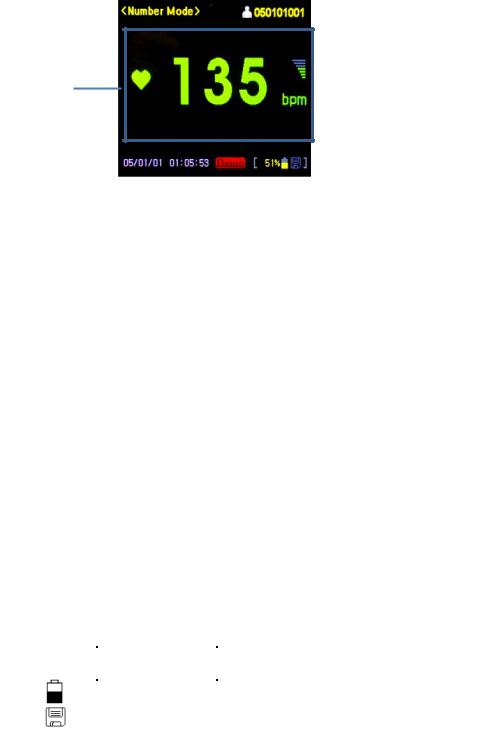
Fig. 2.3 Main Monitoring Screen – Number Mode
To change the monitoring mode between “Number Mode” and “Graph Mode”, press the [MODE] button.
2.4.1 Mode frame
The mode frame shows the current mode. There are monitoring mode (Number and Graph), setup mode and trend mode.
2.4.2 Heart Rate frame (FHR frame)
The heart rate (FHR) frame displays the fetal heart rate with a heart icon and current speaker volume setting. The heart icon blinks at the measured heart rate interval. The solid heart icon blinks when a valid rate is present and only the outline of heart icon blinks when a measured rate is unstable or weak.
The volume icon indicates the current speaker volume setting for the fetal echo sounds.
2.4.3 Heart Rate Graph frame (FHR Graph frame)
The Heart Rate (FHR) Graph frame displays a graphical representation of the fetal heart rate. The vertical scale is labeled corresponding to the recorder paper (30 to 240 BMP).
2.4.4 Status frame
This frame shows battery status and data saving status.
Symbol |
Name |
Description |
|
|
|
|
Battery Status Icon |
Indicates the battery residual quantity |
|
|
|
|
Save Icon |
Indicates the data saving status |
|
|
|
|
|
|
P/N: 250-ENG-OPM-EUR-R07 |
Bistos Co., Ltd. |
2018,06 |

BT-250 Operation Manual |
9 |
When alarm occurs, alarm status is shown below.
Symbol |
Name |
Description |
|
|
|
|
Low Battery Alarm |
Blinking until AC/DC adapter is |
|
Icon |
connected. |
2.4.5 Patient ID frame
This flame displays the patient identification number. The BT-250 uses time and date information to generate the part of ID number (6 digits). The last 3 digits used for the individual patient ID. Default ID number is YYMMDD001 when YYMMDD is the current date information. To change the individual ID number (3 digits) enter [Setup mode] by pressing control knob button. (Refer to ‘4.4 BT250 Control Knob’ section)
2.4.6 Time and Date
This frame shows the current time and date saved. These settings can be changed as needed. (Refer to ‘4.4 BT-250 Control Knob’ section)
2.5 Button description
There are 5 buttons located on the front panel. The operation of the buttons is summarized below.
|
CAUTION |
Never use sharp or pointed objects to operate the front- |
|
|
|
panel buttons |
|
|
|
|
|
|
|
|
|
|
Symbol |
Description |
|
|
|
|
|
|
|
Turns power on or off. |
|
|
|
|
|
|
MODE |
Display mode Change [ Graph Mode ↔ Number Mode] |
|
|
|
|
|
|
SAVE |
Start and stop the save function. |
|
|
|
|
|
|
|
To enter into or exit from Trend mode. The trend frames |
|
|
TREND |
shows historical patient data and the control knob |
|
|
|
provides navigation capability. |
|
|
E.MARK |
Marking event |
|
|
|
|
|
|
|
|
P/N: 250-ENG-OPM-EUR-R07 |
Bistos Co., Ltd. |
2018,06 |
 Loading...