

Biostar TP43D2-A7, TP45D2-A7 Owner's Manual

TP45D2-A7/TP43D2-A7 Setup Manual
FCC Information and Copyright
This equipment has been tested and found to comply with the limits of a Class
B digital device, pursuant to Part 15 of the FCC Rules. These limits are designed
to provide reasonable protection against harmful interference in a residential
installation. This equipment generates, uses, and can radiate radio frequency
energy and, if not installed and used in accordance with the instructions, may
cause harmful interference to radio communications. There is no guarantee
that interference will not occur in a particular installation.
The vendor makes no representations or warranties with respect to the
contents here and specially disclaims any implied warranties of merchantability
or fitness for any purpose. Further the vendor reserves the right to revise this
publication and to make changes to the contents here without obligation to
notify any party beforehand.
Duplication of this publication, in part or in whole, is not allowed without first
obtaining the vendor’s approval in writing.
The content of this user’s manual is subject to be changed without notice and
we will not be responsible for any mistakes found in this user’s manual. All the
brand and product names are trademarks of their respective companies.

Table of Contents
Chapter 1: Introduction ............................................................ 1
1.1 Before You Start......................................................................................... 1
1.2 Package Checklist..................................................................................... 1
1.3 Motherboard Features.............................................................................. 2
1.4 Re ar Panel Connectors.............................................................................. 3
1.5 Motherboard Layout................................................................................. 4
Chapter 2: Hardware Installation ............................................. 5
2.1 Installing Central Processing Unit (CPU) ............................................... 5
2.2 FAN Headers .............................................................................................. 7
2.3 Installing System Memory ........................................................................ 8
2.4 Connectors and Slots................................................................................ 10
Chapter 3: Headers & Jumpers Setup ..................................... 12
3.1 How to Setup Jumpers............................................................................. 12
3.2 Detail Settings .......................................................................................... 12
Chapter 4: T-Series BIOS & Software ..................................... 20
4.1 T-Series BIOS............................................................................................. 20
4.2 T-Series Software...................................................................................... 28
Chapter 5: Useful Help ............................................................ 37
5.1 Driver Installation Note.......................................................................... 37
5.2 Extra Information.................................................................................... 38
5.3 AMI BIOS Beep Code............................................................................... 39
5.4 Troubleshooting....................................................................................... 40
Appendencies: SPEC In Other Language ................................ 42
German.................................................................................................................. 42
France .................................................................................................................... 44
Italian ..................................................................................................................... 46
Spanish ................................................................................................................... 48
Portuguese ............................................................................................................ 50
Polish...................................................................................................................... 52
Russian ................................................................................................................... 54
Arabic..................................................................................................................... 56
Japane se ................................................................................................................ 58

CHAPTER 1: INTRODUCTION
TP45D2-A7/TP43D2-A7
1.1 B
EFORE YOU START
Thank you for choosing our product. Before you start installing the
motherboard, please make sure you follow the instructions below:
Prepare a dry and stable working environment with
sufficient lighting.
Always disconnect the computer from power outlet
before operation.
Before you take the motherboard out from anti-static
bag, ground yourself properly by touching any safely
grounded appliance, or use grounded wrist strap to
remove the static charge.
Avoid touching the components on motherboard or the
rear side of the board unless necessary. Hold the board
on the edge, do not try to bend or flex the board.
Do not leave any unfastened small parts inside the
case after installation. Loose parts will cause short
circuits which may damage the equipment.
Keep the computer from dangerous area, such as heat
source, humid air and water.
1.2 PACKAGE CHECKLIST
HDD Cable X 1
Serial ATA Cable X 2
Rear I/O Panel for ATX Case X 1
User’s Manual X 1
Fully Setup Driver CD X 1
FDD Cable X 1 (optional)
USB 2.0 Cable X1 (optional)
Serial ATA Power Cable X 1 (optional)
Note : The package contents may differ by area or your motherboard version.
1
Motherboard Manual
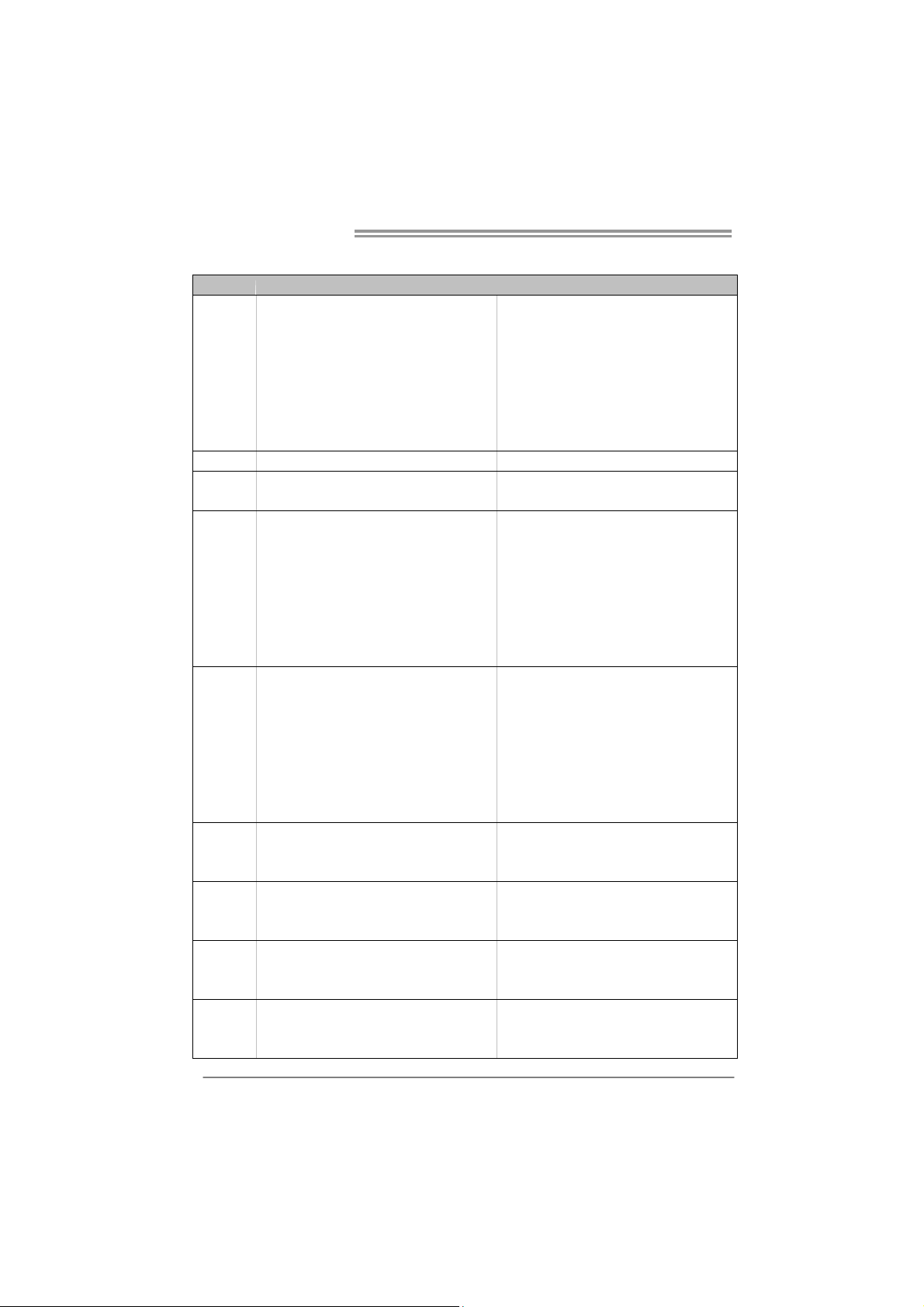
1.3 MOTHERBOARD FEATURES
TP45D2- A7 TP43D2- A7
LGA 775
Intel Core2Duo / Core2Quad /
Pent iu m Dua l-Co re / C eler on Dual- Cor e /
CPU
FSB Support 800 / 1066 / 1333 / 1600 MHz Support 800 / 1066 / 1333 / 1600 MHz
Chipset
Super I/O
Main
Memory
IDE
SATA 2
LAN
Sound
Codec
Celeron 4xx processor
Supports Execute Disable Bit / Enh anc ed Intel
SpeedStep® / Intel Ar chitecture-64 / Ext ended
Memory 64 Technology / Virtualization
Technology
Intel P45
Int e l IC H1 0
ITE 8718F
Prov ides t he most commonly used legacy Super
I/O functionality.
Low Pin Count Interface
En vironm ent C ontro l in itiat ives ,
Hardware Monitor Controller
Fan Sp eed Controller
ITE's "S mart Guard ian " funct ion
DIMM Slots x 4
Each DIMM supports 256MB / 512MB / 1GB /
2GB DDR2
Max Memory Capicity 8GB
Dual Cha nn el Mode DDR2 me mory mod u le
Supports DDR2 1066 / 800 / 667
Register ed D IMM and ECC D IMM is not
supported
JMicro JMB368
Ultra DMA 33 / 66 / 100 / 133 Bus Master Mode
supports PIO Mode 0~4
Integrated Serial ATA Controller
Data transfer rates up to 3.0 Gb/s.
SATA Vers ion 2.0 sp ecification co mplian t
Realtek RTL 8111C
10 / 100 Mb/s / 1Gb/s auto negotiation
Half / Full duplex capability
ALC662
5.1 channels audio out
High Definition Audio
LGA 775
Intel Core2Duo / Core2Quad /
Pent iu m Dua l-Co re / C eler on Dual- Cor e /
Celeron 4xx processor
Supports Execute Disable Bit / Enh anc ed Intel
SpeedStep® / Intel Ar chitecture-64 / Ext ended
Memory 64 Technology / Virtualization
Technology
Intel P43
Int e l IC H1 0
ITE 8718F
Prov ides t he most commonly used legacy Super
I/O functionality.
Low Pin Count Interface
En vironm ent C ontro l in itiat ives ,
Hardware Monitor Controller
Fan Sp eed Controller
ITE's "S mart Guard ian " funct ion
DIMM Slots x 4
Each DIMM supports 256MB / 512MB / 1GB /
2GB DDR2
Max Memory Capicity 8GB
Dual Cha nn el Mode DDR2 me mory mod u le
Supports DDR2 1066 / 800 / 667
Register ed D IMM and ECC D IMM is not
supported
JMicro JMB368
Ultra DMA 33 / 66 / 100 / 133 Bus Master Mode
supports PIO Mode 0~4
Integrated Serial ATA Controller
Data transfer rates up to 3.0 Gb/s.
SATA Vers ion 2.0 sp ecification co mplian t
Realtek RTL 8111C
10 / 100 Mb/s / 1Gb/s auto negotiation
Half / Full duplex capability
ALC662
5.1 channels audio out
High Definition Audio
2
TP45D2-A7/TP43D2-A7
TP45D2- A7 TP43D2- A7
PCI slot x3 PCI slot x3
Slots
On Board
Connector
Back Panel
I/O
Board Size 220 (W) x 305 (L) mm 220 (W) x 305 (L) mm
OS Support
PCI Express Gen2 x 16 slot x1 PCI Express Gen2 x 16 slot x1
PCI Express x 1 slot x2 PCI Express x 1 slot x2
Floppy connecto r x1 Floppy connect or x1
Printer Po rt Connector x1 Pr inter Port Connector x1
Serial port Connector x1 Serial port Connector x1
IDE Co nnect or x1 IDE Con n ecto r x 1
SATA Connector x6 SATA Connector x6
Front Panel Connector x1 Front Panel Connector x1
Front Audio Connector x1 Front Audio Connector x1
CD-in Connector x1 CD-in Connector x1
CPU Fan header x1 CPU Fan header x1
System Fan head er x2 System Fan h ead er x2
Clear CMOS header x1 Clear C MOS header x1
USB connector x3 USB connector x3
Power Connector (24pin) x1 Power Connector (24p in) x1
Power Connector (4pin) x2 Power Connector (4pin) x2
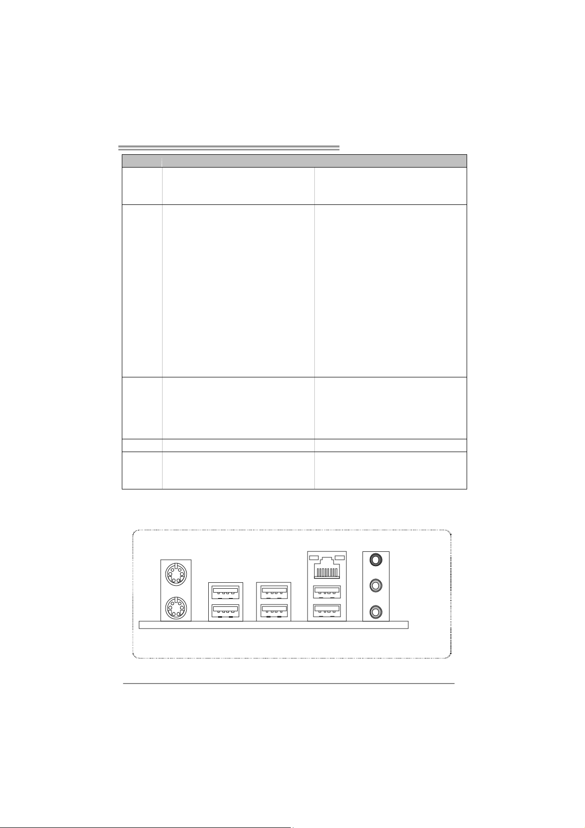
PS/2 Keyboard x1
PS/2 Mouse x1
LAN port x1
USB Port x6
Audio Jack x3
Windows 2000 / XP / VISTA
Biostar Reserves the right to add or remove
support for any OS with or without notice
PS/2 Keyboard x1
PS/2 Mouse x1
LAN port x1
USB Port x6
Audio Jack x3
Windows 2000 / XP / VISTA
Biostar Reserves the right to add or remove
support for any OS with or without notice
1.4 REAR PANEL CONNECTORS
PS/2
Mouse
PS/2
Keyboard
USBX2
USBX2 USBX2
LAN
Line In/
Surround
Line Out
Mic In 1/
Bass/ Center
3
Motherboard Manual
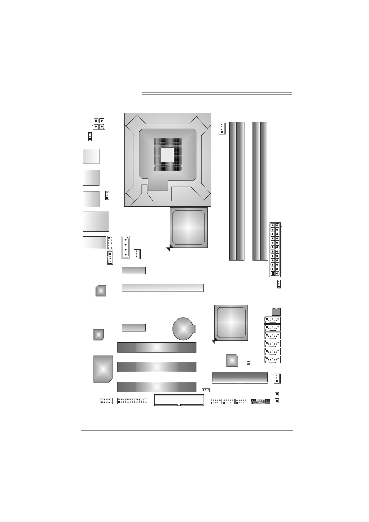
1.5 MOTHERBOARD LAYOUT
JATXPWR2
JKBV 1
JKBMS1
JUSB2
JUSB1
JRJ45USB1
JAUDIO1
JUSBV1
JAUD IO F1
LAN
JCDIN1
J1
PEX1_1
JSFA N2
LGA775
CPU 1
P45/P43
PEX16_1
Intel
JCFAN1
DDR2_A 1
DDR2_B 1
DDR2_A 2
DDR2_B 2
JATX PW R1
JCMOS1
4
CODEC
Super
I/O
JC OM1
Note: represents the 1■
PEX1_2
JPR NT1
PCI1
PCI2
PCI3
BAT1
FDD1
st
pin.
JUSBV2
ICH10
JUSB3
Intel
IDE
JUSB4
IDE1
JUSB5
LED_D1
LE D_ D2
SATA1
SATA2
SATA3
SATA4
SATA5
SATA6
JPANEL1
BIOS
JSFA N1
RSTSW2
PWRSW1
TP45D2-A7/TP43D2-A7
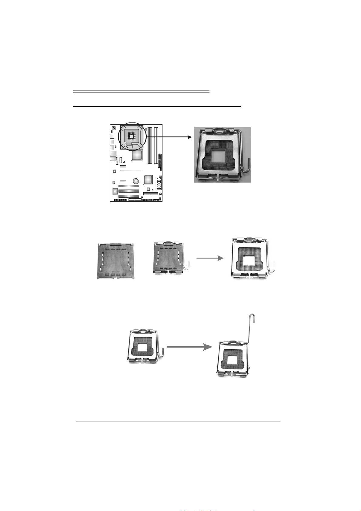
CHAPTER 2: HARDWARE INSTALLATION
2.1 I
NSTALLING CENTRAL PROCESSING UNIT (CPU)
Special Notice:
Remove Pin Cap before installation, and make good preservation
for future use. When the CPU is removed, cover the Pin Cap on the
empty socket to ensure pin legs won’t be damaged.
Pin Cap
Step 1: Pull the socket locking lever out from the socket and then raise
the lever up to a 90-degree angle.
5

Motherboard Manual
Step 2: Look for the triangular cut edge on socket, and the golden dot on
CPU should point forwards this triangular cut edge. The CPU will
fit only in the correct orientation.
Step 2-1:
Step 2-2:
Step 3: Hold the CPU down firmly, and then lower the lever to locked
position to complete the installation.
Step 4: Put the CPU Fan and heatsink assembly on the CPU and buck le it
on the retention frame. Connect the CPU FAN power cable into
the JCFAN1. This completes the installation.
6
TP45D2-A7/TP43D2-A7
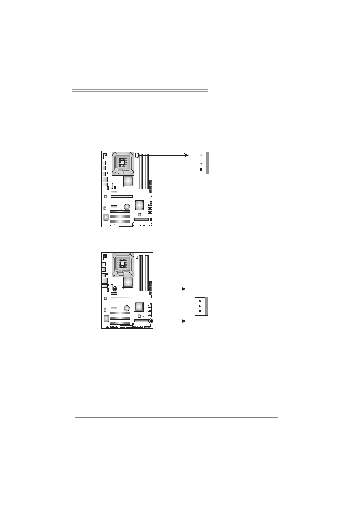
2.2 FAN HEADERS
These fan headers support cooling-fans built in the computer. The fan
cable and connector may be different according to the fan manufacturer.
Connect the fan cable to the connector while matching the black wire to
pin#1.
JCFAN1: CPU Fan Header
4
1
JSFAN1/JSFAN2: System Fan Headers
JSFAN2
3
1
Pin
Assignment
1 Ground
2 +12V
3
FAN RPM r ate
sense
4 Smart Fan
Control
Pin
Assignment
1 Ground
2 +12V
3 FAN RPM rate
sense
JSFAN1
Note:
The JSFAN1/JSFAN2 support 3-pin head connectors, and the JCFAN1 supports 4-pin
head connector. When connecting with wires onto connectors, please note that the red
wire is the positive and should be connected to pin#2, and the black wire is Ground and
should be co nnected to GND.
7
Motherboard Manual
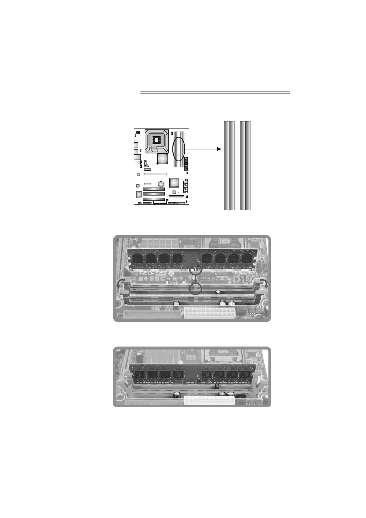
2.3 INSTALLING SYSTEM MEMORY
A. Memory Modules
DDR2 _A1
DDR2 _B1
DDR2 _A2
DDR2 _B2
1. Unlock a DIMM slot by pressing the retaining clips outward. Align a
DIMM on the slot such that the notch on the DIMM matches the
break on the Slot.
2. Insert the DIMM vertically and firmly into the slot until the retaining
chip snap back in place and the DIMM is properly seated.
8
TP45D2-A7/TP43D2-A7
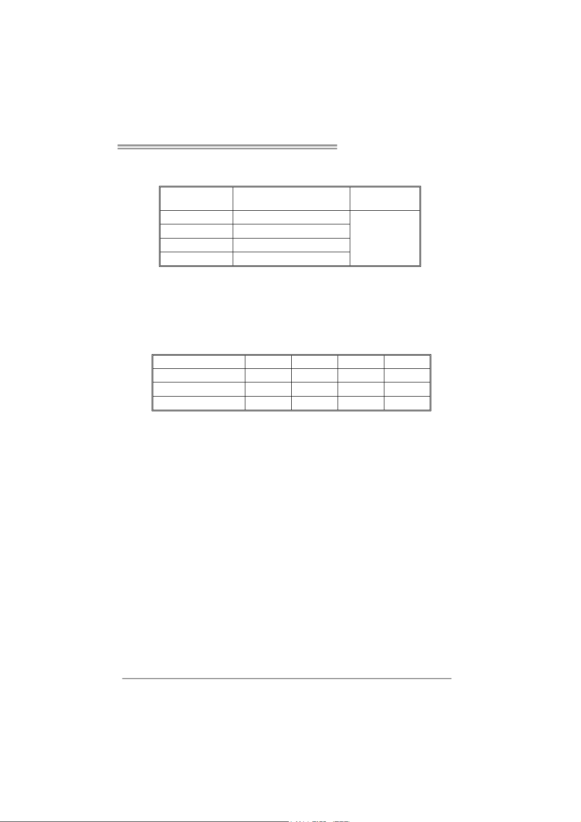
B. Memory Capacity
DIMM Socket
Location
DDR2_A1 256MB/512MB/1GB/2GB
DDR2_A2 256MB/512MB/1GB/2GB
DDR2_B1 256MB/512MB/1GB/2GB
DDR2_B2 256MB/512MB/1GB/2GB
DDR2 Module
Total Mem o ry
Size
Max is 8GB.
C. Dual Channel Memory installation
To trigger the Dual Channel function of the motherboard, the memory module
must meet the following requirements:
Install memory module of the same density in pairs, shown in the following
table.
Dual Channel Status
Enabled O X O X
Enabled X O X O
Enabled O O O O
(O means memory installed, X means memory not installed.)
The DRAM bus width of the memory module must be the same (x8 or
x16)
DDR2_A1
DDR2_A2 DDR2_B1 DDR2_B2
9
Motherboard Manual
2.4 CONNECTORS AND SLOTS
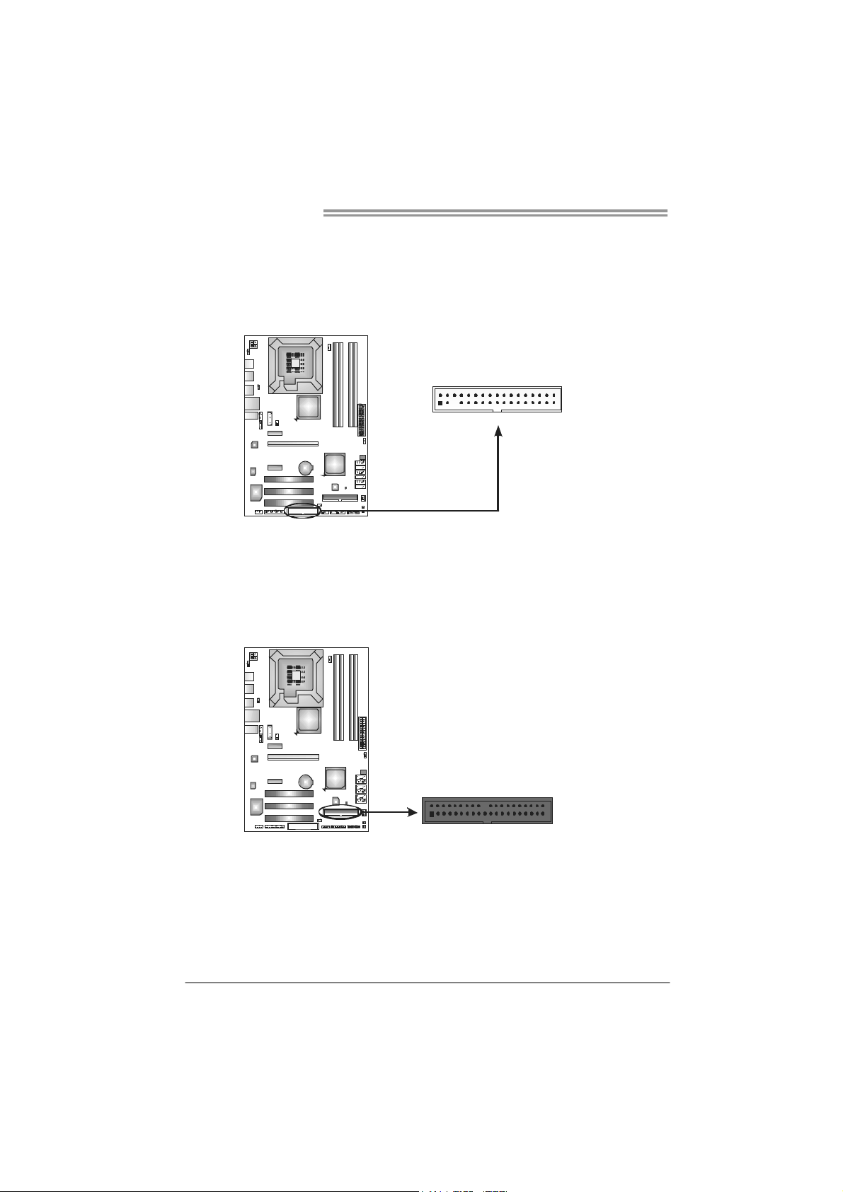
FDD1: Floppy Disk Connector
The motherboard provides a standard floppy disk connector that supports 360K,
720K, 1.2M, 1.44M and 2.88M floppy disk types. This connector supports the
provided floppy drive ribbon cables.
IDE1: Hard Disk Connector
The motherboard has a 32-bit Enhanced PCI IDE Controller that provides PIO
Mode 0~4, Bus Master, and Ultra DMA 33/66/100/133 functionality.
The IDE connector can connect a master and a slave drive, so you can connect
up to two hard disk drives.
2
34
331
10
240
1
39
TP45D2-A7/TP43D2-A7
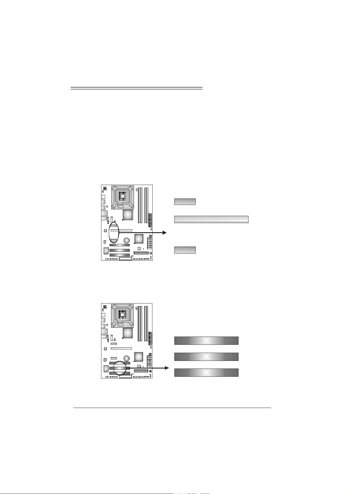
PEX16_1: PCI-Express Gen2 x16 Slot
- PCI-Express 2.0 compliant.
- Maximum theoretical realized bandwidth of 8GB/s simultaneously per
direction, for an aggregate of 16GB/s totally.
- PCI-Express Gen2 supports a raw bit-rate of 5.0Gb/s on the data pins.
- 2X bandwidth over the PCI-Express 1.1 architecture.
PEX1_1/PEX1_2: PCI-Express x1 Slots
- PCI-Express 1.1 compliant.
- Data transfer bandwidth up to 250MB/s per direction; 500MB/s in total.
- PCI-Express supports a raw bit-rate of 2.5Gb/s on the data pins.
- 2X bandwidth over the PCI architecture.
PEX1_1
PEX16_1
PEX1_2
PCI1~PCI3: Peripheral Component Interconnect Slots
This motherboard is equipped with 3 standard PCI slots. PCI stands for
Peripheral Component Interconnect, and it is a bus standard for expansion
cards. This PCI slot is designated as 32 bits.
PCI1
PCI2
PCI3
11
Motherboard Manual
CHAPTER 3: HEADERS & JUMPERS SETUP
3.1 H
OW TO SETUP JUMPERS
The illustration shows how to set up jumpers. When the jumper cap is
placed on pins, the jumper is “close”, if not, that means the jumper is
“open”.
Pin opened Pin closed Pin1-2 closed
3.2 D
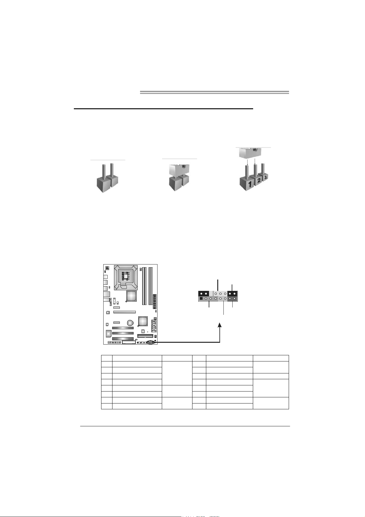
JPANEL1: Front Panel Header
ETAIL SETTINGS
This 16-pin connector includes Power-on, Reset, HDD LED, Power LED, and
speaker connection. It allows user to connect the PC case’s front panel switch
functions.
PWR_LED
9
1
SPK
++
HLED
+
On/Off
-
-
RST
16
8
12
Pin Assignment Function Pin Assignment Function
1 +5V 9 N/A
2 N/A 10 N/A
3 N/ A 11 N/ A N/A
4 Speaker
5 HDD LED (+) 13 Power LED (+)
6 HDD LED (-)
7 Ground 15 Power button
8 Reset control
Speaker
Connector
Hard drive
LED
Reset button
12 Power LED (+)
14 Power LED (-)
16 Ground
N/A
Power LED
Power-on button
TP45D2-A7/TP43D2-A7
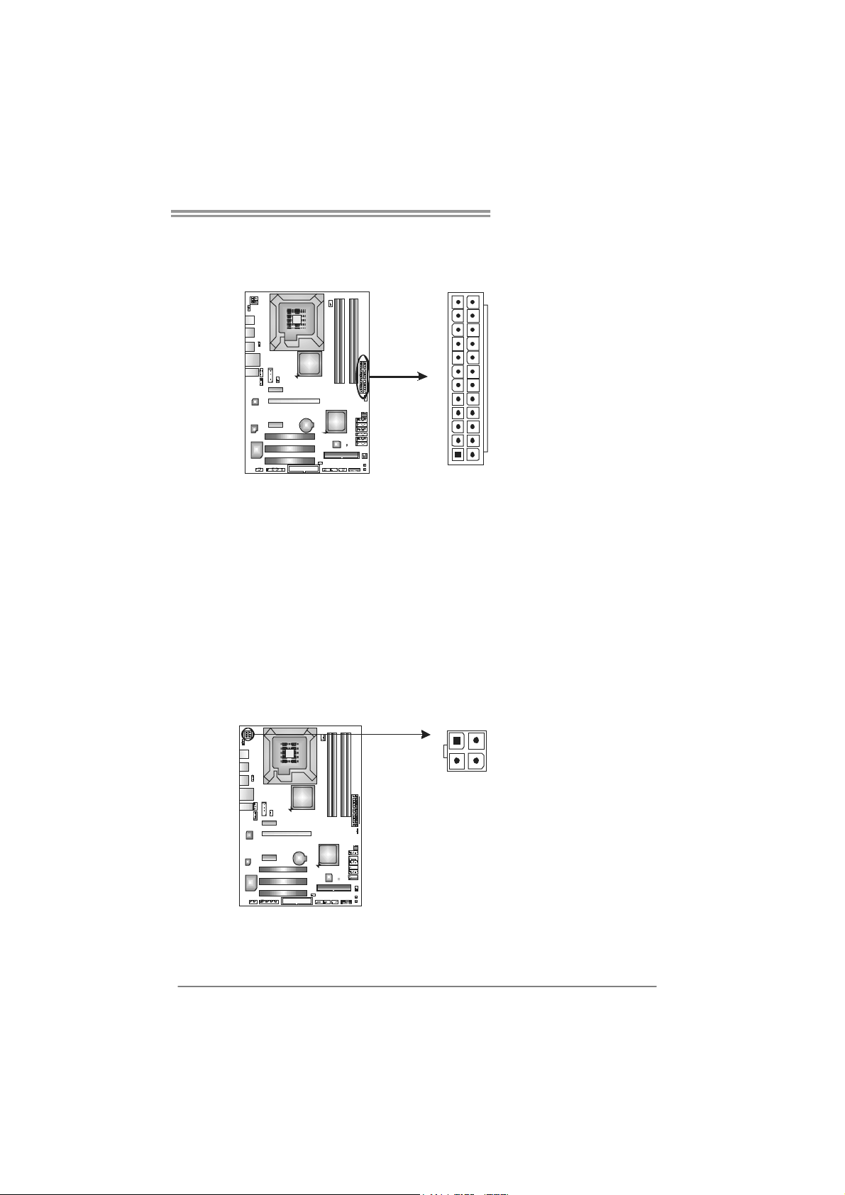
JATXPWR1: AT X Power Source Connector
This connector allows user to connect 24-pin power connector on the ATX
power supply.
12
1
Pin Assignment Pin Assignment
13 +3.3V 1 +3.3V
14 -12V 2 +3.3V
15 Ground 3 Ground
16 PS_ON 4 +5V
17 Ground 5 Ground
18 Ground 6 +5V
19 Ground 7 Ground
20 NC 8 PW_OK
21 +5V 9 Standby Voltage+5V
22 +5V 10 +12V
23 +5V 11 +12V
24 Ground 12 +3.3V
24
13
JATXPWR2: AT X Power Source Connector
By connecting this connector, it will provide +12V to CPU power circuit.
1
4
23
Pin
Assignment
1 +12V
2 +12V
3 Ground
4 Ground
Note:
Before power on the s ystem, please make sure that both JATXPWR1 and JATXPWR2
connectors have been plugged-in.
13
Motherboard Manual
J1: Auxiliary Power for Graphics
This connector is an auxiliary power connection for graphics cards. Exclusive
power for the graphics card provides better graphics performance.
SATA1~SATA6: Serial ATA Connectors
The motherboard has a PCI to SATA Controller with 6 channels SATA interface,
it satisfies the SATA 2.0 spec and with transfer rate of 3.0Gb/s.
4
1
SATA1
SATA2
SATA3
SATA4
SATA5
SATA6
147
Pin
Assignment
1 +12V
2 Ground
3 Ground
4 VCC
Pin
Assignment
1 Ground
2 TX+
3 TX4 Ground
5 RX6 RX+
7 Ground
14
TP45D2-A7/TP43D2-A7
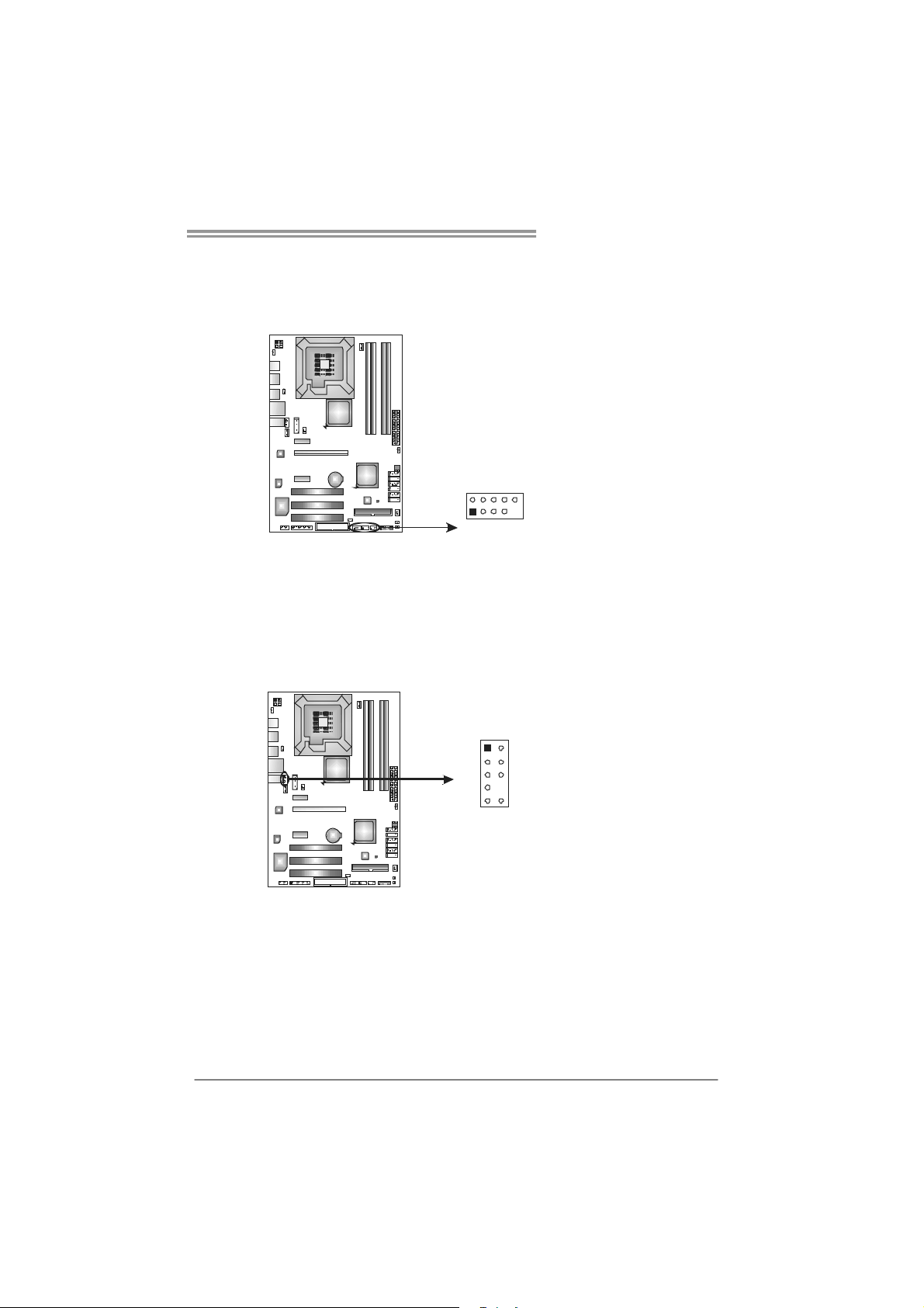
JUSB3/JUSB4/JUSB5: Headers for USB 2.0 Ports at Front Panel
This header allows user to connect additional USB cable on the PC front panel,
and also can be connected with internal USB devices, like USB card reader.
Assignment
Pin
1 +5V (fused)
2 +5V (fused)
3 USB4 USB5 USB+
6 USB+
7 Ground
8 Ground
9 Key
10 NC
JUSB4
JUSB5JUSB3
2
1
10
9
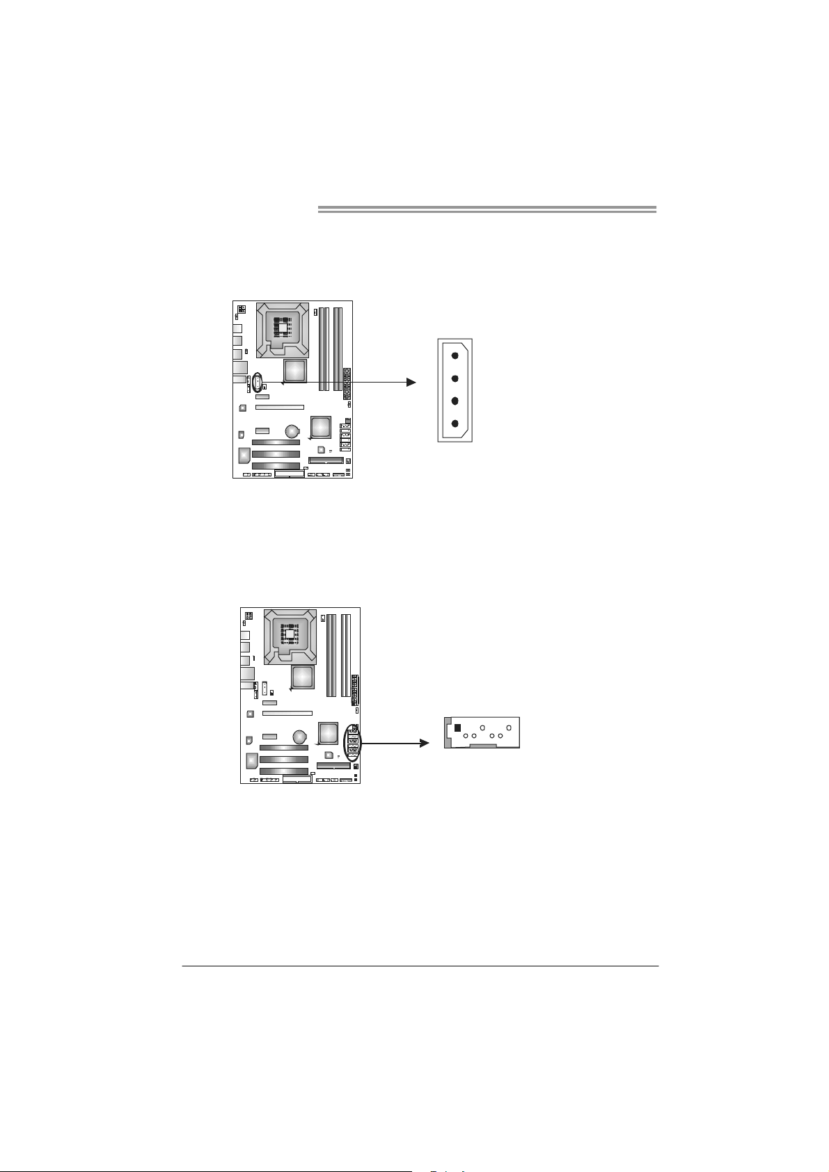
JAUDIOF1: Front Panel Audio Header
This header allows user to connect the front audio output cable with the PC front
panel. This header allows only HD audio front panel connector; AC’97 connector
is not acceptable.
Pin Assignment
1 Mic Left in
12
910
2 Ground
3 Mic Right in
4 GPIO
5 Right line in
6 Jack Sense
7 Front Sense
8 Key
9 Left line in
10 Jack Sense
15
Motherboard Manual
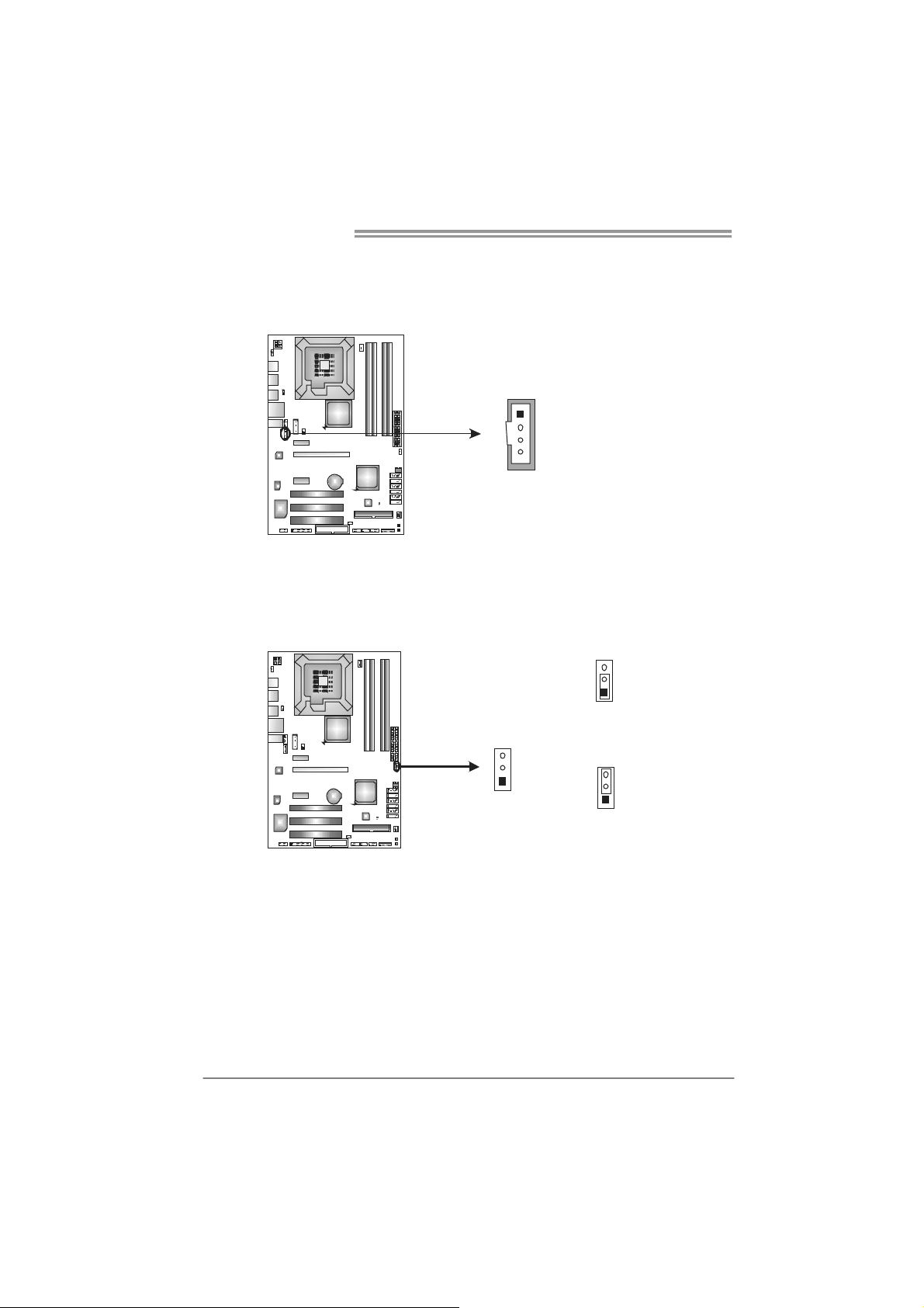
JCDIN1: CD-ROM Audio-in Connector
This connector allows user to connect the audio source from the variaty devices,
like CD-ROM, DVD-ROM, PCI sound card, PCI TV turner card etc..
JCMOS1: Clear CMOS Header
By placing the jumper on pin2-3, it allows user to restore the BIOS safe setting
and the CMOS data, please carefully follow the procedures to avoid damaging
the motherboard.
Assignment
Pin
1
4
1 Left Channel Input
2 Ground
3 Ground
4 Right Channel Input
3
1
Pin 1-2 Close:
Normal Operation (default).
16
3
1
3
1
Pin 2-3 Close:
Clear CMOS data.
※ Clear CMOS Procedures:
1. Remove AC power line.
2. Set the jumper to “Pin 2-3 close”.
3. Wait for five seconds.
4. Set the jumper to “Pin 1-2 close”.
5. Power on the AC.
6. Reset your desired password or clear the CMOS data.

TP45D2-A7/TP43D2-A7
On-Board LED Indicators
There are 2 LED indicators on the motherboard to show system status.
LED_D1
LED_D2
LED_D1 and LED_D2:
These 2 LED indicate system power on diagnostics.
Please refer to the table below for different messages:
LED_D1 LED_D2 Message
ON ON Norma l
ON OFF Memory Error
OFF ON VGA Error
OFF OFF Abnormal: CPU / Chipset error.
On-Board Buttons
There are 2 on-board buttons.
PWRSW1:
This is an on-board Power Switch button.
RSTSW2:
This is an on-board Reset button.
RS TSW 2
PWRSW1
17
 Loading...