

Biostar TA880GB+ Owner's Manual

TA880GB+/TA880GB Setup Manual
FCC Information and Copyright
This equipment has been tested and found to comply with the limits of a Class
B digital device, pursuant to Part 15 of the FCC Rules. These limits are designed
to provide reasonable protection against harmful interference in a residential
installation. This equipment generates, uses, and can radiate radio frequency
energy and, if not installed and used in accordance with the instructions, may
cause harmful interference to radio communications. There is no guarantee
that interference will not occur in a particular installation.
The vendor makes no representations or warranties with respect to the
contents here and specially disclaims any implied warranties of merchantability
or fitness for any purpose. Further the vendor reserves the right to revise this
publication and to make changes to the contents here without obligation to
notify any party beforehand.
Duplication of this publication, in part or in whole, is not allowed without first
obtaining the vendor’s approval in writing.
The content of this user’s manual is subject to be changed without notice and
we will not be responsible for any mistakes found in this user’s manual. All the
brand and product names are trademarks of their respective companies.

Table of Contents
Chapter 1: Introduction ........................................ 1
1.1 Before You Start ................................................................................ 1
1.2 Package Checklist............................................................................. 1
1.3 Motherboard Features...................................................................... 2
1.4 Rear Panel Connectors ..................................................................... 3
1.5 Motherboard Layout......................................................................... 4
Chapter 2: Hardware Installation .......................... 5
2.1 Installing Central Processing Unit (CPU)....................................... 5
2.2 FAN Headers...................................................................................... 7
2.3 Installing System Memory ................................................................ 8
2.4 Connectors and Slots....................................................................... 10
Chapter 3: Headers & Jumpers Setup .................. 13
3.1 How to Setup Jumpers .................................................................... 13
3.2 Detail Settings.................................................................................. 13
Chapter 4: Hybrid CrossFireX Function ................ 19
4.1 Hybrid CrossFireX Requirements.................................................. 19
4.2 Hybrid CrossFireX Installation....................................................... 19
Chapter 5: RAID Functions .................................. 20
5.1 Operating System............................................................................ 20
5.2 Raid Arrays ...................................................................................... 20
5.3 How RAID Works............................................................................. 20
Chapter 6: T-Series BIOS & Software................... 23
6.1 T-Series BIOS..................................................................................... 23
6.2 T-Series Software ............................................................................. 31
Chapter 7: Useful Help ........................................ 41
7.1 Driver Installation Note.................................................................. 41
7.2 Extra Information............................................................................ 42
7.3 AMI BIOS Beep Code....................................................................... 43
7.4 Troubleshooting............................................................................... 44
Appendix: SPEC In Other Languages ................... 46
German.................................................................................................................. 46
French .................................................................................................................... 48
Italian..................................................................................................................... 50
Spanish ................................................................................................................... 52
Portuguese ............................................................................................................ 54
Polish...................................................................................................................... 56
Russian ................................................................................................................... 58
Arabic..................................................................................................................... 60
Japane se ................................................................................................................ 62

CHAPTER 1: INTRODUCTION
TA880GB+/TA880GB
1.1 B
EFORE YOU START
Thank you for choosing our product. Before you start installing the
motherboard, please make sure you follow the instructions below:
Prepare a dry and stable working environment with
sufficient lighting.
Always disconnect the computer from power outlet
before operation.
Before you take the motherboard out from anti-static
bag, ground yourself properly by touching any safely
grounded appliance, or use grounded wrist strap to
remove the static charge.
Avoid touching the components on motherboard or the
rear side of the board unless necessary. Hold the board
on the edge, do not try to bend or flex the board.
Do not leave any unfastened small parts inside the
case after installation. Loose parts will cause short
circuits which may damage the equipment.
Keep the computer from dangerous area, such as heat
source, humid air and water.
The operating temperatures of the computer should be
0 to 45 degrees Celsius.
1.2 PACKAGE CHECKLIST
IDE Cable X 1 (optional)
Serial ATA Cable X 3
Serial ATA Power Cable X 1
Rear I/O Panel for ATX Case X 1
User’s Manual X 1
Fully Setup Driver CD X 1
FDD Cable X 1 (optional)
USB 2.0 Cable X1 (optional)
S/PDIF out Cable X 1 (optional)
Note: The package contents may be different due to area or your motherboard version.
1
Motherboard Manual
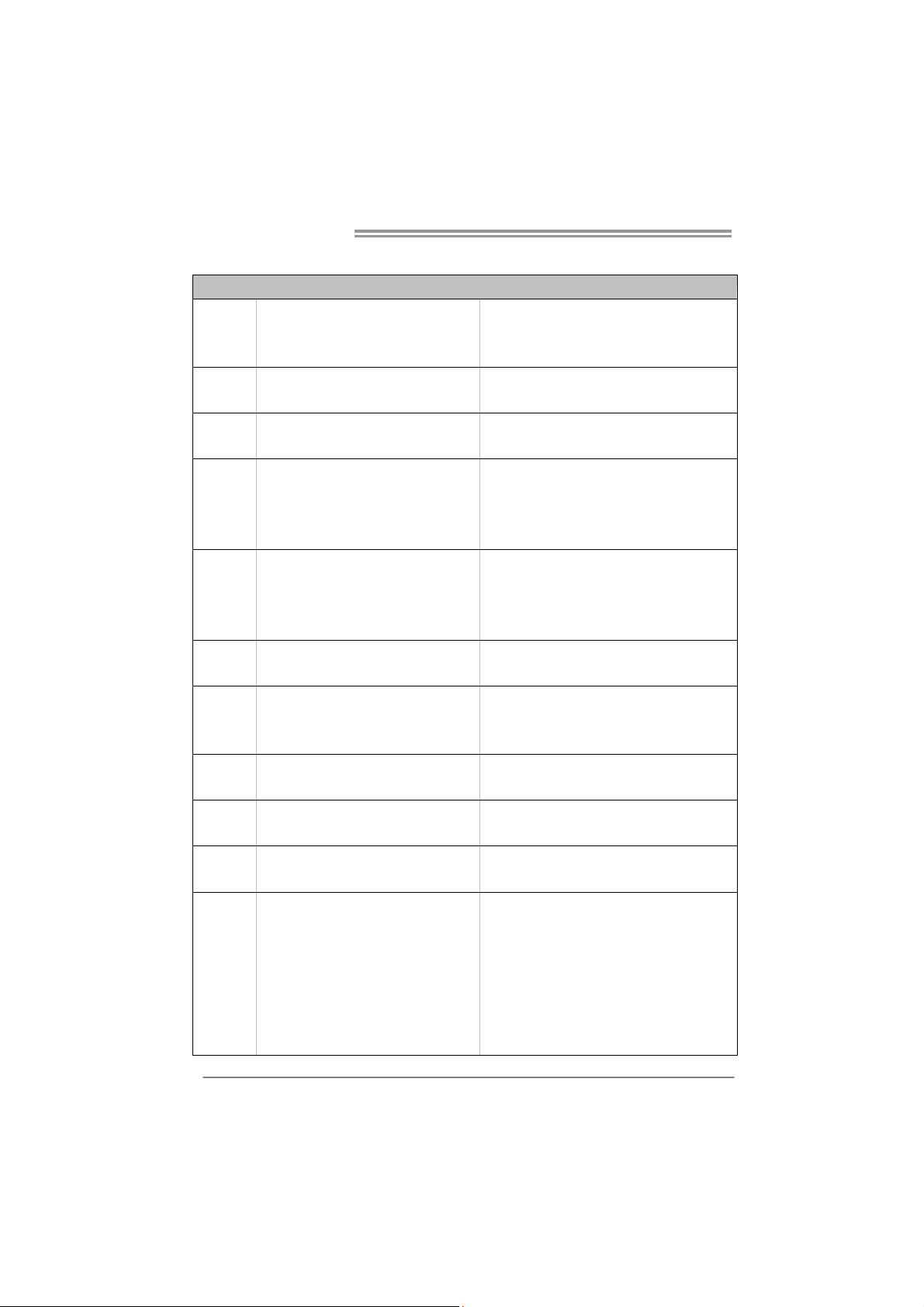
1.3 MOTHERBOARD FEATURES
Socket AM3
CPU
FSB
Chipset
Super I/O
Main
Memory
Graphics
SATA 2
LAN
Sound
Slots
On Board
Connectors
AMD Sempron / Phenom II / Athlon II
processors
Support HyperTransport 3.0
Supports up to 5.2 GT/s Bandwidth
AMD 880G
AMD SB710
ITE 8721
Prov ides the most common ly used leg acy
Super I/O functionality.
Low Pin Count Interface
DDR3 DIMM Slots x 4
Max Memory Capacity 16GB
Each DIMM supports 512MB/
1GB/2GB/4GB DDR3
AMD 880G (Radeon HD4250)
Integrated Serial ATA Controller
Realtek RTL8111E
ALC892
PCI Slot x2 Supports PCI expansion cards
PCI Express Gen2 x16 S lot x1 Supports PCI-E Gen2 x16 expansion card
SATA Connect or x6 Each connector s upports 1 SATA device
Front Panel Connector x1 Supports front panel facilities
Front Audio Connector x1 Supports front panel audio function
S/PD IF out Connector x1 Supports digital audio out function
CPU Fan Header x1 CPU Fan power supply (with Smart Fan function)
System Fan Header x2 System Fan Power supply
CMOS clear Header x1 Restore CMOS data to factory default
SPEC
AMD 64 Architecture enables 32 and 64 b it
computing
Supports Hyper Transport 3.0
En viro nment Co ntrol in itiat ives ,
H/W Mon itor
Fan Sp eed Contro ller
ITE's "S mart Guard ian " funct ion
Dual Channel Mode DDR3 memo ry module
Supports DDR3 800 / 1066 / 1333
Supports DDR3 1600 (OC)
Max S hared V ideo Memory is 51 2 MB
DVI/HDMI/UVD/HDCP support
Data transfer rates up to 3 Gb/s.
SATA Vers ion 2.0 spe c if ic at ion co mpl iant.
RAID 0,1,10 support
10 / 100 Mb/s / 1Gb/s auto negotiation
Half / Full duplex capability
5.1channels audio out
Supports HD Audio
2
Back Panel
I/O
Board Size
OS Support
TA880GB+/TA880GB
SPEC
USB Connector x3 Each connector s upports 2 front panel USB port s
Printer Port Connector x1 Each connector supports 1 Printer port
Serial Port Connector x1 Connects to RS-232 Port
Consumer IR Connector x1 Supports infrared function
Power Connector (24pin) x1 Connects to Power supply
Power Connector (4pin) x1 Connects to Power supp ly
PS/2 Keyboard / Mouse x1
HDMI Port x1
VGA Port x1
DVI-D Port x1
LAN Port x1
USB Port x4
Audio Jack x3
233 mm (W) x 244 mm (L) uATX
Windows XP / Vista / 7
Connects to PS/2 Keyboard / Mouse
Connects to HDMI cable
Connect to D-SUB monitor
Connect to DVI monitor
Connect to RJ-45 ethernet cable
Connect to USB dev ices
Provide Audio-In/Out and microphone connection
Biostar reserves the right to add or remove support
for any OS With or without notice.
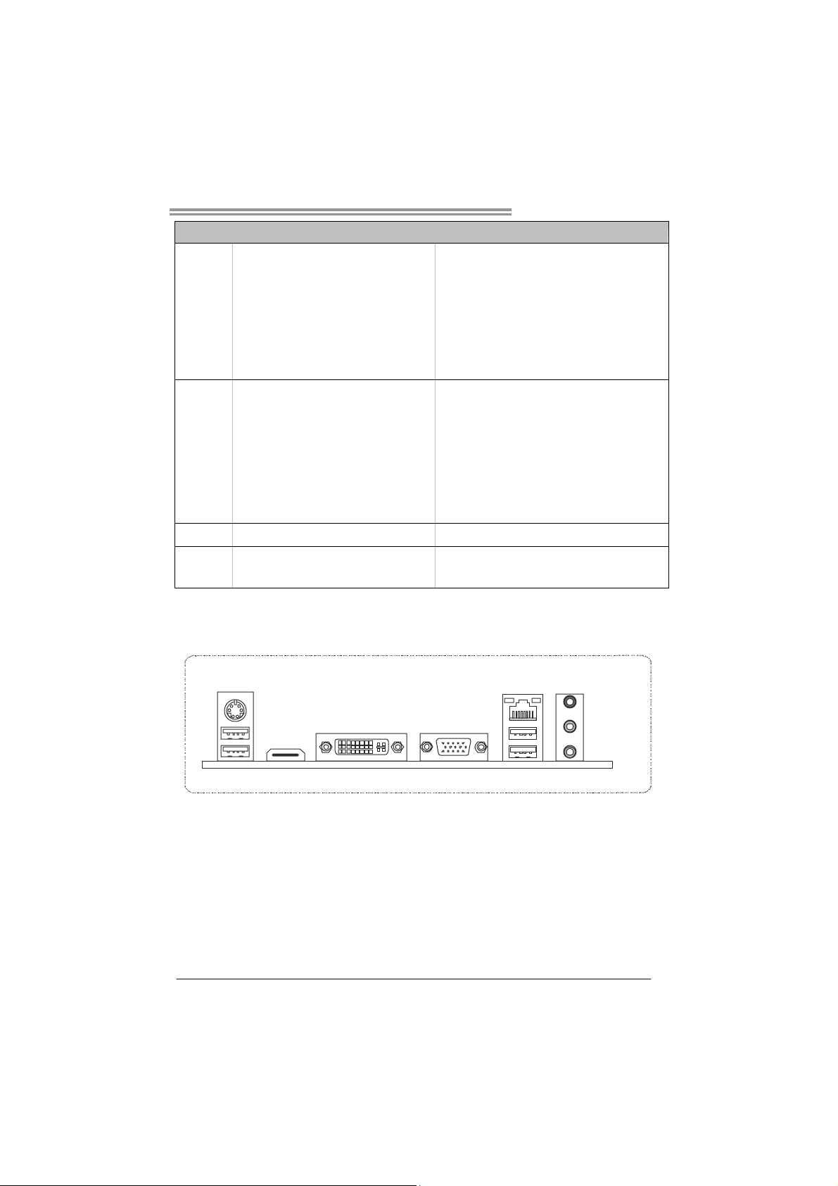
1.4 REAR PANEL CONNECTORS
PS/2
Keyboa rd / Mouse
USBX2
HDMI
VGADVI-D
NOTE: The HDMI and DVI-D ports both can provide digital video signals out-put function, but
these two interfaces cannot work at the same time. The chipset uses the same channel
to control HDMI and DVI-D, so these ports cannot transmit video signal to different display
panels simultaneously.
LAN
USBX2
Line In/
Surrou nd
Line Out
Mic In 1/
Bass/ Center
3
Motherboard Manual
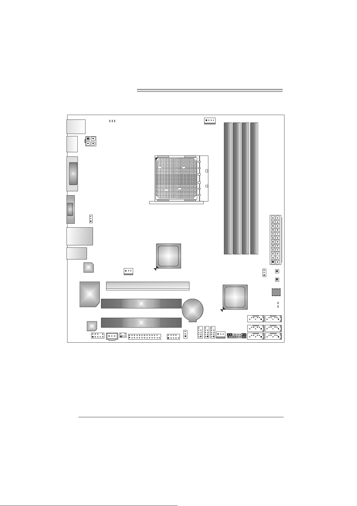
1.5 MOTHERBOARD LAYOUT
PH3_D 3
PH2_D 2
USB_
KBMS1
HD MI1
DVI1
VGA1
RJ4 5USB1
ATXPWR 2
PH1_D 1
JUSBV 1
CPU_FAN1
Socket AM3
DDR 3_A 1
DB1DR3_
DB2DR3_
DA2DR3_
AT XP W R 1
AUD IO1
4
LAN
Super
I/O
Codec
F_AU DI O1
Note: represents the 1■
JSP DIFOUT 1
CIR1
SYS_FAN1
PEX16_1
PCI1
PCI2
AMD
880G
J_COM1J_PRINT1
st
JUSB V2
pin.
BAT1
F_USB1
F_USB2
F_USB3
SB710
SYS_FAN 2
AMD
PANE L1
JCMOS 1
SATA3
SATA2
SATA 1
SW_PWR1
SW_RST1
BIOS
LED_D2
LED_D1
SATA6
SATA5
SATA4
TA880GB+/TA880GB
CHAPTER 2: HARDWARE INSTALLATION
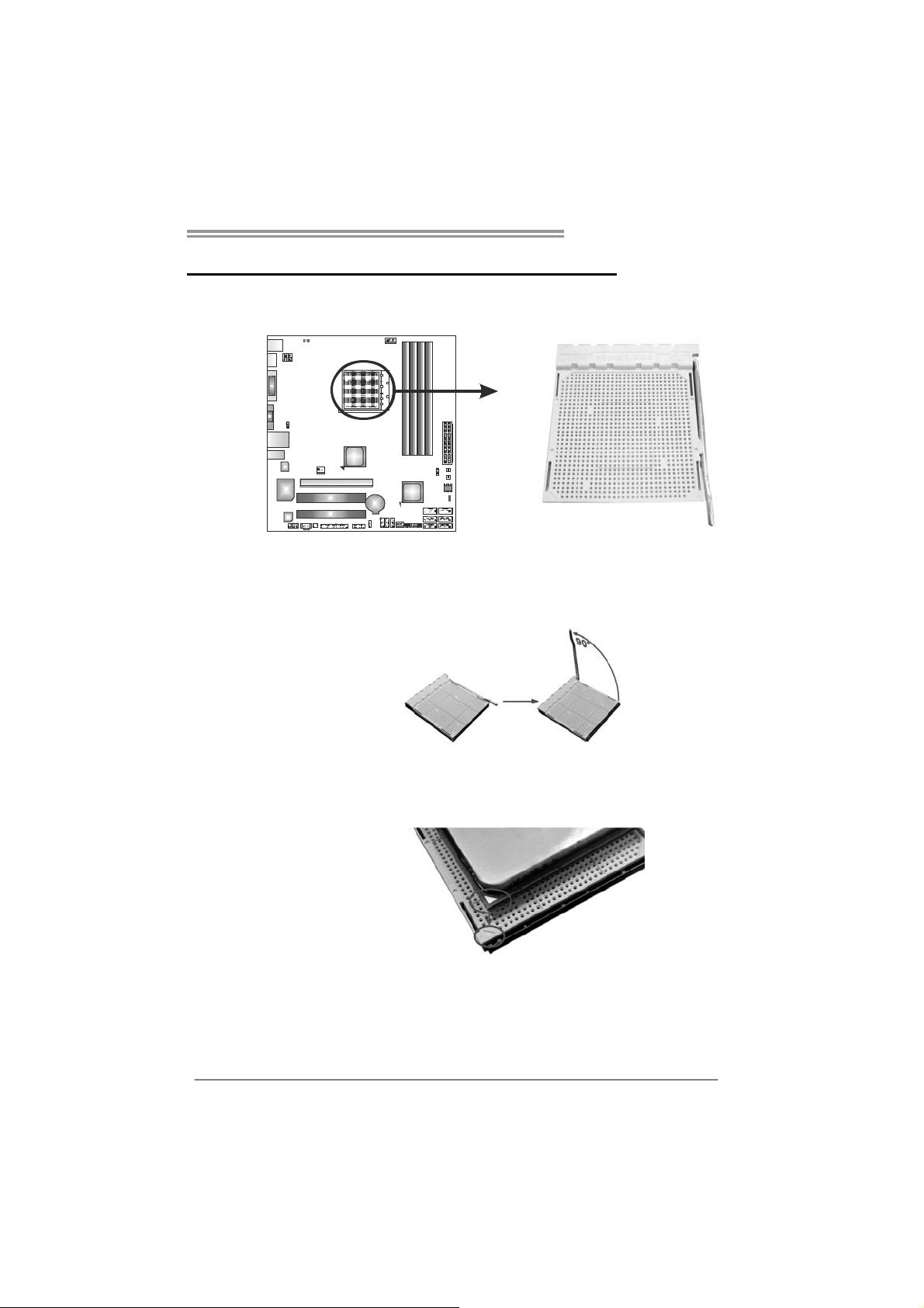
2.1 I
NSTALLING CENTRAL PROCESSING UNIT (CPU)
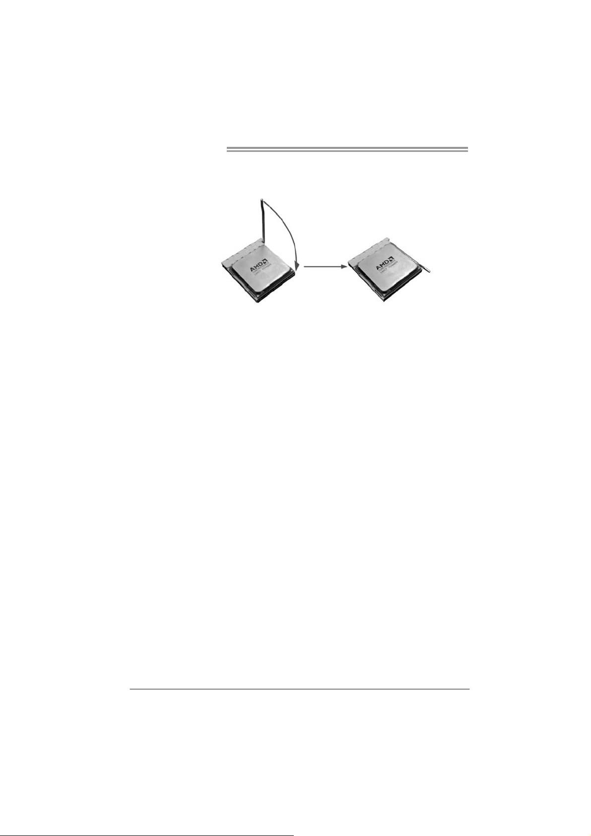
Step 1: Pull the lever toward direction A from the socket and then raise the
lever up to a 90-degree angle.
Step 2: Look for the white triangle on socket, and the gold triangle on
CPU should point towards this white triangle. The CPU will fit only
in the correct orientation.
5
Motherboard Manual
Step 3: Hold the CPU down firmly, and then close the lever toward direct
B to complete the installation.
Step 4: Put the CPU Fan on the CPU and buckle it. Connect the CPU
FAN power cable to the CPU_FAN1. This completes the
installation.
6
TA880GB+/TA880GB
1
4
2.2 FAN HEADERS
These fan headers support cooling-fans built in the computer. The fan
cable and connector may be different according to the fan manufact urer.
Connect the fan cable to the connector while matching the black wire to
pin#1.
CPU_FAN1: CPU Fan Header
Pin
1 Ground
2 +12V
3
4 Smart Fan
SYS_FAN1: NorthBridge Fan Header
SYS_FAN2: System Fan Header
Pin Assignment
1 Ground
2 +12V
3
SYS_FAN1
13
Assignment
FAN RPM r at e
sense
Control (By Fan)
FAN RPM
rate sense
SYS_FAN2
Note:
CPU_FAN1, SYS_FAN1/2 support 4-pin and 3-pin head connectors. When connecting
with wires onto connectors, please note that the red wire is the positive and should be
connected to pin#2, and the black wire is Ground and should be connected to GND.
7
Motherboard Manual
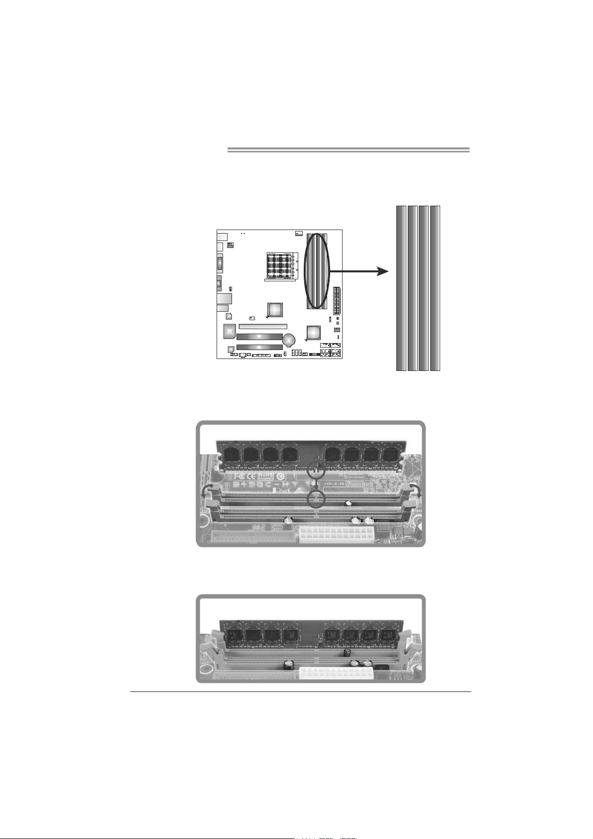
2.3 INSTALLING SYSTEM MEMORY
A. DDR3 Modules
DDR 3_A1
1. Unlock a DIMM slot by pressing the retaining clips outward. Align a
DIMM on the slot such that the notch on the DIMM matches the
break on the Slot.
DB1DR 3_
DA2DR 3_
DB2DR 3_
2. Insert the DIMM vertically and firmly into the slot until the retaining
chip snap back in place and the DIMM is properly seated.
8
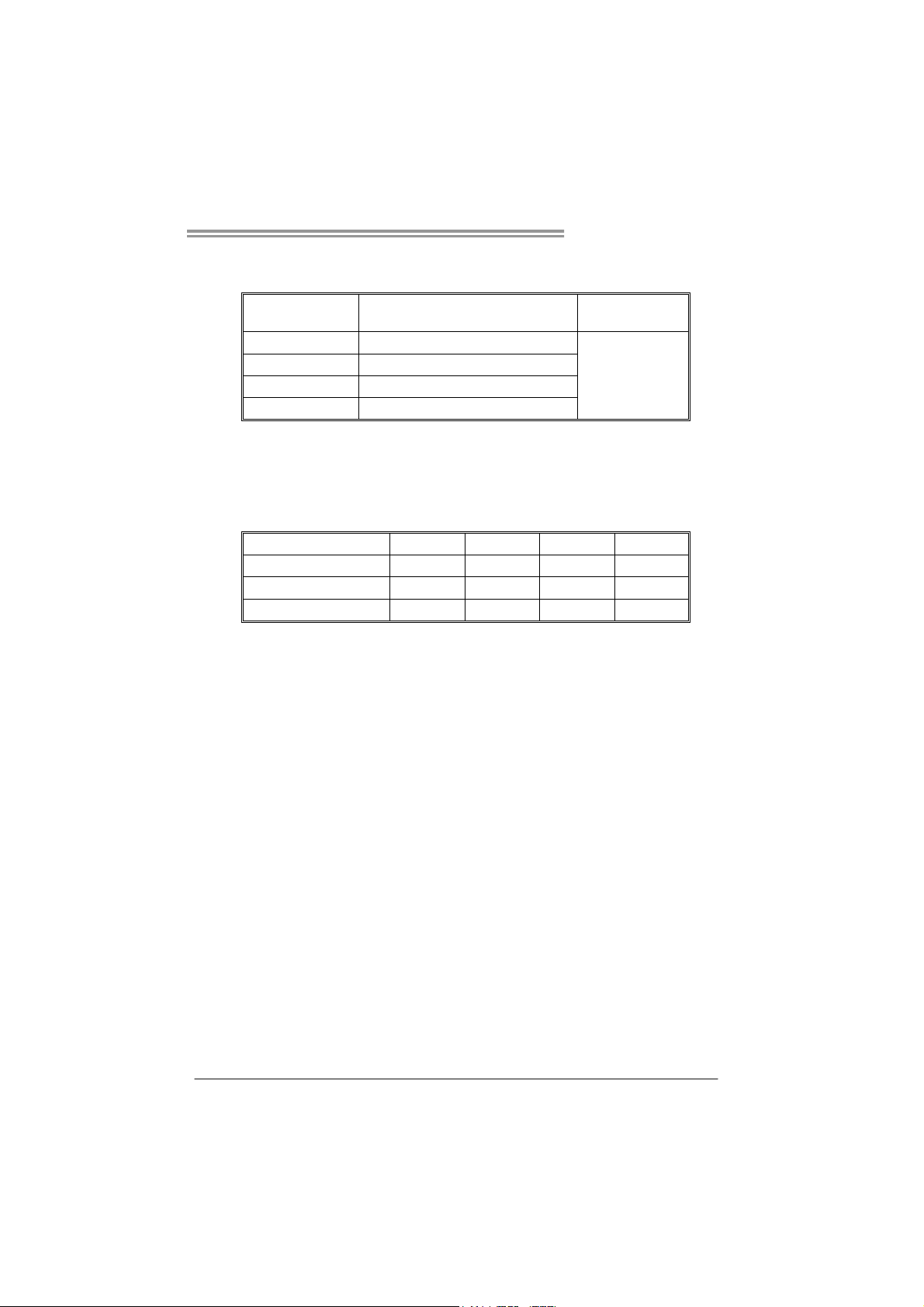
B. Memory Capacity
TA880GB+/TA880GB
DIMM Socket
Location
DDR3_A1 512MB/1GB/2GB/4GB
DDR3_B1 512MB/1GB/2GB/4GB
DDR3_A2 512MB/1GB/2GB/4GB
DDR3_B2 512MB/1GB/2GB/4GB
DDR3 Module
C. Dual Channel Memory installation
Please refer to the following requirements to activate Dual Channel function:
Install memory module of the same density in pairs, shown in the table.
Dual Channel Status
Enabled O O X X
Enabled X X O O
Enabled O O O O
(O means memory installed, X means memory not installed.)
The DRAM bus width of the memory module must be the same (x8 or
x16)
DDR3_A1
Total M emory
Size
Max is 16GB.
DDR3_B1 DDR3_A2 DDR3_B2
9
Motherboard Manual
2.4 CONNECTORS AND SLOTS
SATA1~SATA6: Serial ATA Connectors
The motherboard has a PCI to SATA Controller with 6 channels SATA interface,
it satisfies the SATA 2.0 spec and with transfer rate of 3.0Gb/s.
ATXP W R2: AT X P ower Source Connector
Connecting this connector will provide +12V to CPU power circuit.
S ATA 3 SATA 6
S ATA 2 SATA 5
S ATA 1 SATA 4
147
41
Pin
1 Ground
2 TX+
3 TX4 Ground
5 RX6 RX+
7 Ground
Assignment
10
23
Pin Assignment
1 +12V
2 +12V
3 Ground
4 Ground
TA880GB+/TA880GB
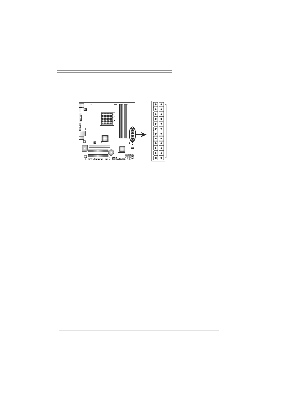
ATXP W R1: AT X P ower Source Connector
This connector allows user to connect 24-pin power connector on the AT X
power supply.
12
1
Pin Assignment Pin Assignment
13 +3.3V 1 +3.3V
14 -12V 2 +3.3V
15 Ground 3 Ground
16 PS_ON 4 +5V
17 Ground 5 Ground
18 Ground 6 +5V
19 Ground 7 Ground
20 NC 8 PW_OK
21 +5V 9 Standby Voltage+5V
22 +5V 10 +12V
23 +5V 11 +12V
24 Ground 12 +3.3V
24
13
Note:
Before power on the system, please make sure that both ATXPWR1 and ATXPWR2
connectors have been plugged-in.
11
Motherboard Manual
PEX16_1: PCI-Express Gen2 x16 Slot
- PCI-Express 2.0 compliant.
- Maximum theoretical realized bandwidth of 8GB/s simultaneously per
direction, for an aggregate of 16GB/s totally.
- PCI-Express Gen2 supports a raw bit-rate of 5.0Gb/s on the data pins.
- 2X bandwidth over the PCI-Express 1.1 architecture.
PCI1/PCI2: Peripheral Component Interconnect Slots
This motherboard is equipped with 2 standard PCI slots. PCI stands for
Peripheral Component Interconnect, and it is a bus standard for expansion
cards. This PCI slot is designated as 32 bits.
PEX16_1
12
PCI1
PCI2
TA880GB+/TA880GB
CHAPTER 3: HEADERS & JUMPERS SETUP
3.1 H
OW TO SETUP JUMPERS
The illustration shows how to set up jumpers. When the jumper cap is
placed on pins, the jumper is “close”, if not, that means the jumper is
“open”.
Pin opened Pin closed Pin1-2 closed
3.2 DETAIL SETTINGS
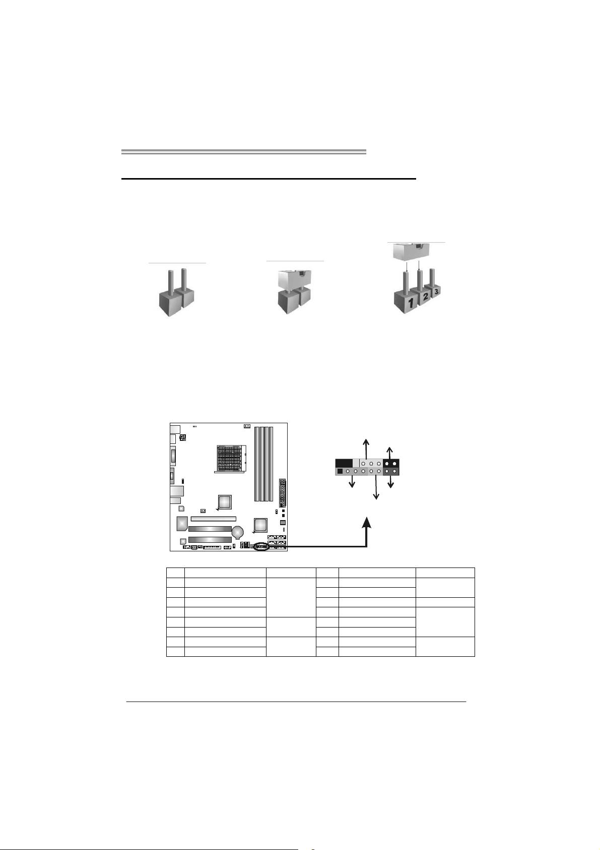
PANEL1: Front Panel Header
This 16-pin connector includes Power-on, Reset, HDD LED, Power LED, and
speaker connection. It allows user to connect the PC case’s front panel switch
functions.
E
D
W
R
P
_
L
O
n
f
O
f
/
-
+
916
1
+
8
-
+
R
S
K
P
S
T
D
E
L
H
Pin Assignment Function Pin Assignment Function
1 +5V 9 N/A
2 N/A 10 N/A
3 N/A 11 N/ A N/A
4 Speaker
5 HDD LED (+) 13 Power LED (+)
6 HDD LED (-)
7 Ground 15 Power button
8 Reset control
Speaker
Connector
Hard drive
LED
Reset button
12 Power LED (+)
14 Power LED (-)
16 Ground
N/ A
Power L ED
Power-on button
13
Motherboard Manual
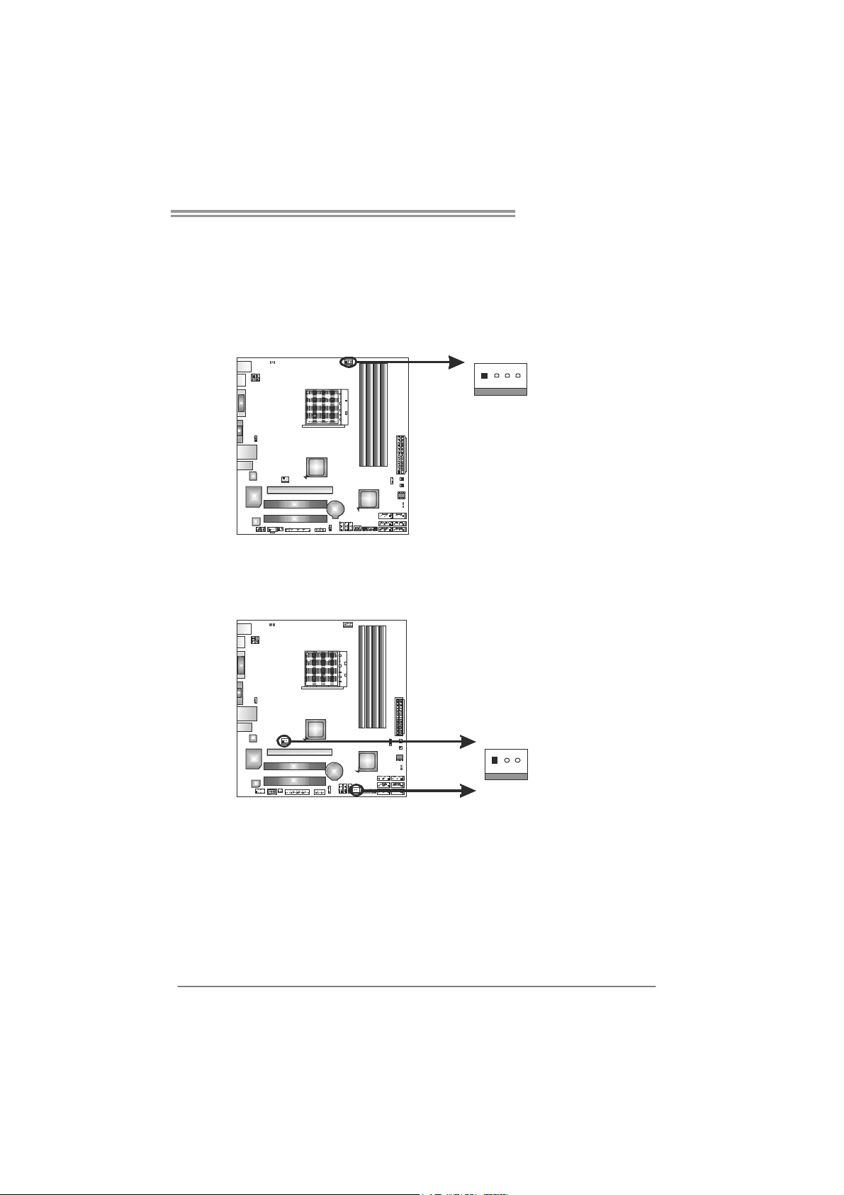
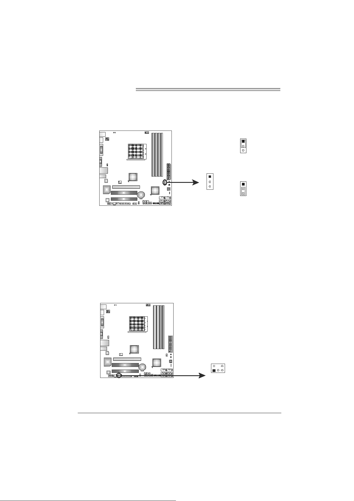
JCMOS1: Clear CMOS Header
Placing the jumper on pin2-3 allows user to restore the BIOS safe setting and
the CMOS data. Please carefully follow the procedures to avoid damaging the
motherboard.
※ Clear CMOS Procedures:
1. Remove AC power line.
2. Set the jumper to “Pin 2-3 close”.
3. Wait for five seconds.
4. Set the jumper to “Pin 1-2 close”.
5. Power on the AC.
6. Reset your desired password or clear the CMOS data.
1
3
Pin 1-2 Close:
Normal Operation
(default).
1
3
Pin 2-3 Close:
Clear CMOS data.
1
3
CIR1: Consumer IR Connector
This header is for infrared remote control and communication.
14
125
Pin Assignment
1 IrDA serial input
2 Ground
3 Ground
4 Key
5 IrDA serial output
6 IR Po wer
6
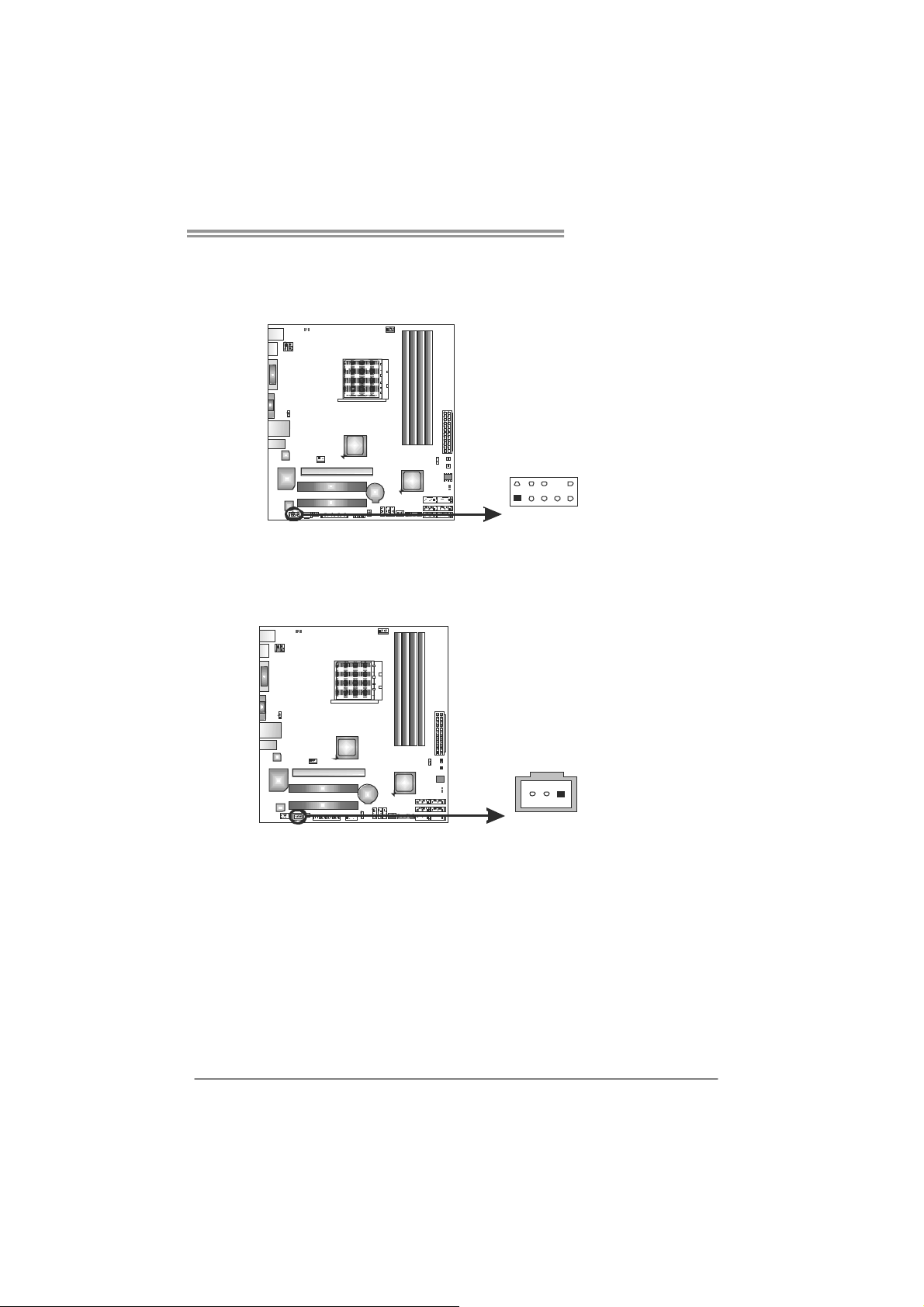
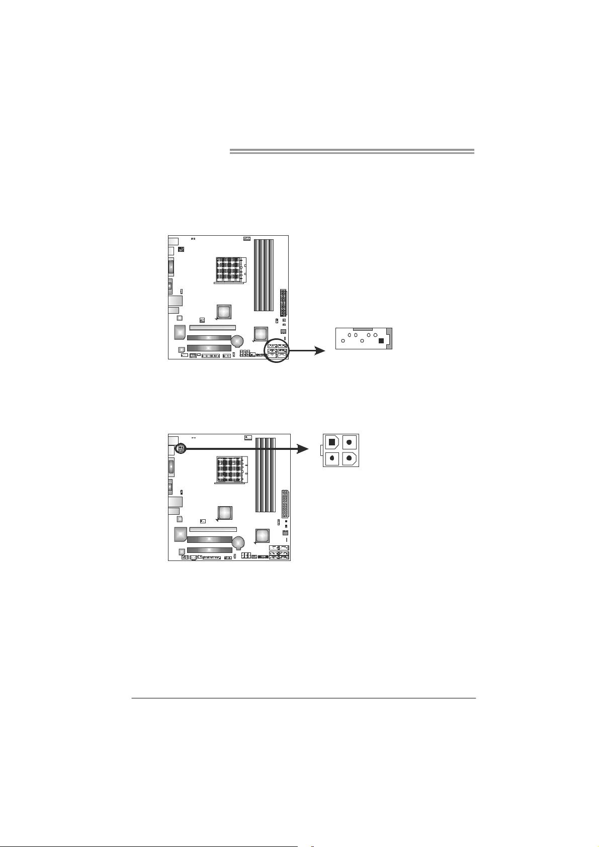
F_AUDIO1: Front Panel Audio Header
This header allows user to connect the front audio output cable with the PC front
panel. This header allows only HD audio front panel connector; AC’97 connector
is not acceptable.
JSPDIFOUT1: Digital Audio-out Connector
This connector allows user to connect the PCI bracket SPDIF output header.
TA880GB+/TA880GB
Pin Assignment
1 Mic Left in
2 Ground
3 Mic Right in
4 GPIO
5 Right line in
6 Jack Sense
7 Front Sense
8 Key
2
1
9 Left line in
10
10 Jack Sense
9
Pin
1 +5V
2 SPDIF_OUT
3 Ground
Assignment
13
15
Motherboard Manual
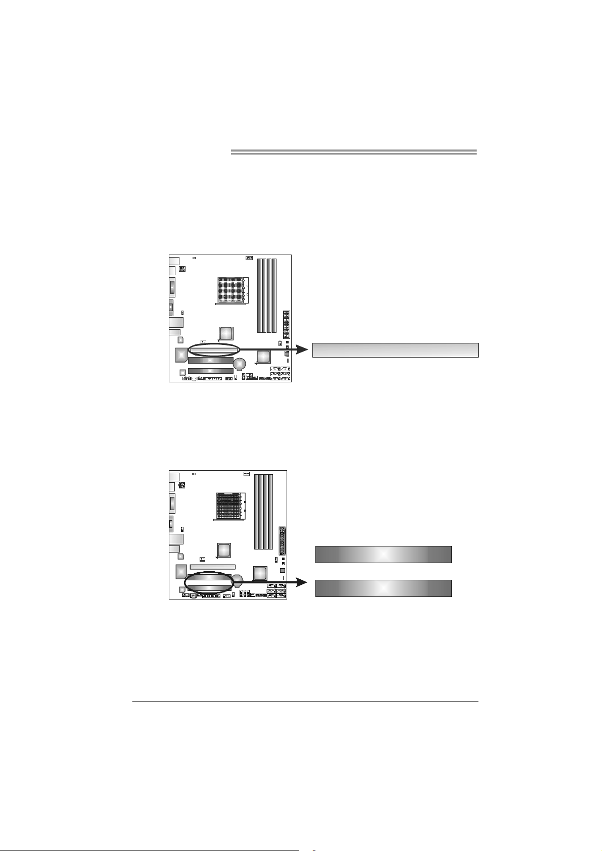
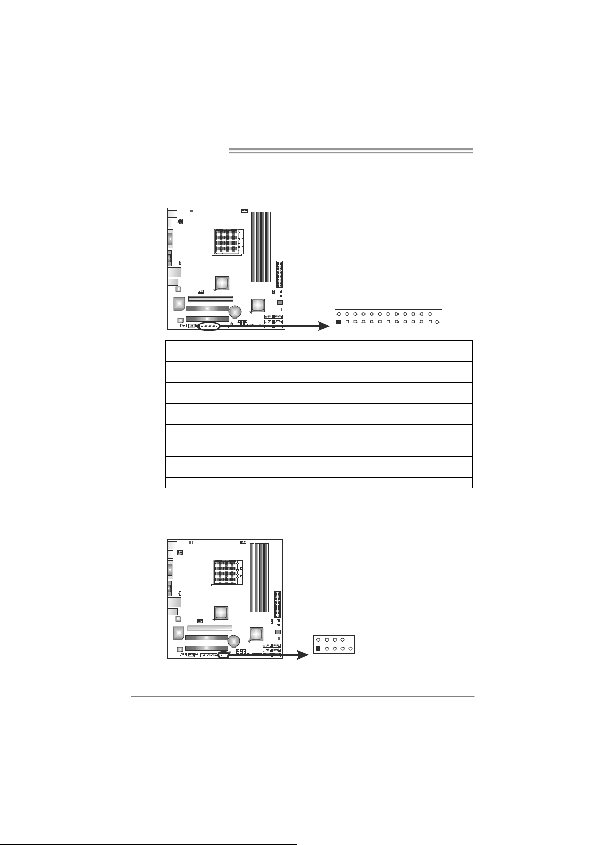
J_PRINT1: Printer Port Connector
This header allows you to connector printer on the PC.
Pin Assignment Pin Assignment
1 -Strobe 14 Ground
2 -ALF 15 Data 6
3 Data 0 16 Ground
4 -Error 17 Data 7
5 Data 1 18 Ground
6 -Init 19 -ACK
7 Data 2 20 Ground
8 -Scltin 21 Busy
9 Data 3 22 Ground
10 Ground 23 PE
11 Data 4 24 Ground
12 Ground 25 SCLT
13 Data 5 26 Key
J_COM1: Serial port Connector
The motherboard has a Serial Port Connector for connecting RS-232 Port.
2
1
Pin Assignment
1 Carrier detect
2 Received data
3 Transmitted data
4 Data terminal ready
5 Signal ground
6 Data set ready
7 Request to send
2
1
10
9
8 Clear to send
9 Ring indicator
10 NC
26
25
16
TA880GB+/TA880GB
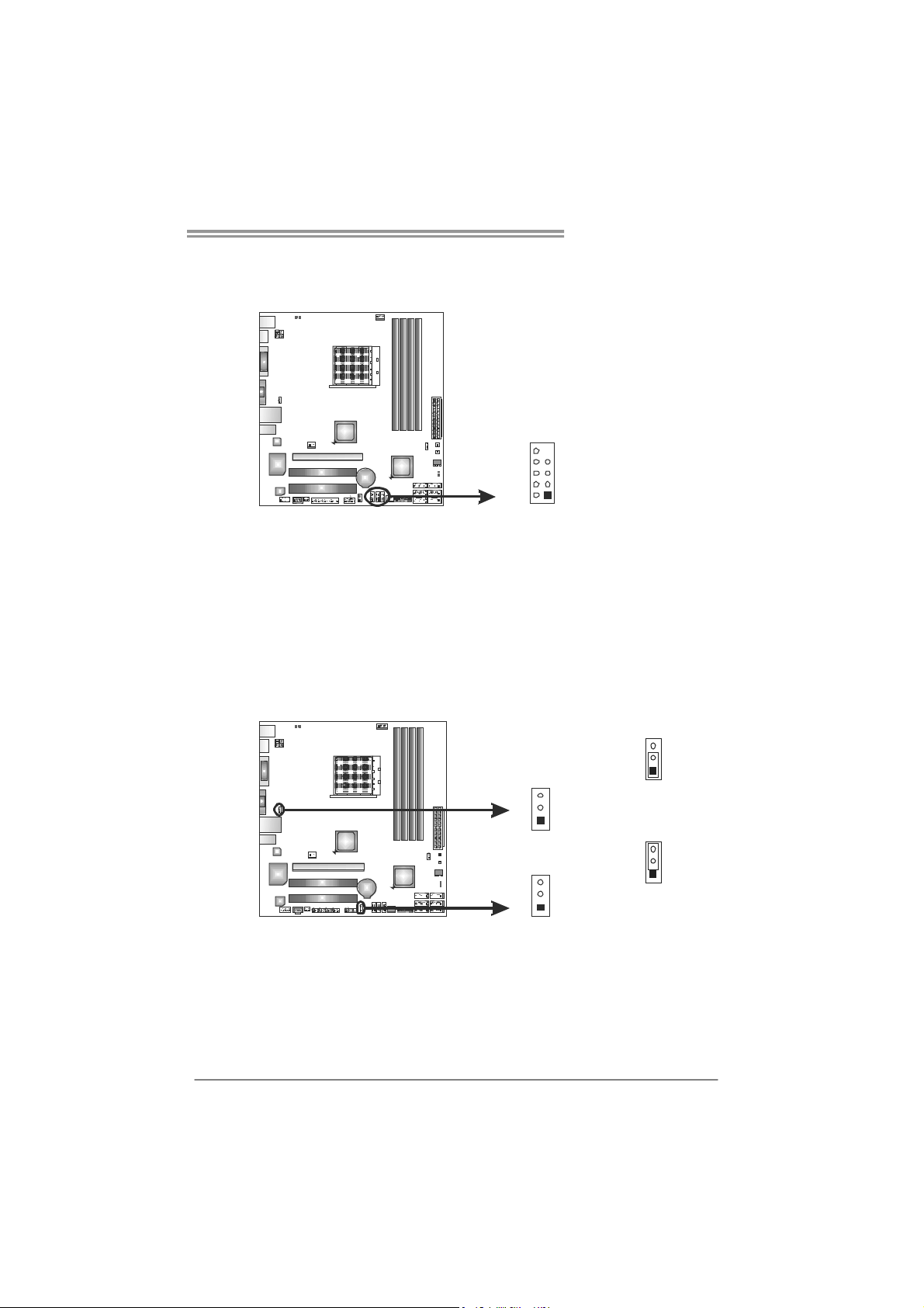
F_USB1~F_USB3: Headers for USB 2.0 Ports at Front Panel
These headers allow user to connect additional USB cable on the PC front panel,
and also can be connected with internal USB devices, like USB card reader.
F_USB 1 F_
F_
USB3
USB2
910
12
JUSBV1/JUSBV2: Power Source Headers for USB Ports
Pin 1-2 Close:
JUSBV1: +5V for USB ports at USB_KBMS1/RJ45USB1.
JUSBV2: +5V for USB ports at F_USB1/F_USB2/F_USB3.
Pin 2-3 Close:
JUSBV1: +5V STB for USB ports at USB_KBMS 1/RJ45USB1.
JUSBV2: +5V STB for USB ports at F_USB1/F_USB2/F_USB3.
Pin
Assignment
1 +5V (fused)
2 +5V (fused)
3 USB4 USB5 USB+
6 USB+
7 Ground
8 Ground
9 Key
10 NC
JUSBV1
3
1
JUSBV2
3
1
3
1
Pin 1-2 close
Pin 2-3 close
3
1
17
Motherboard Manual
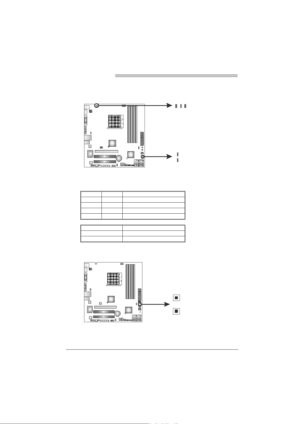
On-Board LED Indicators
There are 5 LED indicators showing system status.
LED_D1 & LED_D2: Debug Indicators
PH1_D1 ~ PH3_D3 Power Status Indicators
Please refer to the tables below for specific messages:
LED_D1 LED_D2 Message
ON ON Norma l
ON OFF Memory Error
OFF ON VGA Error
OFF OFF Abnormal: CPU / Chipset error.
PH1_D1 ~ PH3_D3 Phase Indicator
ON Phase Active
OFF Phase Disable
On-Board Buttons
There are 2 on-board buttons.
PH1_D1
PH2_D2
LED_D2
LED_D1
PH3_D3
18
SW_PWR1
SW_RST 1
SW_RST1: Reset button.
SW_PWR1: Power Switch button.
 Loading...