

Page 1

G31-M7 Setup Manual
FCC Information and Copyright
This equipment has been tested and found to comply with the limits of a Class
B digital device, pursuant to Part 15 of the FCC Rules. These limits are designed
to provide reasonable protec tion ag ainst harmful interfe rence in a residential
installation. T his equipment generates, uses, and can radiate radio frequency
energy and, if not ins talled and used in accordance with the instructions , may
cause harmful interference to radio communications. There is no guarantee
that i nterference wil l not occur in a pa rticula r ins ta lla tio n .
The ve ndor makes no re p resenta tions or warran ties wi th respec t to th e
contents here and specially disclaims any implied warranties of merchantability
o r fi tnes s fo r a ny p u rp os e . Fu rthe r t he ve nd o r res e rves t he ri ght to r ev is e t his
publication and to make changes to the c ontents here without obligation to
notify any party beforehand.
D uplic a tion of this publicatio n , in pa rt o r in wh ol e, is no t allowed wit ho ut first
obtaining the vendor’s approval in writing.
The content of this user’s manual is subject to be c hanged without notice and
we will not be responsible for any mistakes found in this user’s manual. A ll the
brand and produc t names are trademarks of their respective companies.
Page 2

Table of Contents
Chapter 1: Introduction.....................................................1
1.1 Be fo re You Start................................................................... 1
1.2 Package Checklist................................................................ 1
1.3 Motherboard Features.......................................................... 2
1.4 Re ar P anel Connectors.......................................................... 3
1.5 Motherboard Layout ............................................................ 4
Chapter 2: Hardware Installation........................................5
2.1 Installing Central Processing Unit (CPU)................................ 5
2.2 FAN Headers........................................................................ 7
2.3 Installing System Memory...................................................... 8
2.4 Connectors and Slots ............................................................10
Chapter 3: Headers & Jumpers Setup................................. 12
3.1 How to Setup J umpers..........................................................12
3.2 Detail Se ttings.....................................................................12
Chapter 4: Useful Help.....................................................18
4.1 Drive r Installation Note .......................................................18
4.2 AMI BIOS Beep Code............................................................19
4.3 Extra Information................................................................20
4.4 Tro ubleshooting...................................................................22
Appendencies: SPEC In Other Language............................. 24
German................................................................................................24
France..................................................................................................26
Italian..................................................................................................28
Spanish ................................................................................................30
Portuguese...........................................................................................32
Polish...................................................................................................34
Russian................................................................................................36
Arabic..................................................................................................38
Japanese ..............................................................................................40
Page 3

CHAPTER 1: INTRODUCTION
1.1 BEFORE YOU START
Tha nk you for choosing our product. Before you start ins talling the
mo therboa rd, plea se make sure you fo llo w the ins tructio ns be lo w:
Prepare a dry and stable working environment with
s uf ficie nt ligh ting .
Always disconnect the computer from power outlet
be fo re ope ration .
Befo re yo u take the mo the rbo a rd ou t f rom a n ti -s ta ti c
bag, ground yourself properly by touching any safely
grounded applian ce, o r use gro unded wrist strap to
remove the static charge.
Avo id tou ch ing the com pone nts on mo the rboa rd or the
rea r side of the boa rd un les s necessa ry. Ho ld the boa rd
on the edge , do not try to be nd or flex the boa rd.
Do no t lea ve any unfas tened sma ll pa rts inside the
case after installation. Loose parts will cause short
circuits which may damage the equ ipment.
Keep the computer from dangerous area, such as heat
sou rce , humid a ir and water.
1.2 PACKAGE CHECKLIST
HDD Cable X 1
Se ria l ATA Cab le X 1
Use r’s Ma nual X 1
Fully Setup Driver CD X 1
Rear I/O Panel for ATX Case X 1
FDD Cable X 1 (optional)
USB 2.0 Cable X1 (optional)
S/PDIF Cable X 1 (optional)
Se ria l ATA Po we r Cab le X 1 (o ptio nal )
Note: The package contents may differ by area or your motherboard version.
G31-M7
1
Page 4
Motherboard Manual
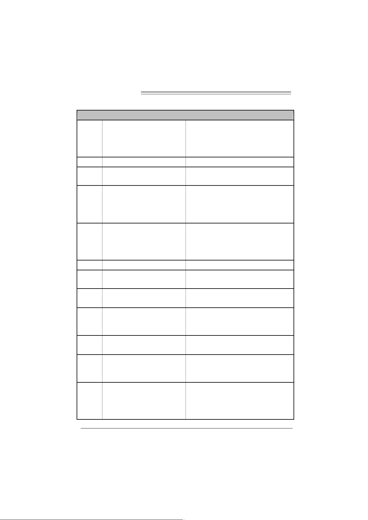
1.3 MOTHERBOARD FEAT URES
SPEC
LGA 775
CPU
FSB Support 533 / 800 / 1066 / 1333 MHz
Chipset
Super I/O
Main
Memory
Graphics GMA 3100 Max S hared Video Memory is 256MB
IDE Integrated IDE Controller
SA TA 2 I nt e gr at ed S eri a l AT A C ont r ol l er
LAN
Sound
Codec
On Board
Connector
Intel Core2Duo / Core2Quad / Celeron 4xx
/ Pentium D / Pentium 4 / Celeron D
processor
Int el G31
Intel ICH7
ITE 8712F
Provides the mos t commonly used legacy
Sup er I /O funct ionali t y.
Low Pin Count Interfac e
DIMM Slots x 2
Eac h DIMM s upports 256MB / 512MB /
1GB / 2GB DDR2
Max Memory Capicity 4GB
Realtek RTL 8101E / 8102E /
8111C (optional )
ALC662
PCI slot x2 Supports PCI expansion cards
PCI Express x 16 slot x1 Supports PCI-E x16 expansion cards Slots
PCI Express x 1 slot x1 Supports PCI-E x1 expansion cards
Floppy connector x1 Each connector supports 2 Floppy drives
Printer Port Connector x1 Each connector supports 1 Printer port
IDE Connector x1 Each connector supports 2 IDE device
SATA Connector x4 Each connector supports 1 SATA devices
Supports Hyper-Threading / Execute Disable B it /
Enhanced Intel SpeedStep® / Intel Architecture-64 /
Extended Memory 64 Tec hnol ogy / Virtualization
Tec hnology
Environment Control initiatives,
Hardware Monitor Controller
Fan Speed Controller
ITE's "Smart Guardian" function
Dual Channel Mode DDR2 memory module
Supports DDR2 800/667
Supports DDR2 533 (with FSB 533/1066 CPU)
Registered DIMM and ECC DIMM is not supported
Ultra DMA 33 / 66 / 100 Bus M ast er Mode
supports PIO Mode 0~ 4
Data transfer rates up to 3.0 Gb/s.
SATA Version 2.0 specificat ion compliant
10 / 100 Mb/s / 1Gb/s aut o negotiation (Gigabit
bandw idt h is for Realtek R TL 8111C only)
Half / Full duplex capability
5.1 channels audio out
High Defi ni tion Audio
2
Page 5
SPEC
Front Panel Connector x1 Supports fr ont panel facilities
Front Audi o Connector x1 Supports front panel audio function
CD-in Connector x1 Supports CD audio-in functi on
S/PDIF out connector x1 Supports digit al audio out function
CPU Fan header x1 CPU Fan power s upply (with Smart Fan function)
System Fan header x1 System Fan Power supply
Cl ear CMOS header x1 Rest ore C MOS data to fact ory default
USB connector x2 Each connector supports 2 front panel USB ports
Power Connector (24pin) x1 Connects to Power supply
Pow er Connect or (4pin) x1 C onnects to Power s upply
PS/2 Keyboard x1
PS/2 Mouse x1
Back Panel
I/O
Board S ize 195 (W) x 244 (L) mm
OS S upport Windows 2000 / X P / V ISTA
S e ri a l P ort x 1
VGA port x1
LAN port x1
USB Port x4
Audio Jack x3
G31-M7
Connects to PS/2 Keyboard
Connects to PS/2 Mouse
Pr ovi de RS- 232 Seria l c onnectio n
Connec t to D-SUB moni tor
Connec t to RJ-45 ether net c able
Connect to USB devices
Provide Audio-In/O ut and microphone c onnection
Biostar Reserves the right to add or remove support for
any OS with or without notice
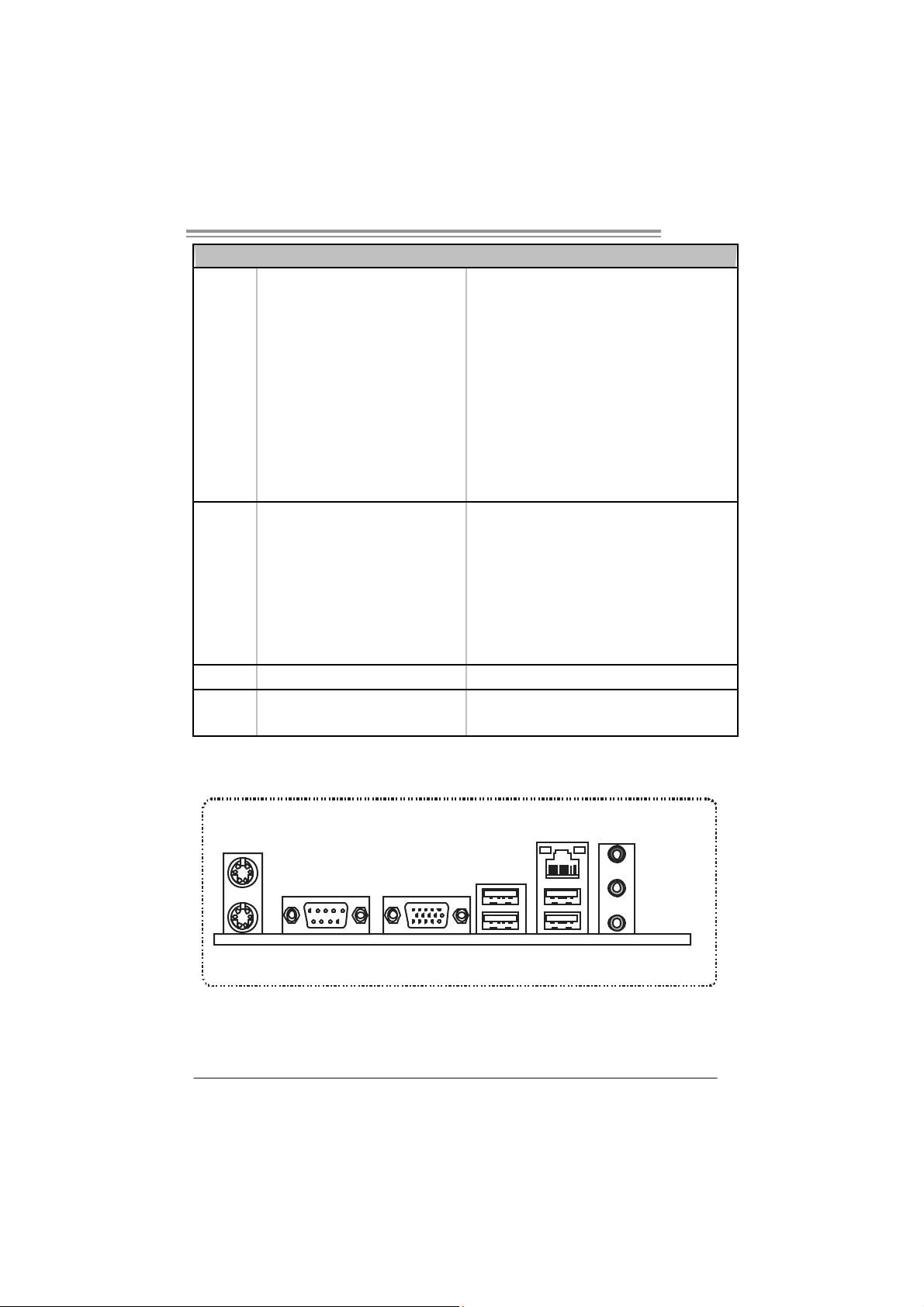
1.4 R
PS/2
Mouse
PS/2
Keyboard
Since t he au dio c hip s upports H i g h Defi ni ti on A udi o Specific atio n, the func tion of eac h a udi o
jack c an be d efine d b y sof tware. T he in put / out put fu nc ti o n of e ach au di o j ac k l isted ab o ve
represe nts th e def ault s etti ng . Ho we ver, w he n c o nnec ting e xt er nal mi croph on e to th e a udi o port ,
pleas e use t he Line In ( blue) an d Mic In (Pi nk) au dio jac k.
EAR PANEL CONNECT ORS
COM1 VGA
LA N
Line In/
Surround
Line Out
Mic In 1/
Bass/ Center
USBX2USBX2
3
Page 6
Motherboard Manual
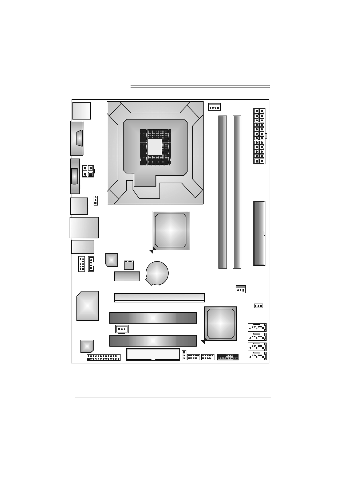
1.5 MOTHERBOARD LAYOUT
JKB MS1
J
C
O
M
1
JVGA1
JATXPWR2
JUSB2
JRJ45 USB1
JAUDIO1
JAUDIOF1
J CDI N 1
JUSBV1
LAN
BI O S
PEX1_1
LGA775
CPU1
Intel
G31
BAT 1
JCFAN1
JATXPWR1
DDR2_B1
DDR2_A1
IDE1
S uper
I/ O
JSPDIF_OUT1
Codec
Not e: ■ represents the 1st pin.
4
PE X16 _1
PCI1
PCI2
FDD1
JUSBV2
Intel
ICH7
JUSB4JUSB3
JPA NEL 1
JSFAN1
SATA4
SATA3
SATA2
SATA1
JCMOS1
Page 7
CHAPTER 2: HARDWARE INSTALLATION
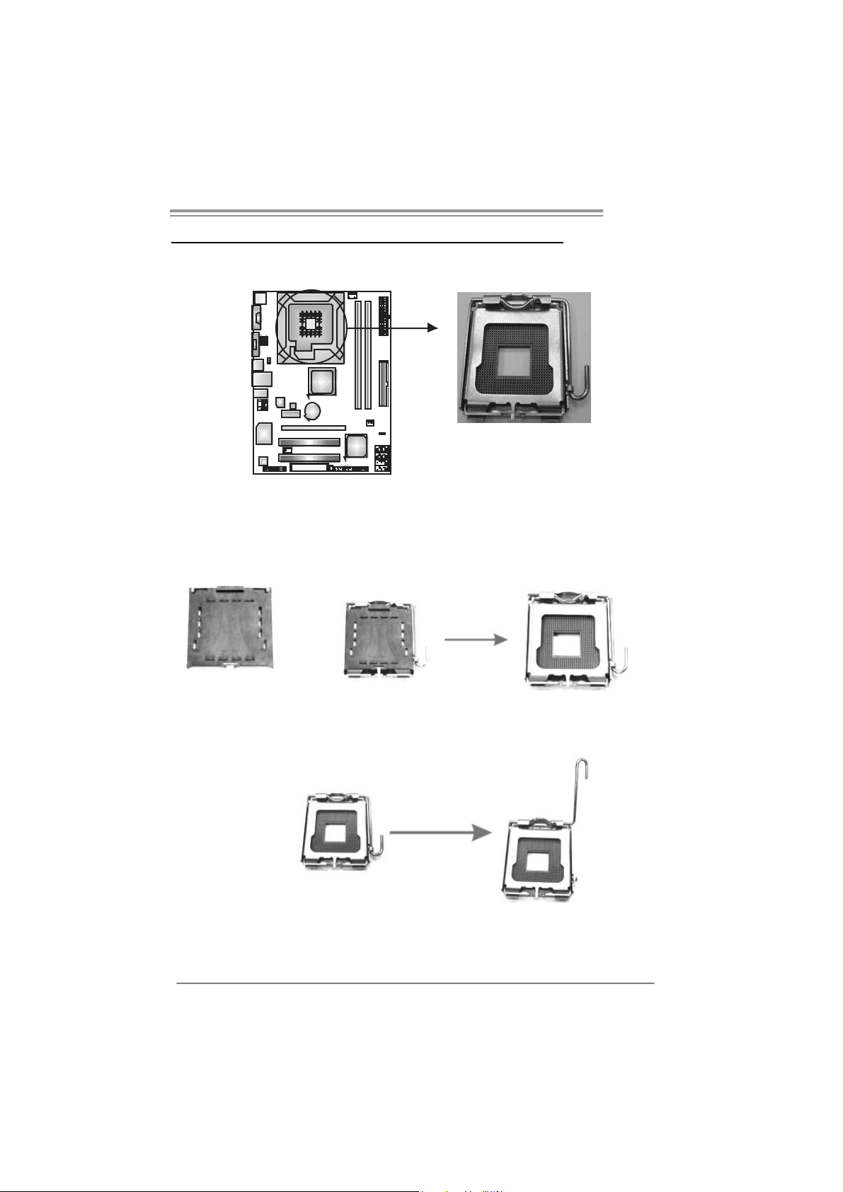
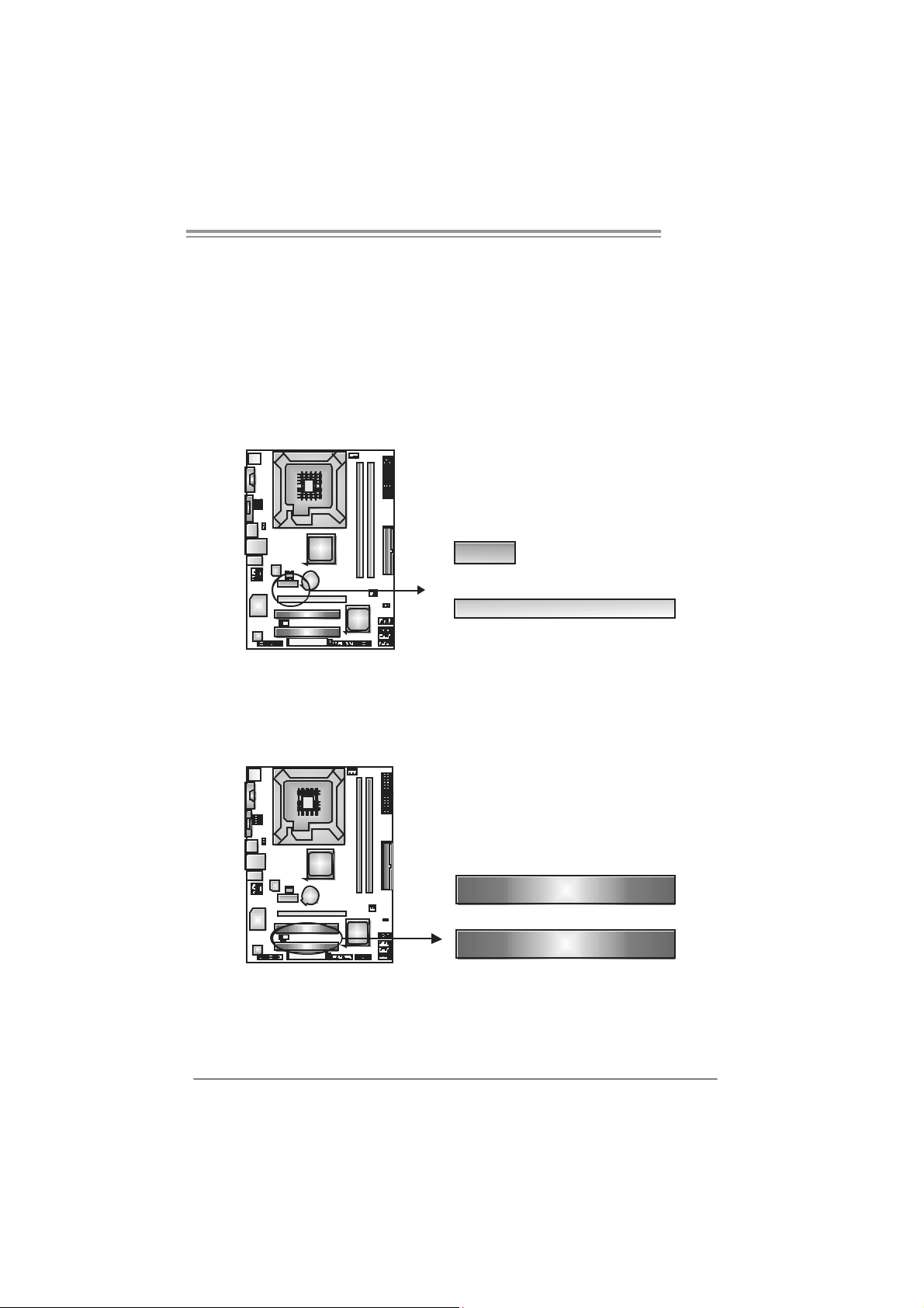
2.1 I
NST ALLING CENTRAL PROCESSING UNIT (CPU)
G31-M7
Special Notice:
Remove Pin Cap before installation, and make good preservation
for future use. When the CPU is removed, cover the Pin Cap on the
empty socket to ensure pin legs won’t be damaged.
Pin-Cap
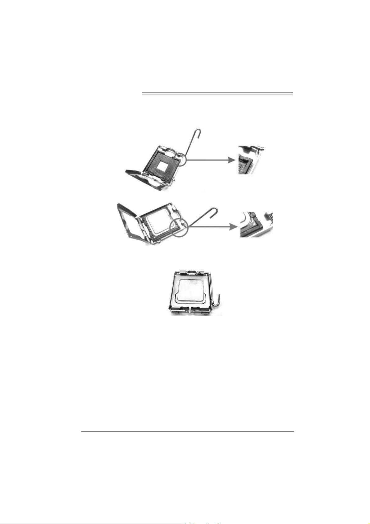
Step 1: Pull the socket locking lever out from the socket and then raise
the lever up to a 90-degree angle.
5
Page 8
Motherboard Manual
Step 2: Look for the triangular cut edge on socket, and the golden dot on
CPU should point forwards this triangular cut edge. The CPU will
fit only in the correct orientation.
Step 2-1:
Step 2-2:
Step 3: Hold the CPU down firmly, and then lower the lever to locked
position to complete the installation.
Step 4: Put the CPU Fan and heatsink assembly on the CPU and buckle it
on the retention frame. Connect the CPU FAN power cable into
the JCFAN1. This completes the installation.
6
Page 9
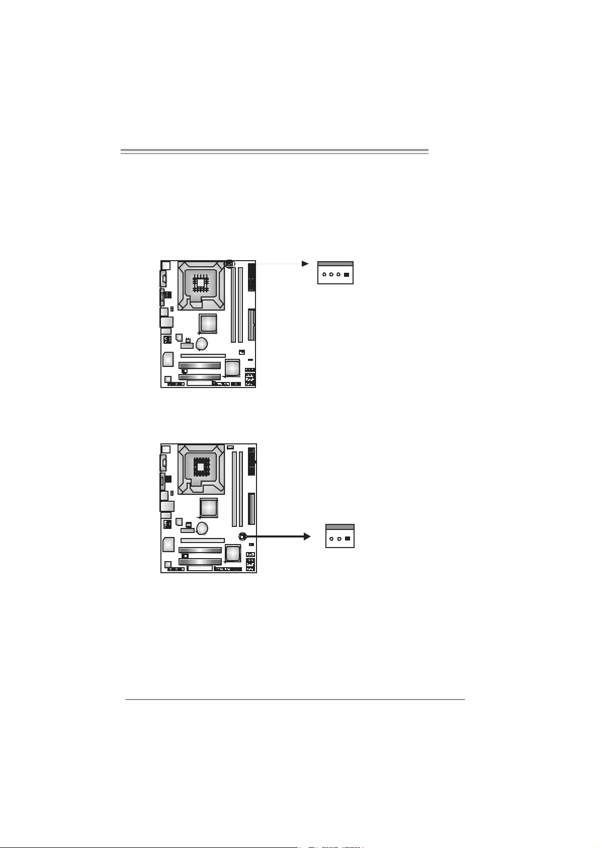
2.2 FAN HEADERS
These fan headers support cooling-fans built in the computer. The fan
cable and connector may be different according to the fan manufacturer.
Connect the fan cable to the connector while matching the black wire to
pin#1.
JCFAN1: CPU Fan Heade r
14
JC FAN1
JSFAN1: System Fan Header
JSFAN1
Pin
Pin
G31-M7
Assignment
1 Ground
2 Power
3 FAN RPM
rate sense
4 Smart Fan
Control
Assignment
1 Ground
2 +12V
3 FAN RPM
rate sense
13
Note:
The J CFAN1 su ppor t 4-pi n hea d co nn ector and J SFAN1 s uppor t 3-pin he ad c onnect or.
When co nnec ti ng wi t h wi r es o nto c on nect or s , pl e ase not e that t he re d wire is th e p ositi ve
and should be c onnec ted to pin #2, and t he blac k wir e is Gr ound an d should be
conn ecte d t o GND .
7
Page 10

Motherboard Manual
2.3 INSTALLING SYSTEM MEMORY
A. DD R2 module
DDR2_B1
DDR2_A1
1. Unlock a DIMM slot by pressing the retaining clips outward. Align a
DIMM on the slot such that the notch on the DIMM matches the
break on the Slot.
2. Insert the DIMM vertically and firmly into the slot until the retaining
chip snap back in place and the DIMM is properly seated.
8
Page 11
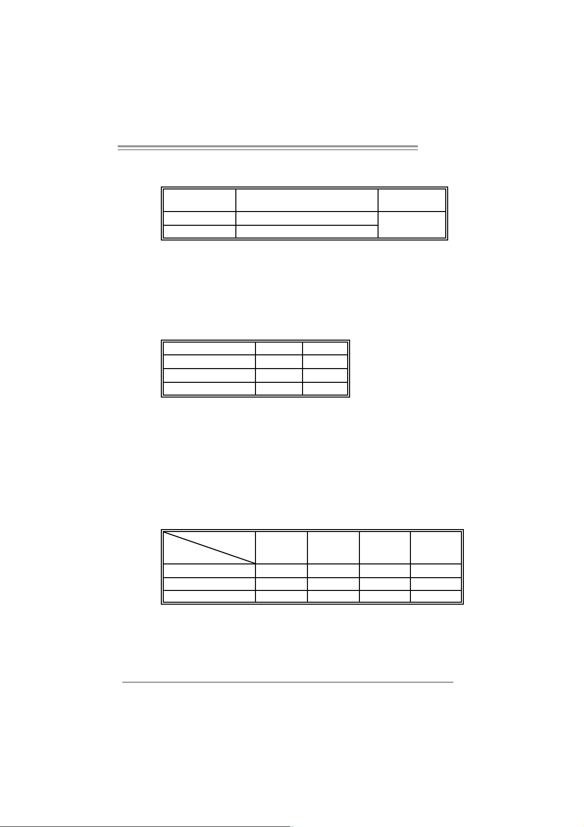
B. Memory Capacity
G31-M7
DIMM Socket
Location
DDR2_A1 256MB/512MB/1GB/2GB
DDR2_B1 256MB/512MB/1GB/2GB
DDR2 Module
To t a l M e m o r y
Size
Max is 4B.
C. D ual Ch ann el Memory In stalla tion
To trigger the Dual Channel function of the motherboard, the memory
module must meet the following requirements:
Install memory module of the same density in pairs, shown in the
following table.
Dual Channel Status
Disabled O X
Disabled X O
Enabled O O
DDR2_A1
DDR2_B1
(O means memory installed, X means memory not installed.)
The DRAM bus width of the memory module must be the same(x8 or
x16)
D. FSB Supporting Table
According to the FSB frequency of the installed CPU, the motherboard
could suppo rt DDR2 533/667/800 modules. Please refer to the table
below to find out the proper RAM module that fits the FSB of the
installed CPU.
FSB of CPU
FSB 533 FSB 800 FSB 1066 FSB1333
DDR2 Module
DDR2 533 O X O X
DDR2 667 O O O O
DDR2 800 O O O O
(O means supported, X means not supported.)
9
Page 12
Motherboard Manual
2.4 CONNECT ORS AND SLOTS
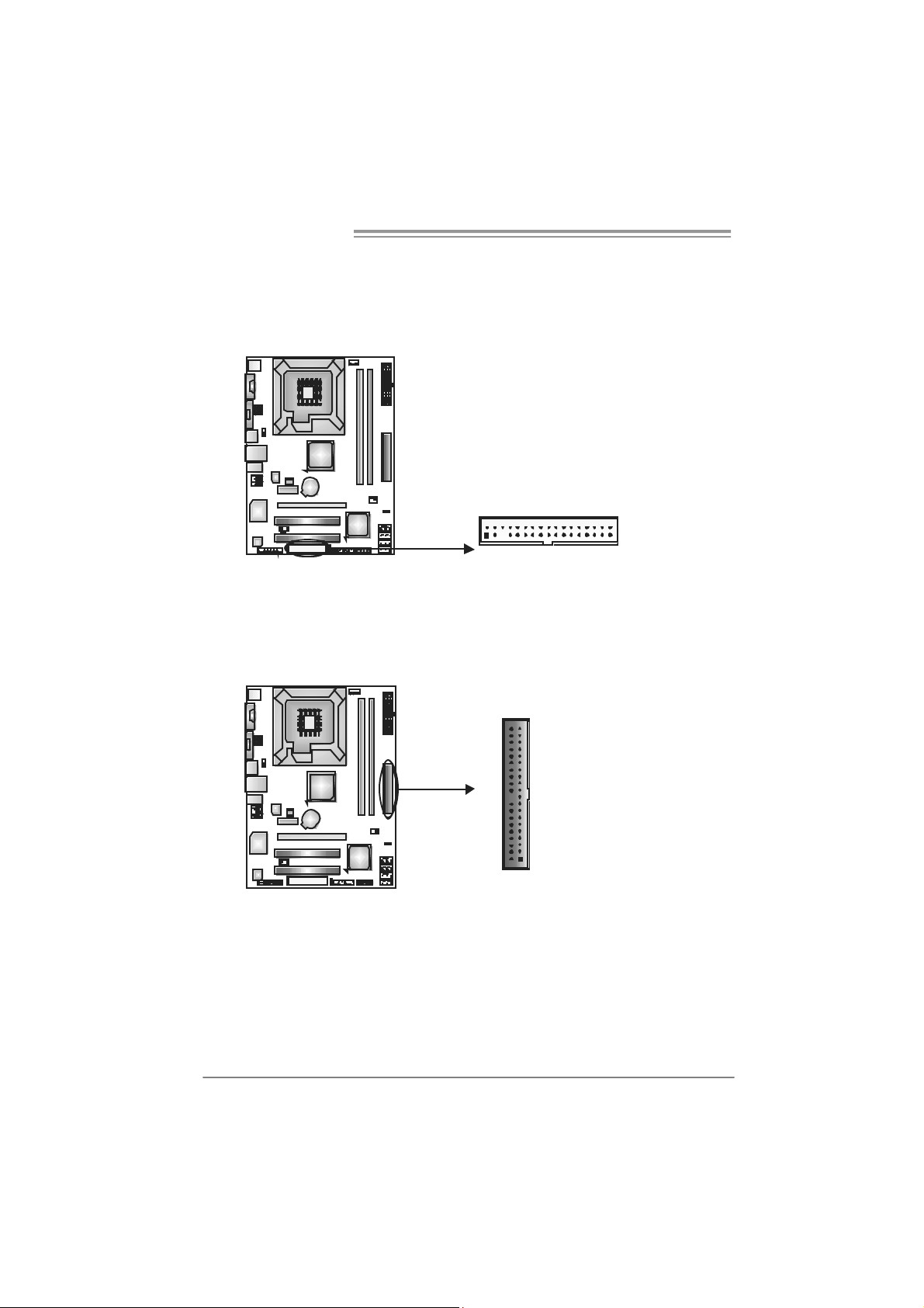
FDD1: Floppy Di sk C onnector
The motherboard prov ides a standard floppy disk connector that supports 360K,
720K, 1.2M, 1.44M and 2.88M floppy disk ty pes. This connector supports the
prov ided f loppy drive ribbon cables.
234
133
ID E1: Hard Disk Conne ctor
The motherboard has a 32-bit Enhanced PCI IDE Controller that prov ides PI O
Mode 0~4, Bus Master, and Ultra DMA 33/66/100 functionality.
The IDE connector can connect a master and a slave drive, so you can connect
up to two hard disk driv es.
IDE1
40
2
39
1
10
Page 13
PEX16_1: PCI-Express x16 Slot
- PCI-Ex press 1.0a compliant.
- Maximum theoretical realized bandwidth of 4GB/s simultaneously per
direction, f or an aggregate of 8GB/s totally.
PEX1_1: PCI-Express x1 Slot
- PCI-Ex press 1.0a compliant.
- Data transf er bandwidth up to 250MB/s per direct ion; 500MB/s in total.
- PCI-Ex press supports a raw bit-rate of 2.5Gb/s on the data pins.
- 2X bandwidth ov er the tradit ional PCI architecture.
PEX1_1
PEX16_1
PCI1~PC I2: Peripheral Component Interconnect Sl ots
This motherboard is equipped with 2 standard PCI slots. PCI stands f or
Peripheral Component Interconnect, and it is a bus standard for expansion
cards. This PCI slot is designated as 32 bits.
G31-M7
PCI1
PCI2
11
Page 14

Motherboard Manual
CHAPTER 3: HEADERS & JUM PERS SETUP
3.1 H
The illustration shows how to set up jumpers. When the jumper cap is
placed on pins, the jumper is “close”, if not, that means the jumper is
“open”.
OW T O SET U P JUMPERS
Pin opened Pin closed Pin1-2 closed
3.2 D
JPANEL1: Front Panel Header
ET AIL SET T I NG S
This 16-pin connector includes Power-on, Reset, HDD LED, Power LED, and
speaker connection. It allows user to connect the PC case’s front panel switch
functions.
PWR_LED
On/ Off
-
9
1
Pi n Assignment Func tio n P in Ass ignme nt Functio n
1 +5V 9 N/A
2 N/A 10 N/A
3 N/A 11 N/A N/A
4 Speaker
5 HDD LED (+) 13 P ower LED (+)
6 HDD LED (-)
7 Ground 15 Power button
8 Reset control
Speaker
Connector
Hard drive
LED
Reset button
++
-
+
SPK
12 Po we r LED (+)
14 Po we r LED (-)
16 Ground
RST
HLE D
16
8
N/A
Power LED
Power-on button
12
Page 15

J A TXP W R1 : A TX P o we r Sou rce C onne cto r
This connector allows user to connect 24-pin power connector on the ATX
power supply.
G31-M7
12
1
Pi n Assignment Pi n Ass ignme nt
24
13
13 +3.3V 1 + 3.3V
14 -12V 2 + 3.3V
15 Gr oun d 3 Gr oun d
16 PS_ON 4 + 5V
17 Gr oun d 5 Gr oun d
18 Gr oun d 6 + 5V
19 Gr oun d 7 Gr oun d
20 NC 8 PW_ OK
21 +5V 9 Stand b y Volt ag e+5V
22 +5V 10 +12V
23 +5V 11 +12V
24 Gr oun d 12 + 3.3V
J A TXP W R2 : A TX P o we r Sou rce C onne cto r
By connecting this connector, it will provide +12V to CPU power c ircuit.
Pin
1234
Assignment
1 +12V
2 +12V
3 Ground
4 Ground
Note:
Befor e p ow er o n the s yst em, pl eas e make sur e th at b oth J AT XP WR1 and JAT XP WR 2
conn ector s ha ve b ee n pl ug ged- i n.
13
Page 16

Motherboard Manual
JUSB3/JUSB4: Headers for USB 2.0 Ports at Front Panel
This motherboard provides 2 USB 2.0 headers, which allows user to connect
additional USB cable on the PC front panel, and also can be connected with
internal USB devices, like USB card reader.
JUSB3 JUSB4
210
Pin Assignment
1 +5V (fused)
2 +5V (fused)
3 USB4 USB5 USB+
6 USB+
7 Ground
8 Ground
9 Key
10 NC
19
JAUDIO F1: Front Panel Audio Heade r
This header allows user to connect the front audio out put cable with the PC front
panel. This header allows only HD audio front panel connector; AC’97 connector
is not acceptable.
Pi n Assignment
1 Mic Left in
2 Ground
3 Mic Right in
4 GPIO
10
9
1
2
5 Right line in
6 Jack Sense
7 Front Sens e
8 Key
9 Left line in
10 Jack Sens e
JCDIN1: CD-ROM Audio-in Connector
This connector allows user to connect the audio source f rom the v ariaty dev ices,
like CD-ROM, DVD-ROM, PCI sound card, PCI TV turner card etc..
Pin
Assignment
1 Left Channel
Input
2 Ground
4
1
3 Ground
4 Right
Channel
Input
14
Page 17

G31-M7
JCMOS1: Clear CMOS Header
By placing the jumper on pin2-3, it allows user to restore the BIOS saf e setting
and the CMOS data, please carefully f ollow the procedures to avoid damaging
the motherboard.
13
Pin 1-2 Close:
Normal Operation
(Default).
13
Pin 2-3 Close:
Clear CMOS data.
13
※ Clear CMOS Proce du res:
1. Remov e AC power line.
2. Set the jumper to “Pin 2-3 close”.
3. Wait f or f ive seconds.
4. Set the jumper to “Pin 1-2 close”.
5. Power on the AC.
6. Reset your desired password or clear the CMOS data.
SATA1~S ATA4: Se rial ATA Connectors
The motherboard has a PCI to SATA Controller with 4channels SATA interf ace, it
satisfies the SATA 2.0 spec and with transfer rate of 3Gb/s.
Pi n Assignment
1 Ground
2 TX +
SATA 4
SATA 3
SATA 2
SATA 1
3 TX -
4 Ground
5 RX-
6 RX+
7 Ground
147
15
Page 18

Motherboard Manual
JSPDIF_OUT1: Digital Audio out Connector
This connector allows user to connect the PCI bracket SPDIF output header.
13
J USB V1 /J USB V2: Po we r So ur ce Hea de rs fo r USB P o rts
Pin 1-2 Close:
JUSBV1: +5V for USB ports at JUSB2/JRJ45USB1.
JUSBV2: +5V for USB ports at front panel (JUSB3/JUSB4).
Pin 2-3 Close:
JUSBV1: +5V STB for USB ports at JUSB2/JRJ45USB1.
JUSBV2: +5V STB for USB ports at front panel (JUSB3/JUSB4).
Pin
Assignment
1 +5V
2 SPDIF_OUT
3 Ground
16
JUSBV1
3
1
JUSB V2
1
3
1
3
Pin 1-2 close
1
3
Pin 2-3 close
Page 19

JPRNT1: Printer Port Connector
This header allows you to connector printer on the PC.
2
G31-M7
1
25
Pin Assignment Pin As signment
1 -Strobe 14 Gr ound
2 -ALF 15 D ata 6
3 Data 0 16 Gr ound
4 -Error 17 Data 7
5 Data 1 18 Gr ound
6 -Init 19 - ACK
7 Data 2 20 Gr ound
8 -Sclti n 21 Bus y
9 Data 3 22 Gr ound
10 Groun d 23 PE
11 Data 4 24 Groun d
12 Groun d 25 SCLT
13 Data 5 26 Key
17
Page 20

Motherboard Manual
CHAPTER 4: USEFUL HELP
4.1 D
RIVER INST ALLAT ION NOT E
After you installed your operating system, please insert the Fully Setup
Driver CD into your optical drive and install the driver for better system
performance.
You will see the following window after you insert the CD
The setup guid e will auto detect you r motherboard and operating system .
Note:
If thi s win do w di dn’ t show up aft er yo u i ns er t th e Dri ver CD, pl ease use fil e br ows er to
locate and e xecute th e fi le SETU P.EXE un der your o pti cal dr i ve .
A. Driver Installation
To install the driver, please click on the Driver icon. The setup guide will
list the compatible driver for your motherboard and operating system.
Click on each device driver to launch the installation program.
B. S oftwa re In stal lation
To install the software, please click on the Software icon. The setup guide
will list the software available for your system, click on each software title
to launch the installation program.
C. Manual
Aside from the paperback manual, we also provide manual in the Driver
CD. Click on the Manual icon to browse for available manual.
Note:
You will need Acrobat Reader to open the manual file. Please download the latest version
of Acrobat Reader software from
http://www.adobe.com/products/acrobat/readstep 2.html
18
Page 21

4.2 AMI BIOS BEEP CODE
n
)
a
e
Boot Block Beep Codes
Number of Beeps Description
1 No media present. (Insert diskette in floppy drive A:)
2
3 Insert next diskette if multiple diskettes are used f or recovery
4 Flash Programming successful
5 File read error
7 No Flash EPROM detected
10 Flash Erase error
11 Flash Program error
12 “AMIBOOT.ROM” f ile size error
13
POST BIOS Beep Codes
Number of Beeps Description
1 Memory refresh timer error
3 Base memory read/write test error
6 Key board controller BAT c ommand failed
7 General exception error (processor exception interrupt error
8 Display memory error (system video adapter)
“AMIBOOT.ROM” f ile not f ound in root directory of diskette i
A:
BIOS ROM image mismatch (file layout does not match
image present in flash device)
G31-M7
Troubleshooting POST BIOS Beep Codes
Number of Beeps Troubleshooting Action
1, 3 Reseat the memory, or replace with k nown good modules.
Fatal error indicating a serious problem with the system.
Consult y our system manufacturer. Bef ore declaring the
motherboard beyond all hope, eliminate the possibility of
interference by a malf unctioning add-in card. Remov e all
expansion cards except the video adapter.
z If beep codes are generated when all other expansion
6, 7
8
cards are absent, consult y our system manufacturer’s
technical support.
z If beep codes are not generated when all other expansion
cards are absent, one of the add-in cards is causing the
malfunction. Insert the cards back into the system one at
time until the problem happens again. This will rev eal the
malfunctioning card.
If the system video adapter is an add-in card, replace or
reseat the
video adapter. If the v ideo adapter is an integrated part of t h
system board, the board may be faulty.
19
Page 22

Motherboard Manual
4.3 EXT RA INFORMAT ION
CPU Overheated
If the system shutdown automatically after power on system for
seconds, that means the CPU protection function has been activated.
When the CPU is over heated, the motherboard will shutdown
automatically to avoid a damage of the CPU, and the system may not
power on again.
In this case, please double check:
1. The CPU cooler surface is placed evenly with the CPU surface.
2. CPU fan is rotated normally.
3. CPU fan speed is fulfilling with the CPU speed.
After confirmed, please follow steps below to relief the CPU protection
function.
1. Remove the power cord from power supply for seconds.
2 . Wa i t f o r se co nd s.
3. Plug in the power cord and boot up the system.
Or you can:
1. Clear the CMOS data.
(See “Close CMOS Header: JCMOS1” section)
2 . Wa i t f o r se co nd s.
3. Power on the syste m ag ai n.
20
Page 23

BIO-Flasher
BIO-Flasher is a BIOS flashing utility prov iding y ou an easy and simple way t o
update your BIOS via USB pen drive or f loppy disk.
The BIO-F las her is b uil t in th e BIO S c hip. To e nter the ut ili ty, press <F12>
during the Power-On Self Tests (POST) procedure while booting up.
Updating BIOS with BIO-Flasher
1. Go to the website to download the latest BIOS file f or the mot herboard.
2. Then, sav e the BIOS f ile into a USB pen drive or a f loppy disk.
3. Insert the USB pen drive or the floppy disk that contains the BIOS file to the
USB port or the floppy disk drive.
4. Power on or reset the computer and then
press <F12> during the POST process.
A select dialog as the picture on the right
appears.
Select the device contains the BIOS file and
press <En ter> t o enter t he utility.
G31-M7
5. The utility will show the BIOS
f iles and their respective
inf ormat ion. Select the proper
BIOS file and press <Enter >
then <Y> to perf orm the BIOS
update process.
6. After the update process, the utility will ask y ou to reboot the system.
Press <Y> to proceed. BIOS update completes.
z This utility only allows st orage device with FAT32/16 format and single
partiti on.
z Shutting down or resetting the system while updating the BIOS will lead to
syst em bo ot fail ur e.
21
Page 24

Motherboard Manual
e
4.4 T
ROUBLESHOOT ING
1. No power to the system at all
Probable Solution
Power light don’t illuminate, f an
inside power supply does not turn
on.
2. Indicator light on key board does
not turn on.
System inoperativ e. Keyboard lights
are on, power indicator lights are lit,
and hard driv e is spinning.
System does not boot from hard disk
driv e, can be booted from optical driv e.
System only boots f rom optic al driv e.
Hard disk can be read and applications
can be used but booting from hard disk
is impossible.
Screen message says “Invalid
Configuration” or “CMOS Failure.”
Cannot boot system after installing
second hard drive.
1. Make sure power cable is
securely plugged in.
2. Replace cable.
3. Contact t echnical support.
Using even pressure on both ends of
the DIMM, press down firmly until the
module snaps into place.
1. Check cable running from disk to
disk controller board. Make sure
both ends are securely plugged
in ; c h ec k t he d r iv e ty pe i n t h e
standard CMOS setup.
2. Backing up the hard drive is
extremely important. All hard
disks are capable of breaking
down at any time.
1. Back up data and applications
files.
2. Ref ormat the hard drive.
Re-install applications and data
using backup disks.
Review system’s equipment. Make sur
correct inf ormat ion is in setup.
1. Set master/slave jumpers
correctly.
2. Run SETUP program and select
correct driv e types. Call the drive
manufacturers f or compatibility
with other drives.
22
Page 25

G31-M7
This page is intentionally left blank.
23
Page 26

Motherboard Manual
APPENDENCIES: SPEC IN OTHER LANGU AGE
GERMAN
S p e z i f ik a t io n e n
LGA 775
Intel Core2Duo / Core2Quad / Celeron 4xx
CPU
/ Pentium 4 / Pent ium D / Celeron D
Unterstützt Hyper-Threading / Execute Disable Bit /
Enhanced Intel SpeedStep® / Intel Architecture-64 /
Extended Memory 64 Tec hnol ogy / Virtualization
Proz essoren
FSB 533 / 800 / 1066 / 1333 MHz
Chipsatz
Super E/A
Arbeitss peich
er
Grafik GMA 3100 Max. 256MB gemeins am benutzter Videos peicher
IDE Integrierter IDE-Controller
SA TA I nt e gr i ert e r S eri al ATA- Controll e r
Int el G31
Intel ICH7
ITE 8712F
Bi etet die häufig verw endeten alten S uper
E/A-Funktionen.
Low Pin Count-Schnittstelle
DDR2 DIMM-S teckplätze x 2
Jeder DIMM unterstützt 256MB / 512MB /
1GB / 2GB DDR2.
M a x. 4GB A rbeit ss p eic her
Tec hnology
Umgebungskontrolle,
Hardw ar e-Überwachung
Lüft erdrehz ahl-Controller/-Überwac hung
"Smart Guardian"-Funktion von ITE
Dual-Kanal DDR2 Speichermodul
Unt erstützt DDR2 800/667
Unt erstützt DDR2 533 (w. FSB 533/1066 C PU)
registrierte DIMMs. ECC DIMMs werden nicht
unterstützt.
Ultra DMA 33 / 66 / 100 Bus M ast er-M odus
Unterstützt PIO-Modus 0~4,
Datentransferrate bis zu 3.0Gb/s
Konform mit der SATA-S pezifikation Version 2.0.
LAN
HD
Audio-Unters
tützung
24
Realtek RTL 8101E / 8102E /
8111C(optional )
ALC662
10 / 100 / 1000 M b/s Auto-Negotiation
(Gigabit-B andbreite nur beim Realtek RTL 8111C)
Halb-/ Vollduplex-Funktion
Unterstützt High-Definition Audio
5.1-Kanal-A udi oaus gabe
Page 27

Onboard-Ans
chluss
G31-M7
S p e z i f ik a t io n e n
PCI-St ec kplatz x2
PCI Express x16 Steckplatz x1 Steckplätze
PCI Express x 1-Steckplatz x1
Diskettenlaufwerkanschluss x1 Jeder Anschluss unterstützt 2 Diskettenlaufwerke
Druckeranschluss Anschluss x1 Jeder Anschluss unterstützt 1 Druckeranschluss
IDE-Anschluss x1 Jeder Anschluss unterstützt 2 I DE-Laufwerke
SATA-Anschluss x4 Jeder Anschluss unterstützt 1 SATA-Laufwerk
Fronttafelanschluss x1 Unterstützt die Fronttafelfunktionen
Front-Audioanschluss x1 Unterstützt die Fronttafel-Audioanschlussfunktion
CD-IN-Anschluss x1 Unterstützt die CD Audio-In-Funktion
S/PDIF- Ausgangsanschluss x1 Unterstüt zt die digit ale A udioaus gabefunkti on
CPU-Lüfter-Sockel x1
System-Lüfter-Sockel x1 System-Lüfter-Stromversorgungsanschluss
"CMOS löschen"-S ockel x1
US B-A nschluss x2
CPU-Lüfterstromversorgungsanschluss (mit Smart
Fan-Funktion)
Jeder Anschluss unterstützt 2
Fronttafel-USB-Anschlüsse
Stromanschluss (24-polig) x1
Stromanschluss (4-polig) x1
PS/2-Tastatur x1
PS/2-Maus x1
Rückseiten-E
/A
Platinengröße 195 mm (B) X 244 mm (L )
OS-Unt erstüt
zung
Serieller A nsc hluss x1
VGA-Anschluss x1
LAN-Ansc hluss x1
US B-A nschluss x4
Audi o ansc hluss x 3
Wi ndows 2000 / XP / VISTA
Biostar behält sich das Recht vor, ohne Ankündigung
die Unterstützung für ein Betriebss ystem
hinz uzufügen oder zu entfernen.
25
Page 28

Motherboard Manual
FRANCE
LGA 775
UC
Bus frontal 533 / 800 / 1066 / 1333 M Hz
Chipset
Super E/S
Mémoire
principale
Processeurs Intel Core2Duo / Core2Quad
/ Celeron 4xx / Pentium 4 / Pentium D /
Celeron D
Int el G31
Intel ICH7
ITE 8712F
Four ni t l a fonctionnalit é de S uper E/S
patrimoniales la plus utilisée.
Interface à faible compte de broches
Fentes DDR2 DIM M x 2
Chaque DIMM prend en c harge des DDR 2
de 256Mo / 512M o / 1Go / 2Go
Capacité mémoire maximale de 4Go
SPEC
Prend en charge les technologies Hyper-Threading /
d'exéc ution de bit de désactivation / Intel SpeedStep®
optimisée/ d'architecture Intel 64 / de mémoire
étendue 64 / de virtualisation
Initiatives de contrôle environnementales,
Moniteur de matériel
Contrôleur /moniteur de vitess e de ventilateur
Fonction "Gardien intelligent" de l'ITE
Module de mémoire DDR2 à mode à double voie
Prend en charge la DDR2 800/667
Prend en charge la DDR2 533 (w. FSB 533/1066 C PU)
Les DIMM à registres et DIMM avec code correcteurs
d'erreurs ne sont pas prises en charge
Graphiques GMA 3100 Mémoire vidéo partagée maximale de 256 M o
IDE C ontrôleur I DE intégré
SA TA
LAN
Prise en
charge
audio HD
Fentes
Cont r ôl eur Se rial ATA intégré
Realtek RTL 8101E / 8102E /
8111C(optional )
ALC662
Fente PCI x2
Fente PCI Express x16 x1
Fente PCI Express x1 x1
Mode principale de Bus Ultra DMA 33 / 66 / 100
Prend en charge le mode PIO 0~4,
Taux de transfert jusqu'à 3.0Go/s.
Conforme à la spécification SATA Version 2.0
10 / 100 / 1000 M b/s négoci ation automat ique (La
bande passante Gigabit est pour le Realtek R TL 8111C
uniquement)
Half / Full duplex capability
Prise en charge de l'audio haute définition
Sortie audio à 5. 1 voies
26
Page 29

Connec t eur de disquette x1
Connec t eur de Port d' imprimante x1 Chaque connector prend en charge 1 Port d'impr imante
Connec t eur I DE x1
Connec te ur SATA x4
Connecteur du panneau avant x1 Prend en charge les équipements du panneau avant
Connect eur Audio du panneau avant x1 Prend en c harge la fonction audio du panneau avant
Connec t eur
embarqué
E/S du
panneau
arrière
Dim ensions
de la c arte
Support S E Windows 2000 / X P / V ISTA
Connec teur d'entrée CD x1 Prend en c harge la fonction d'entrée audio de CD
Connecteur de sortie S/PDIF x1 Prend en charge la fonction de sortie audio numérique
Embase de ventil ateur UC x1
Embase de ventilateur système x1 Alimentation électrique du ventilateur système
Embas e d'effacement CMO S x1
Connec t eur USB x2
Connec teur d'alimentation x1
(24 broc hes)
Connec teur d'alimentation x1
(4 broches)
Clavier PS/2 x1
Souris PS/2 x1
Port série x1
Port VGA x1
Port LAN x1
Port USB x4
Fiche audio x3
195 mm (l ) X 244 mm (H)
G31-M7
SPEC
Chaque connector prend en charge 2 lecteurs de
dis quettes
Chaque connec teur prend en charge 2 périphériques
IDE
Chaque connec teur prend en charge 1 périphérique
SA TA
Alimentation électrique du ventilateur UC (avec fonction
de ventilateur intelligent)
Chaque connec teur prend en charge 2 ports USB de
panneau avant
Biostar se réserve le droit d'ajouter ou de supprimer le
support de S E avec ou sans préavis.
27
Page 30

Motherboard Manual
ITALIAN
LGA 77 5
SPECIFICA
Suppor to di Hyper -Threadi ng / Execute Dis able
CPU
FS B 533 / 800 / 1066 / 1333 MHz
Chipset
Super I/O
Memoria
principal e
Grafic a GMA 31 00 La memoria vide o con divi s a m assim a è di 25 6MB
IDE Controller IDE integrato
SATA Controller Serial ATA integrato
Processore Intel Core2Duo /
Core2Quad / Cel er o n 4xx / Pent i um 4
/ Pentium D / Celer on D
Int el G31
Intel ICH7
ITE 8712F
Fornisce le funzio nalità leg acy Super
I/O usat e pi ù com u nemente.
Interfaccia LPC (L ow Pin Count)
Al loggi DI MM DDR 2 x 2
Ci as cun DIMM s u pporta DDR 2 25 6MB
/ 512MB / 1GB / 2GB
Capacità massima della memoria 4GB
Bit / Enhanced Intel SpeedStep® / Architettura
Int el 6 4 / Tec nol ogia Exte nde d Memory 64 /
Tecnologia Virtualization
Funzioni di co ntrollo dell’ambiente:
Monitoraggio h ardware
Controller / Monitoraggio velocità ventolina
Funz ione "Sm ar t G uardi an" di I TE
Modulo di memoria DDR2 a c an ale dop pio
Supporto di DDR 2 800/ 667
Supporto di DDR2 533 (w. FSB 533/1066 CPU)
DIMM registrati e DIMM ECC non sono supportati
Modalit à Bus Mas t er Ultra DMA 33 / 66 / 100
Suppor to m odalit à PIO Mode 0- 4
Velocità di trasferim ent o dei dat i fi no a 3.0Gb /s.
Compatibile specifiche SATA Versione 2.0.
LAN
Suppor to
audio HD
28
Realtek RTL 8101E / 8102E /
8111C(optional )
ALC662
Alloggio PCI x2
Al loggio PCI Ex press x1 6 x1 Alloggi
Al loggio PCI Ex press x1 x1
Negoziazione autom at i c a 10 / 10 0 / 100 0 Mb /s
(la lar g hez z a di ba nda Gigabit è sol o per Realt ek
RTL 81 11C)
Capacità Half / Full Duplex
Supporto audio High-Definition (HD)
Uscita audio 5.1 canali
Page 31

(
Connettori
su scheda
G31-M7
SPECIFICA
Connettore fl o ppy x1 Ciascun conn ettore sup port a 2 uni t à Flopp y
Connettore Port a stampa nte x1 Cias c un c onnet t ore s up port a 1 Port a stampant e
Connettore I DE x1 Cias c un c onn ett ore sup por ta 2 unità IDE
Connettore S A TA x4 Ci as c un c onnettore sup port a 1 uni t à SATA
Connettore pannello frontale x1 Supporta i servizi del pannello fr ontale
Connettore audio frontale x1 Supporta la funzione audi o pannello frontale
Connettore C D-i n x1 Support a la funz i one i nput au dio C D
Connettore outp ut S PDI F x1 Support a la funz i one d’out p ut a udi o digitale
Collettore ventolina CPU x1
Alimentazione ventolina C PU
Fan)
Collettore ventolina sistema x1 Alimentazione ventolina di sistema
Collettore cancellazione CMOS x1
Ciascun connettore supporta 2 porte USB
Connettore USB x2
pannello frontale
Connettore alimentazione x1
(24 pin)
Connettore alimentazione x1
(4 pin)
c on f unz io ne S m art
I/O
pannello
posteriore
Dim ens ion
i scheda
Sistemi
operativi
support at i
Ta s t ie ra P S/ 2 x 1
Mouse PS/2 x1
Porta seriale x1
Porta VGA x1
Porta LAN x1
Porta USB x4
Connettore au dio x3
19 5 m m (l ar gh ezza) x 24 4 mm
(altezza)
Windows 2000 / XP / VISTA
Biostar si riserva il diritto di aggiungere o
rimuovere il supporto di qualsiasi sistema
operativo s e nz a pre avviso.
29
Page 32

Motherboard Manual
SPANISH
LGA 775
Especificación
Admite Hyper-Threading / Bit de deshabilitación de
CPU
FSB 533 / 800 / 1066 / 1333 MHz
Conjunto de
chips
Súper E/S
Memoria
principal
Gráficos GMA 3100 Memoria máxima de vídeo comparti da de 256MB
IDE Controlador IDE integrado
Procesador Intel Core2Duo / Core2Quad /
Celeron 4xx / Pentium 4 / Pentium D /
Celeron D
Int el G31
Intel ICH7
ITE 8712F
Le ofrece las funcionalidades heredadas de
uso más c omún Súper E/S.
Interfaz de cuenta Low Pin
Ranuras DIMM DDR2 x 2
Cada DIMM admi t e DDR de 256MB /
512MB / 1GB / 2GB
Capacidad máxima de memoria de 4GB
ejecución / Intel SpeedStep® Mejorado / Intel
Architect ure-64 / Tecnología Extended Memory 64 /
Tecnología de virtualización
Iniciativas de control de entorno,
Monitor hardware
Controlador/monitor de veloc idad de vent ilador
Función "Guardia inteligente" de ITE
Módul o de memoria DDR2 de canal Doble
Admite DDR2 de 800/667
Admite DDR2 de 533 (w. FSB 533/1066 CPU)
No admite DIMM registrados o DIMM compatibles con
ECC
Modo bus maestro Ultra DMA 33 / 66 / 100
Soporte los Modos PIO 0~4,
SATA Controlador ATA Serie Integrado
Red Local
Soporte de
sonido HD
Realtek RTL 8101E / 8102E /
8111C (opcional)
ALC662
Ranura PCI X2
Ranura PCI Express x16 X 1 Ranuras
Ranura PCI express x 1 X 1
30
Tasas de transferencia de hasta 3.0 Gb/s.
Compatible con la versión SATA 2. 0.
Negociación de 10 / 100 / 1000 Mb/s (el anc ho de
banda Gi gabit es únicament e para Realtek R TL 8111C )
Funciones Hal f / Full dúplex
Soporte de sonido de Alta Definic ión
Salida de s onido de 5. 1 c anales
Page 33

Conectores
en placa
G31-M7
Especificación
Conect or disco flexible X 1 Cada conector s oporta 2 unidades de disc o flexible
Conect or Puert o de im presora X1 Cada c onector soporta 1 Puerto de impresora
Conector IDE X1 Cada conector soporta 2 dispositivos IDE
Conector SATA X4 Cada conector soporta 1 dispositivos SATA
Conector de panel frontal X1 Soporta instalaciones en el panel frontal
Conec t or de soni do front al X1 Soporta func iones de soni do en el panel frontal
Conector de entrada de CD X1 Soporta función de entrada de s onido de CD
Conect or de salida S/PDIF X1 Soporta función de salida de sonido digital
Cabecera de ventilador de CPU X 1 Fuente de alimentación de ventilador de CPU (c on
func ión S mart Fa n)
Cabecera de ventilador de s istema X1 Fuent e de alimentación de ventilador de s istema
Cabecera de borrado de CMOS X1
Conector USB X2 Cada conector soporta 2 puertos USB frontales
Conector de alimentación X1
(24 pat illas)
Panel
trasero de
E/S
Ta m añ o de
la placa
Soporte de
sistema
operat ivo
Conector de alimentación X1
(4 patillas)
Te c l ado PS / 2 X 1
Ratón PS/2 X1
Puerto serie X1
Puerto VGA X1
Puerto de red local X1
Puerto USB X4
Conector de sonido X3
195 mm. (A ) X 244 Mm. (H)
Wi ndows 2000 / XP / VISTA
Biostar se reserva el derecho de añadir o retirar el
soporte de cualquier SO con o sin aviso previo.
31
Page 34

Motherboard Manual
PORT UGUESE
ESPECIFICAÇÕES
LGA 775
CPU
FSB 533 / 800 / 1066 / 1333 MHz
Chipset
Es pec ificaçã
o Super I/O
Memória
principal
Plac a
gráfica
IDE Controlador IDE integrado
SATA Controlador Serial ATA integrado
LAN
Suporte
para áudio
de alta
definição
Processador Intel Core2Duo /
Core2Q uad / Celeron 4xx / Pentium 4 /
Pentium D / Celeron D
Int el G31
Intel ICH7
ITE 8712F
Proporciona as funcionalidades mais
utilizadas em termos da es pec i ficação
Super I/O.
Int erfac e LPC (Low Pin Count).
Ranhuras DIMM DDR2 x 2
Cada módulo DIMM suporta uma
memória DDR2 de 256 MB / 512 MB / 1GB
/ 2GB
Capacidade máxima de m emória:4 GB
GMA 3100 Memória de ví deo máxima partil hada: 256 MB
Realtek RTL 8101E / 8102E /
8111C(opcional)
ALC662
Suporta as tecnologias Hyper-Threading / Exec ute
Disable Bit / Enhanced Intel SpeedStep® / Intel
Ar quitecture -64 / Extended M emory 64 / Virt ualization
Iniciativas para controlo do ambiente
Monitoriz ação do hardware
Controlador/Monitor da veloc idade da ventoinha
Função "Smart Guardian" da ITE
Módulo de mem ória DDR2 de canal duplo
Suporta módul os DDR2 800/667
Suporta módul os DDR2 533 (w. FSB 533/1066 CPU)
Os módulos DIMM registados e os DIMM ECC não são
suportados
Modo Bus master Ul tra DMA 33 / 66 / 100
Suporta o modo PIO 0~4,
Velocidades de transmissão de dados até 3.0 Gb/s.
Compatibilidade com a especificação SATA versão 2.0.
Auto negociaç ão de 10 / 100 / 1000 Mb/s (a largura de
banda Gigabit refere-se apenas à especificação Realtek
RTL 8111C)
Capacidade semi/full-duplex
Suporta a especificaç ão High-Definition Audio
Saída de áudio de 5.1 canais
32
Page 35

Conectores
na plac a
G31-M7
ESPECIFICAÇÕES
Ranhura PCI x2
Ranhura PCI Express x16 x1 Ranhuras
Ranhura PCI Express x 1 x1
Conect or da unidade de disquet es x1 Cada c onector suporta 2 unidades de disquetes
Conector da para impressora x1 Cada c onector suporta 1 Porta para impress ora
Conector IDE x1 Cada conector suporta 2 dispositivos IDE
Conector SATA x4 Cada conector suporta 1 dispositivo SATA
Conec t or do painel frontal x1 Para s uporte de várias funções no pai nel frontal
Conector de áudio frontal x1 Suporta a função de áudio no painel frontal
Conector para ent rada de CDs x1 Suport a a entrada de áudio a partir de CDs
Conector de s aída S/PDIF x1 Suporta a saída de áudio digital
Conec t or da vent oinha da CPU x1
Conec t or da vent oinha do sistema x1 Alim entação da vent oi nha do sistema
Conector para limpeza do CMOS x1
Conector USB x2 Cada conector suporta 2 portas USB no painel frontal
Conector de alimentação x1
(24 pinos)
Conector de alimentação x1
(4 pinos)
Aliment ação da ventoinha da CPU (com a funç ão Smart
Fan)
Entradas/S
aídas no
painel
traseiro
Tam anho
da placa
Sistemas
operat ivos
suportados
Te c l ado PS / 2 x 1
Rato PS/2 x1
Port a séri e x1
Porta VGA x1
Porta LAN x1
Porta USB x4
Tomada de áudio x3
195 mm (L ) X 244 mm (A)
Wi ndows 2000 / XP / VISTA
A Biostar reserva-se o direito de adicionar ou remover
suporte para qualquer sistema operativo com ou sem
avis o prévio.
33
Page 36

Motherboard Manual
POLISH
LGA 775
Procesor
Procesor Intel Core2Duo / Core2Q uad /
Celeron 4xx / Pentium 4 / Pentium D /
SPEC
Obsługa Hyper-Threading / Execute Disable Bit /
Enhanced Intel SpeedStep® / Intel Architecture-64 /
Extended Memory 64 Tec hnol ogy / Virtualization
Celeron D
FSB 533 / 800 / 1066 / 1333 MHz
Chipset
Pamięć
główna
Grafika GMA 3100
Super I/O
I DE Z i nt e g ro w an y k o nt r ol e r I D E
SATA Zint egrow any kontroler Serial A TA
Int el G31
Intel ICH7
Gniaz da DDR 2 DIMM x 2
Każ de gniazdo DIMM obs ługuje moduły
256MB / 512MB / 1GB / 2GB
Maks. wielkość pa mi ęci 4GB
ITE 8712F
Zapew nia najbardziej powszechne funkc je
Super I/O.
Int erfejs Low Pi n C ount
Tec hnology
Moduł pamięci DDR2 z trybem podwójnego kanału
Obsługa DDR2 800/667
Obsługa DDR2 533 (w . FSB 533/1066 C PU)
Brak obsługi Registered DIMM oraz ECC DIMM
Maks. wielkość ws pó łdzielonej pamięci video wynosi
256MB
Funkcje kontroli warunków pracy,
Monitor H/W
Kontroler/Monitor prędk ości wentylat ora
Funkcja ITE "S mart Guardian"
Ultra DMA 33 / 66 / 100 Tryb Bus M aster
obsłu ga P I O t r yb 0~ 4,
Transfer danych do 3.0 Gb/s.
Zgodność ze specyfikacją SATA w wersji 2.0.
LAN
Obsługa
audio HD
34
Realtek RTL 8101E / 8102E /
8111C (opc ja)
ALC662
Gniazdo PCI x2 Gniaz da
Gniazdo PCI Express x16 x1
10 / 100 / 1000 M b/s z automatyczną negocjac ją
szybkości (Pasmo gigabitow e wyłącz nie dl a Realtek RTL
8111C)
Działanie w trybie połow ic z ne go / pełnego dupl eksu
Obsługa High-Definition Audio
5.1 kanałow e wy j ście audio
Page 37

Złącz a
wbudowane
SPEC
Gniazdo PCI Express x 1 x1
Złącz e napędu dyskietek x1 K ażde złącze obsługuje 2 napędy dyskietek
Złącze Port drukarki x1 Każde z łącz e obs ługuje 1 Port dr ukarki
Złącz e IDE x 1 Każde z łącz e obsługuje 2 urządzeni a IDE
Złącz e SATA x 4 K ażde z łącz e obsługuje 1 ur ządzenie SATA
Złącze panela prz edniego x1 O bsługa el eme nt ów panel a prz ednie go
Przednie złą cz e audio x 1 O bsługa funkcji audi o na panelu przednim
Złącz e we jś cia C D x 1 O bsługa funkcji w ejścia audio CD
Złącz e wy jś ci a S / PDIF x1 O bs ługa funkcji cyfrow ego w yjścia audio
Złącz e głów kowe w ent yl at o r a
proces ora x1
Złącz e głów kowe w ent yl at o r a
systemowego x1
Złącz e główkowe kasowania CMOS x1
Złącz e USB x2
Złącz e z as ilani a (24 pi now e) x1
Złącz e z as ilani a (4 pi now e) x1
Klawiatura PS/2 x1
Mysz PS/2 x1
Zasilanie went ylatora pr ocesora (z funkc ją Sm art F a n)
Zasilanie wentylatora systemowego
Każ de z łącz e obsługuje 2 porty USB na panelu
prz ednim
G31-M7
Back Panel
I/O
Wymiary
płyty
Obsluga
systemu
operac yjne
go
Port szeregow y x1
Port VGA x1
Port LAN x1
Port USB x4
Gniazdo audio x3
195 mm (S ) X 244 mm (W)
Wi ndows 2000 / XP / VISTA
Bi ost ar z as trz ega s obie praw o doda wa nia l ub
odwoływania obsługi dowolnego systemu
o p er ac y j n ego be z po w i ad om i eni a.
35
Page 38

Motherboard Manual
RUSSIAN
CPU
(центральн
ый
проц ессор)
FSB 533 / 800 / 1066 / 1333 МГц
Набор
микрос хем
Основная
память
Графика GMA 3100
Super I/O
IDE
SA TA
Локальная
сеть
Звуковая
поддержка
жесткого
диска
LGA 775
Процесс ор Intel Core2Duo / Core2Quad /
Celeron 4xx / Pentium 4 / Pentium D /
Celeron D
Int el G31
Intel ICH7
Слоты DDR2 DIMM x 2
Каждый модуль DIMM поддерживает
256 МБ / 512МБ / 1ГБ / 2ГБ DDR2
Максимальная ёмк ос ть пам яти 4ГБ
ITE 8712F
Обеспечивает наиболее ис п о ль зу е мы е
действую щие функц иональные
возмож ности Super I/O.
Интерфейс с низ ким количеством
выводов
Вс троенное ус тр о йс тв о управления
встроенными интерфейсам и устройств
Вс троенное последовательное
устройство управления ATA
Realtek RTL 8101E / 8102E /
8111C (дополнительно)
ALC662
Слот PCI x2
Слот PCI Express x16 x1 Слоты
Слот PCI Express x 1 x1
СПЕЦ
Поддержка технологий Hyper-Threading / Execute
Disable Bit / Enhanced Intel SpeedStep® / Intel
Architect ure-64 / Extended Memory 64 Technology /
технологии виртуализация
Модуль памяти с двухканальным реж имом DDR2
Поддержка DDR2 800/667
Поддержка DDR2 533 (w. FSB 533/1066 C PU)
Не поддерживает зарегистрированны е модули
DIMM and ECC DIMM
Максимальная совместно ис п о ль зу е м ая видео
память составляет 256 МБ
Иниц иативы по охране окруж ающей среды,
Аппаратный монитор
Регулятор скорости вентилятора/ монитор
Функция ITE "Smart Guardian" (Интеллектуальная
защита)
Режим "хозяина" шины Ult ra DM A 33 / 66 / 100
Поддержка реж има PIO 0~4,
скорость передачи данны х до 3.0 гигабит/с.
Соответствие с пециф икац ии SA TA версия 2. 0.
Автоматическ ое согласование 10 / 100 / 1000 Мб/с
(гигабитная пропус кная способность только для
гигабитного физического уровня)
Частичная / полная дуплексная способность
Звуковая поддержка High-Definition
5.1канальны й звуковой выход
36
Page 39

Вс троенны
й раз ъём
Задняя
панель
средств
ввода-вы в
ода
Размер
панели
Поддержка
OS
G31-M7
СПЕЦ
Разъём НГМД x1
Разъём Порт подклю чения
принтера x1
Разъём IDE x1
Разъём SATA x 4 Каждый ра з ъ ём поддерж ивает 1 устройство SATA
Разъём на лиц евой панели x1 Поддержка ус т р о й с тв на лиц евой панели
Входной з вуковой разъём x1 Поддержка з вуковых функц ий на лицевой панели
Разъём ввода для CD x1 Поддержка функц ии ввода для CD
Разъём вы в од а для S/PDIF x1 Поддержка вы во да цифровой з вуковой функции
Контактирующее приспос обление
вентилятора центрального процесс ора
x1
Контактирующее приспос обление
вентилятора системы x1
Открытое кон т а к ти р ую щ е е
приспос обление CMO S x1
USB-разъём x2
Разъем питания (24 вы в од) x 1
Разъем питания (4 вы в о д) x 1
Клавиатура PS/2 x1
Мышь PS /2 x1
Последовательны й порт x1
Порт VGA x1
Порт LAN x1
USB-порт x4
Гнездо для подключения
науш ников x3
195 мм (Ш) X 244 мм (В)
Wi ndows 2000 / XP / VISTA
Каждый ра з ъ ём поддерж ивает 2 накопителя на
гибких магнитных дисках
Каждый ра з ъ ём поддерж ивает 1 Порт подклю чения
принтера
Каждый ра з ъ ём поддерж ивает 2 встроенных
интерф ейса накопителей
Источник питания для вентилятора ц е нтрального
проц ессора (с функцией интеллектуаль ного
вентилятора)
Источник питания для вентилятора системы
Каждый ра з ъ ём поддерж ивает 2 USB-порта на
лицевой панели
Biostar сохраняет за собой право добавлять или
удалять средства обеспечения для OS с или без
предварительного уведомления.
37
Page 40

Motherboard Manual
/
/
/
/
(
6
ا
ARABIC
تﺎﻔﺻا ﻮﻤﻟ ا
تﺎ ﻴﻨﻘﺗ ﻢﻋ ﺪ ﺗ Hyper-Threading / Execute Disable Bit
Enhanced Intel SpeedStep® / Intel Architecture-64
Ext ended M emory 64 Technology / Virtualization
Tec hnology
ةﺮ آ اذ ةﺪﺣوDDR2 ﻘﻟا ﺔﺝودﺰﻣةﺎﻨ
عﻮ ﻥ ﻦﻣ ةﺮآ اﺬﻟا ﻢﻋ ﺪ ﺗ DDR2 تﺎﻌﺳ 667/800ﺖیﺎ ﺑ ﺎﺠﻴﻣ
عﻮ ﻥ ﻦﻣ ةﺮآ اﺬﻟا ﻢﻋ ﺪ ﺗ DDR2 تﺎﻌﺳ 533ﺖیﺎﺑ ﺎﺠﻴﻣ
ةﺮ آ اﺬﻟا ﻖﺋﺎﻗر ﻢﻋ ﺪﺗ ﻻDIMM ﻊﻣ ﻖﻓاﻮ ﺘ ﺗ ﻻ ﻲﺘﻟا ﻚﻠﺗ و ECC
ﺔآ ﺮﺘﺸﻤﻟا ﻮیﺪﻴﻔﻟا ةﺮآاﺬﻟ ﺔﻌﺳ ﻰﺼﻗ أ 256ﺖیﺎ ﺑ ﺎﺠﻴﻣ GMA 3100 ﺔﻗﺎﻄﺑ تﺎﻣ ﻮﺳ ﺮﻟا
ﺔﻔﻴﻇو"Smart Guardian" ﻦﻣ ITE
w. F SB 533/106
CPU)
ةﺰﻬ ﺝﻷ ا ﺔﻟﺎﺣ ﺔﻓﺮﻌﻤﻟ ﺐﻗاﺮﻣ
ﺔﺣوﺮﻤﻟا ﺔﻋﺮﺳ ﻲﻓ ﺐﻗاﺮﻣ
تﺎ ﺠﻟﺎ ﻌﻣ Intel Core2Duo / Core2Quad /
Celeron 4xx / Pentium 4
Celeron D ﺑ ددﺮﺘ ی ﻰﻟإ ﻞﺼ
ددﺮﺗ 533 / 800 / 1066 / 1333 ﺰﺗﺮه ﺎﺠﻴﻣ ﻞﻗﺎﻨﻟا ﻲﻣﺎﻣﻷا ﻲﺒﻥ ﺎﺠﻟ ا
ﺔﺤﺘﻓ ﻞآ ﻢﻋ ﺪ ﺗ DIMM عﻮﻥ ﻦﻣ ةﺮآاذ ﻢﻋ ﺪﺗ DDR2 ﺔﻌﺳ
256/512 و ﺖیﺎﺑ ﺎﺠ ﻴﻣ 2و ﺖیﺎﺑ 1 ﺎﺠﻴﺝﺖیﺎ ﺑ
ﺋﺎﺳوﺔ ﺌﻴﺒ ﻟا ﻲﻓ ﻢﻜ ﺤﺘ ﻟا ﻞ:
ﺔﻔﻴ ﻇو ﺮﻓﻮﺗSuper I/O ًﺎﻣ ا ﺪ ﺨ ﺘﺳا ﺮﺜ آ ﻷ ا .
ﺗﻢﻋ ﺪ ﺔ ﻴﻨﻘﺗ
Low Pin Count Interf ace
LGA 775
Pentium D
Int el G31
Intel ICH7
ﺔﺤﺘ ﻓDDR2 DIMM دﺪﻋ2
ىﻮﺼﻗ ةﺮآاذ ﺔﻌﺳ4 ﺖی ﺎﺑ ﺎﺠﻴﺝ
ITE 8712F
ةﺪﺣو ﺔﺠﻟﺎﻌﻤﻟا
ﺔیﺰآ ﺮﻤﻟا
ﺔﻋﻮﻤﺠﻣ ﺢﺋاﺮﺸ ﻟا
ةﺮآاﺬﻟا ﺔ ﻴ ﺴﻴﺋﺮﻟا
Super I/O
ﺔ ﻴﻨﻘﺘﺑ ﻞﻗﺎﻥUltr a DMA 33 / 66 / 100ﻲﺴ ﻴﺋ ر ﻊﺿ و
ﻊﺿو ﻢﻋ دPIO Mode 0~4
ﺔﻘﺑﺎﻄﻣ تﺎﻔﺹاﻮﻤﻟ SA TA راﺪﺹﻹ ا 2. 0.
ﻰﻠ ﻋ ﻂﻘﻓ رﻮﺼ ﻘ ﻣ ﺖﺑﺎﺠﻴﺠﻠﻟ يددﺮﺘ ﻟا قﺎ ﻄﻨ ﻟاR ealtek RTL 8111C
ﻦﻣ ﻒیﺮﻌﺘﻟا ﻲﻟﺎﻋ تﻮ ﺼ ﻟا ﺔ ﻴﻨﻘﺗ ﻢﻋ ﺪ ﺗ
38
ﻞﻘﻥ تﺎ ﻥﺎﻴﺒ ﻟا تﺎ ﻋﺮﺴﺑ ﻞﺼﺗ ﻰﻟإ 3. 0 ﺖﺑﺎﺠﻴﺝ/ﺔﻴﻥﺎ ﺙ.
ﻢﻜ ﺤﺘﻣIDEﻞﻣﺎﻜﺘﻣ ﺬﻔﻨﻣ IDE
ﻢﻜﺤﺘﻣ Serial ATA ﻞﻣﺎﻜﺘﻣ SA TA
ﻲﺋﺎﻘﻠﺗ ضوﺎﻔﺗ10/100 ﺖی ﺎﺑ ﺎﺠﻴﻣ /و ﺔﻴﻥﺎ ﺙ1ﺖﺑ ﺎﺠﻴﺝ/ﺔﻴﻥ ﺎﺙ
ﺎﻜﻣإﻞﻣﺎﻜﻟا جودﺰﻤ ﻟا ﻞﻘﻨﻟا ﺔﻴﻥ/ﻲﻔﺼﻨﻟ ا
5.1 تﻮ ﺼﻟا جﺮﺨ ﻟ تاﻮﻨﻗ
Realtek RTL 8101E / 8102E /
ﺔﻜﺒﺷ ﺔﻴﻠﺧاد
8111C )يرﺎﻴ ﺘﺥا(
ﻢﻋد تﻮﺼﻝا ﻲﻝﺎ ﻋ
ALC662
ﻒیﺮﻌﺘ ﻝ
Page 41

تﺎﻔﺻا ﻮﻤﻟ ا
ﺔ
ا
ﺔ
إ
ﺔﺤ ﺘ ﻓPCI دﺪﻋ2
ﺔﺤﺘﻓx16 PCI Express دﺪﻋ1
ﺔﺤ ﺘ ﻓPCI Express x 1 دﺪﻋ1
ﺔﻥﺮﻤ ﻟا صاﺮﻗ ﻸﻟ ﻦﻴ آﺮﺤﻣ ﻢﻋ ﺪ ی ﺔﻥﺮ ﻣ صاﺮﻗأ كﺮﺤﻣ ﺬﻔﻨﻣ دﺪﻋ1
ﺔﻌﺑ ﺎﻃ ﺬﻔﻨﻣ دﺪﻋ1
ةﺰ ﻬ ﺝأ ﻦﻣ ﻦﻴﻨﺙ ا ﺬﻔ ﻨ ﻣ ﻞآ ﻢﻋ ﺪ ی IDE ﺬﻔﻨﻣIDE دﺪﻋ1
ةﺰ ﻬ ﺝأ ﻦﻣ ﺪﺣ او ﺬﻔ ﻨ ﻣ ﻞآ ﻢﻋ ﺪ ی SA TA ﺬﻔﻨﻣSATA دﺪﻋ4
ﺔﻴﻣﺎﻣﻷا ﺔ ﺣﻮﻠﻟا تا ﺰﻴ ﻬﺠ ﺗ ﻢﻋ ﺪ ی ﺔﻴ ﻣﺎ ﻣﻷ ا ﺔﺣﻮﻠﻟا ﺬﻔﻨﻣ دﺪﻋ1
ﺔﻴ ﻣﺎﻣﻷ ا ﺔﺣﻮﻠﻟﺎ ﺑ تﻮﺼﻟا ﺔﻔﻴﻇو ﻢﻋ ﺪ ی ﻲﻣﺎﻣﻷا تﻮﺼﻟا ﺬﻔﻨﻣ دﺪﻋ1
G31-M7
تﺎ ﺤﺘﻔ ﻟا
ﻆﻔﺘﺤﺕ Biostar ﺎﻬﻘﺤﺏ ﻲﻓ ﺔﻓﺎﺿإ وأ ﺔﻝازإ ﻢﻋ ﺪﻝا يﻷ مﺎﻈﻥ ﻞﻴﻐﺸﺕ رﺎﻄﺧﺈﺏ وأ نوﺪﺏ
ﺞﻣﺪﻤﻟا صﺮﻘﻟا تﻮ ﺹ ﻞﺥد ﺔﻔﻴﻇو ﻢﻋ ﺪ ی ﺬﻔﻨﻣCD-IN دﺪﻋ1
ﻲﻤ ﻗ ﺮﻟا تﻮ ﺼ ﻟا جﺮﺥ ﺔﻔﻴ ﻇو ﻢﻋ ﺪی جﺮﺥ ﺬﻔﻨﻣS/ PDIF دﺪﻋ1
ﺔﻔﻴ ﻇو ﻊﻣ ﺔﺠﻟﺎ ﻌﻤﻟا ةﺪﺣ و ﺔﺣوﺮﻤﻟ ﺔﻗﺎ ﻄﻟا ﻞﻴﺹﻮﺘ ﻟSmart Fan ﺔی ﺰآﺮ ﻤﻟ ا ﺔﺠﻟﺎﻌﻤﻟا ةﺪ ﺣو ﺔﺣ وﺮ ﻣ ﺔﻠﺹو ﺪﻋ د1
مﺎ ﻈ ﻨﻟ ا ﺔﺣوﺮﻤ ﻟ ﺔﻗﺎ ﻄﻟا ﻞﻴﺹﻮﺘ ﻟ مﺎﻈﻨ ﻟا ﺔﺣوﺮ ﻣ ﺔﻠﺹو دﺪﻋ1
ﺢﺴﻣ ﺔﻠﺹوCMOS دﺪﻋ1
ﻲﺘﺤﺘﻓ ﺬﻔ ﻨ ﻣ ﻞآ ﻢﻋ ﺪ ی USBﺔﻴﻣﺎﻣﻷا ﺔ ﺣﻮﻠﻟﺎﺑ ﺬﻔﻨﻣUSB دﺪﻋ2
ﺔﻗﺎﻄﻟا ﻞﻴﺹﻮﺗ ﺬﻔﻨﻣ)24سﻮﺑد( دﺪﻋ1
ﺔﻗﺎﻄﻟا ﻞﻴﺹﻮﺗ ﺬﻔﻨﻣ)4ﺲ ﻴﺑﺎﺑد( دﺪﻋ1
195 ﻢﻣ)ضﺮﻋ (X 244 ﻢﻣ)عﺎ ﻔ ﺗر ا( ﻢﺠﺣ ﺔﺣﻮﻠﻝا
رﺎ ﻄﺧ
.
ﺬﻓﺎﻨﻤﻝا ﻰﻠﻋ ﺢﻄﺳ
ﺣﻮﻠﻝ
ﺢﻴﺗﺎﻔﻣ ﺔﺣ ﻮﻟPS/2 دﺪﻋ1
سوﺎﻣ PS/2 دﺪﻋ1
ﻲﻠﺴﻠﺴﺗ ﺬﻔﻨﻣ دﺪﻋ1
ﺬﻓﺎﻨﻣ ﻞﺧد/جﺮﺧ
ﺬﻔﻨﻣVGA دﺪﻋ1
ﺣﻮﻠﻝا ﺔﻴﻔ ﻠﺨﻝا
ﺔﻴﻠ ﺤﻣ لﺎ ﺼ ﺗا ﺔﻜ ﺒ ﺵ ﺬﻔﻨﻣ دﺪﻋ1
ﺬﻓﺎﻨ ﻣUSB دﺪﻋ4
تﻮﺹ ﺲﺒﻘﻣ دﺪﻋ3
Wi ndows 2000 / XP / VISTA ﻢﻋد ﺔﻤﻈﻥأ ﻞﻴﻐﺸﺘ ﻝا
39
Page 42

Motherboard Manual
JAPANESE
仕様
LGA 775
Intel Core2Duo / Core2Quad / Celeron 4xx
CPU
/ Pentium 4 / Pent ium D / Celeron D
processor
FSB 533 / 800 / 1066 / 1333 MHz
Int el G31
チップセット
Intel ICH7
DDR2 DIMMス ロット x 2
各DIMMは 256MB / 512MB / 1GB / 2GB
メインメモリ
DDR2をサポー ト
最大メモリ容量4GB
グラフィック
GMA 3100 最大の共有ビデオメモリは 256MBです
ス
ITE 8712F
もっとも一般に使用される レガシーSuper I/O
Super I/O
機能を採用しています。
低ピンカウントインターフ ェイス
Hyper-Threading / Execut e Disable Bit / Enhanc ed Intel
SpeedStep® / Intel Architecture-64 / Extended
Memory 64 Technology / Virtualizat ion Tec hnol ogyをサ
ポートします
デュアル チャンネルモードDDR 2メモリモ ジュール
DDR2 800/667をサポート
DDR2 533をサポート (w. FSB 533/1066 CPU)
登録済みDI M M とECC DIMMはサポートさ れません
環境コントロールイニシア チブ、
H/Wモニター
ファン速度コントローラ / モニター
ITEの「スマー トガーディ アン」機能
IDE 統合IDEコントローラ
SA TA 統合 シリアルATAコン トローラ
Realtek RTL 8101E / 8102E /
LAN
8111C(オプション)
HDオーディ
ALC662
オのサポート
40
Ultra DMA 33 / 66 / 100バスマスタモー ド
PIO Mode 0~ 4の サポート、
最高3. 0 Gb/秒のデータ転送速度
SA TAバージョン2. 0 仕様に準拠 。
10 / 100 / 1000 M b/秒のオートネゴシエーション (Gigabit
バンド幅はRealtek RTL 8111C専用です)
半/全二重機能
ハイデフィニションオーデ ィオのサポート
5.1 チャンネルオー ディオアウ ト
Page 43

G31-M7
仕様
PCIスロット x2
PCI Express x16スロット x1 スロット
PCI Express x 1スロット x1
フロッピーコネクタ x1 各コネクタは2つのフロッピ ードライブをサポートします
プリンタポートコネクタ x1 各コネクタは1つのプリンタ ポートをサポートします
IDEコネクタ x1 各コネクタは2つのIDEデ バイスをサポートします
SA TAコネクタ x4 各コネクタは1つのSATAデバイスをサポー トします
フロントパネルコネクタ x1 フロントパネル機能をサポ ートします
フロントオーディオコネク タ x1 フロントパネル オーディオ機能をサポートします
オンボードコ
ネクタ
背面パネル
I/O
ボードサイズ 195 mm (幅) X 244 mm (高さ)
CDインコネクタ x1 CDオーディオイン機能をサポートします
S/PDIFアウトコネク タ x1 デジタルオーデ ィオアウト機能をサポートします
CPUファ ンヘッダ x1 CPUファ ン電源装置(スマートファ ン機能を搭載)
システムファンヘッダ x1 システムファン電源装置
CMOSクリアヘッダ x1
USBコネクタ x2
電源コネクタ(24ピン) x1
電源コネクタ(4ピン ) x1
PS/2キー ボード x1
PS/2マウ ス x1
シリアルポート x1
VGAポート x1
LANポート x1
USBポート x4
オーディオジャック x3
各コネクタは2つのフロント パネルUS Bポートを サポートし
ます
OSサポート Wi ndows 2000 / X P / V ISTA
Biostarは事前 のサポートなしにOSサポートを追加または 削
除する権利を留保します。
2008/03/12
41
 Loading...