

Page 1
A75MH / A55MH Setup Manual
FCC Information and Copyright
This equipment has been tested and found to comply with the limits of a Class
B digital device, pursuant to Part 15 of the FCC Rules. These limits are designed
to provide reasonable protection against harmful interference in a residential
installation. This equipment generates, uses, and can radiate radio frequency
energy and, if not installed and used in accordance with the instructions, may
cause harmful interference to radio communications. There is no guarantee
that interference will not occur in a particular installation.
The vendor makes no representations or warranties with respect to the
contents here and specially disclaims any implied warranties of merchantability
or fitness for any purpose. Further the vendor reserves the right to revise this
publication and to make changes to the contents here without obligation to
notify any party beforehand.
Duplication of this publication, in part or in whole, is not allowed without first
obtaining the vendor’s approval in writing.
The content of this user’s manual is subject to be changed without notice and
we will not be responsible for any mistakes found in this user’s manual. All the
brand and product names are trademarks of their respective companies.
Dichiar azione di co nform ità
sintetica
Ai sensi dell’art. 2 comma 3 del D.M.
275 del 30/10/2002
Si dichiara che questo prodotto è
conforme alle normative vigenti e
soddisfa i requisiti essenziali richiesti
dalle direttive
2004/108/CE, 2006/95/CE e
1999/05/CE
quando ad esso applicabili
Short De clar ation of conf ormity
We declare this product is complying
with the laws in force and meeting all
the essential requirements as specified
by the directives
2004/108/CE, 2006/95/CE and
1999/05/CE
whenever these laws may be applied
Page 2

Table of Contents
Chapter 1: Introduction ........................................ 1
1.1 Before You Start ................................................................................ 1
1.2 Package Checklist ............................................................................. 1
1.3 Motherboard Features ...................................................................... 2
1.4 Re ar Panel Connectors ..................................................................... 3
1.5 Motherboard Layout......................................................................... 4
Chapter 2: Hardware Installation .......................... 5
2.1 Installing Central Processing Unit (CPU) ....................................... 5
2.2 FAN Headers ...................................................................................... 7
2.3 Installing System Memory ................................................................ 8
2.4 Connectors and Slots ....................................................................... 10
Chapter 3: Headers & Jumpers Setup ................... 13
3.1 How to Setup Jumpers .................................................................... 13
3.2 Detail Settings .................................................................................. 13
Chapter 4: AMD DUAL Graphics Technology ......... 18
4.1 AMD Dual Graphics Technology Introduction............................. 18
4.2 AMD Dual Graphics Re quirement ................................................ 18
4.3 AMD Dual Graphics Setup.............................................................. 19
Chapter 5: RAID Functions .................................. 20
5.1 Operating System ............................................................................ 20
5.2 Raid Arrays ...................................................................................... 20
5.3 How RAID Works ............................................................................. 20
Chapter 6: Useful Help ........................................ 23
6.1 Driver Installation Note.................................................................. 23
6.2 Software ............................................................................................ 24
6.3 Extra Information............................................................................ 28
6.4 AMI BIOS Beep Code ....................................................................... 30
6.5 Troubleshooting ............................................................................... 31
Appendix: SPEC In Other Languages ................... 32
German .................................................................................................................. 32
French .................................................................................................................... 34
Italian..................................................................................................................... 36
Spanish ................................................................................................................... 38
Portuguese ............................................................................................................ 40
Polish ...................................................................................................................... 42
Russian ................................................................................................................... 44
Arabic..................................................................................................................... 46
Japane se ................................................................................................................ 48
Page 3

CHAPTER 1: INTRODUCTION
A75MH / A55MH
1.1 B
EFORE YOU START
Thank you for choosing our product. Before you start installing the
motherboard, please make sure you follow the instructions below:
Prepare a dry and stable working environment with
sufficient lighting.
Always disconnect the computer from power outlet
before operation.
Before you take the motherboard out from anti-static
bag, ground yourself properly by touching any safely
grounded appliance, or use grounded wrist strap to
remove the static charge.
Avoid touching the components on motherboard or the
rear side of the board unless necessary. Hold the board
on the edge, do not try to bend or flex the board.
Do not leave any unfastened small parts inside the
case after installation. Loose parts will cause short
circuits which may damage the equipment.
Keep the computer from dangerous area, such as heat
source, humid air and water.
The operating temperatures of the computer should be
0 to 45 degrees Celsius.
1.2 PACKAGE CHECKLIST
Serial ATA Cable X 4
Rear I/O Panel for ATX Case X 1
Installation Guide X 1
User’s Manual X1
Fully Setup Driver DVD X1
Note : The package contents may be different due to area or your motherboard version.
1
Page 4
Motherboard Manual
1.3 MOTHERBOARD FEATURES
A75MH A55MH
Socket FM1
CPU
Chipset AMD A75 AMD A55
Super I/O
Main
Memory
SATA3/
SATA2
LAN
Sound
USB3.0 A75 N/A
Slots
On Board
Connector
AMD A-Series / E2-Series processors
AMD 64 Architecture enables 32 and 64 bit
computing
ITE 8728
Prov ides the mos t commonly used legacy Super
I/O functionality
Low Pin Count Interface
En vironment Con trol in iti atives
H/W Mon itor
ITE's "S mart Guardian " function
DDR3 DIMM Slots x 2
Max Memory Capacity 16GB
Each DIMM supports
512MB/1GB/2GB/4GB/8GB DDR3
Dual Cha nnel Mode DDR3 memory module
Supports DDR3 800/1066/1333/1600/1866
Register ed D IMM and ECC D IMM is not
supported
Integrated Serial ATA Controller
Data transfer rates up to 6 Gb/s
SATA Vers ion 3.0 s pecif icat ion co mp liant
Realtek RTL 8111E/8111F
10 / 100 / 1000 Mb/s auto negotiation
Half / Full duplex capability
VT1708B/ALC662
5.1 channels audio out
High Definition Audio
PCI Express Gen2 x16 slot x1 PCI Express Gen2 x16 slot x1
PCI Express Gen2 x1 slot x2 PCI Express Gen2 x1 slot x2
PCI slot x1 PC I slot x1
SATA3 Connector x6 SATA2 Connector x6
Front Panel Connector x1 Front Panel Connector x1
Front Audio Connector x1 Front Audio Connector x1
S/PDIF Out Connector x1 S/PDIF Out Connector x1
Socket FM1
AMD A-Series / E2-Series processors
AMD 64 Architecture enables 32 and 64 bit
computing
ITE 8728
Prov ides the most commonly used lega cy Super
I/O functionality
Low Pin Count Interface
En vironment Con trol in iti atives
H/W Mon itor
ITE's "S mart Guardian " function
DDR3 DIMM Slots x 2
Max Memory Capacity 16GB
Each DIMM supports
512MB/1GB/2GB/4GB/8GB DDR3
Dual Cha nnel Mode DDR3 memory module
Supports DDR3 800/1066/1333/1600/1866
Register ed D IMM and ECC D IMM is not
supported
Integrated Serial ATA Controller
Data transfer rates up to 3 Gb/s
SATA Vers ion 2.0 s pecif icat ion co mp liant
Realtek RTL 8111E/8111F
10 / 100 / 1000 Mb/s auto negotiation
Half / Full duplex capability
VT1708B/ALC662
5.1 channels audio out
High Definition Audio
2
Page 5
A75MH / A55MH
A75MH A55MH
CPU Fan Header x1 CPU Fan Header x1
System Fan Header x1 System Fan Header x1
CMOS clear Header x1 CMOS clear Header x1
USB 2.0 Connector x2 USB 2.0 Connector x2
USB 3.0 Connector x2 N/A
Power Connector (24pin) x1 Power Connector (24pin) x1
Power Connector (4pin) x1 Power Connector (4pin) x1
Consumer IR Connector x1 Consumer IR Connector x1
Printer Po rt Connect or x1 Pr inter Port Connector x1
Serial port Connector x1 Serial port Connector x1
Back Panel
I/O
Board Size
Special
Features
OS Support
PS/2 Keyboard / Mous e x1
HDMI Port x1
VGA Port x1
DVI-D Port x1
LAN Port x1
USB 2.0 Port x2
USB 3.0 Port x2
Audio Jack x3
200 mm(W) x 244 mm(L) 200 mm(W) x 244 mm(L)
RAID 0 / 1 / 10 support RAID 0 / 1 / 10 support
Windows XP / Vista / 7
Biostar reserves the right to add or remove
support for any OS With or without notice.
PS/2 Keyboard / Mous e x1
HDMI Port x1
VGA Port x1
DVI-D Port x1
LAN Port x1
USB 2.0 Port x4
Audio Jack x3
Windows XP / Vista / 7
Biostar reserves the right to add or remove
support for any OS With or without notice.
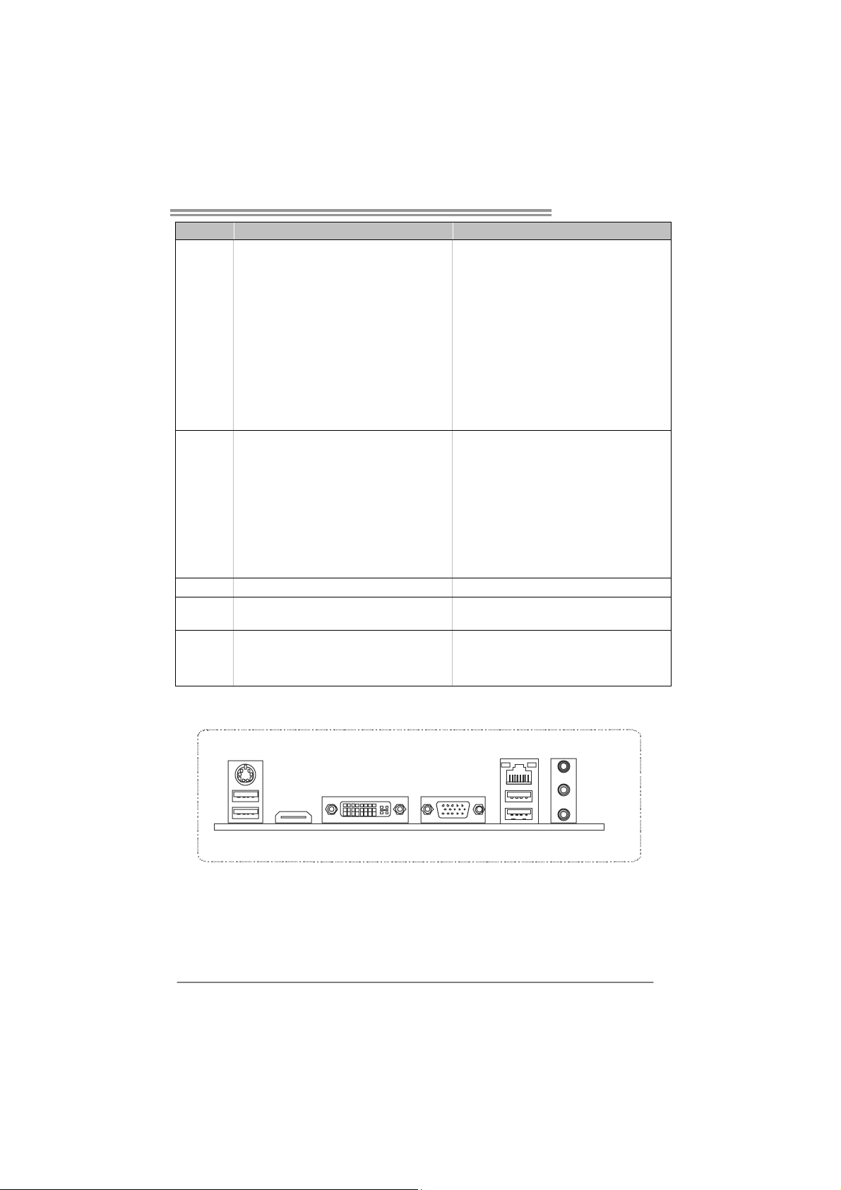
1.4 REAR PANEL CONNECTORS
PS/2
Keyboard / Mouse
USB2.0X2
HDMI
DV I-D
VGA
NOTE: USB3.0 ports are backward compatible with USB2.0/USB1.X devices.
LAN
USB3.0X2 ( A75MH)
USB2.0X2 ( A55MH)
Line In/
Surround
Line Out
Mic In 1/
Bass/ Center
3
Page 6
Motherboard Manual
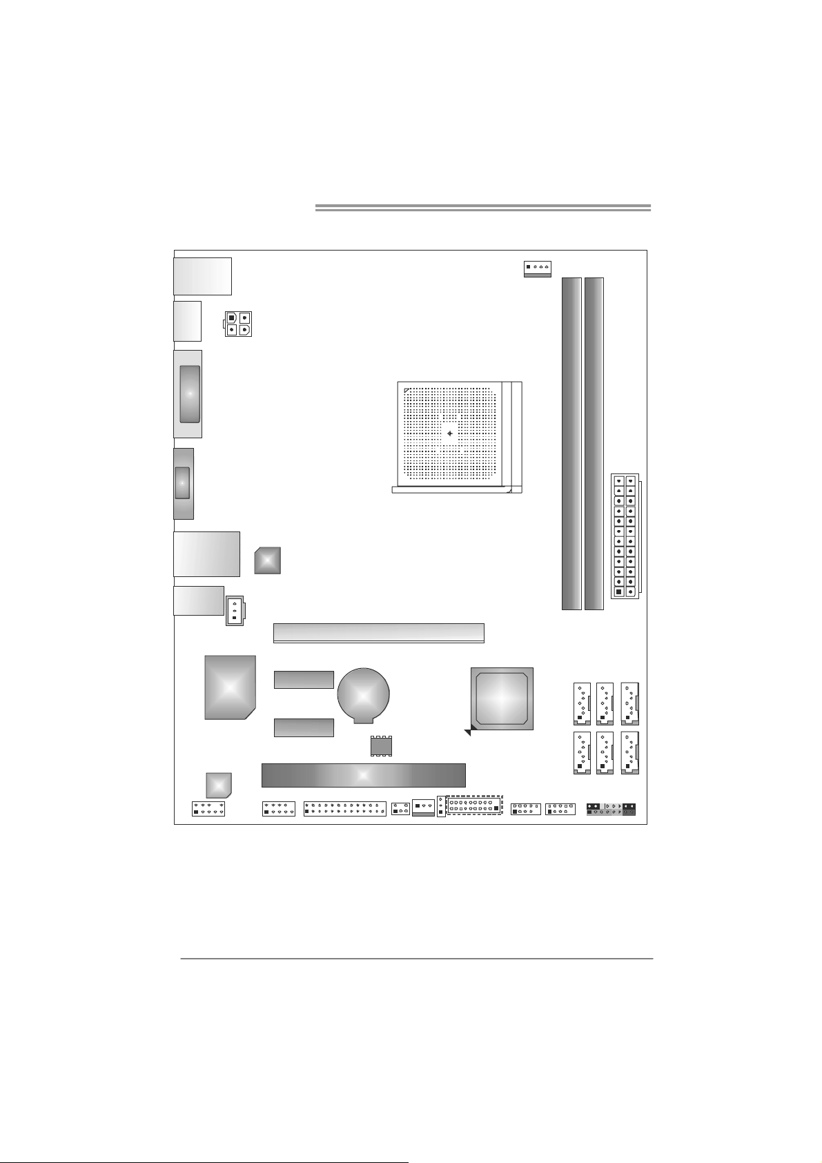
1.5 MOTHERBOARD LAYOUT
USB_KBMS1
HDMI1
DVI1
VGA1
RJ45USB1
AUDIO1
JSPD IFOUT1
ATX PW R2
LAN
PEX16_1
CPU_FAN1
DDR 3_A1
DDR 3_B1
ATX PW R1
4
Super
I/O
Code c
F_AUDIO1
Note: represents the 1■
J_COM1
PEX1_1
PEX1_2
BAT1
J_P RINT1
PCI1
BIOS
SYS_FAN1
CIR1
st
pin.
AMD
A75/
A55
(A75MH)
JFRONT_USB3_1 F_USB1
JCMOS1
F_USB2
SATA6SATA5SATA4
SATA1SATA2SATA3
PAN EL 1
Page 7
A75MH / A55MH
CHAPTER 2: HARDWARE INSTALLATION
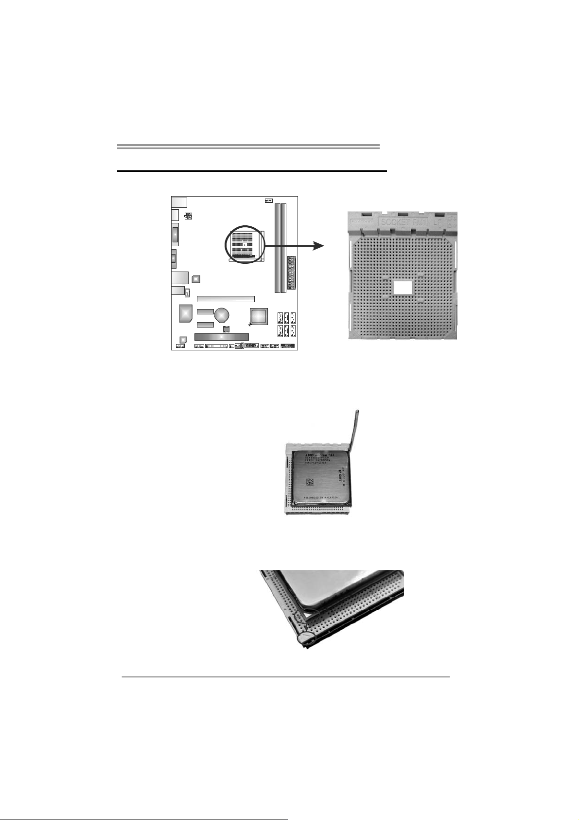
2.1 I
NSTALLING CENTRAL PROCESSING UNIT (CPU)
Step 1: Pull the lever toward direction A from the socket and then raise the
lever up to a 90-degree angle.
Step 2: Look for the white triangle on socket, and the gold triangle on
CPU should point towards this white triangle. The CPU will fit only
in the correct orientation.
5
Page 8
Motherboard Manual
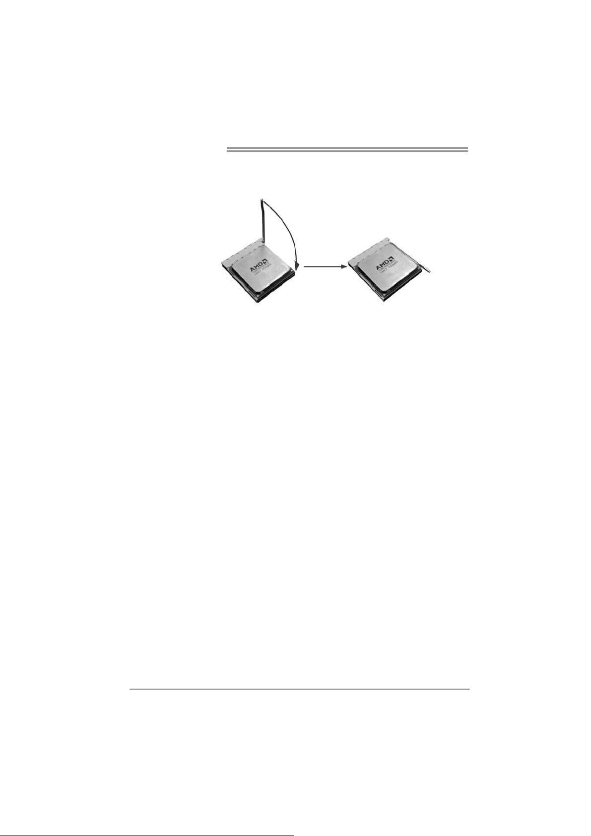
Step 3: Hold the CPU down firmly, and then close the lever toward direct
B to complete the installation.
Step 4: Put the CPU Fan on the CPU and buckle it. Connect the CPU
FAN power cable to the CPU_FAN1. This completes the
installation.
6
Page 9
A75MH / A55MH
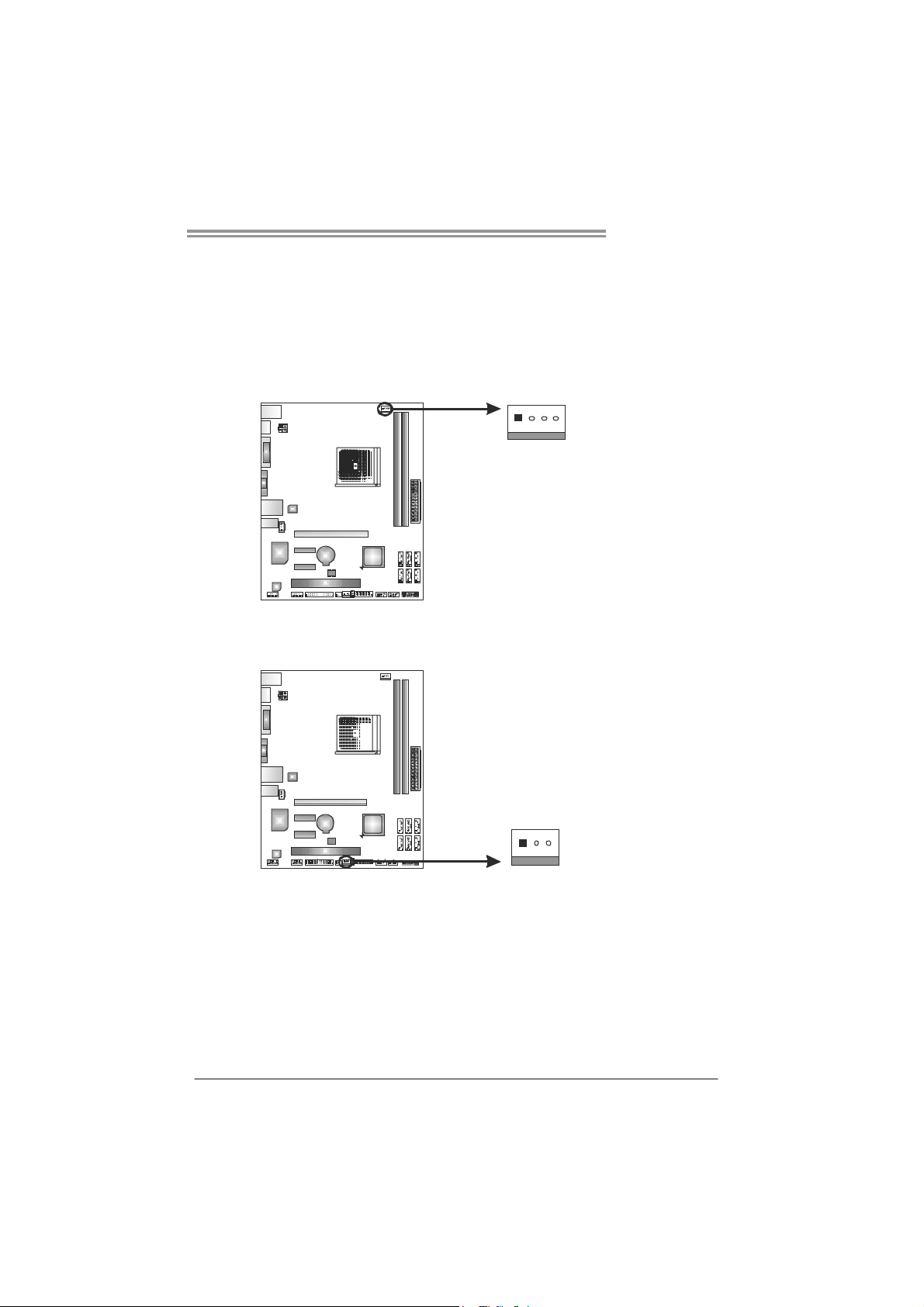
2.2 FAN HEADERS
These fan headers support cooling-fans built in the computer. The fan
cable and connector may be different according to the fan manufacturer.
Connect the fan cable to the connector while matching the black wire to
pin#1.
CPU_FAN1: CPU Fan Header
41
SYS_FAN1: System Fan Header
Pin
Assignment
1 Ground
2 +12V
3
FAN RPM r ate
sense
4 Smart Fan
Control (By Fan)
Pin
Assignment
1 Ground
2 +12V
3 FAN RPM rate
sense
13
Note:
CPU_FAN1 supports 4-pin head connector. SYS_FAN1 supports 3-pin head connector.
When connecting with wires onto connectors, please note that the red wire is the positive
and should be co nnected to pin#2, and the black wire is Ground and should be
connected to GND.
7
Page 10
Motherboard Manual
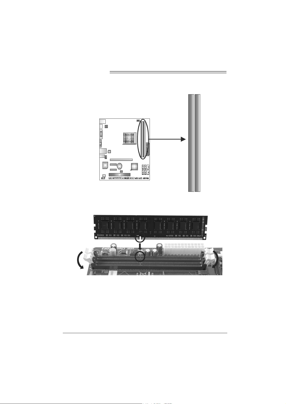
2.3 INSTALLING SYSTEM MEMORY
A. Memory Modules
D3_A1RD
1. Unlock a DIMM slot by pressing the retaining clips outward. Align a
DIMM on the slot such that the notch on the DIMM matches the
break on the Slot.
DDR B3_ 1
8
Page 11
A75MH / A55MH
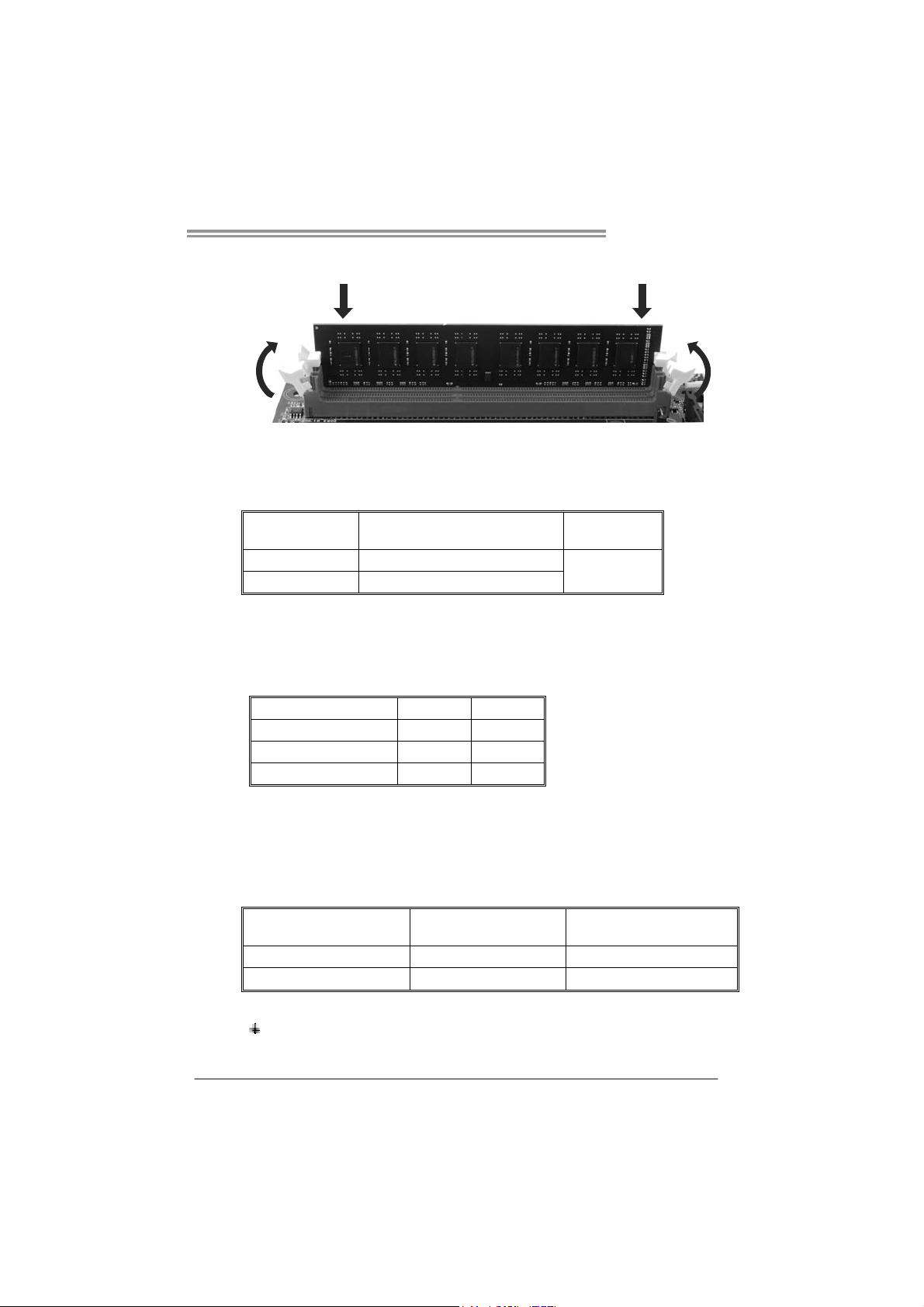
2. Insert the DIMM vertically and firmly into the slot until the retaining
chip snap back in place and the DIMM is properly seated.
Note:
If the DIMM does not go in smoothly, do not force it. Pull it all the way out
and try again.
B. Memory Capacity
DIMM Socket
Location
DDR3_A1 512MB/1GB/2GB/4GB/8GB
DDR3_B1 512MB/1GB/2GB/4GB/8GB
DDR3 Module
Total Mem ory
Size
Max is 16GB.
C. Dual Channel Memory installation
Please refer to the following requirements to activate Dual Channel function:
Install memory module of the same density in pairs, shown in the table
Dual Channel Status
Disabled X O
Disabled O X
Enabled O O
DDR3_A1
DDR3_B1
(O means memory installed, X means memory not installed.)
The DRAM bus width of the memory module must be the same (x8 or
x16)
D. DDR Speed Support
Please refer to the following table for DDR speed reference:
# of DIMM per Channel # of Ranks per DIMM
1 of 1 UDIMM xR DDR3-1866
1 of 2 UDIMMs xR DDR3-1600 / DDR3-1333
Max DDR Speed Grade
for 1.50V DIMM
Note:
xR: Single or double side memory moudule
9
Page 12
Motherboard Manual
4
1
2.4 CONNECTORS AND SLOTS
SATA1~SATA6: Serial ATA Connectors
A75MH/A55MH has a PCI to SATA Controller with 6 channels SATA interface.
A75MH satisfies the SATA 3.0 spec and with transfer rate of 6.0Gb/s; A55MH
satisfies the SATA 2.0 spec and with transfer rate of 3.0Gb/s.
SATA4 5 6
SA TA SATA SATA 2 1
ATXP W R2: ATX Power Source Connector
This connector will provide +12V to CPU power circuit.
SATA SATA
3
7
4
1
2
3
Pin
1 Ground
2 TX+
3 TX4 Ground
5 RX6 RX+
7 Ground
Pin
Assignment
1 +12V
2 +12V
3 Ground
4 Ground
Assignment
10
Page 13
A75MH / A55MH
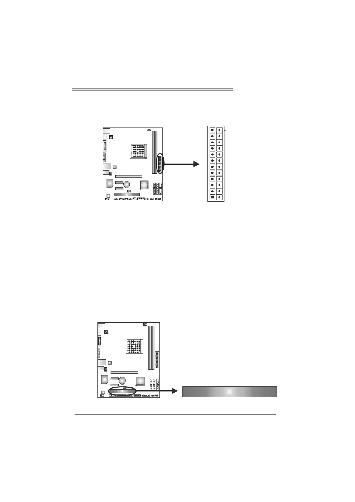
ATXP W R1: ATX Power Source Connector
This connector allows user to connect 24-pin power connector on the ATX
power supply.
12
1
Pin Assignment Pin Assignm ent
13 +3.3V 1 +3.3V
14 -12V 2 +3.3V
15 Ground 3 Ground
16 PS_ON 4 +5V
17 Ground 5 Ground
18 Ground 6 +5V
19 Ground 7 Ground
20 NC 8 PW_OK
21 +5V 9 Standby Voltage+5V
22 +5V 10 +12V
23 +5V 11 +12V
24 Ground 12 +3.3V
24
13
Note:
Before you power on the s ystem, please make sure that both ATXPWR1 and ATXPWR2
connectors have been plugged-in.
PCI1: Peripheral Component Inte rconnect Slot
This motherboard is equipped with 1 standard PCI slot. PCI stands for Peripheral
Component Interconnect, and it is a bus standard for expansion cards.
PCI1
11
Page 14
Motherboard Manual
PEX16_1: PCI-Express Gen2 x16 Slot
- PCI-Express 2.0 compliant.
- Maximum theoretical realized bandwidth of 8GB/s simultaneously per
direction, for an aggregate of 16GB/s totally.
- PCI-Express Gen2 supports a raw bit-rate of 5.0Gb/s on the data pins.
- 2X bandwidth over the PCI-Express 1.1 architecture.
PEX1_1/PEX1_2: PCI-Express Gen2 x1 Slots
- PCI-Express 2.0 compliant.
- Data transfer bandwidth up to 500MB/s per direction; 1GB/s in total.
- PCI-Express supports a raw bit-rate of 2.5Gb/s on the data pins.
PEX16_1
PEX1_1
12
PEX1_2
Page 15
A75MH / A55MH
CHAPTER 3: HEADERS & JUMPERS SETUP
3.1 H
OW TO SETUP JUMPERS
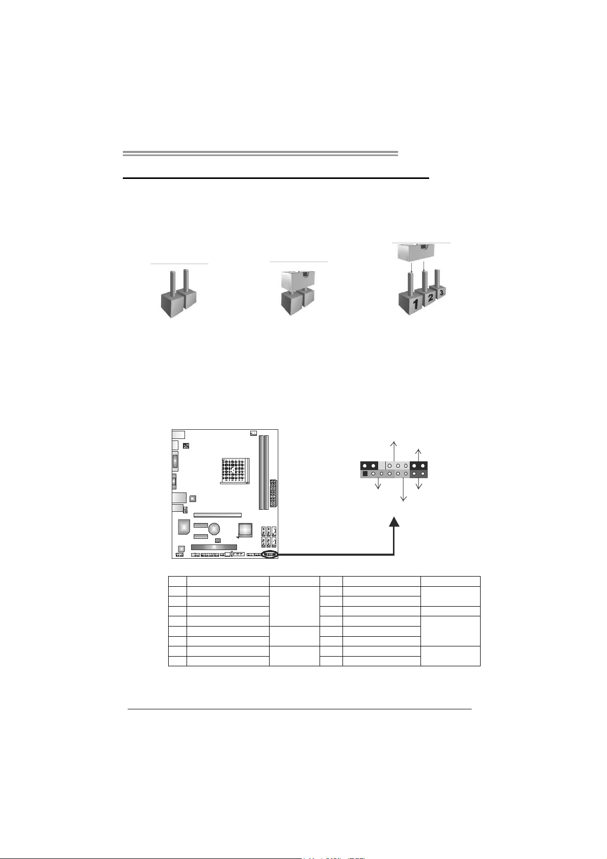
The illustration shows how to set up jumpers. When the jumper cap is
placed on pins, the jumper is “close”, if not, that means the jumper is
“open”.
Pin opened Pin closed Pin1-2 closed
3.2 DETAIL SETTINGS
PANEL1: Front Panel Header
This 16-pin connector includes Power-on, Reset, HDD LED, Power LED, and
speaker connection. It allows user to connect the PC case’s front panel switch
functions.
PWR_LED
On/Off
-
SPK
++
HLED
-
+
RST
9
1
16
8
Pin Assignment Function Pin Assignment Function
1 +5V
2 N/A 10 N/A
3 N/ A 11 N/ A N/A
4 Speaker 12 Power LED (+)
5 HDD LED (+)
6 HDD LED (-) 14 Power LED (-)
7 Ground
8 Reset control 16 Ground
Speaker
Connector
Hard drive
LED
Reset button
9 N/A
13 Power LED (+)
15 Power button
N/A
Power LED
Power-on button
13
Page 16
Motherboard Manual
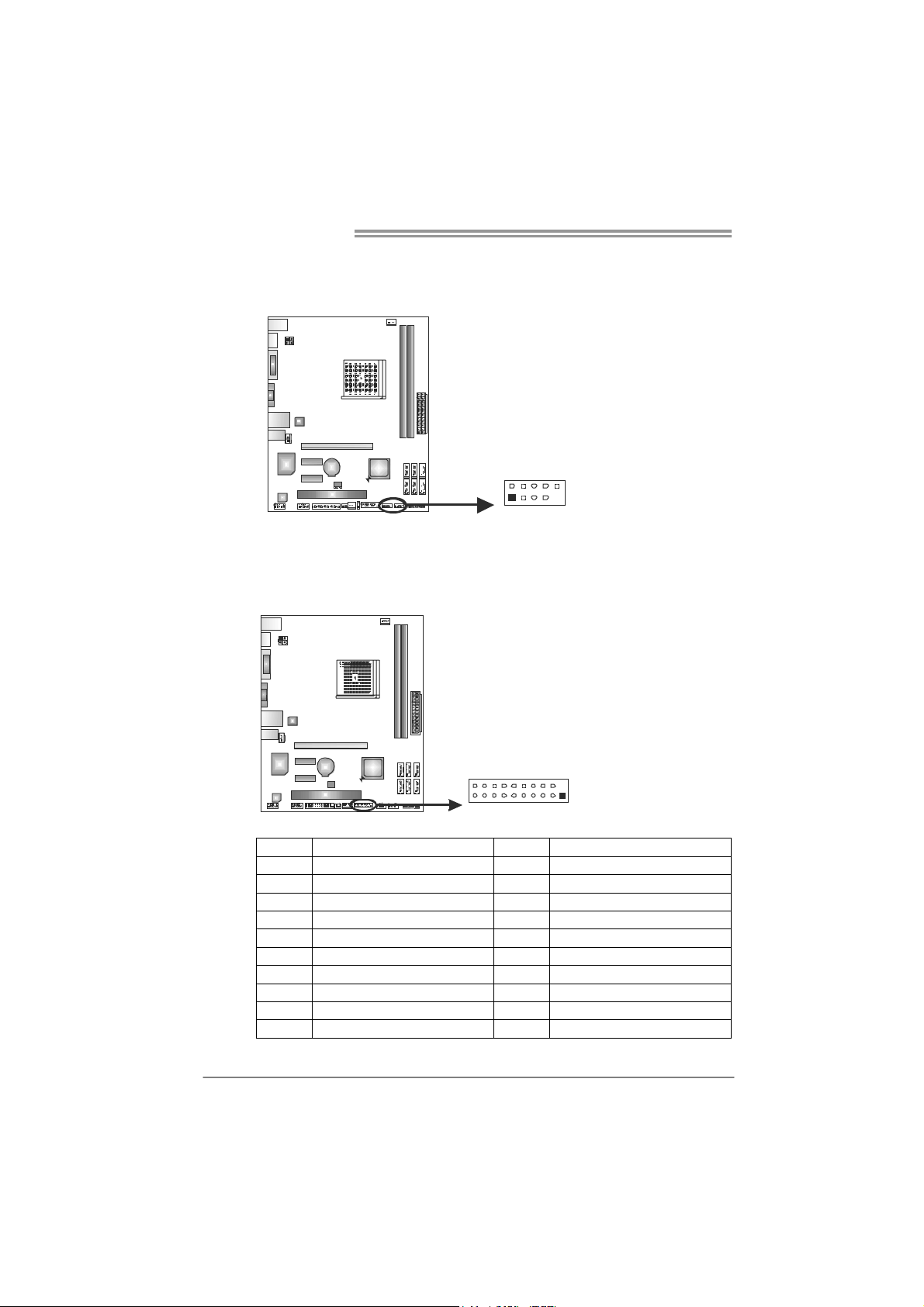
F_USB1/F_USB2: Headers for USB 2.0 Ports at Front Panel
This header allows user to connect additional USB cable on the PC front panel,
and also can be connected with internal USB devices, like USB card reader.
Pin
1 +5V (fused)
2 +5V (fused)
3 USB4 USB5 USB+
6 USB+
7 Ground
FUSB F_2 _USB1
102
91
8 Ground
9 NC
10 Key
JFRONT_USB3_1: Header for USB 3.0 Ports at Front Panel (A75MH)
This header allows user to connect additional USB cable on the PC front panel,
and also can be connected with internal USB devices, like USB card reader.
Assignment
14
2011
10
1
Pin Assignment Pin Assignment
1 VBUS0 11 D2+
2 SSRX1- 12 D2-
3 SSRX1+ 13 Ground
4 Ground 14 SSTX2+
5 SSTX1- 15 SSTX2-
6 SSTX1+ 16 Ground
7 Ground 17 SSRX2+
8 D1- 18 SSRX29 D1+ 19 VBUS1
10 ID 20 Key
Page 17

JSPDIFOUT1: Digital Audio-out Connector
This connector allows user to connect the PCI bracket SPDIF output header.
F_AUDIO1: Front Panel Audio Header
This header allows user to connect the front audio output cable with the PC front
panel. This header allows only HD audio front panel connector; AC’97 connector
is not acceptable.
3
1
210
A75MH / A55MH
Pin
Assignment
1 +5V
2 SPDIF_OUT
3 Ground
Pin Assignment
1 Mic Left in
2 Ground
3 Mic Right in
4 GPIO
5 Right line in
6 Jack Sense
7 Front Sense
8 Key
9 Left line in
10 Jack Sense
19
15
Page 18

Motherboard Manual
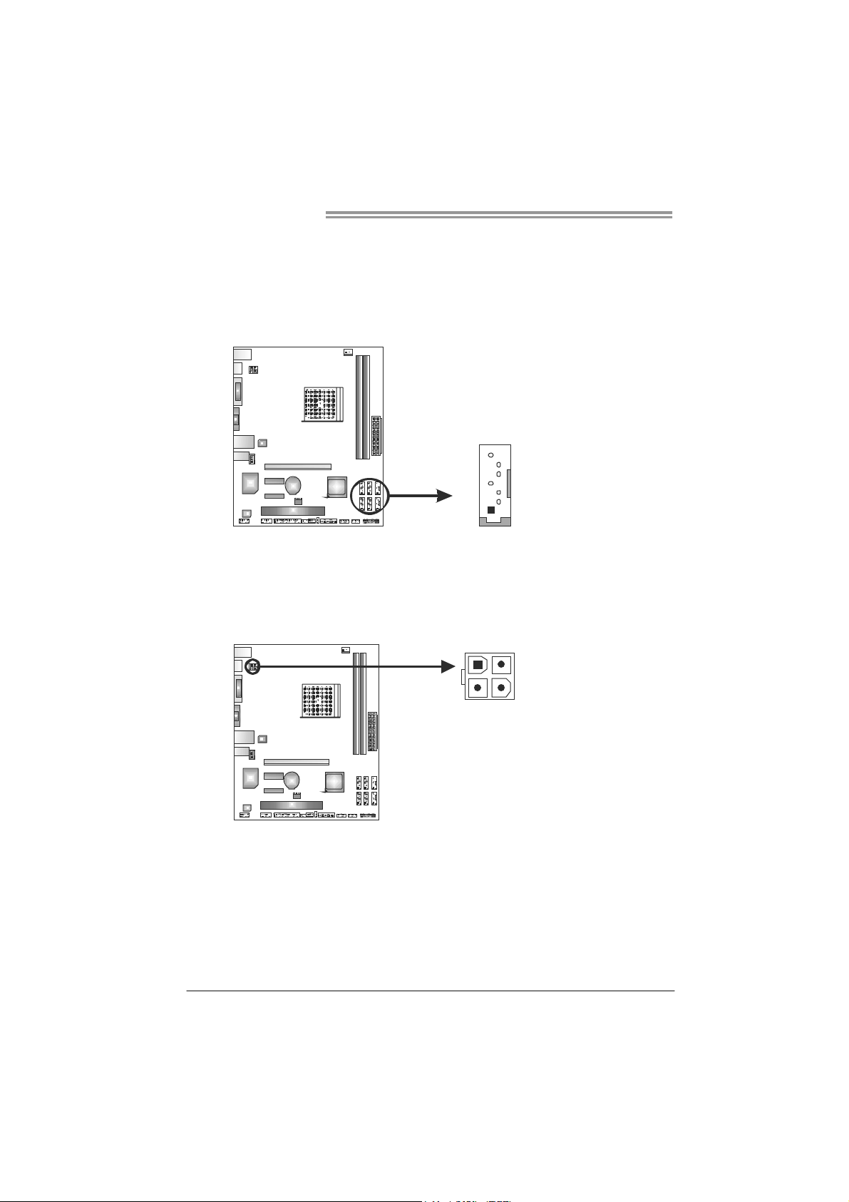
JCMOS1: Clear CMOS Header
Placing the jumper on pin2-3, it allows user to restore the BIOS safe setting and
the CMOS data. Please carefully follow the procedures to avoid damaging the
motherboard.
※ Clear CMOS Procedures:
1. Remove AC power line.
2. Set the jumper to “Pin 2-3 close”.
3. Wait for five seconds.
4. Set the jumper to “Pin 1-2 close”.
5. Power on the AC.
6. Load Optimal Defaults and save settings in CMOS.
3
1
Pin 1-2 Close:
Normal Operation (default).
3
1
3
1
Pin 2-3 Close:
Clear CMOS data.
J_COM1: Serial Port Connector
The motherboard has a Serial Port Connector for connecting RS-232 Port.
16
Pin
210
19
Assignment
1 Carrier detect
2 Received data
3 Transmitted data
4 Data terminal ready
5 Signal ground
6 Data set ready
7 Request to send
8 Clear to send
9 Ring indicator
10 NC
Page 19

J_PRINT1: Printer Port Connector
This header allows you to connector printer on the PC.
A75MH / A55MH
2
26
125
Pin Assignment Pin Assignment
1 -Strobe 14 Ground
2 -ALF 15 Data 6
3 Data 0 16 Ground
4 -Error 17 Data 7
5 Data 1 18 Ground
6 -Init 19 -ACK
7 Data 2 20 Ground
8 -Scltin 21 Busy
9 Data 3 22 Ground
10 Ground 23 PE
11 Data 4 24 Ground
12 Ground 25 SCLT
13 Data 5 26 Key
CIR1: Consumer IR Connector
This header is for infrared remote control and communication.
6
125
Pin Assignment
1 IrDA serial input
2 Ground
3 Ground
4 Key
5 IrDA serial output
6 IR Power
17
Page 20

Motherboard Manual
CHAPTER 4: AMD DUAL GRAPHICS TECHNOLOGY
4.1 AMD
DUAL GRAPHICS TECHNOLOGY INTRODUCTION
When user adds a PCIE display adapter, it can be integrated with IGD
to show better performance. To make the two video devices work
simultaneously and normally, please refer to the following setting.
4.2 AMD DUAL GRAPHICS REQUIREMENT
Operating System: Windows Vista / Windows 7
Supported DUAL Graphics Combinations:
APU
GFX
HD 6670 Attach Only (No DG)
HD 6570 Attach Only (No DG)
HD 6450
HD 6350
Note:
“Attach Only (No DG)” indicates supported discrete graphics attachment
without Dual Graphics.
E-Series CPU do not support Dual Graphics.
Notice:
Single Channel or unbalanced memory does not support Dual Graphic function.
Please use at least DDR3-1333 4G (2G+2G).
A4-Series
HD 6410D
A6-Series
HD 6530D
Y Y Y
Y
Attach Only (No DG)
A8-Series”
HD 6550D
Y Y
Y Y
Attach Only (No DG)
18
NOTE
The information described above in this manual is for your reference only and
the actual information and settings on board may be different from this manual.
For further AMD Dual Graphics information, please visit the following website:
http://www.amd.com
Page 21

A75MH / A55MH
4.3 AMD DUAL GRAPHICS SETUP
Step 1: Insert Dual Graphics-Ready graphics card into PEX16_1 slot.
Step 2: Set the BIOS setting as follows:
[Chipset]→[North Bridge]→[Surround View]→[Enabled]
Step 3: Install Driver CD Chipset Driver, and reboot the system. Activate AMD
VISION Engine Control Center to make sure CrossFire has been
enabled.
19
Page 22

Motherboard Manual
CHAPTER 5: RAID FUNCTIONS
5.1 O
Supports Windows XP, Windows Vista, and Windows 7.
PERATING SYSTEM
5.2 RAID ARRAYS
RAID supports the following types of RAID arrays:
RAID 0: RAID 0 defines a disk striping scheme that improves disk read and write times for
many applications.
RAID 1: RAID 1 defines techniques for mirroring data.
RAID 10: RAID 10 combines the techniques used in RAID 0 and RAID 1.
5.3 HOW RAID WORKS
RAID 0:
The controller “stripes” data across multiple drives in a RAID 0 array system. It breaks
up a large f ile in to sm al ler blo ck s a nd pe rf or ms dis k r ea ds a nd w rit es ac ro ss mu ltip le
drives in parallel. The size of each block is determined by the stripe size parameter,
which you set during the creation of the RAID set based on the system environment. This
technique reduces overall disk access time and offers high bandwidth.
Features and Benefits
Drives: Minimum 2, and maximum is up to 6 or 8. Depending on the
platform.
Uses: Intended for non-critical data requiring high data throughput, or any
environment that does not require fault tolerance.
Benefits: provides increased data throughput, especially for large files. No
capacity loss penalty for parity.
Drawbacks: Does not deliver any fault tolerance. If any drive in the array
fails, all data is lost.
Fault Tolerance: No.
20
Block 1
Blo ck 3
Blo ck 5
Block 2
Blo ck 4
Blo ck 6
Page 23

A75MH / A55MH
RAID 1:
Every read and write is actually carried out in parallel across 2 disk drives in a RAID 1
array system. The mirrored (backup) copy of the data can reside on the same disk or on a
second redundant drive in the array. RAID 1 provides a hot-standby copy of data if the
active volume or drive is corrupted or becomes unavailable because of a hardware failure.
RAID techniques can be applied for high-availability solutions, or as a form of automatic
backup that eliminates tedious manual backups to more expensive and less reliable
media.
Features and Benefits
Drives: Minimum 2, and maximum is 2.
Uses: RAID 1 is ideal for small databases or any other application that
requires fault tolerance and minimal capacity.
Benefits: Provides 100% data redundancy. Should one drive fail, the
controller switches to the other drive.
Drawbacks: Requires 2 drives for the storage space of one drive.
Performance is impaired during drive rebuilds.
Fault Tolerance: Yes.
Block 1
Block 2
Block 3
Block 1
Block 2
Block 3
21
Page 24

Motherboard Manual
RAID 10:
RAID 1 drives can be stripped using RAID 0 techniques. Resulting in a RAID 10
solution for improved resiliency, performance and rebuild performance.
Features and Benefits
Drives: Minimum 4, and maximum is 6 or 8, depending on the platform.
Benefits: Optimizes for both fault tolerance and performance, allowing for
automatic redundancy. May be simultaneously used with other RAID levels
in an array, and allows for spare disks.
Drawbacks: Requires twice the available disk space for data redundancy,
the same as RAID level 1.
Fault Tolerance: Yes.
22
Block 1
Block 3
Block 5
Block 1
Block 3
Block 5
Block 2
Block 4
Block 6
Block 2
Block 4
Block 6
Page 25

CHAPTER 6: USEFUL HELP
A75MH / A55MH
6.1 D
RIVER INSTALLATION NOTE
After you installed your operating system, please insert the Fully Setup
Driver CD into your optical drive and install the driver for better system
performance.
You will see the following window after you insert the CD
The setup guide will auto detect your motherboard and operating system.
Note:
If this window didn’t show up after you insert the Driver CD, please use file browser to
locate and execute the file SETUP.EXE under your optical drive.
A. Driver Installation
To install the driver, please click on the Driver icon. The setup guide will
list the compatible driver for your motherboard and operating system.
Click on each device driver to launch the installation program.
B. Software Installation
To install the software, please click on the Software icon. The setup guide
will list the software available for your system, click on each software title
to launch the installation program.
C. Manual
Aside from the paperback manual, we also provide manual in the Driver
CD. Click on the Manual icon to browse for available manual.
Note:
Yo u will need Acrobat Reader to open the manual file. Please download the latest version
of Acrobat Reader software from
http://www.adobe.com/products/acrobat/readstep2.html
23
Page 26

Motherboard Manual
e
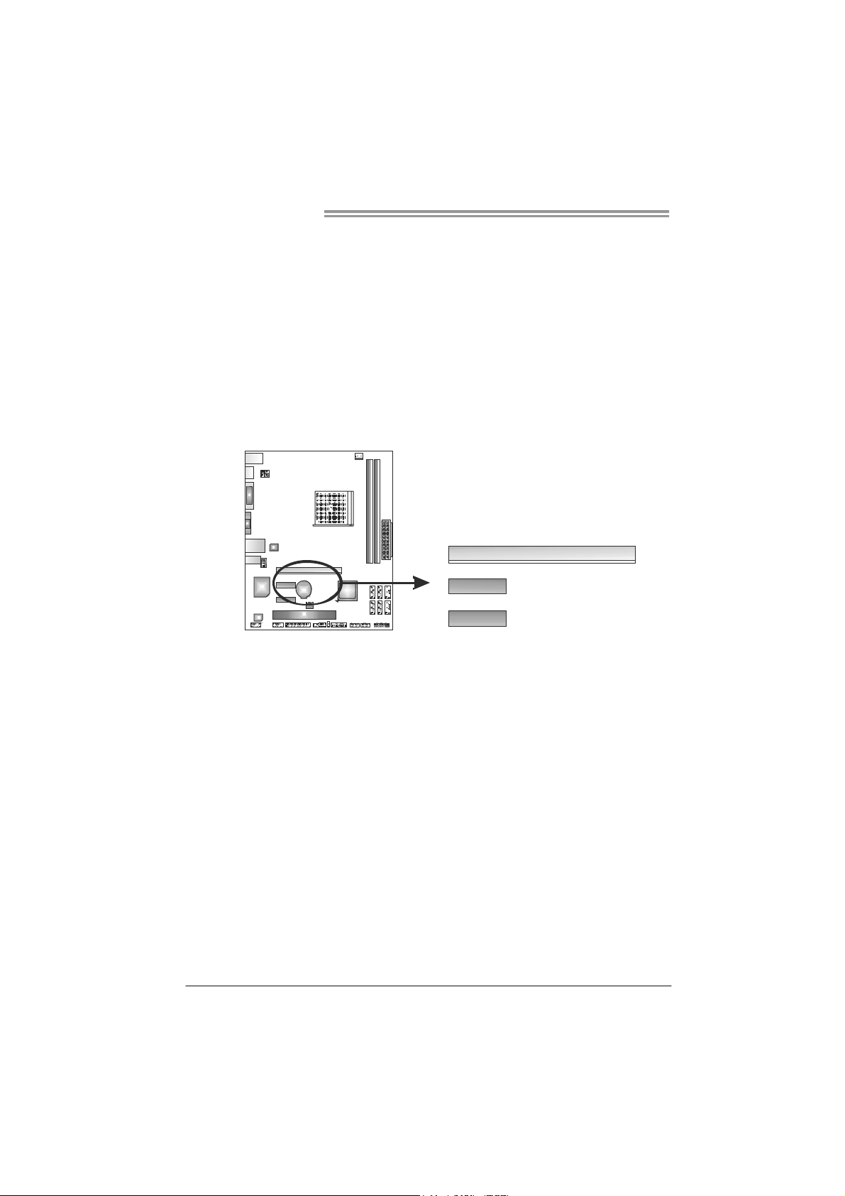
6.2 SOFTWARE
Installing Software
1. Insert the Setup CD to the optical drive. The drivers installation program
would appear if the Autorun function has been enabled.
2. Select Software Installation, and then click on the respective software
title.
3. Follow the on-screen instructions to complete the installation.
Launching Software
After the installation process, you will see the software icon “eHOT Line” /
“BIOS Update” appears on the desktop. Double-click the icon to launch the
utility.
eHot-Line (Optional)
eHot-Line is a convenient utility that helps you to contact with our
Tech-Support system. This utility will collect the system information which is
useful for analyzing the problem you may have encountered, and then send
these information to our tech-support department to help you fix the problem.
Before you use this uti lity, please set Outlook E xpress as your default e-mail client applicatio n program.
re pr esen ts i mpor ta nt
*
information that you
must provide. Without
this information, y ou may
not be able to send out
the mail.
This block will show
the information which
would be collected in
the mail.
Describe condition
*
of your system.
Select your area or
*
the area close to you.
Provide the e-mail
address that you would
like to send the copy to.
Pr ovid e the name of
*
the memory module
manufacturer.
Provide the name of
th e powe r su ppl y
manufacturer and the
model no.
Se nd th e mai l out .
Sav e the se in forma tion to a .txt fil
Exit this dialog.
24
Page 27

A75MH / A55MH
After filling up this informatio n, click “Send”
to send the mail out. A warning dialog would
appear asking for your confirmation; click
“Send” to confirm or “Do Not Send” to cancel.
If you want to save this information to a .txt file, click “Save As…” and then you
will see a saving dialog appears asking you to enter file name.
Enter the file name and then click
“Save”. Your system information
will be saved to a .txt file.
Open the saved .txt file, you will see
your system information including
motherboard/BIOS/CPU/video/
device/OS information. This
information is also concluded in the
sent mail.
We will not share custo mer ’s data with any other third parties,
so please feel free to provide your system information while using
eHot-Line service.
If you are not using Outlook Express as your default e-mail client
application, you may need to save the system information to a .txt file
and send the file to our tech support with other e-mail application.
Go to the following web
http://www.biostar.com.tw/app/en-us/about/contact.php for getting
our contact information.
25
Page 28

Motherboard Manual
BIOS Update
BIOS Update is a convenient utility which allows you to update your
motherboard BIOS under Windows system.
AWARD BIOS AMI BIOS
Clear CMOS function
(Only for AWARD BIOS)
Show current BIOS information
Save cur rent BIOS
to a .bin file
Update BIOS
with a BIOS file
<Backup BIOS>
Once click on this button, the saving
dialog will show. Choose the
position to save file and enter file
name. (We recommend that the file
name should be English/number
and no longer than 7 characters.)
Then click Save.
26
Page 29

A75MH / A55MH
<Update BIOS>
Before doing this, please download the proper BIOS file from the website.
For AWARD BIOS, update BIOS procedure
should be run with Clear CMOS function, so
please check on Clear CMOS first.
Then click Update BIOS button, a
dialog will show for asking you backup
current BIOS. Click Yes for BIOS
backup and refer to the Backup BIOS
procedure; or click No to skip this
procedure.
After the BIOS Backup procedure, the
open dialog will show for requesting the
BIOS file which is going to be updated.
Please choose the proper BIOS file for
updating, then click on Open.
The utility will update BIOS with the
proper BIOS file, and this process may
take minutes. Please do not open any
other applications during this process.
After the BIOS Update process, click on
OK to restart the system.
While the system boots up and the full screen logo shows, press <Delete>
key to enter BIOS setup.
In the BIOS setup, use the Load Optimized Defaults function and then Save and
Exit Setup to exit BIOS setup. BIOS Update is completed.
All the information and content above about the software are subject to be changed
without notice. For better performance, the software is being continuously updated.
The information and pictures described above are for your reference only. The actual
information and settings on board may be slightly different from this manual.
27
Page 30

Motherboard Manual
6.3 EXTRA INFORMATION
CPU Overheated
If the system shutdown automatically after power on system for
seconds, that means the CPU protection function has been activated.
When the CPU is over heated, the motherboard will shutdow n
automatically to avoid a damage of the CPU, and the system may not
power on again.
In this case, please double check:
1. The CPU cooler surface is placed evenly with the CPU surface.
2. CPU fan is rotated normally.
3. CPU fan speed is fulfilling with the CPU speed.
After confirmed, please follow steps below to relief the CPU protection
function.
1. Remove the power cord from power supply for seconds.
2. Wait for seconds.
3. Plug in the power cord and boot up the system.
Or you can:
1. Clear the CMOS data.
(See “Close CMOS Header: JCMOS1” section)
2. Wait for seconds.
3. Power on the system again.
28
Page 31

BIO-Flasher
A75MH / A55MH
BIO-Flasher is a BIOS flashing utility providing you an easy and simple way to
update your BIOS via USB pen drive or floppy disk.
The BIO-Flasher is built in the BIOS chip. To enter the utility, press <F12>
during the Power-On Self Tests (POST) procedure while booting up.
Updating BIOS with BIO-Flasher
1. Go to the website to download the latest BIOS file for the motherboard.
2. Then, save the BIOS file into a USB pen drive or a floppy disk.
3. Insert the USB pen drive or the floppy disk that contains the BIOS file to the
USB port or the floppy disk drive.
4. Power on or reset the computer and then
press <F12> during the POST process.
A select dialog as the picture on the right
appears.
Select the device contains the BIOS file and
press <Enter> to enter the utility.
5. The utility will show the BIOS
files and their respective
information. Select the proper
BIOS file and press <Enter>
then <Y> to perform the BIOS
update process.
6. After the update process, the utility will ask you to reboot the system.
Press <Y> to proceed. BIOS update completes.
z This utility only allows storage device with FAT32/16 format and single
partition.
z Shutting down or resetting the system while updating the BIOS will lead to
system boot failure.
29
Page 32

Motherboard Manual
6.4 AMI BIOS BEEP CODE
Boot Block Beep Codes
Number of Beeps De scription
1 No media present. (Insert diskette in floppy drive A:)
2
3 Insert next diskette if multiple diskettes are used for recovery
4 Flash Programming successful
5 File read error
7 No Flash EPROM detected
10 Flash Erase error
11 Flash Program error
12 “AMIBOOT.ROM” file size error
13
POST BIOS Beep Codes
Number of Beeps De scription
1 Memory refresh timer error
3 Base memory read/write test error
6 Keyboard controller BAT command failed
7 General exception error (processor exception interrupt error)
8 Display memory error (system video adapter)
“AMIBOOT.ROM” file not found in root directory of diskette in
A:
BIOS ROM image mismatch (file layout does not match
image present in flash device)
Troubleshooting POST BIOS Beep Codes
Number of Beeps Troubleshooting Action
1, 3 Reseat the memory, or replace with known good modules.
Fatal error indicating a serious problem with the system.
Consult your system manufacturer. Before declaring the
motherboard beyond all hope, eliminate the possibility of
interference by a malfunctioning add-in card. Remove all
expansion cards except the video adapter.
z If beep codes are generated when all other expansion
6, 7
8
30
cards are absent, consult your system manufacturer’s
technical support.
z If beep codes are not generated when all other expansion
cards are absent, one of the add-in cards is causing the
malfunction. Insert the cards back into the system one at a
time until the problem happens again. This will reveal the
malfunctioning card.
If the system video adapter is an add-in card, replace or
reseat the
video adapter. If the video adapter is an integrated part of the
system board, the board may be faulty.
Page 33

6.5 TROUBLESHOOTING
Probable Solution
1. There is no power in the system.
Power LED does not shine; the
fan of the power supply does not
work
2. Indicator light on keyboard does
not shine.
System is inoperative. Keyboard lights
are on, power indicator lights are lit,
and hard drives are running.
System does not boot from a hard disk
drive, but can be booted from optical
drive.
System only boots from an optical
drive. Hard disks can be read,
applications can be used, but system
fails to boot from a hard disk.
Screen message shows “Invalid
Configuration” or “CMOS Failure.”
System cannot boot after user installs a
second hard drive.
A75MH / A55MH
1. Make sure power cable is
securely plugged in.
2. Replace cable.
3. Contact technical support.
Using even pressure on both ends of
the DIMM, press down firmly until the
module snaps into place.
1. Check cable running from disk to
disk controller board. Make sure
both ends are securely plugged
in; check the drive type in the
standard CMOS setup.
2. Backing up the hard drive is
extremely important. All hard
disks are capable of breaking
down at any time.
1. Back up data and applications
files.
2. Reformat the hard drive.
Re-install applications and data
using backup disks.
Review system’s equipment. Make sure
correct information is in setup.
1. Set master/slave jumpers
correctly.
2. Run SETUP program and select
correct drive types. Call the drive
manufacturers for compatibility
with other drives.
31
Page 34

Motherboard Manual
APPENDIX: SPEC IN OTHER LANGUAGES
G
ERMAN
A75MH A55M H
CPU
Chipsatz
Super E/A
Arbeitsspeich
er
SATA3/
SATA2
LAN
HD
Audio-Unters
tützung
USB3.0
Steckplätze
Sockel FM1
AMD A-Series / E2-Series Prozessoren
Die A MD 64- Architektur unt erstützt ein e 32- Bit-
und 64-Bit-Datenverarbeitung
AMD A75 AMD A55
ITE 8728
Biet et die häufig verwendeten alten Sup er
E/A-Funktionen.
Low Pin Count-Schnittstelle
Umgebungskontrolle,
Hardware-Überwachung
"Smart Guardian"-Funktion von ITE
DDR3 DIMM-Steckplätze x 2
Max. 16GB Arbeitsspeicher
Jeder DIMM unterstützt
512MB/1GB/2GB/4GB/8GB DDR3.
Dual-Kanal DDR3 Speichermodul
Unterstützt DDR3 800/1066/1333/1600/1866
registrierte DIMMs. ECC DIMMs werden nicht
unterstützt.
Integrierter Serial ATA-Controller
Datentransferrate b is zu 6 Gb/s
Konform mit der SATA-Spezifikation Version 3.0
Realtek RTL 8111E/8111F
10 / 100 / 1000 Mb/s Auto-Negotiation
Halb-/ Vollduplex-Funktion
VT1708B/ALC662
5.1-Kanal-Audioausgabe
Unterstützt High-Definition Audio
A75 N/A
PCI Express Gen2 x16 Steckplatz x1 PCI Express Gen2 x16 Steckplatz x1
PCI Express Gen2 x1 Steckplatz x2 PCI Express Gen2 x1 Steckplatz x2
PCI-St eckp latz x 1 PCI-St eckp latz x 1
Sockel FM1
AMD A-Series / E2-Series Prozessoren
Die AMD 64-Architektur unterstützt eine 32-Bit-
und 64-Bit-Datenverarbeitung
ITE 8728
Biet et die häufig verwendeten alten Sup er
E/A-Funktionen.
Low Pin Count-Schnittstelle
Umgebungskontrolle,
Hardware-Überwachung
"Smart Guardian"-Funktion von ITE
DDR3 DIMM-Steckplätze x 2
Max. 16GB Arbeitsspeicher
Jeder DIMM unterstützt
512MB/1GB/2GB/4GB/8GB DDR3.
Dual-Kanal DDR3 Speichermodul
Unterstützt DDR3 800/1066/1333/1600/1866
registrierte DIMMs. ECC DIMMs werden nicht
unterstützt.
Integrierter Serial ATA-Controller
Datentransferrate b is zu 3 Gb/s
Ko nform mit der SATA -S pezif ikation Version 2.0
Realtek RTL 8111E/8111F
10 / 100 / 1000 Mb/s Auto-Negotiation
Halb-/ Vollduplex-Funktion
VT1708B/ALC662
5.1-Kanal-Audioausgabe
Unterstützt High-Definition Audio
32
Page 35

A75MH A55M H
SATA3-Anschluss x6 SATA2-Anschluss x6
Fronttafelanschluss x1 Fronttafelanschluss x1
Front-Audioanschluss x1 Front-Audioanschluss x1
S/PDIF- Ausgangsanschluss x1 S/PDIF- Ausgangsanschluss x1
CPU-Lüfter-Sockel x1 CPU-Lüfter-Sockel x1
System-Lüfter-Sockel x1 System-Lüfter-Sockel x1
Onboard-Ans
chluss
Rückseiten-E
/A
Platinengröß
e
Sonderfunkti
onen
OS-Unterstü
tzung
"CMOS lös chen "-Sockel x1 "CMOS löschen "-S ockel x1
USB 2.0-Anschluss x2 USB 2.0-Anschluss x2
USB 3.0-Anschluss x1 N/A
Stromanschluss (24-polig) x1 Stromanschluss (24-polig) x1
St romans ch luss (4 -po lig ) x1 Stromans ch luss (4-po lig) x1
Verbraucher-IR Anschluss x1 Verbraucher-IR Anschluss x1
Druckeranschluss Anschluss x1 Druckeranschluss Anschluss x1
Serieller Anschluss x1 Serieller Anschluss x1
PS/2-Tastatur / Maus x1
HDMI-Anschluss x1
VGA-Anschluss x1
DVI-D-Anschluss x1
LAN-Anschluss x1
USB 2.0-Anschluss x2
USB 3.0-Anschluss x2
Audioanschluss x3
200 mm (B) X 244 mm (L) 200 mm (B) X 244 mm (L)
Unterstützt RAID 0 / 1 / 10 Unterstützt RAID 0 / 1 / 10
Windows XP / Vista / 7
Biostar behält sich das Recht vor, ohne
Ankündigung die Unterstützung für ein
Betriebssystem hinzuzufügen oder zu
entfernen.
PS/2-Tastatur / Maus x1
HDMI-Anschluss x1
VGA-Anschluss x1
DVI-D-Anschluss x1
LAN-Anschluss x1
USB 2.0-Anschluss x4
Audioanschluss x3
Windows XP / Vista / 7
Biostar behält sich das Recht vor, ohne
Ankündigung die Unterstützung für ein
Betriebssystem hinzuzufügen oder zu
entfernen.
A75MH / A55MH
33
Page 36

Motherboard Manual
FRENCH
A75MH A55MH
Socket FM1
UC
Chipset
Super E/S
Mémoire
principale
SATA3/
SATA2
LAN
Prise en
charg e
aud io HD
USB3.0 A75 N/A
Fentes
Processeurs AMD A-Series / E2-Series
L'architecture AMD 64 permet le calcul 32 et 64
bits
AMD A75 AMD A55
ITE 8728
Fournit la fonctionnalité de Super E/S
patrimoniales la plus utilisée.
Int erface à faib le co mpt e d e b roches
Initiatives de contrôle environnementales
Mon iteur d e mat ériel
Fonction "Gardien intelligent" de l'ITE
Fentes DDR3 DIMM x 2
Capac ité mémo ir e max i mal e de 16Go
Chaque DIMM prend en charge des DDR3 de
256 Mo/512 Mo et 1Go/2Go/4Go/8Go
Module de mémoire DDR3 à mode à doub le voie
Prend en charge la DDR3
800/1066/1333/1600/1866
Les DIMM à registres et DIMM avec code
correcteurs d'err eurs ne s ont pas prises en
charg e
Contrô leur Serial ATA int égr é
Taux de transfert jusqu'à 6 Go/s
Co nforme à la s pécificat ion SATA Vers ion 3.0
Realtek RTL 8111E/8111F
10 / 100 / 1000 Mb /s négociation auto matique
Half / Full duplex capability
VT1708B/ALC662
Sortie audio à 5.1 vo ies
Prise en charg e de l'audio haut e défin ition
Fente PCI Express Gen2 x16 x1 Fente PCI Express Gen2 x16 x1
Fente PCI Express Gen2 x1 x2 Fente PCI Express Gen2 x1 x2
Fente PCI x1 Fente PCI x1
Socket FM1
Processeurs AMD A-Series / E2-Series
L'architecture AMD 64 permet le calcul 32 et 64
bits
ITE 8728
Fournit la fonctionnalité de Super E/S
patrimoniales la plus utilisée.
Int erface à faib le co mpt e d e b roches
Initiatives de contrôle environnementales
Mon iteur d e mat ériel
Fonction "Gardien intelligent" de l'ITE
Fentes DDR3 DIMM x 2
Capac ité mémo ir e max i mal e de 16Go
Chaque DIMM prend en charge des DDR3 de
256 Mo/512 Mo et 1Go/2Go/4Go/8Go
Module de mémoire DDR3 à mode à doub le voie
Prend en charge la DDR3
800/1066/1333/1600/1866
Les DIMM à registres et DIMM avec code
correcteurs d'err eurs ne s ont pas prises en
charg e
Contrô leur Serial ATA int égr é
Taux de transfert jusqu'à 3 Go/s
Co nforme à la s pécificat ion SATA Vers ion 2.0
Realtek RTL 8111E/8111F
10 / 100 / 1000 Mb /s négociation auto matique
Half / Full duplex capability
VT1708B/ALC662
Sortie audio à 5.1 vo ies
Prise en charg e de l'audio haut e défin ition
34
Page 37

A75MH A55MH
Connecteur SATA3 x6 Connecteur SATA2 x6
Connecteur du panneau avant x1 Connecteur du panneau avant x1
Connecteur Audio du panneau avant x1 Connecteur Audio du panneau avant x1
Connecteur de sortie S/PDIF x1 Connecteur de sortie S/PDIF x1
Embase de ventilateur UC x1 Embase de ventilateur UC x1
Embase de ventilateur système x1 Embase de ventilateur système x1
Embase d'effacement CMOS x1 Embase d'effacement CMOS x1
Connecteur
embarqué
E/S du
panneau
arrière
Dimension
s de la
cart e
Fonctionnal
ité s
spéciales
Support SE
Connecteur USB 2.0 x2 Connecteur USB 2.0 x2
Connecteur USB 3.0 x1 N/A
Connecteur d' alimentation x1
(24 broches)
Connecteur d' alimentation x1
(4 broches)
Connecteur de IR du consommateur
x1
Connecteur de Port d'imprimante x1 Connecteur de Port d'imprimante x1
Connecteur de Port série x1 Connecteur de Port série x1
Clavier / Souris PS/2 x1
Port HDMI x1
Port VGA x1
Port DVI-D x1
Port LAN x1
Port USB 2.0 x2
Port USB 3.0 x2
Fiche aud io x3
200 mm (l) X 244 mm (H) 200 mm (l) X 244 mm (H)
Prise en charg e RAID 0 / 1 / 1 0 Prise en charge RAID 0 / 1 / 10
Windows XP / Vista / 7
Biostar se réserve le droit d'ajouter ou de
supprimer le support de SE avec ou sans
préavis.
Connecteur d' alimentation x1
(24 broches)
Connecteur d' alimentation x1
(4 broches)
Connecteur de IR du consommateur
x1
Clavier / Souris PS/2 x1
Port HDMI x1
Port VGA x1
Port DVI-D x1
Port LAN x1
Port USB 2.0 x4
Fiche aud io x3
Windows XP / Vista / 7
Biostar se réserve le droit d'ajouter ou de
supprimer le support de SE avec ou sans
préavis.
A75MH / A55MH
35
Page 38

Motherboard Manual
ITALIAN
A75MH A55MH
CPU
Chipset
Super I/O
Memoria
principale
SATA3/
SATA2
LAN
Supporto
audio HD
USB3.0
Allo ggi
36
Socket FM1
Processori AMD A-Series / E2-Series
L’architett ur a AMD 64 ab ilit a la
computazione 32 e 64 bit
AMD A75 AMD A55
ITE 8728
Fo rn isce le f un zionalità legacy Super I/O
usate più comunemente.
Interfaccia LPC (Low Pin Count)
Funzioni di controllo dell’ambiente:
Monitoraggio hardware
Funzione "Smart Guardian" di ITE
Allo ggi D IM M DD R3 x 2
Capacità massima della memoria 16GB
Ciascun DIMM supporta DDR3 512MB e
1GB/2GB/4GB/8GB
Modulo di memoria DDR3 a canale doppio
Supporto di DDR3
800/1066/1333/1600/1866
DIMM registrati e DIMM ECC non sono
supportati
Co ntroller S er ia l ATA int eg rato
Velocità di trasferimento dei dati fino a 6
Gb/s
Co mpatibile specif iche S ATA Versione 3. 0
Realtek RTL 8111E/8111F
Negoz iaz ione automatica 10 / 100 / 1000 Mb/s
Capacità Half / Full Duplex
VT1708B/ALC662
Uscita audio 5.1 canali
Supporto audio High-Definition (HD)
A75 N/A
Alloggio PCI Express Gen2 x16 x1 Alloggio PCI Express Gen2 x16 x1
Alloggio PCI Express Gen2 x1 x2 Alloggio PCI Express Gen2 x1 x2
Allo ggio PC I x1 A lloggio PC I x 1
Socket FM1
Processori AMD A-Series / E2-Series
L’architett ur a AMD 64 ab ilit a la
computazione 32 e 64 bit
ITE 8728
Fo rn isce le f un zionalità legacy Super I/O
usate più comunemente.
Interfaccia LPC (Low Pin Count)
Funzioni di controllo dell’ambiente:
Monitoraggio hardware
Funzione "Smart Guardian" di ITE
Allo ggi D IM M DD R3 x 2
Capacità massima della memoria 16GB
Ciascun DIMM supporta DDR3 512MB e
1GB/2GB/4GB/8GB
Modulo di memoria DDR3 a canale doppio
Supporto di DDR3
800/1066/1333/1600/1866
DIMM registrati e DIMM ECC non sono
supportati
Co ntroller S er ia l ATA int eg rato
Velocità di trasferimento dei dati fino a 3
Gb/s
Co mpatibile specif iche S ATA Versione 2. 0
Realtek RTL 8111E/8111F
Negoz iaz ione automatica 10 / 100 / 1000 Mb/s
Capacità Half / Full Duplex
VT1708B/ALC662
Uscita audio 5.1 canali
Supporto audio High-Definition (HD)
Page 39

A75MH A55MH
Connettore SATA3 x6 Connettore SATA2 x6
Connettore pannello frontale x1 Connettore pannello frontale x1
Connettore audio frontale x1 Connettore audio frontale x1
Connettore output SPDIF x1 Connettore output SPDIF x1
Co llet tore ventolin a C PU x1 Collett ore vent olina C PU x1
Co llet tore ventolin a s istema x 1 C ollett ore vent olina sis tema x1
Co llet tore can ce llaz ione C MOS x 1 Collet tor e cance llaz ione CMOS x1
Connettori
su scheda
I/O
pannello
posteriore
Dimension
i scheda
Caratterist
iche
speciali
Sistemi
operativi
supportati
Connettore USB 2.0 x2 Connettore USB 2.0 x2
Connettore USB 3.0 x1 N/A
Connetto re alimentazione x 1
(24 pin)
Connetto re alimentazione x 1
(4 pin)
Connettore IR del consumatore x1 Connettore IR del consumatore x1
Connettore Porta stampante x1 Connettore Porta stampante x1
Connettore Porta seriale x1 Connettore Porta seriale x1
Tastiera / Mouse PS/2 x1
Porta HDMI x 1
Porta VGA x1
Porta DVI-D x1
Porta LAN x1
Porta USB 2.0 x2
Porta USB 3.0 x2
Connettore audio x3
200 mm (larghezza) x 244 mm (altezza) 200 mm (larghezza) x 244 mm (altezza)
Supporto RAID 0 / 1 / 10 Supporto RAID 0 / 1 / 10
Windows XP / Vista / 7
Biostar si riserva il diritto di aggiungere o
rimuovere il supporto di qualsiasi sistema
operativo senza preavviso.
Connetto re alimentazione x 1
(24 pin)
Connetto re alimentazione x 1
(4 pin)
Tastiera / Mouse PS/2 x1
Porta HDMI x 1
Porta VGA x1
Porta DVI-D x1
Porta LAN x1
Porta USB 2.0 x4
Connettore audio x3
Windows XP / Vista / 7
Biostar si riserva il diritto di aggiungere o
rimuovere il supporto di qualsiasi sistema
operativo senza preavviso.
A75MH / A55MH
37
Page 40

Motherboard Manual
SPANISH
A75MH A55MH
Conector FM1
Proces adores AMD A-Series / E2-Series
La arquitectura AMD 64 permite el procesado de
32 y 64 bits
ITE 8728
Le ofrece las funcionalidades heredadas de uso
más común Súper E/S.
Interfaz de cuenta Low Pin
In ic iat ivas d e contro l d e entorno ,
Monitor hardware
Función "Guardia inteligente" de ITE
Ranuras DIMM DDR3 x 2
Capacidad máxima de memoria de 16GB
Cada DIMM admite DDR de 512MB y
1GB/2GB/4GB/8GB
Módulo de memoria DDR3 de canal Doble
Admite DDR3 de 800/1066/1333/1600/1866
No admite DIMM registrados o DIMM
comp atibles con ECC
Controlador ATA Serie Integrado
Tasas de transferencia de hasta 3 Gb/s
Co mpat ib le co n la versión SATA 2 .0
Realtek RTL 8111E/8111F
Negociación de 10 / 100 / 1000 Mb/s
Funciones Half / Full dúplex
VT1708B/ALC662
Salida de sonido de 5.1 canales
Soporte de sonido Alta Definición
CPU
Conjunto
de chips
Súper E/S
Memoria
principal
SATA3/
SATA2
Red Local
Soporte de
sonido HD
USB3.0
Ranuras
Conector FM1
Proces adores AMD A-Series / E2-Series
La arquitectura AMD 64 permite el procesado de
32 y 64 bits
AMD A75 AMD A55
ITE 8728
Le ofrece las funcionalidades heredadas de uso
más común Súper E/S.
Interfaz de cuenta Low Pin
In ic iat ivas d e contro l d e entorno ,
Monitor hardware
Función "Guardia inteligente" de ITE
Ranuras DIMM DDR3 x 2
Capacidad máxima de memoria de 16GB
Cada DIMM admite DDR de 512MB y
1GB/2GB/4GB/8GB
Módulo de memoria DDR3 de canal Doble
Admite DDR3 de 800/1066/1333/1600/1866
No admite DIMM registrados o DIMM
comp atibles con ECC
Controlador ATA Serie Integrado
Tasas de transferencia de hasta 6 Gb/s
Co mpat ib le co n la versión SATA 3 .0
Realtek RTL 8111E/8111F
Negociación de 10 / 100 / 1000 Mb/s
Funciones Half / Full dúplex
VT1708B/ALC662
Salida de sonido de 5.1 canales
Soporte de sonido Alta Definición
A75 N/A
Ranura PCI Express Gen2 x16 X1 Ranura PCI Express Gen2 x16 X1
Ranura PCI Express Gen2 x1 X2 Ranura PCI Express Gen2 x1 X2
Ranura PCI X1 Ranura PCI X1
38
Page 41

A75MH A55MH
Conector SATA3 X6 Conector SATA2 X6
Conector de panel frontal X1 Conector de panel frontal X1
Conector de sonido frontal X1 Conector de sonido frontal X1
Conector de salida S/PDIF X1 Conector de salida S/PDIF X1
Cabecera de ventilador de CPU X1 Cabecera de ventilador de CPU X1
Cabecera de ventilador de sistema X1 Cabecera de ventilador de sistema X1
Cabecera de borrado de CMOS X1 Cabecera de borrado de CMOS X1
Conectores
en placa
Panel
trasero de
E/S
Ta ma ñ o d e
la placa
Funciones
especia les
Soporte de
sistema
operativo
Conector USB 2.0 X2 Conector USB 2.0 X2
Conector USB 3.0 X1 N/A
Conector de alimentación X1
(24 patillas)
Conector de alimentación X1
(4 patillas)
Conector de IR del consumidor X1 Conector de IR del consumidor X1
Conector Puerto de impresora X1 Conector Puerto de impresora X1
Conector Puerto serie X1 Conector Puerto serie X1
Teclado / Ratón PS/2 X1
Ratón HDMI X1
Puert o VGA X1
Puerto DV I-D X1
Puerto de red local X1
Puert o US B 2.0 X2
Puert o US B 3.0 X2
Conector de sonido X3
200 mm. (A) X 244 Mm. (H) 200 mm. (A) X 244 Mm. (H)
Admite RAID 0 / 1 / 10 Admite RAID 0 / 1 / 10
Windows XP / Vista / 7
Biostar se reserva el derecho de añadir o retirar
el soporte de cualquier SO con o sin aviso previo.
Conector de alimentación X1
(24 patillas)
Conector de alimentación X1
(4 patillas)
Teclado / Ratón PS/2 X1
Ratón HDMI X1
Puert o VGA X1
Puerto DV I-D X1
Puerto de red local X1
Puert o US B 2.0 X4
Conector de sonido X3
Windows XP / Vista / 7
Biostar se reserva el derecho de añadir o retirar
el soporte de cualquier SO con o sin aviso previo.
A75MH / A55MH
39
Page 42

Motherboard Manual
PORTUGUESE
A75MH A55MH
Socket FM1
CPU
Chipset
Especificaç
ão Super
I/O
Memória
principal
SATA3/
SATA2
LAN
Suporte
para áudio
de alta
definição
USB3.0 A75 N/A
Ranhuras
Process adores AMD A-Series / E2-Series
A arquitectura AMD 64 permite uma
computação de 32 e 64 bits
AMD A75 AMD A55
ITE 8728
Proporciona as funcionalidades mais utilizadas
em termos da especificação Super I/O.
Interface LPC (Low Pin Count).
In ic iat ivas p ar a contr o lo do amb iente
Monitorização do hardware
Função "Smart Gu ard ian" da ITE
Ranhuras DIMM DDR3 x 2
Capac idade máx ima de memór ia: 16GB
Cada módulo DIMM suporta uma memória
DDR3 de 512 MB & 1GB/2GB/4GB/8GB
Módulo de memória DDR3 de canal duplo
Suporta módulos DDR3
800/1066/1333/1600/1866
Os módulos DIMM registados e os DIMM ECC
não são suportados
Controlador Serial ATA integrado
Velocidades de transmissão de dados até 6 Gb /s
Co mpat ibilidad e com a espec ifica ção SATA
versão 3.0
Realtek RTL 8111E/8111F
Auto negociação de 10 / 100 / 1000 Mb/s
Capacidade semi/full-duplex
VT1708B/ALC662
Saída de áudio de 5.1 canais
Suporta a especificação High-Definition Audio
Ranhura PCI Express Gen2 x16 x1 Ranhura PCI Express Gen2 x16 x1
Ranhura PCI Express Gen2 x1 x2 Ranhura PCI Express Gen2 x1 x2
Ranhura PCI x1 Ranhura PCI x1
Socket FM1
Process adores AMD A-Series / E2-Series
A arquitectura AMD 64 permite uma
computação de 32 e 64 bits
ITE 8728
Proporciona as funcionalidades mais utilizadas
em termos da especificação Super I/O.
Interface LPC (Low Pin Count).
In ic iat ivas p ar a contr o lo do amb iente
Monitorização do hardware
Função "Smart Gu ard ian" da ITE
Ranhuras DIMM DDR3 x 2
Capac idade máx ima de memór ia: 16GB
Cada módulo DIMM suporta uma memória
DDR3 de 512 MB & 1GB/2GB/4GB/8GB
Módulo de memória DDR3 de canal duplo
Suporta módulos DDR3
800/1066/1333/1600/1866
Os módulos DIMM registados e os DIMM ECC
não são suportados
Controlador Serial ATA integrado
Velocidades de transmissão de dados até 3 Gb /s
Co mpat ibilidad e com a espec ifica ção SATA
versão 2.0
Realtek RTL 8111E/8111F
Auto negociação de 10 / 100 / 1000 Mb/s
Capacidade semi/full-duplex
VT1708B/ALC662
Saída de áudio de 5.1 canais
Suporta a especificação High-Definition Audio
40
Page 43

A75MH A55MH
Conector SATA3 x6 Conector SATA2 x6
Conector do painel frontal x1 Conector do painel frontal x1
Conector de áudio frontal x1 Conector de áudio frontal x1
Conector de saída S/PDIF x1 Conector de saída S/PDIF x1
Conector da ventoinha da CPU x1 Conector da ventoinha da CPU x1
Conector da ventoinha do s istema x1 Conector da vento inha do sistema x1
Conector para limpeza do CMOS x1 Conector para limpeza do CMOS x1
Conectores
na placa
Entradas /S
aídas no
painel
traseiro
Tamanho
da placa
Característi
cas
especiais
Sistemas
operativos
suportados
Conector USB 2.0 x2 Conector USB 2.0 x2
Conector USB 3.0 x1 N/A
Conector de alimentação x1
(24 pinos)
Conector de alimentação x1
(4 p inos )
Conector de IR do consumidor x1 Conector de IR do consumidor x1
Conector da para impressora x1 Conector da para impressora x1
Conector da Porta série x1 Conector da Porta série x1
Teclado / Rato PS /2 x1
Porta HDMI x1
Porta VGA x1
Porta DVI-D x1
Porta LAN x1
Porta USB 2.0 x2
Porta USB 3.0 x2
Tomada de áudio x3
200 mm (L) X 244 mm (A) 200 mm (L) X 244 mm (A)
Suporta as funções RA ID 0 / 1 / 10 Suporta as funções RAID 0 / 1 / 10
Windows XP / Vista / 7
A Biostar reserva-se o direito de adicionar ou
remover suporte para qualquer sistema
operativo com ou sem aviso prévio.
Conector de alimentação x1
(24 pinos)
Conector de alimentação x1
(4 p inos )
Teclado / Rato PS /2 x1
Porta HDMI x1
Porta VGA x1
Porta DVI-D x1
Porta LAN x1
Porta USB 2.0 x4
Tomada de áudio x3
Windows XP / Vista / 7
A Biostar reserva-se o direito de adicionar ou
remover suporte para qualquer sistema
operativo com ou sem aviso prévio.
A75MH / A55MH
41
Page 44

Motherboard Manual
POLISH
A75MH A55MH
Procesor
Chipset
Pamięć
główna
Super I/O
SATA3/
SATA2
LAN
Obsługa
aud io HD
USB3.0
Gniazda
42
Socket FM1
AMD A-Series / E2-Series Procesory
Architektura AMD 64 umożliwia przetwarzanie
32 i 64 bitowe
AMD A75 AMD A55
Gniazda DDR3 DIMM x 2
Maks. wielko ść pamięci 16GB
Każde gniazdo DIMM obs ługuje moduły 512MB
oraz 1GB/2GB/4GB/8GB DDR3
Mod uł pamięci DDR3 z trybem podwójnego
kana łu
Obsługa DDR3 800/1066/1333/1600/1866
Brak obsługi Registered DIMM oraz ECC DIMM
ITE 8728
Zapewnia najbardziej powszechne funkcje
Super I/O.
Interfejs Low Pin Count
Funkcje kontroli warunków pracy
Mon itor H/W
Funkcja ITE "Smart Gu ard ian"
Zintegrowany kontroler Serial ATA
Transfer danych do 6 Gb/s
Zgodność ze specyfikacją SATA w wersji 3. 0
Realtek RTL 8111E/8111F
110 / 100 / 1000 Mb/s z automatyczną
negocjacją szybkości
Działanie w trybie połowicznego / pełnego
dupleksu
VT1708B/ALC662
5.1 kanałowe wyjście audio
Obsługa High -Def in itio n Aud io
A75 N/A
Gniazdo PCI Express Gen2 x16 x1 Gniazdo PCI Express Gen2 x16 x1
Gniazdo PCI Express Gen2 x1 x2 Gniazdo PCI Express Gen2 x1 x2
Gniazdo PCI x1 Gniazdo PCI x1
Socket FM1
AMD A-Series / E2-Series Procesory
Architektura AMD 64 umożliwia przetwarzanie
32 i 64 bitowe
Gniazda DDR3 DIMM x 2
Maks. wielko ść pamięci 16GB
Każde gniazdo DIMM obs ługuje moduły 512MB
oraz 1GB/2GB/4GB/8GB DDR3
Mod uł pamięci DDR3 z trybem podwójnego
kana łu
Obsługa DDR3 800/1066/1333/1600/1866
Brak obsługi Registered DIMM oraz ECC DIMM
ITE 8728
Zapewnia najbardziej powszechne funkcje
Super I/O.
Interfejs Low Pin Count
Funkcje kontroli warunków pracy
Mon itor H/W
Funkcja ITE "Smart Gu ard ian"
Zintegrowany kontroler Serial ATA
Transfer danych do 3 Gb/s
Zgodność ze specyfikacją SATA w wersji 2. 0
Realtek RTL 8111E/8111F
110 / 100 / 1000 Mb/s z automatyczną
negocjacją szybkości
Działanie w trybie połowicznego / pełnego
dupleksu
VT1708B/ALC662
5.1 kanałowe wyjście audio
Obsługa High -Def in itio n Aud io
Page 45

A75MH A55MH
Złącze SATA3 x6 Złącze SATA2 x6
Złącze panela przedniego x1 Złącze panela przedniego x1
Przednie złącze aud io x1 Przednie złącze aud io x1
Złącze wyjścia S/PDIF x1 Złącze wyjścia S/PDIF x1
Złącze główkowe wentylatora procesora x1 Złącze g łówkowe wentylatora procesora x1
Złącza
wbud owan
e
Back Panel
I/O
Wymiary
płyty
Funkcje
specjalne
Obsluga
systemu
operacyjne
go
Złącze główkowe wentylatora systemowego x1 Złącze g łówkowe wentylatora systemowego x1
Złącze główkowe kasowan ia CMOS x1 Złącze główkowe kasowan ia CMOS x1
Złącze USB 2.0 x2 Złącze USB 2.0 x2
Złącze USB 3.0 x1 N/A
Złącze zasilania (24 pinowe) x1 Złącze zasilania (24 pinowe) x1
Złącze zas ilania (4 p inowe) x1 Złącze zas ilania (4 pinowe) x1
Złącze Konsument IR x1 Złącze Konsument IR x1
Złącze Port drukarki x1 Złącze Port drukarki x1
Złącze Port szeregowy x1 Złącze Port szeregowy x 1
Klaw iatura / Mysz PS/2 x 1
Port HDMI x1
Port VGA x1
Port DVI-D x1
Port LAN x1
Port USB 2.0 x2
Port USB 3.0 x2
Gniazdo audio x3
200 mm (S) X 244 mm (W) 200 mm (S) X 244 mm (W)
Obsługa RAID 0 / 1 / 10 Obsługa RAID 0 / 1 / 10
Windows XP / Vista / 7
Biostar zastrzega sobie prawo dodawania lub
odwoływania obsług i dowo ln eg o syst emu
operacyjnego bez powiadomienia.
Klaw iatura / Mysz PS/2 x 1
Port HDMI x1
Port VGA x1
Port DVI-D x1
Port LAN x1
Port USB 2.0 x4
Gniazdo audio x3
Windows XP / Vista / 7
Biostar zastrzega sobie prawo dodawania lub
odwoływania obsług i dowo ln eg o syst emu
operacyjnego bez powiadomienia.
A75MH / A55MH
43
Page 46

Motherboard Manual
RUSSIAN
A75M H A55MH
CPU
(центральны
й процессор)
Набо р
микросхем
Основная
память
Super I/O
SATA3/
SATA2
Локальная
сеть
Звуко вая
поддержка
жесткого
диска
USB3.0
Слоты
Гнездо FM1
Проц ессоры AMD A-Series / E2-Series
Арх итектур а A MD 64 разрешать обработка
данных на 32 и 64 бит
AMD A75 AMD A55
Слоты DDR3 DIMM x 2
Максимальная ёмкость памяти 16ГБ
Каждый модуль DIMM поддерживает 512МБ
& 1ГБ/2ГБ /4ГБ/8ГБ DDR3
Мод ул ь памяти с двухканальным режимом
DDR3
Поддержка DDR3
800/1066/1333/1600/1866
Не поддерживает зарегистрированные
модули DIMM and ECC DIMM
ITE 8728
Обеспечивает наиболее используемые
действующие фун кц иональны е
возможности Super I/O.
Интерфейс с низким количеством выводов
Инициативы по охране окружающей среды,
Аппаратный монитор
Функция ITE "Smart Guardian "
(Интеллектуальная защита)
Встроенное пос ледовательно е устройство
управлени я ATA
скорость передачи данных до 6 гигабит/с.
Соответствие спецификации SATA версия
3.0
Realtek RTL 8111E/8111F
Автоматическое со гласование 10 / 100 /
1000 Мб /с
Частичная / полная дуплексная способность
VT1708B/ALC662
Звуко вая поддержка Hig h-Def initio n
5.1канальный звуковой выход
A75 N/A
Слот PCI Express Gen2 x16 x1
Слот PCI Express Gen2 x1 x2 Слот PCI Express Gen2 x1 x2
Слот PCI x1 Слот PCI x 1
Гнездо FM1
Проц ессоры AMD A-Series / E2-Series
Арх итектур а A MD 64 разрешать обработка
данных на 32 и 64 бит
Слоты DDR3 DIMM x 2
Максимальная ёмкость памяти 16ГБ
Каждый модуль DIMM поддерживает 512МБ
& 1ГБ/2ГБ /4ГБ/8ГБ DDR3
Мод ул ь памяти с двухканальным режимом
DDR3
Поддержка DDR3
800/1066/1333/1600/1866
Не поддерживает зарегистрированные
модули DIMM and ECC DIMM
ITE 8728
Обеспечивает наиболее используемые
действующие фун кц иональны е
возможности Super I/O.
Интерфейс с низким количеством выводов
Инициативы по охране окружающей среды,
Аппаратный монитор
Функция ITE "Smart Guardian "
(Интеллектуальная защита)
Встроенное пос ледовательно е устройство
управлени я ATA
скорость передачи данных до 3 гигабит/с.
Соответствие спецификации SATA версия
2.0
Realtek RTL 8111E/8111F
Автоматическое со гласование 10 / 100 /
1000 Мб /с
Частичная / полная дуплексная способность
VT1708B/ALC662
Звуко вая поддержка Hig h-Def initio n
5.1канальный звуковой выход
Слот PCI Express Gen2 x16 x1
44
Page 47

A75M H A55MH
Разъ ём SATA3 x6 Разъём SATA2 x6
Разъ ём на лицевой панели x1 Разъ ём на лицевой панели x1
Входной звуковой разъём x1 Входной звуковой разъём x1
Разъ ём вывода для S/PDIF x1 Разъ ём вывода для S/PDIF x1
Встроенный
разъём
Задняя
панель
средств
ввода-вывод
а
Размер
панели
Специальные
технические
характеристи
ки
Поддержка
OS
Контактирующее приспособление
вентил ятора центрального
процессора x1
Контактирующее приспособление
вентил ятора системы x1
Открытое контактирующее
приспособление CMOS x1
USB 2.0-разъём x2 USB 2.0-разъём x2
USB 3.0-разъём x1 N/A
Разъ ем питания (24 вывод) x1 Разъ ем питания (24 вывод) x1
Разъ ем питания (4 вы вод) x1 Ра зъем питания (4 вывод) x1
Разъ ём едока ИКЫЙ x1 Разъ ём едока ИКЫЙ x1
Разъ ём Порт подключения
принтера x1
Разъ ём Последо ват ельный порт x1 Разъ ём Пос ледоват ельный порт x1
Клавиатура / Мышь PS /2 x1
Порт HD MI x 1
Порт VGA x1
Порт DVI-D x1
Порт LAN x1
USB 2.0-порт x2
USB 3.0-порт x2
Гнездо для подключения
наушников x3
200 мм (Ш) X 244 мм (В) 200 мм (Ш) X 244 мм (В)
Поддержка RAID 0 / 1 / 10 Поддержка RAID 0 / 1 / 10
Windows XP / Vista / 7
Biostar сохраняет за собой право добавлять
или удалять средства обеспечения для OS с
или без предварительного уведомлени я.
Контактирующее приспособление
вентил ятора центрального
процессора x1
Контактирующее приспособление
вентил ятора системы x1
Открытое контактирующее
приспособление CMOS x1
Разъ ём Порт подключения
принтера x1
Клавиатура / Мышь PS /2 x1
Порт HD MI x 1
Порт VGA x1
Порт DVI-D x1
Порт LAN x1
USB 2.0-порт x4
Гнездо для подключения
наушников x3
Windows XP / Vista / 7
Biostar сохраняет за собой право добавлять
или удалять средства обеспечения для OS с
или без предварительного уведомлени я.
A75MH / A55MH
45
Page 48

Motherboard Manual
ARABIC
A55MH A75MH
تﺎﺠﻟﺎﻌﻣAMD A-Series / E2-Series
ﺔﻴﻨﻘﺗ ﻦﻜﻤﺗAMD 64 ﺔﻋﺮﺴﺏ ﺔﻴﺏﻮﺳﺎﺤﻟا تﺎﻴﻠﻤﻌﻟا ءاﺮﺝإ32 و64 ﺖﺏ
ﺔﻔﻴﻇ و ﺮﻓﻮﺗSuper I/O ًﺎ ﻣ ا ﺪ ﺨ ﺘﺳا ﺮﺜآﻷا.
ﺗﻢﻋﺪ ﺔﻴﻨﻘ ﺗ Low Pi n Count Interface
ةﺰﻬﺝﻷا ﺔﻟﺎﺡ ﺔﻓﺮﻌﻤﻟ ﺐﻗاﺮﻣ
ﺔﻔﻴﻇو"S mart Gu ard ian" ﻦﻣ ITE
ﺔﺤﺘﻓ ﻞآ ﻢﻋﺪﺗDIMM عﻮﻥ ﻦﻣ ةﺮآاذ ﻢﻋﺪﺗ DDR3 ﺔﻌﺳ
ةﺮآاذ ةﺪﺡوDDR3 ﻘﻟا ﺔﺝودﺰﻣةﺎﻨ
عﻮﻥ ﻦﻣ ةﺮآاﺬﻟا ﻢﻋﺪﺗDDR3 تﺎﻌﺳ
ةﺮآاﺬﻟا ﻖﺋﺎﻗر ﻢﻋﺪﺗ ﻻDIMM ﻊﻣ ﻖﻓاﻮﺘﺗ ﻻ ﻲﺘﻟا ﻚﻠﺗو ECC
ﻢﻜﺤﺘﻣ Serial ATA ﻞﻣﺎﻜﺘﻣ
ﺔﻘﺏﺎﻄﻣ تﺎﻔﺹاﻮﻤﻟ SATA راﺪﺹﻹا 2.0
Realtek RTL 8111E/8111F
VT1708B/ALC662
5.1 تاﻮﻨﻗ جﺮﺨﻟ تﻮﺼﻟا
ﻦﻣ ﻒیﺮﻌﺘﻟا ﻲﻟﺎﻋ تﻮﺼﻟا ﺔﻴﻨﻘ ﺗ ﻢﻋﺪﺗ
ﺲﺒﻘﻣA ﺲﺒﻘﻣ FM1
تﺎﺠﻟﺎﻌﻣAMD A-Series / E2-Series
ﺔﻴﻨﻘﺗ ﻦﻜﻤﺗAMD 64 ﺔﻋﺮﺴﺏ ﺔﻴﺏﻮﺳﺎﺤﻟا تﺎﻴﻠﻤﻌﻟا ءاﺮﺝإ32 و64 ﺖﺏ
AMD A55 AMD A75
ITE 8728
ﺔﻔﻴﻇ و ﺮﻓﻮﺗSuper I/O ًﺎ ﻣ ا ﺪ ﺨ ﺘﺳا ﺮﺜآﻷا.
ﺗﻢﻋﺪ ﺔﻴﻨﻘ ﺗ Low Pi n Count Interface
ﺔﺌﻴﺒﻟا ﻲﻓ ﻢﻜﺤﺘﻟا ﻞﺋﺎﺳو:
ﺔﻔﻴﻇو"S mart Gu ard ian" ﻦﻣ ITE
ﺔﺌﻴﺒﻟا ﻲﻓ ﻢﻜﺤﺘﻟا ﻞﺋﺎﺳو:
ةﺰﻬﺝﻷا ﺔﻟﺎﺡ ﺔﻓﺮﻌﻤﻟ ﺐﻗاﺮﻣ
ﺔﺤﺘﻓDDR3 DIM M دﺪﻋ2
ىﻮﺼﻗ ةﺮآاذ ﺔﻌﺳ16 ﺖیﺎﺏ ﺎﺠﻴﺝ
/512 ﺖیﺎﺏ ﺎﺠﻴﻣ
800/1066/1333/1600/1866 ﺖیﺎﺏ ﺎﺠﻴﻣ
ﻞﻘﻥ ﺎﻥﺎﻴﺒﻟات تﺎﻋﺮﺴﺏ ﻞﺼﺗ ﻰﻟإ 3 ﺖﺏﺎﺠﻴﺝ/ﺔﻴﻥﺎ ﺙ.
ضوﺎﻔﺗ ﻲﺋﺎﻘﻠﺗ 10/100 ﺎﺠﻴﻣ ﺖیﺎﺏ /ﺔﻴﻥﺎ ﺙ و1ﺎﺠﻴﺝ ﺖﺏ/ﺔﻴﻥﺎﺙ
N/A
ﺔﺤﺘﻓ ﻞآ ﻢﻋﺪﺗDIMM عﻮﻥ ﻦﻣ ةﺮآاذ ﻢﻋﺪﺗ DDR3 ﺔﻌﺳ
و1/ و2/ و4/ و8 ﺎﺠﻴﺝﺖیﺎﺏ
ةﺮآاذ ةﺪﺡوDDR3 ﻘﻟا ﺔﺝودﺰﻣةﺎﻨ
عﻮﻥ ﻦﻣ ةﺮآاﺬﻟا ﻢﻋﺪﺗDDR3 تﺎﻌﺳ
ةﺮآاﺬﻟا ﻖﺋﺎﻗر ﻢﻋﺪﺗ ﻻDIMM ﻊﻣ ﻖﻓاﻮﺘﺗ ﻻ ﻲﺘﻟا ﻚﻠﺗو ECC
Realtek RTL 8111E/8111F
إﻞﻣﺎﻜﻟا جودﺰﻤﻟا ﻞﻘﻨﻟا ﺔﻴﻥﺎﻜﻣ/ﻲﻔﺼﻨﻟا
ىﻮﺼﻗ ةﺮآاذ ﺔﻌﺳ16 ﺖیﺎﺏ ﺎﺠﻴﺝ
/512 ﺖیﺎﺏ ﺎﺠﻴﻣ
ﻢﻜﺤﺘﻣ Serial ATA ﻞﻣﺎﻜﺘﻣ
ﻞﻘﻥ تﺎﻥﺎﻴﺒﻟا تﺎﻋﺮﺴﺏ ﻞﺼ ﺗ ﻰﻟإ 6 ﺖﺏﺎﺠﻴﺝ/ﺔﻴﻥﺎﺙ.
ﺔﻘﺏﺎﻄﻣ تﺎﻔﺹاﻮﻤﻟ SATA راﺪﺹﻹا 3.0
ﻞﻣﺎﻜﻟا جودﺰﻤﻟا ﻞﻘﻨﻟا ﺔﻴﻥﺎﻜﻣإ/ﻲﻔﺼﻨﻟا
VT1708B/ALC662
5.1 تاﻮﻨﻗ جﺮﺨﻟ تﻮﺼﻟا
ﺔﺤﺘﻓGen2 x16 PCI Express دﺪﻋ1 ﺔﺤﺘﻓGen2 x16 PCI Express دﺪﻋ1
ﺔﺤﺘﻓGen2 x1 PCI Express دﺪﻋ2 ﺔﺤﺘﻓGen2 x1 PCI Express دﺪﻋ2
ﺔﺤﺘﻓPCI دﺪﻋ1 ﺔﺤﺘﻓPCI دﺪﻋ1
ﺲﺒﻘﻣFM1
ITE 8728
ﺔﺤﺘﻓDDR3 DIM M دﺪﻋ2
و1/ و2/ و4/ و8 ﺎﺠﻴﺝﺖیﺎﺏ
800/1066/1333/1600/1866 ﺖیﺎﺏ ﺎﺠﻴﻣ
ضوﺎﻔﺗ ﻲﺋﺎﻘﻠﺗ 10/100 ﺎﺠﻴﻣ ﺖیﺎﺏ /ﺔﻴﻥﺎ ﺙ و1ﺎﺠﻴﺝ ﺖﺏ/ﺔﻴﻥﺎﺙ
ﺔﻴﻨﻘﺗ ﻢﻋﺪﺗﻦﻣ ﻒیﺮﻌﺘﻟا ﻲﻟﺎﻋ تﻮﺼﻟا
A75
ةﺪﺡو ﺔﺠﻟﺎﻌﻤﻟا
ﺔیﺰآﺮﻤﻟا
ﺔﻋﻮﻤﺠﻣ ﺢﺋاﺮﺸﻟا
Super I/O
ةﺮآاﺬﻟا ﺔﻴﺴﻴﺋﺮﻟا
SATA3/
SATA2
ﺔﻜﺒﺵ ﺔﻴﻠﺥاد
ﻢﻋد تﻮﺼﻟا ﻲﻟﺎﻋ
ﻒیﺮﻌﺘﻟا
USB3.0
تﺎﺤﺘﻔﻟا
46
Page 49

A75MH / A55MH
A55MH A75MH
ﺬﻔﻨﻣSATA2 دﺪﻋ6 ﺬﻔﻨﻣSATA3 دﺪﻋ6
ﺔﻴﻣﺎﻣﻷا ﺔﺡﻮﻠﻟا ﺬﻔﻨﻣ دﺪﻋ1 ﺔﻴﻣﺎﻣﻷا ﺔﺡﻮﻠﻟا ﺬﻔﻨﻣ دﺪﻋ1
ﻲﻣﺎﻣﻷا تﻮﺼﻟا ﺬﻔﻨﻣ دﺪﻋ1 ﻲﻣﺎﻣﻷا تﻮﺼﻟا ﺬﻔﻨﻣ دﺪﻋ1
جﺮﺥ ﺬﻔﻨﻣS/PDIF دﺪﻋ1 جﺮﺥ ﺬﻔﻨﻣS/PDIF دﺪﻋ1
ﺔیﺰآﺮﻤﻟا ﺔﺠﻟﺎﻌﻤﻟا ةﺪﺡو ﺔﺡوﺮﻣ ﺔﻠﺹو دﺪﻋ1 ﺔیﺰآﺮﻤﻟا ﺔﺠﻟﺎﻌﻤﻟا ةﺪﺡو ﺔﺡوﺮﻣ ﺔﻠﺹو دﺪﻋ1
مﺎﻈﻨﻟا ﺔﺡوﺮﻣ ﺔﻠﺹو دﺪﻋ1 مﺎﻈﻨﻟا ﺔﺡوﺮﻣ ﺔﻠﺹو دﺪﻋ1
ﺢﺴﻣ ﺔﻠﺹوCMOS دﺪﻋ1 ﺢﺴﻣ ﺔﻠﺹوCMOS دﺪﻋ1
ﺬﻔﻨﻣUSB 2.0 دﺪﻋ2 ﺬﻔ ﻨﻣUSB 2.0 دﺪﻋ2
N/A ﺬﻔﻨﻣUSB 3.0 دﺪﻋ1
ﺔﻗﺎﻄﻟا ﻞﻴﺹﻮﺗ ﺬﻔﻨﻣ)24سﻮﺏد( دﺪﻋ1 ﺔﻗﺎﻄﻟا ﻞﻴﺹﻮﺗ ﺬﻔﻨﻣ)24سﻮﺏد( دﺪﻋ1
ﺔﻗﺎﻄﻟا ﻞﻴﺹﻮﺗ ﺬﻔﻨﻣ)4سﻮﺏد( دﺪﻋ1 ﺔﻗﺎﻄﻟا ﻞﻴﺹﻮﺗ ﺬﻔﻨﻣ)4سﻮﺏد( دﺪﻋ1
ﺬﻔﻨﻣ ﺔﻜﻠﻬﺘﺴﻣ ﺖﺤﺗ ﺮﻤﺡﻷا دﺪﻋ1 ﺬﻔﻨﻣ ﺔﻜﻠﻬﺘﺴﻣ ﺖﺤﺗ ﺮﻤﺡﻷا دﺪﻋ1
ﺔﻌﺏﺎﻃ ﺬﻔﻨﻣ دﺪﻋ1 ﺔﻌﺏﺎﻃ ﺬﻔﻨﻣ دﺪﻋ1
ﻲﻠﺴﻠﺴﺗ ﺬﻔﻨﻣ دﺪﻋ1 ﻲﻠﺴﻠﺴﺗ ﺬﻔﻨﻣ دﺪﻋ1
ﺬﻓﺎﻨﻤﻟا ﻰﻠﻋ ﺢﻄ ﺳ
ﺔﺡﻮﻠﻟا
ﻆﻔﺘﺤﺗBiostar ﺸﺗ مﺎﻈﻥ يﻷ ﻢﻋﺪﻟا ﺔﻟازإ وأ ﺔﻓﺎﺿ إ ﻲﻓ ﺎﻬﻘﺤﺏ وأ رﺎﻄﺥﺈﺏ ﻞﻴﻐ
ﺢﻴﺗﺎﻔﻣ ﺔﺡﻮﻟ / سوﺎﻣPS/2 دﺪﻋ1
ﺬﻓﺎﻨﻣHD MI دﺪﻋ1
ﺬﻓﺎﻨﻣVG A دﺪﻋ1
ﺬﻓﺎﻨﻣDV I-D دﺪﻋ1
ﺔﻴﻠﺤﻣ لﺎﺼﺗا ﺔﻜﺒﺵ ﺬﻔﻨﻣ دﺪﻋ 1
ﺬﻓﺎﻨﻣUSB 2.0 دﺪﻋ4
تﻮﺹ ﺲﺒﻘﻣ دﺪﻋ3
200 ﻢﻣ)ضﺮﻋ (X 244 ﻢﻣ)عﺎﻔﺗرا( 200 ﻢﻣ)ضﺮﻋ (X 244 ﻢﻣ)عﺎﻔﺗرا(
ﺔﻴﻨﻘ ﺗ ﻢﻋﺪﺗRAID 0 / 1 / 10
Windows XP / Vista / 7
رﺎﻄﺥإ نوﺪﺏ.
ﺢﻴﺗﺎﻔﻣ ﺔﺡﻮﻟ / سوﺎﻣPS/2 دﺪﻋ1
ﺬﻓﺎﻨﻣHD MI دﺪﻋ1
ﺬﻓﺎﻨﻣVG A دﺪﻋ1
ﺬﻓﺎﻨﻣDV I-D دﺪﻋ1
ﺔﻴﻠﺤﻣ لﺎﺼﺗا ﺔﻜﺒﺵ ﺬﻔﻨﻣ دﺪﻋ 1
ﺬﻓﺎﻨﻣ2.0US B(SB850 ﻦﻣ ﻞﺒﻗ ) دﺪﻋ2
ﺬﻓﺎﻨﻣSB3.0U(A75 ﻦﻣ ﻞﺒﻗ ) دﺪﻋ2
تﻮﺹ ﺲﺒﻘﻣ دﺪﻋ3
ﺔﻴﻨﻘ ﺗ ﻢﻋﺪﺗRAID 0 / 1 / 10
Windows XP / Vista / 7
ﻆﻔﺘﺤﺗBiostar وأ رﺎﻄﺥﺈﺏ ﻞﻴﻐﺸﺗ مﺎﻈﻥ يﻷ ﻢﻋﺪﻟا ﺔﻟازإ وأ ﺔﻓﺎﺿ إ ﻲﻓ ﺎﻬﻘﺤﺏ
رﺎﻄﺥإ نوﺪﺏ.
ﺬﻓﺎﻨﻡ ﻞﺧد/جﺮﺧ
ﺔﺡﻮﻠﻟا ﺔﻴﻔﻠﺨﻟا
ﻢﺠﺡ ﺔﺡﻮﻠﻟا
ﺔﺹﺎﺥ ﺎیاﺰﻣ
ﻢﻋد ﺔﻤﻈﻥأ ﻞﻴﻐﺸﺘﻟا
47
Page 50

Motherboard Manual
JAPANESE
A75MH A55MH
CPU
チップセッ
ト
メインメモ
リ
Super I/O
SATA3/
SATA2
LAN
HDオ ーディ
オのサポー
ト
USB3.0
スロット
Socket FM1
AMD A-Series / E2-Series プロ セッ サ
AMD 64アーキ テクチャで は、32ビ ットと64ビット計
算が可能です
AMD A75 AMD A55
DDR3 DIMMスロット x 2
最大メモリ容 量16GB
各DIMMは 512MB & 1GB/2GB/4GB/8GB DDR3
をサポート
デュアル チ ャン ネルモードDDR3メモリモジ ュール
DDR3 800/1066/1333/1600/1866 をサポー ト
登録済みDIMMとECC DIMMはサポートされま せん
ITE 8728
もっとも一般 に使 用されるレ ガシーSuper I/O機能を
採用していま す。
低ピンカウン トイ ンターフェ イス
環境コントロ ール イニシアチ ブ、
H/Wモニター
ITE の「スマート ガー ディアン」 機能
統合シリアルATA コントロー ラ
最高6Gb/秒の データ転送 速度
SATAバージョン3.0仕様に準拠。
Realtek RTL 8111E/8111F
10 / 100 / 1000 Mb/秒のオート ネゴシエー ション
半/全二重機能
VT1708B/ALC662
5.1チャンネル オーディオ アウ ト
ハイデフィニ ショ ンオーディ オのサポー ト
A75 N/A
PCI Express Gen2 x16スロット x1 PCI Express Gen2 x16スロット x1
PCI Express Gen2 x1スロット x2 PCI Express Gen2 x1スロット x2
PCIスロット x1 PCIスロット x1
Socket FM1
AMD A-Series / E2-Series プロ セッ サ
AMD 64アーキ テクチャで は、32ビ ットと64ビット計
算が可能です
DDR3 DIMMスロット x 2
最大メモリ容 量16GB
各DIMMは 512MB & 1GB/2GB/4GB/8GB DDR3
をサポート
デュアル チ ャン ネルモードDDR3メモリモジ ュール
DDR3 800/1066/1333/1600/1866 をサポー ト
登録済みDIMMとECC DIMMはサポートされま せん
ITE 8728
もっとも一般 に使 用されるレ ガシーSuper I/O機能を
採用していま す。
低ピンカウン トイ ンターフェ イス
環境コントロ ール イニシアチ ブ、
H/Wモニター
ITE の「スマート ガー ディアン」 機能
統合シリアルATA コントロー ラ
最高3Gb/秒の データ転送 速度
SATAバージョン2.0仕様に準拠。
Realtek RTL 8111E/8111F
10 / 100 / 1000 Mb/秒のオート ネゴシエー ション
半/全二重機能
VT1708B/ALC662
5.1チャンネル オーディオ アウ ト
ハイデフィニ ショ ンオーディ オのサポー ト
48
Page 51

A75MH A55MH
SATA3コネクタ x6 SATA2コネクタ x6
フロントパネ ルコ ネクタ x1 フロン トパネ ルコネクタ x1
フロントオー ディ オコネクタ x1 フロントオー ディ オコネクタ x1
S/PDIFアウトコネ クタ x1 S/PDIFアウトコネ クタ x1
CPUファンヘッダ x1 CPUファンヘッダ x1
システムファ ンヘ ッダ x1 システ ムファ ンヘッダ x1
オンボード
コネクタ
背面パネル
I/O
ボードサイ
ズ
特殊機能
OSサポー ト
CMOSクリアヘッダ x1 CMOSクリアヘッダ x1
USB 2.0コネクタ x2 USB 2.0コネクタ x2
USB 3.0コネクタ x1 N/A
電源コネクタ (24 ピン) x1 電源コネクタ (24 ピン) x 1
電源コネクタ (4ピン) x1 電源コ ネクタ (4ピン) x1
消費者IR コネクタ x1 消費者 IR コネクタ x1
プリンタポー トコ ネクタ x1 プリン タポー トコネクタ x1
シリアルポー トコ ネクタ x1 シリア ルポー トコネクタ x1
PS/2キーボード / マウス x1
HDMIポート x1
VGAポート x1
DVI-Dポート x1
LANポート x1
USB 2.0ポート(で SB850) x2
USB 3.0ポート (で A75) x2
オーディオジ ャッ ク x3
200 mm (幅) X 244 mm (高さ) 200 mm (幅) X 244 mm (高さ)
RAID 0 / 1 / 10 のサ ポート RAID 0 / 1 / 10 のサ ポート
Windows XP / Vista / 7
Biostarは事前の サポートな しにOSサ ポー トを追加ま
たは削除する 権利 を留保しま す。
PS/2キーボード / マウス x1
HDMIポート x1
VGAポート x1
DVI-Dポート x1
LANポート x1
USB 2.0ポート x4
オーディオジ ャッ ク x3
Windows XP / Vista / 7
Biostarは事前の サポートな しにOSサ ポー トを追加ま
たは削除する 権利 を留保しま す。
A75MH / A55MH
2012/06/11
49
 Loading...