

Page 1
PROTEAN® i12™ IEF System
Instruction Manual
Catalog #164-6000, 164-6001
Page 2

Bio-Rad Technical Support
For help and technical advice, please contact the Bio-Rad Technical Support
department. In the United States, the Technical Support department is open
Monday–Friday, 5:00 AM–5:00 PM, Pacific time.
Phone: 1-800-424-6723
Fax: 1-510-741-5802
Email: LSG_TechServ_US@bio-rad.com (for U.S. and international customers)
Online technical support and worldwide contact information are available at
www.consult.bio-rad.com.
Legal Notices
No part of this publication may be reproduced or transmitted in any form or by any means,
electronic or mechanical, including photocopy, recording, or any information storage or retrieval
system, without permission in writing from Bio-Rad Laboratories.
Bio-Rad reserves the right to modify its products and services at any time. This instruction manual
is subject to change without notice. Although prepared to ensure accuracy, Bio-Rad assumes no
liability for errors, or for any damages resulting from the application or use of this information.
Coomassie is a trademark of BASF Aktiengesellschaft. Excel and Microsoft are trademarks of
Microsoft Corporation.
Copyright © 2011 by Bio-Rad Laboratories, Inc. All rights reserved.
PROTEAN i12 IEF System Instruction Manualii |
Page 3

Table of Contents
Chapter 1 PROTEAN® i12™ IEF System 1
1.1 System Components 2
1.1.1 PROTEAN i12 IEF Cell 2
1.1.2 Acce ssories 3
1.2 Unpacking and Setup 5
1.3 Workflow 5
Chapter 2 Basic Operation 7
2.1 Setup 7
2.1.1 i12™ Focusing Tray and Electrode Assemblies 7
2.1.2 Connecting the Electrodes 8
2.2 IPG Strip Rehydration and Sample Application 9
2.2.1 IPG Strip Rehydration in the Rehydration/
Equilibration Tray Followed by IEF 9
2.2.2 IPG Strip Rehydration in the Focusing Tray
Followed by IEF 13
2.3 Starting the Run 14
Chapter 3 Running a Protocol 15
3.1 Workflow 16
3.2 Screen Details 18
Chapter 4 Creating and Editing Protocols 23
4.1 Workflow 23
4.2 Screen Details 24
Chapter 7 Troubleshooting 35
Chapter 8 Cleaning and Maintenance 39
Appendix A
Reagent and Sample Preparation 40
Appendix B
Sample Loading Methods and Running
Configurations 42
Appendix C
IEF Protocols 44
Appendix D
IEF for Peptide Fractionation Prior to LC-MS 50
Appendix E
References 51
Appendix F
Specifications 52
Appendix G
Ordering Information 53
Chapter 5 Setting Defaults and Managing
Folders 27
5.1 Setting Default Parameters (Settings) 27
5.2 Managing Files and Folders (Files) 28
5.2.1 Navigating the Files Structure 28
5.2.2 Copying Files 29
Chapter 6 Data Export and Analysis 31
6.1 File Types 31
6.2 Export to Microsoft Excel Software 31
6.3 Export to PROTEAN i12 Reporter
(www.i12Reporter.com) 32
PROTEAN i12 IEF System Instruction Manual | iii
Page 4

Preface
Safety and Regulatory Compliance
This instrument has been certified to meet all applicable requirements of the EN61010-1 electrical equipment
for measurement, control, and laboratory use standard and the class A standards for Electromagnetic
Emissions, intended for laboratory equipment applications. It uses high output voltages that are electrically
isolated from earth ground to minimize the risk of electrical shock to the user.
This product has also been tested to the requirements of CAN/CSA-C22.2 No. 61010-1, second edition,
including Amendment 1, or a later version of the same standard incorporating the same level of testing
requirements.
Certified products are safe to use when operated in accordance with the instruction manual.
Instrument Safety Warnings
This instrument should not be modified or altered in any way. Alteration of this instrument voids the warranty
and safety certification and creates a potential safety hazard.
This instrument is intended for laboratory use only. Bio-Rad Laboratories is not responsible for any injury or
damage caused by the use of this instrument for purposes other than those for which it is intended, or by
modifications of the instrument not performed by Bio-Rad Laboratories or an authorized agent. Follow the
safety specifications listed in this section and throughout this manual. Use only the power cord supplied with
the instrument, making sure to choose the plug adaptor that corresponds to the electrical outlets in your
region.
The following guidelines should be observed and followed:
■
To ensure adequate cooling of the PROTEAN® i12™ IEF cell, be sure there is ≥6 cm clearance around the
unit. Do not block the fan vents
■
Do not use cloth or absorbent pads underneath the unit. These or other loose items may be pulled into
the fan intake, causing damage to the unit due to overheating and voiding the warranty
■
Connect the cell to a three-prong, grounded AC outlet using the three-prong AC power cord provided
■
Do not operate the instrument in extreme humidity (>90%) or where condensation can short the internal
electrical circuits of the cell. The PROTEAN i12 IEF cell has passed tests for operation at 10–31ºC, 0–90%
relative humidity (noncondensing). Operating the cell outside these conditions voids the warranty
■
Disconnect power to the PROTEAN i12 IEF cell before servicing. No user-serviceable parts are inside the
instrument. Contact Bio-Rad service personnel for service
■
Emissions from this product may interfere with some sensitive appliances when placed nearby or on the
same circuit as those appliances. Take appropriate measures to avoid interference
iv |
PROTEAN i12 IEF System Instruction Manualiv |
Page 5
PROTEAN® i12™ IEF
1
System
The PROTEAN i12 IEF system (Figure 1.1) is used for isoelectric focusing (IEF)
on immobilized pH gradient (IPG) strips for the first dimension of two-dimensional
(2-D) electrophoretic protein analysis. The PROTEAN i12 IEF cell can run 1–12
IPG strips in 7, 11, 13, 17, 18, and 24 cm focusing trays. Each channel in the i12™
focusing tray is powered by its own power supply, enabling precise control over
each IPG strip. This makes it possible to run different sample types, different
gradients, and multiple protocols all at the same time.
The i12 focusing trays and electrode assemblies accommodate all possible
gel configurations (gel-side up or down, with or without electrode wicks). It
also allows sample loading either by inclusion in the rehydration solution (in-gel
loading) or with sample cups (sample cup loading).
The cell is fully programmable from the user interface; connection to an external
computer is not required. Each protocol can contain up to ten steps in which
voltage, manner of voltage ramping, current, and duration (hr or V-hr) are defined.
Fig. 1.1. PROTEAN i12 IEF system. The system includes the PROTEAN i12 IEF cell and numerous accessories.
PROTEAN i12 IEF System Instruction Manual | 1
Page 6

Chapter 1 PROTEAN i12 IEF System
Preprogrammed protocols stored in the internal memory serve as a convenient starting point for developing
optimized, sample-specific IEF conditions. A USB flash drive can also be used as an alternative storage
location or method of transfer for protocols and run data files.
PROTEAN i12 Reporter, a web-based application (www.i12reporter.com), is also available for uploading run
data files, viewing electronic profiles for individual lanes, and comparing sample profiles from different runs.
The application can be used to generate reports, print graphs, and create protocols. Protocols created with
the application can be transferred to the PROTEAN i12 IEF cell using a USB flash drive.
1.1 System Components
The PROTEAN i12 IEF system comprises the
PROTEAN i12 IEF cell, electrode assemblies, i12
focusing trays, and other accessories that make IEF
and system maintenance possible.
1.1.1 PROTEAN i12 IEF Cell
The PROTEAN i12 IEF cell (Figure 1.2, Table
1.1) contains 12 individual power supplies, each
dedicated to a single IPG strip. This individual
power control for each lane allows use of IPG strips
with different pH gradients and sample types,
concentrations, and conductivities in a single run. It
also allows programming of different protocols.
The touch-screen user interface is used to operate
the cell, retrieve preprogrammed and user-defined
protocols, create new or edit saved protocols, and
access the internal memory for file management.
New protocols, sample details, and run data are
stored in the internal memory or on an external USB
flash drive.
A
User interface
Stylus storage
B
Opaque lid
Safety lid
Opaque lid
USB port
Power switch
Safety lid
Table 1.1. PROTEAN i12 IEF cell components.
Component Description
User interface Controls the PROTEAN i12 cell; touch
screen operated by hand, stylus, or mouse
Opaque lid Protects light-sensitive labels from
photobleaching
Safety lid Safety interlock
Peltier platform Holds one focusing tray and maintains
temperature during the run
USB ports 4 USB ports (1 USB-A in front, 2 USB-A
and 1 USB-B in back) for connection to a
USB mouse and USB flash drive(s)
Power switch For powering the cell on and off
Stylus storage Slot for storage of stylus
Internal memory System hardware; includes preprogrammed
protocols and can be used to store user-
defined protocols and data files
Leveling feet Used to level the cell if needed
2 | PROTEAN i12 IEF System Instruction Manual2 |
C
Power switch
Fig. 1.2. PROTEAN i12 cell. A, Front view with all lids closed; B, Front
view showing the safety lid closed and opaque lid open; C, Back view.
USB ports
Page 7
Chapter 1 PROTEAN IEF System
1.1.2 Accessories
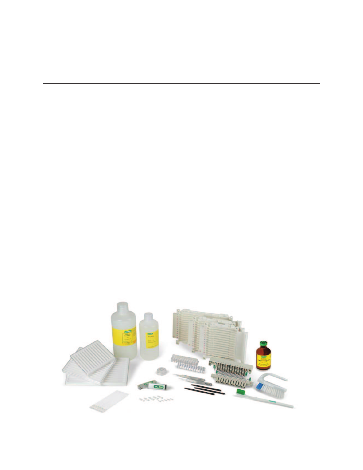
The PROTEAN i12 IEF system includes the accessories listed in Table 1.2 and shown in Figure 1.3.
Table 1.2. Accessories for the PROTEAN i12 system. Accessories not included may be purchased separately (see Appendix G,
Ordering Information).
Component Quantity Description
Included with the PROTEAN i12 IEF System
i12 focusing trays 1 each For IEF (and rehydration) of 1–12 IPG strips; each tray includes 2 IPG
with IPG strip retainers (7, 11, and 17 cm) strip retainers to maintain contact between the IPG strip and
electrodes for IEF with the gel-side down configuration
Electrode assemblies 1 set each Positive (+) and negative (-) electrode assemblies; provide contact
between each IPG strip and its power supply
i12 rehydration/equilibration trays 25 each Disposable trays for passive rehydration and equilibration of IPG
(7, 11, and 17 cm) strips
Electrode wicks 100 gel-side up Collect salts and other charged impurities as well as proteins with
500 gel-side down isoelectric points (pI) outside the pH range of the IPG strip (use is
recommended)
ReadyStrip™ IPG strips 12 each Medium for isoelectric separation of proteins
pH 3–10 (7, 11, and 17 cm)
Mineral oil 500 ml For overlay of IPG strips to prevent dehydration
Forceps 2 pair For manipulation of IPG strips
Cleaning brushes Set of 2 For cleaning the focusing tray and electrode assemblies
Cleaning concentrate 1 L For cleaning the focusing tray and electrode assemblies
USB flash drive 2 Memory data storage device integrated with a USB interface; for
storage and transfer of data from the PROTEAN i12 IEF cell
Stylus 3 Used to manipulate touch screen (user interface)
Leveling bubble 1 Indicates whether the IEF cell is level
Power cord 1 Connects the IEF cell to a power source
ReadyPrep™ rehydration buffer 10 ml For rehydration and sample loading of IPG strips
Not Included with the PROTEAN i12 IEF System
i12 focusing trays (13, 18, and 24 cm) For IEF (and rehydration) of 1–12 IPG strips;
each tray includes 2 IPG strip retainers
i12 rehydration/equilibration trays (13, 18, and 24 cm) Disposable trays for passive rehydration and
equilibration of IPG strips
Sample cup holder and sample cups For cup loading of samples
Cleaning concentrate
i12 rehydration/equlibration trays
ReadyStrip IPG strips
Fig. 1.3. PROTEAN i12 accessories.
Mineral oil
IPG strip retainers
Leveling bubble
USB flash drive
Electrode wicks
i12 focusing trays
ReadyPrep rehydration buffer
Electrode assemblies
Forceps
Styluses
Cleaning brushes
| 3PROTEAN i12 IEF System Instruction Manual | 3
Page 8

Chapter 1 PROTEAN i12 IEF System
i12 Focusing Tray
Channels in the i12 focusing tray (Figure 1.4) hold IPG strips for IEF. Each focusing tray accommodates up
to 12 IPG strips. Separate trays are available for 7, 11, 13, 17, 18, and 24 cm IPG strips. For flexibility, the
PROTEAN i12 focusing tray and electrode assemblies accommodate all run configurations: gel-side down
or up, with in-gel sample loading or sample cup loading. Each focusing tray holds one negative (-) and one
positive (+) electrode assembly. Focusing trays can also be used for rehydration of IPG strips.
Electrode Assemblies
The electrode assemblies (Figure 1.4) each include 12 individual sets of negative and positive electrodes. The
assemblies attach to the focusing tray to provide contact between each IPG strip and its power supply. They
accommodate all focusing tray sizes.
Positive (+) electrode assembly
Release clip with green tab
Orientation pin
Release clip with green tab
Focusing tray
Tray positioning
stop
Fig. 1.4. PROTEAN i12 focusing tray and electrode assemblies.
IPG strip positioning stop
Channel
Release clip
with green tab
Release clip
with green tab
Negative (-) electrode assembly
4 | PROTEAN i12 IEF System Instruction Manual4 |
Page 9

Chapter 1 PROTEAN IEF System
1.2 Unpacking and Setup
1. Carefully inspect the shipping container for any damage that may have occurred during shipping. Severe
damage to a container may indicate damage to its contents. If you suspect damage to the contents,
immediately file a claim with the carrier in accordance with their instructions before contacting Bio-Rad
Laboratories.
2. Open the shipping carton and lift the content out of its packing. Inspect the instrument for external
damage. If any part is missing or damaged, contact Bio-Rad Laboratories immediately.
3. Place the PROTEAN i12 IEF cell on a firm, flat surface.
a. Position the cell so that there is access to the USB ports (back panel) and power switch (right panel).
b. To ensure adequate cooling, be sure that there is ≥6 cm clearance around the unit. DO NOT block the
fan vents.
c. Make sure the system is on a level surface. Place the leveling bubble in the center of the cooling
platform and adjust the instrument leveling feet as needed.
4. Connect the cell to a three-prong, grounded AC outlet using the power cord provided with the cell.
Do not place cloth or absorbent pads underneath the instrument. These or other loose
items may be pulled into the fan intake, causing damage to the unit due to overheating
and voiding the warranty.
1.3 Workflow
Figure 1.5 summarizes the workflow described in this manual. For best results, use the reagents and
protocols available in the ReadyPrep 2-D starter kit (catalog #163-2105) to familiarize yourself with the
2-D process and operation of the PROTEAN i12 IEF cell. For more details about performing 2-D
electrophoresis, please refer to bulletin 2651, 2-D Electrophoresis for Proteomics: A Methods and Product
Manual.
Fig. 1.5. IEF workflow overview.
| 5PROTEAN i12 IEF System Instruction Manual | 5
Page 10

6 | PROTEAN i12 IEF System Instruction Manual6 |
Page 11

2
Basic Operation
2.1 Setup
For best results, use the reagents and protocols available in the ReadyPrep™
2-D starter kit (catalog #163-2105) to familiarize yourself with the 2-D
process and operation of the PROTEAN® i12™ IEF cell.
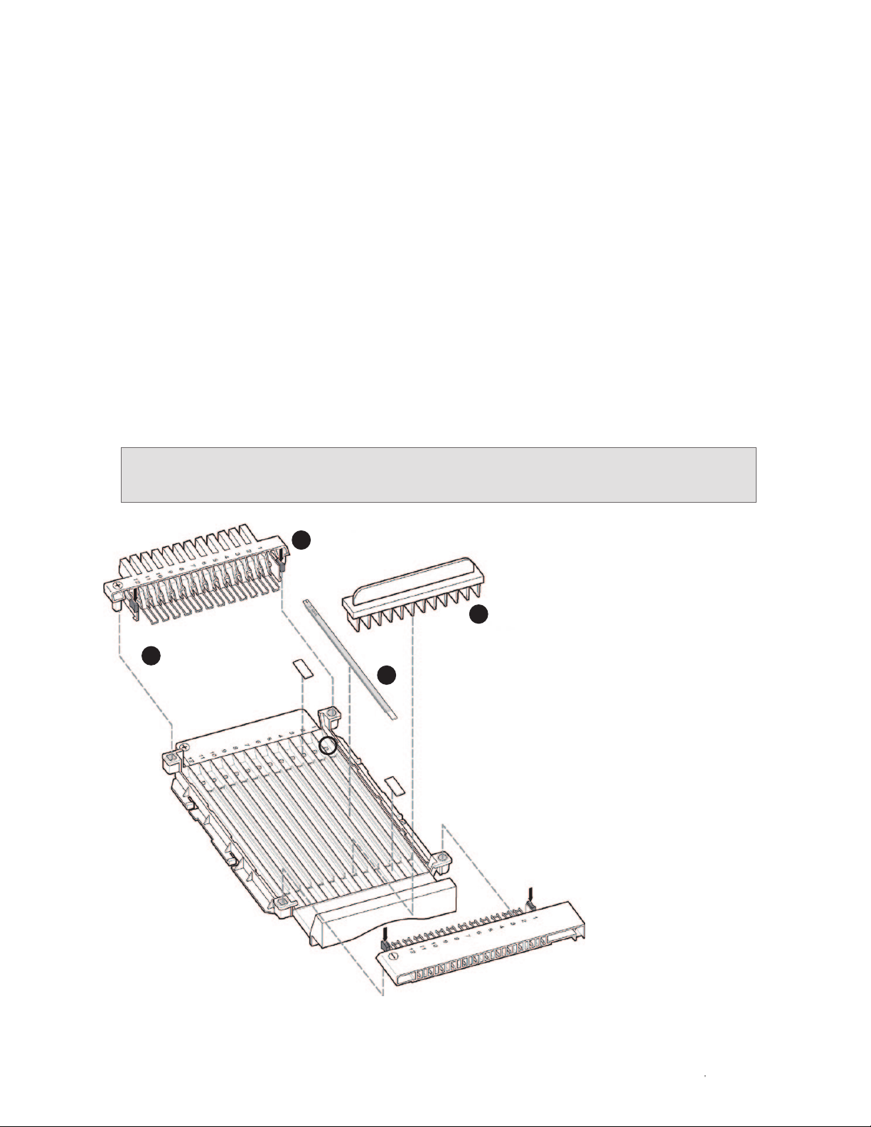
2.1.1 i12™ Focusing Tray and Electrode Assemblies
The PROTEAN i12 electrode assemblies have 12 electrodes that fit the 12
channels in the i12 focusing tray. Each electrode accommodates the use of
electrode wicks and both the gel side-up and gel side-down IEF configurations: a
bridge on each electrode fits into the recessed area of the focusing tray to create
the flat surface required for the gel-side down configuration, and the electrodes
are spring-loaded, which allows them to exert a gentle downward pressure for
the gel-side up configuration. Several features of the electrode assemblies ensure
their correct and complete attachment to the focusing tray (Figure 2.1):
■
Square and round orientation pins in the electrode assemblies ensure correct
positioning of the cathode and anode in the focusing tray
■
Release clips secure the electrode assemblies onto the focusing tray
■
Green tabs on the release clips help push the electrode assemblies into place
To place the electrode assemblies in the i12 focusing tray:
1. Grasp the electrode assembly by the release clips and position the orientation
pins as shown in Figure 2.1.
2. Push down on the green tabs until the locks click into place on the walls of
the focusing tray. With the gel-side down configuration, make sure that each
electrode is properly seated in the recessed area of the focusing tray.
To remove electrode assemblies from the focusing tray, grasp the green tabs
on the release clips and gently squeeze inward.
PROTEAN i12 IEF System Instruction Manual | 7
Page 12

Chapter 2 Basic Operation
Positive (+) electrode assembly
Release clip with green tab
Orientation
pin
Release clip with green tab
IPG strip positioning stop
Channel
Focusing tray
Fig. 2.1. Placement of an electrode assembly onto
the i12 focusing tray.
2.1.2 Connecting the Electrodes
1. Position the assembly on the Peltier platform. Use the positioning guides and stops on the platform and
focusing tray as guides (Figure 2.2, see inset).
2. Slide the assembly toward the positive (+) end until the positive (+) electrode assembly is completely
inserted. When the the tray positioning stop reaches the positioning guide on the platform, the assembly
is seated correctly (Figure 2.2).
3. Make sure the negative pin on the negative (-) electrode is in direct contact with the metal gounding strip
on the instrument (Figure 2.2).
Platform
positioning guide
Tray positioning
stop
Tray positioning
guide
Tray positioning
stop
Platform
positioning guide
Instrument
platform
Positioning the tray
Metal grounding strip
Negative pin
Fig. 2.2. Connecting the electrodes.
PROTEAN i12 IEF System Instruction Manual8 |
Page 13
Chapter 2 Basic Operation
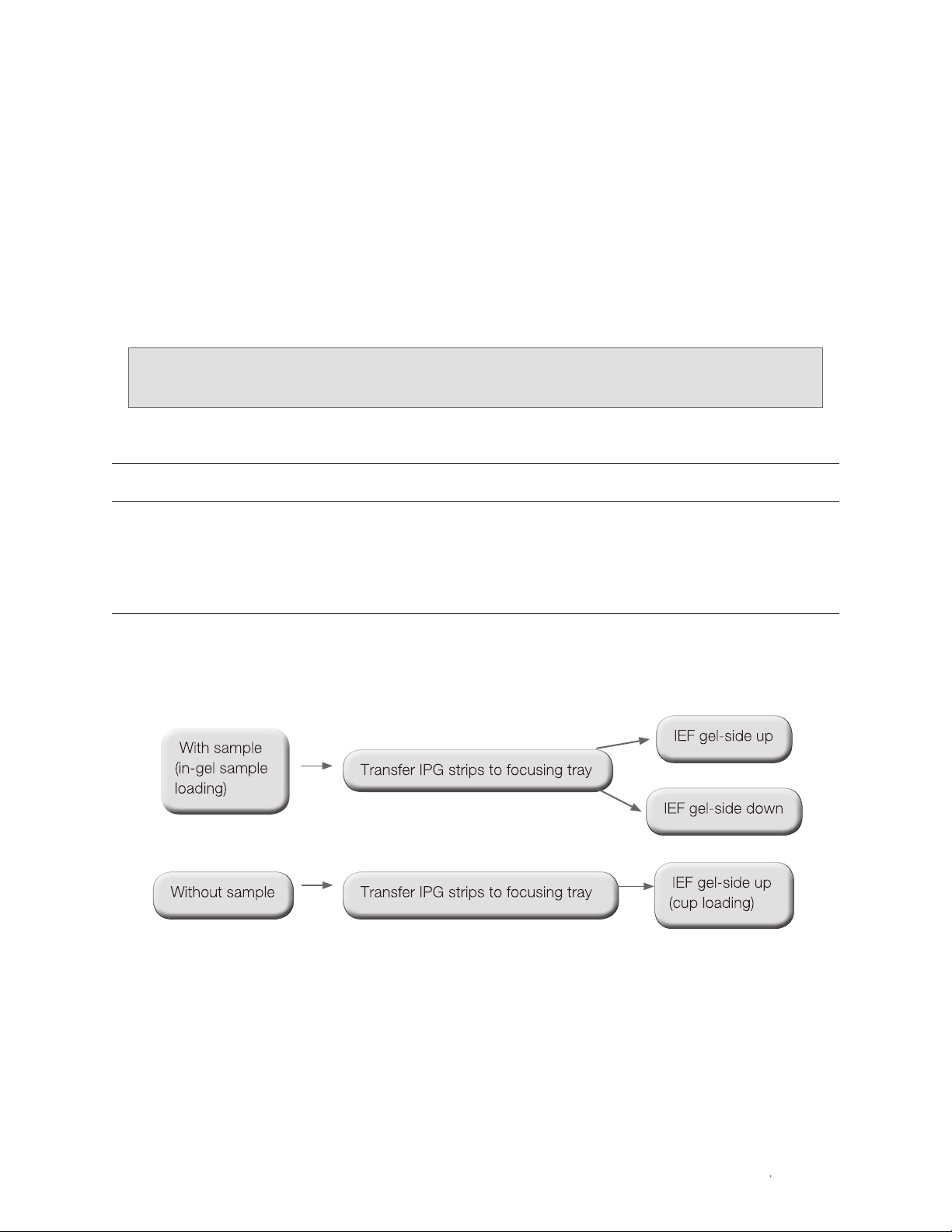
2.2 IPG Strip Rehydration and Sample Application
The choice of rehydration and sample loading method (in-gel sample loading or cup loading) and IPG strip
configuration (gel-side down or gel-side up) dictates the workflow for the run. The first step is to rehydrate
the IPG strips in rehydration solution, with or without sample (Table 2.1).
IPG strips can be rehydrated in either the i12 rehydration/equilibration trays or the i12 focusing tray:
■
For rehydration in rehydration/equilibration trays, see Section 2.2.1
■
For rehydration in the focusing tray, see Section 2.2.2. Rehydration in the focusing tray with in-gel sample
application can be programmed as part of the IEF run
See Appendix B, Sample Loading Methods and Running Configurations, for guidelines for
selecting the sample loading method and IPG strip configuration.
Table 2.1. Rehydration volumes, sample loads, and mineral oil volumes. The values listed are recommendations. Optimum
sample load depends on sample type. See Appendix A, Reagent and Sample Preparation, for more details.
IPG Strip Length
7 cm 11 cm 17 cm 18 cm 24 cm
Rehydration Solution 125 μl 200 μl 300 μl 315 μl 450 μl
Protein Load
Coomassie (Brilliant) Blue 50–100 µg 100–200 µg 200–400 µg 200–400 µg 400–800 µg
Fluorescent stains 5–100 µg 20–200 µg 50–400 µg 50–400 µg 80–800 µg
Silver stains 5–20 µg 20–50 µg 50–80 µg 50–80 µg 80–150 µg
Mineral Oil 4 ml 5 ml 7 ml 7 ml 9 ml
2.2.1 IPG Strip Rehydration in the Rehydration/Equilibration Tray Followed by IEF
Rehydration IEF
For the rehydration step:
1. Pipet the rehydration solution (with or without sample, see Table 2.1 for volumes and protein loads) along
the center of the channel(s) of the i12 rehydration/equilibration tray. Take care to not introduce air bubbles
when expelling the solution.
2. Using forceps, remove the cover sheet from the IPG strip, then gently place the IPG strip gel-side down
onto the solution in the channel. Move the IPG strip back and forth slightly to ensure that the solution is
distributed along the length of the IPG strips. Take care to not trap air bubbles beneath the IPG strip.
| 9PROTEAN i12 IEF System Instruction Manual | 9
Page 14

Chapter 2 Basic Operation
3. Overlay each IPG strip with mineral oil to prevent evaporation and precipitation of urea during rehydration
(see Table 2.1 for recommended volumes). Apply the mineral oil to both ends of the channel and allow it
to flow toward the middle of the channel. IPG strips can be left to rehydrate for up to 1 hr before adding
the mineral oil.
4. Cover the tray and leave it on a level bench overnight (12–18 hr) for complete rehydration.
5. Transfer the rehydrated IPG strips to the focusing tray for IEF (see below).
IEF with Gel-Side Up
For IEF of IPG strips that were rehydrated in the presence of sample (in-gel loading):
1. Using forceps, remove the IPG strips from the rehydration tray, remove excess mineral oil, and place the
rehydrated IPG strips gel-side up in the channels of the focusing tray (Figure 2.3, A). Position the positive
(+) ends of the IPG strips against the positioning stops in each channel.
2. (Recommended) Wet the gel-side up wicks (notched) with distilled or deionized water and blot off excess
water. Use two wicks per IPG strip: place a wick at each end of each IPG strip (Figure 2.3, B).
3. Position the electrode assemblies in the focusing tray and press down on the green tabs to snap the
electrode assemblies into place (Figure 2.3, C). Place the focusing tray with the rehydrated IPG strips on
the Peltier platform and connect the electrodes to the instrument (see Section 2.1, Setup).
4. Overlay each IPG strip with mineral oil (see Table 2.1 for recommended volumes).
5. Select or program the protocol(s) and start the run (see Section 2.3, Starting the Run).
Place IPG strips gel-side up in channel of focusing tray.
A
(Recommended) Place wet electrode
B
wicks on both ends of the IPG strip.
IPG strip positioning stop
Place electrode assemblies in
C
the focusing tray. Press down
on the green tabs to snap the
assemblies into place.
Fig. 2.3. Placement of an IPG strip gel-side up into the i12 focusing tray.
PROTEAN i12 IEF System Instruction Manual10 |
Page 15
Chapter 2 Basic Operation
IEF with Gel-Side Down
For IEF of IPG strips that were rehydrated in the presence of sample (in-gel sample loading):
1. Position the electrode assemblies in the focusing tray and press down on the green tabs to snap the
electrode assemblies into place (Figure 2.4, A; see Section 2.1.1, i12 Focusing Tray and Electrode
Assemblies).
2. (Recommended) Wet the rectangular (gel-side down) wicks with distilled or deionized water and blot off
excess water. Use two wicks per IPG strip: place a wick on top of each electrode (Figure 2.4, B).
3. Using forceps, place the rehydrated IPG strips gel-side down in the channels of the focusing tray (Figure
2.4, C). Position the positive (+) ends of the IPG strips against the positioning stops in each channel.
4. Place the focusing tray on the Peltier platform and connect the electrodes to the instrument (see Section
2.1.2, Connecting the Electrodes).
5. Overlay each IPG strip with mineral oil (see Table 2.1 for recommended volumes).
6. Place the IPG strip retainers on top of the IPG strips at both the positive and the negative ends (Figure
2.4, D). Without IPG strip retainers in place, gases formed during electrolysis may lift IPG strips off the
electrodes, interrupting electrical contact.
7. Select or program the protocol(s) and start the run (see Section 2.3, Starting the Run).
To avoid movement of the IPG strip retainers, which can damage the IPG strips, place them into
the focusing tray after the focusing tray has been secured on the Peltier platform.
(Recommended) Place
B
wet electrode wicks in the
channels of the focusing tray.
Place both electrode assemblies in the focusing tray. Press down
A
on the green tabs to snap the assemblies into place.
Place the focusing tray onto the Peltier platform,
D
connect the electrodes, and then place 2 IPG strip
retainers on top of the IPG strips.
Place IPG strips gel-side down in the channels of the
C
focusing tray.
IPG strip positioning stop
Fig. 2.4. Placement of an IPG strip gel-side down into the i12 focusing tray.
| 11PROTEAN i12 IEF System Instruction Manual | 11
Page 16
Chapter 2 Basic Operation
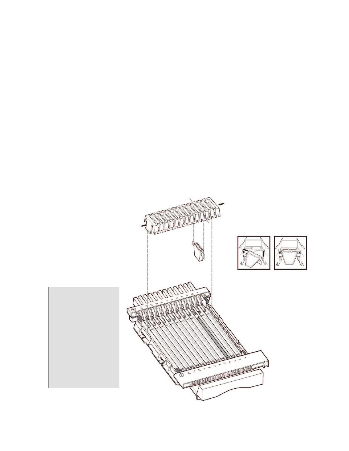
Cup Loading (IEF with Gel-Side Up)
Sample cups (catalog #164-6020) offer an alternative method of sample loading. Their use can improve
resolution, especially at extreme pH ranges (see Appendix B, Sample Loading Methods and Running
Configurations, for guidelines on when to use cup loading). The PROTEAN i12 sample cup assembly
consists of a sample cup holder that holds 1–12 disposable sample cups.
1. Using forceps, place the rehydrated IPG strips gel-side up in the channels of the focusing tray (Figure 2.3,
A). Position the positive (+) end of the IPG strips against the positioning stops in each channel.
2. (Recommended) Wet the gel-side up electrode wicks (notched) with deionized water and blot off excess
water. Use two wicks per IPG strip: place a wick at each end of each IPG strip (Figure 2.3, B).
3. Position the electrode assemblies in the focusing tray and press down on the green tabs to snap the
electrode assemblies into place (Figure 2.3, C). Place the focusing tray on the Peltier platform and
connect the electrodes to the instrument (see Section 2.1.2, Connecting the Electrodes).
4. Prepare the sample cup assembly by placing the sample cups into the slots of the sample cup holder
corresponding to the channel with the rehydrated IPG strip (Figure 2.5).
5. Clamp the sample cup assembly onto the edges of the focusing tray, on top of the IPG strips and next to
either electrode (Figure 2.5). (Placement depends on the pH gradient and the sample. See Appendix B,
Sample Loading Methods and Running Configurations.)
6. Load 25–250 µl sample
into the sample cups (larger
volumes of dilute samples
may be loaded, up to 400 µl).
Overlay both the sample in
the sample cup and the IPG
strip with mineral oil.
7. Select or program the
protocol(s) and start the run
(see Section 2.3, Starting the
Run).
Two flexible arms on
the sample cup holder
apply gentle pressure
onto the sample cup to
ensure a complete seal
between the IPG strip
and the sample cup.
Once the sample cup
holder is positioned,
any horizontal
movement will damage
the IPG strips.
Sample cup holder
Sample cup
Insert sample cup at an angle
12 |
12 |
Fig. 2.5. Placement of the sample cup assembly onto the focusing tray.
PROTEAN i12 IEF System Instruction Manual
Page 17

Chapter 2 Basic Operation
2.2.2 IPG Strip Rehydration in the Focusing Tray Followed by IEF
Rehydration can be programmed as a part of the run, followed by the IEF protocols. Alternatively, the IPG
strips can be rehydrated independently and the protocol(s) started when most convenient.
Rehydration IEF
1. Position the electrode assemblies in the focusing tray as described in Section 2.1.1.
2. Pipet the rehydration solution containing the protein sample along the center of the channel(s) of the
focusing tray (see Table 2.1 for recommended volumes and protein loads). Do not introduce air bubbles
when expelling the solution.
3. Using forceps, remove the cover sheet from the IPG strip, then gently place the IPG strip gel-side down
onto the sample in the channel of the tray. To ensure even rehydration, move the IPG strips back and
forth slightly to distribute the solution along the lengths of the IPG strips. Check that no bubbles are
trapped beneath the IPG strip and that some rehydration solution extends beyond the electrode contacts.
4. Place the focusing tray with the IPG strips on the Peltier platform and connect the electrodes to the
instrument (see Section 2.1.2).
5. Immediately overlay each IPG strip with mineral oil to prevent evaporation and precipitation of urea during
rehydration. Apply the mineral oil to both ends of the channel and allow it to flow toward the middle of the
channel. See Table 2.1 for recommended volumes of mineral oil.
6. Position the IPG strip retainers on top of the IPG strips at both the anode and the cathode to maintain
electrical contact with the IPG strips during IEF. Without the IPG strip retainers, electrolysis gasses may lift
IPG strips off of the electrodes, interrupting electrical contact.
Place IPG strip retainers after the focusing tray has been placed into the instrument to avoid
movement of the strip retainers.
7. Rehydration in the focusing tray with in-gel sample application can be programmed as a part of the IEF
run or be performed separately. To program rehydration as part of the run:
a. Select or program the protocol(s) for the lanes containing IPG strips (see Section 3.1).
b. Program the global rehydration conditions in the Run Settings screen (see Section 3.2). If electrode
wicks are used, include a pause to insert electrode wicks when the rehydration step is completed.
c. Start the run (see Section 2.3, Starting the Run).
For rehydration not programmed as part of the run, leave the tray on the Peltier platform or on a
level bench overnight (12–18 hr) for complete rehydration.
Global rehydration conditions are applied to all IPG strips in a run.
| 13PROTEAN i12 IEF System Instruction Manual | 13
Page 18
Chapter 2 Basic Operation
2.3 Starting the Run
Turn on the PROTEAN i12 IEF cell by pressing the power switch on the right side of the instrument. A
self-diagnostic program runs for approximately 10 sec. On the user interface, a message reads Self Test in
Progress. If a component fails, the diagnostic program stops, and an error message appears (see Chapter 7,
Troubleshooting).
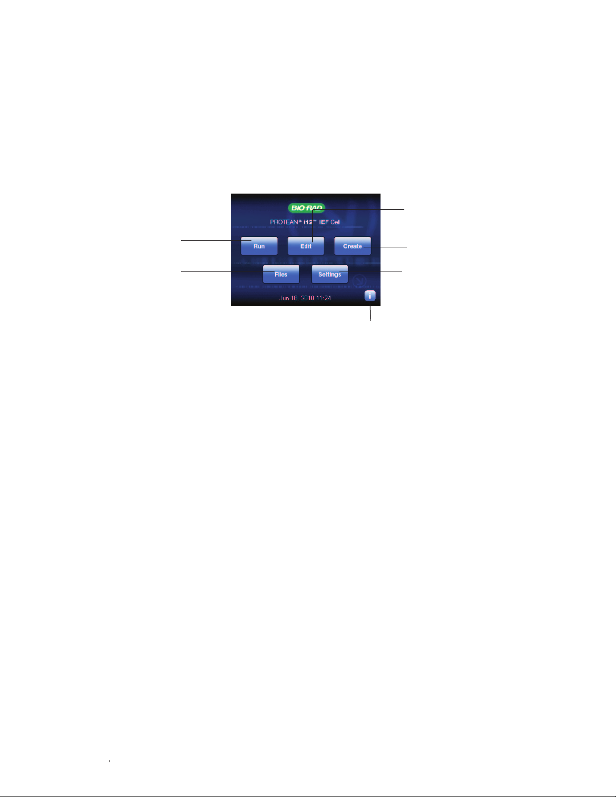
Once the cell is powered on, the Main screen appears (Figure 2.6). Start the run by selecting one of the
options described in Figure 2.6.
Edit an existing protocol (Chapter 4)
Run an existing protocol
(Chapter 3)
Manage files and folders
(Chapter 5)
Fig. 2.6. PROTEAN i12 IEF cell Main screen.
Create a new protocol with up to
10 steps in the Edit Protocol screen
(Chapter 4)
Set default parameters and customize
screens (Chapter 5)
View onboard help
14 | PROTEAN i12 IEF System Instruction Manual
14 |
Page 19

3
Chapter Title HereRunning a Protocol
Select Run in the Main screen to select, assign, and run an existing
(preprogrammed or user-defined) protocol. Multiple protocols can be assigned
simultaneously to different IPG strips in a single run. Power is not applied to lanes
without assigned protocols (these are designated Not Assigned).
This chapter describes how to select a protocol, enter run and sample details,
and start a run (Figure 3.1). For details about creating or editing protocols, refer to
Chapters 4 and 5.
Fig. 3.1. General workflow for running an existing protocol.
PROTEAN i12 IEF System Instruction Manual | 15
Page 20

Chapter 3 Running a Protocol
3.1 Workflow
See Section 3.2, Screen Details, for details about the options and functions for each screen.
16 |
PROTEAN i12 IEF System Instruction Manual
Page 21

Chapter 3 Running a Protocol
PROTEAN i12 IEF System Instruction Manual | 17
Page 22

Chapter 3 Running a Protocol
3.2 Screen Details
Screen Details/Procedure
Main Run — opens the protocol assignment screen for selection of
protocol(s) stored in the internal memory or on a USB flash drive
(only preprogrammed Bio-Rad protocols or saved .prt protocol files
appear).
Protocol Assignment Screens
Protocol Assignment
Display the available lanes (in a 12- or 6-lane format), available
memory devices, and Bio-Rad folder (with preprogrammed
protocols).
To assign a protocol to a lane(s):
1. Touch any lane to select it. Selected lanes are highlighted in blue.
2. Select the memory device/folder for display of stored protocols.
3. Select the protocol, which is highlighted and immediately assigned
to the highlighted lane(s). To select a preprogrammed protocol,
select the Bio-Rad folder and then select the protocols for the IPG
strip length. The protocols appear in the content box.
4. Repeat this procedure to assign different protocols to different
lanes.
Lanes Assigned Displays the name of the assigned protocol in each selected
(highlighted) lane.
View Protocol — displays the details of the protocol highlighted in
the content box
Run — opens the Run Settings screen
18 |
18 |
PROTEAN i12 IEF System Instruction Manual
Page 23

Chapter 3 Running a Protocol
Screen Details/Procedure
View Protocol Displays the protocol parameters for the selected protocol.
Back — returns to the Lanes Assigned screen
To create and edit protocols, use the Create or Edit option in
the Main screen (see Chapter 4).
Run Settings Displays the name of the run data file and offers options for setting
the focusing temperature and conditions for a global rehydration step.
It also offers links to options for entering sample and IPG strip details.
The 12 lane numbers appear, with active lanes listed in boldface and
unassigned lanes grayed out.
To enter or change the name of the run data file, select the text box
next to Start Run to access the keyboard and enter the name.
Focusing Temp. Deg. C — sets the temperature for IEF (10–25ºC,
default 20ºC)
Rehydration — select Yes to program a rehydration step
Rehydration parameters:
■
Hrs — rehydration time (0–99:59 hr, default 12 hr)
■
Volts — rehydration voltage (0 or 50–100 V, default 0 V)
■
Temp. Deg. C — rehydration temperature (10–25ºC, default 20ºC)
■
Pause after rehydration — select Yes if a pause is required for
insertion of electrode wicks
Start — starts the run
Strip Details — opens the Strip Details screen
Sample Details — opens the Sample Details screen
Protocol details, data points, and sample and IPG strip details for
each assigned lane are included in the run data file. Run data files
with the same name are overwritten if saved in the same folder. When
the run is complete, the option to rename the run data file and select
a location will be available. The default storage location for a run data
file is Internal Drive/Bio-Rad Data.
| 19PROTEAN i12 IEF System Instruction Manual | 19
Page 24

Chapter 3 Running a Protocol
Screen Details/Procedure
Strip Details
Used to enter information about the IPG strips (pH range, length, lot,
etc.) and samples in the assigned lanes. Press an assigned lane to
select it and then press Enter Text.
Enter Text — opens the keyboard used to enter the details
Clear All Lanes — removes all entries
OK — accepts the entered details and returns to the Run Settings
screen. The entered strip detail is included with the saved run data file
Sample Details
Save Sample — saves the entered sample details in a specified
location and folder. Sample details are saved to the lane that was
specified
To import an existing sample detail file:
1. Press Import Sample to access previously saved sample detail
files.
2. Select the location and the sample detail file, then press Load
Sample. The sample details populate the assigned lanes.
Run Screens
Rehydration in Progress Displays the rehydration conditions and the time remaining during
rehydration. When the rehydration time has elapsed, the IEF run
starts unless a pause is selected. If a rehydration pause is selected,
the message, Rehydration Completed appears.
Run Protocol — terminates rehydration and starts step 1 of the
protocol(s) in the assigned lane(s)
Back — terminates rehydration and returns to the Run Settings
screen
Running Displays active parameter values for each assigned lane, the time
remaining for the active step, and the total accumulated V-hr for
the run. View Protocol, View Data, and View Graph open the
respective screens.
20 |
20 |
Pause — pauses the run and opens the System Paused screen,
where the run may be continued or terminated
End Run — terminates the run and opens the End Of Run screen
PROTEAN i12 IEF System Instruction Manual
Page 25

Screen Details/Procedure
View Data
Displays data recorded for each assigned lane while the run is in
progress. The information for the first assigned lane appears; press
the remaining assigned lane numbers to display the related details.
Toggle between the screens to review all the information for the
highlighted lane.
View Data — displays all the data points for the selected lane. Data
points are collected at 5 min intervals unless otherwise specified in
the Settings screen. The collection frequency range is 1–15 min per
View Graph
data point
View Graph — displays a graph of voltage and current as a function
of time for the selected lane
View Protocol — displays the protocol details for the selected lane
Back — returns to the Running screen
Chapter 3 Running a Protocol
View Protocol
System Paused Appears if the run is paused (for example, to safely remove
completed or faulty IPG strips, remove/add electrode wicks, etc.).
End Run — terminates the run
Continue — continues the run
| 21PROTEAN i12 IEF System Instruction ManualPROTEAN i12 IEF System Instruction Manual | 21
Page 26

Chapter 3 Running a Protocol
Screen Details/Procedure
End of Run Appears at the end of a run and displays the total V-hr for each
assigned lane.
View Results — opens the View Data screen with options to View
Protocol and View Graph for each of the assigned lanes
Run Again — returns to the Run Settings screen
Export Results — opens the Save Data As screen
Main — opens the Main screen and automatically saves the run data
file in the Bio-Rad data folder. Run data files with the same name are
overwritten; to rename the file, select Export Results
Save Data As Used to rename and export the run data (.dat) file to a specific
location in the internal memory or to a USB flash drive.
1. Select a storage location and select or create a folder.
2. Press Save to open the alphanumeric keyboard. The run data file
name appears. Select Save to accept the name, or enter a new
name and select Save.
3. The run data file is saved in the selected location, and the Main
screen appears.
The run data file (.dat) is a text file that can be opened and imported into a spreadsheet. For details on the file
and how to display the data with Excel software, see Chapter 6, Data Export and Analysis.
22 | PROTEAN i12 IEF System Instruction Manual22 |
Page 27

4
Creating and Editing
Protocols
Use the Edit and Create options in the Main screen to edit an existing protocol
or create a new protocol. Up to ten steps can be programmed and stored in the
internal memory or a USB flash drive.
4.1 Workflow
PROTEAN i12 IEF System Instruction Manual | 23
Page 28

Chapter 4 Creating and Editing Protocols
4.2 Screen Details
Screen Details/Procedure
Main Edit — opens the Select Template screen with options for editing an
existing protocol
Create — opens the New Protocol screen with options for creating
a protocol
Bio-Rad protocols cannot be overwritten. Save any changes as
a new protocol.
Select Template Used to select the protocol that will serve as the template (the
protocol you wish to edit).
Select the memory device, the folder, then the protocol. The Edit
Protocol screen opens, displaying the name and parameters of the
selected protocol.
New Protocol
Edit Protocol
Displays the steps and settings for a new or template protocol: the
New Protocol screen displays a single step, and the Edit Protocol
screen displays steps in a saved protocol. Press Add Step Above or
Add Step Below to add steps as needed (a protocol can contain up
to ten steps).
Touch a cell in the table to edit the settings for the parameters listed
(see Appendix C, IEF Protocols for more details):
Voltage — 0 V or 50–10,000 V
Gradient:
■
Rapid — voltage limited by the set current value
■
Linear — voltage increases in a linear fashion from the starting
voltage to the maximum set voltage. Linearity is not achieved if the
current limit is reached before the required voltage is reached
■
Gradual — bases the voltage change on a delayed voltage
ramping algorithm that gradually increases over the time specified
■
Hold — maintains the voltage, recommended at a field strength
of ~50 V/cm of strip length, until the run is stopped manually. Can
be used as the final step to prevent protein diffusion when IEF is
complete. Steps cannot be added beyond the hold step
µAmps — current (0–100 µA)
24 | PROTEAN i12 IEF System Instruction Manual24 |
Time/VHr — 00:01–99:59 hr or 1–999,999 V-hr
Units — toggle between HH:MM and Volt Hr; previously entered
values reset to 00:01 and 1, respectively
OK — opens the Save Protocol As screen
Page 29

Chapter 4 Creating and Editing Protocols
Screen Details/Procedure
Save Protocol As To save the new or edited protocol:
1. Select the location and select or create a folder.
2. Press Save to access the alphanumeric keyboard, where the
name is displayed at the top of the screen.
3. Enter or edit the name of the protocol, then press Save.
4. The Confirm Save screen appears.
Confirm Save Displays location to which file will be saved.
Cancel — returns to the Save Protocol screen
Confirm Save — saves and then opens the Main screen. Overwrite
appears if the same file name is being saved to the same location
| 25PROTEAN i12 IEF System Instruction Manual
| 25
Page 30

26 | PROTEAN i12 IEF System Instruction Manual26 |
Page 31

Setting Defaults and
5
Managing Folders
5.1 Setting Default Parameters (Settings)
Use the Settings options to set default parameters and to customize screens:
■
System Time — sets the month, day, year, or time. Use the right and left arrow
buttons to make adjustments
■
Log Interval (min) — sets the data collection frequency (1–15 min; default
5 min). Select the field and use the up and down arrows to change the value
■
Default Run Name — name automatically associated with a run, and the run
data are stored in the Bio-Rad Data folder in the internal memory when the run
is complete. Stored run data files with names identical to new files being stored
in the same location are overwritten
■
Rehydration Step — sets global rehydration step defaults. If the rehydration
step is selected, all rehydration step options appear in the Run Settings screen.
If not selected, the details can be assigned in the Run Settings screen
■
Pause after Rehydrate — select to include a pause after rehydration
■
Default rehyd. time — sets the rehydration time (0–99 hr; default 12 hr)
■
Rehyd. temperature — sets the rehydration temperature (10–25ºC; default
20ºC)
■
Rehyd. voltage — sets the voltage for rehydration (0 V, 50–100 V; default 0 V)
PROTEAN i12 IEF System Instruction Manual | 27| 27PROTEAN i12 IEF System Instruction Manual
| 27
Page 32

Chapter 5 Setting Defaults and Managing Folders
Save Settings — saves the settings as displayed
More Settings — touch screen calibration and firmware updates
Strip Part Numbers — lists the part numbers of ReadyStrip™ IPG strips (based on length and pH range)
If changes are made and Save Settings is not pressed, the new values are implemented (except
System Time) in the current run, but they revert to the previous settings when the system is shut
down.
5.2 Managing Files and Folders (Files)
The PROTEAN® i12™ IEF cell stores saved and
preprogrammed protocols and run data and sample
details files. Use the options under Files to:
■
Delete files and folders
■
Copy files to a different location
■
Create new folders
5.2.1 Navigating the Files Structure
1. Press Files on the Main screen.
2. Select the drive.
3. Select a folder to display its contents.
■
View File Type — displays files of a certain type
■
Create Folder — creates a new folder
■
Delete Folder — opens the Delete Confirmation
screen and options to Cancel or Delete
■
Main — returns to the Main screen
4. Select a file. The file name is highlighted and
options to Delete File and Copy File appear.
■
Delete File — opens the Delete Confirmation
screen and options to Cancel or Delete
■
Copy File — opens the Copy File To window
(see Section 5.2.2)
28 | PROTEAN i12 IEF System Instruction Manual28 |
Page 33

5.2.2 Copying Files
A file can be copied to the same folder and location
(if saved with a new name) or to a different folder or
different location using the same name or a different
name.
1. Select a file following the workflow in Section
5.2.1.
2. Press Copy File.
3. Select the drive and folder as the location to
which to copy folder (the destination).
4. Press Save File to enable an alphanumeric
keypad with the file name. Confirm the file name
or enter a new name, then press Save.
5. In the confirmation screen, press Confirm Save
or Overwrite to copy the file to the selected
location and return to the Main screen, or press
Cancel to return to the File Copied screen.
Chapter 5 Setting Defaults and Managing Folders
| 29PROTEAN i12 IEF System Instruction Manual | 29
Page 34

PROTEAN i12 IEF System Instruction Manual30 |
Page 35

Data Export and
6
Analysis
6.1 File Types
PROTEAN® i12™ software stores three types of files:
■
.dat — run data files, which contain a record of the protocols run, IPG-strip– or
sample-specific information entered by the user, and a continuous record for
each IPG strip of current, voltage, temperature, and V-hr accumulated, as well
as metadata such as the date, time, instrument serial number, firmware, and
software version
■
.prt — protocol files
■
.smp — sample files
Run data files (.dat) can be viewed and manipulated using either Microsoft Excel
software or the PROTEAN i12 Reporter web-based application.
6.2 Export to Microsoft Excel Software
To export data to Excel software:
1. Follow the directions in Section 5.2.2, Copying Files, to copy run data files to
the USB flash drive.
2. Transfer the USB flash drive to a computer (PC) and launch Microsoft Excel.
3. Select File > Open. In the Open dialog, select All Files as the file type. Find
and click the .dat file to select it, then click Open.
4. In the Text Import Wizard, choose Delimited as the file type option, then
click Next and select comma as the delimiter. The .dat file information
appears in an Excel worksheet.
PROTEAN i12 IEF System Instruction Manual | 31
Page 36

Chapter 6 Data Export and Analysis
6.3 Export to PROTEAN i12 Reporter (www.i12Reporter.com)
The PROTEAN i12 Reporter is a web-based application that enables the creation of protocols (.prt files) and
the display of run data files (.dat files) on a remote computer. It can be used to display the electronic run
profiles for each lane, compare data from different runs, and generate and print reports.
Uploading Data
To upload data (.dat) files to the PROTEAN i12 reporter, first load them onto the flash drive from the
PROTEAN i12 cell. Then upload them into the application.
1. Follow the directions in Section 5.2.2, Copying Files, to copy run data files to a USB flash drive.
2. Transfer the USB flash drive to a computer (PC), then launch the browser and the PROTEAN i12 Reporter
application (www.i12Reporter.com).
3. In the PROTEAN i12 Reporter Main page (Figure 6.1), under Upload Your Run Data, click Browse and
navigate to the run data files (.dat). You can upload up to six files at a time.
Fig. 6.1. PROTEAN i12 Reporter Main screen.
4. Select the files and click Upload. The Run Details screen opens. The data appear under tabs across the
top of the page (Figure 6.2). If multiple data files are uploaded, the Compare Lanes tab also appears.
32 | PROTEAN i12 IEF System Instruction Manual32 |
Page 37

Chapter 6 Data Export and Analysis
Viewing Data
To view the data, select the run and the viewing option in the Run Details screen (Figure 6.2):
■
Voltage vs. Time, Current vs. Time or Voltage/Current vs. Time options generate graphs of the data
■
Protocols displays the IEF protocols and any sample or strip information entered for the run
■
Run Data displays the raw data in table format
■
Events shows if the run was paused and when it ended
■
Create Report allows you to customize a report with the data and graphs
Fig. 6.2. PROTEAN i12 Reporter Run Details screen.
Creating Reports
Click Create Report to generate a report of the run data. Use the options in the Create Report screen to
customize your report:
■
Choose how to display a logo, username, affiliation, or copyright
■
Choose which elements to include in the report: run data with events log, protocols, sample and strip
details, or graphs
Click Print Report to print the report from a designated printer.
Click Save Report to save the report as a .pdf file.
| 33PROTEAN i12 IEF System Instruction Manual
PROTEAN i12 IEF System Instruction Manual
| 33
Page 38

Chapter 6 Data Export and Analysis
Viewing and Editing Protocols
On the Main page, under Protocols:
■
Click View Bio-Rad Protocols to open the Bio-Rad Protocols screen, which displays all Bio-Rad
preprogrammed protocols. Click on a protocol to view its details (Figure 6.3). Click Edit Protocol to
edit the settings and save as a new protocol. You can then print the new protocol or upload it into the
PROTEAN i12 IEF cell
■
Click Create New Protocol to open the Create and Edit an IEF protocol screen (Figure 6.4). Use the
options to set the voltage, gradient, and time parameters and create a protocol of up to ten steps
Fig. 6.3. PROTEAN i12 Reporter Bio-Rad Protocols screen.
Fig. 6.4. PROTEAN i12 Reporter Create and Edit Protocol screen.
34 | PROTEAN i12 IEF System Instruction Manual34 |
Page 39

7
Troubleshooting
This chapter offers troubleshooting advice for the PROTEAN® i12™ IEF system.
For further help or advice, please contact the Bio-Rad Technical Support
department.
In the United States, the Technical Support department is open Monday–Friday,
5:00 AM–5:00 PM, Pacific time.
Phone: 1-800-424-6723
Fax: 1-510-741-5802
Email: LSG_TechServ_US@bio-rad.com (for U.S. and international customers)
Online technical support and worldwide contact information are available at
www.consult.bio-rad.com.
PROTEAN i12 IEF System Instruction Manual | 35
Page 40

Chapter 7 Troubleshooting
Table 7.1. Troubleshooting guide.
Problem Cause Solution
No current in a lane Poor contact between IPG strip
and electrode
Make sure the gel side of the IPG
strip is in direct contact with the
electrode. For the gel-side down
configuration, make sure to
use the IPG strip retainers. See
Chapter 2 for proper placement
of IPG strips
No IPG strip in lane Make sure that the lanes
selected for the run contain IPG
strips before starting a run
Incomplete wetting of electrode
wick
Incomplete rehydration of IPG
strip
No current in any lane No contact between electrode
assembly and IPG strips
No contact between electrode
assembly and instrument
No IPG strips in lanes Make sure IPG strips are
Wet the electrode wicks
completely as instructed in
Chapter 2
Check the rehydration volumes
and times for the IPG strips used
Make sure:
■
Electrode assembly is properly
seated in focusing tray
■
IPG strips are positioned
correctly, (for example, that
gel is in direct contact with the
electrode)
Make sure:
■
Gold contact pin of negative (-)
assembly is in direct contact
with cathode bar on instrument
■
Positive (+) assembly is
completely inserted into anode
of instrument
positioned in lanes before
starting a run
36 | PROTEAN i12 IEF System Instruction Manual36 |
No conductivity in IPG strips Make sure IPG strips are
rehydrated with correct reagents
Page 41

Problem Cause Solution
Voltage does not increase
beyond a low value
High levels of ionic contaminants
in rehydration and sample
solutions
Several hours may be needed for
ionic contaminants to leave IPG
strips. Keep salt concentration
below 40 mM
Voltage does not reach the
programmed value or reaches it
very slowly
Programmed voltage may not
be reached due to the sample
composition
No action needed
Chapter 7 Troubleshooting
Ampholyte concentration is
too high. Up to 1% Bio-Lyte®
Lower the ampholyte
concentration
ampholytes may be used,
but ampholytes increase
conductivity; therefore, voltage
will be lower with increasing
concentrations
Error message appears Situation-dependent Shut down the instrument using
the power switch and then
restart it. If this fails to resolve the
issue, contact Bio-Rad Technical
Support
PROTEAN i12 IEF System Instruction Manual | 37
Page 42

PROTEAN i12 IEF System Instruction Manual38 | PROTEAN i12 IEF System Instruction Manual38 | PROTEAN i12 IEF System Instruction Manual
Page 43

Cleaning and
8
Maintenance
PROTEAN® i12™ IEF Cell
The external case is composed of cycoloy (PC/ABS). Keep it clean with
occasional dusting or wiping down with a wet paper towel.
Electrode Assemblies
The electrode assembly holder is made of polycarbonate, and the electrodes
are platinum-plated titanium. To clean the assemblies, remove them from the
focusing tray and rinse with water. Dry them thoroughly before reusing.
i12™ Focusing Trays
To clean the polycarbonate i12 focusing trays, remove the excess mineral oil and
clean with a nonabrasive detergent (for example, Bio-Rad cleaning concentrate)
using the cleaning brushes provided. Rinse the trays thoroughly with deionized
water to remove all detergents. Dry them thoroughly before reusing.
i12 Rehydration/Equilibration Trays
These polystyrene trays are disposable.
Sample Cup Holder and Sample Cups
The sample cup holder and sample cups are made of polycarbonate. The
sample cups are disposable to prevent cross-contamination, but the sample
cup holder can be cleaned and reused. Soak the sample cup holder in Bio-Rad
cleaning concentrate or other mild detergent, rinse it with deionized water, and
dry it thoroughly before reusing.
IPG Strip Retainers
Clean the polycarbonate IPG strip retainers by soaking them in Bio-Rad cleaning
concentrate or other mild detergent. Rinse them with deionized water and dry
them thoroughly before reusing.
PROTEAN i12 IEF System Instruction Manual | 39
Page 44

Appendix A Reagent and Sample Preparation
Rehydration Solution
Prepare or dilute samples into a rehydration or
loading solution that contains urea, a nonionic
or zwitterionic detergent, carrier ampholytes, a
reducing agent such as dithiothreitol (DTT), and
bromophenol blue tracking dye (Table A.1). Optimum
composition depends on the sample, and the
guidelines in Table A.1 should serve as a starting
point for any optimization; additional or alternative
components may be useful as well. For more
comprehensive guidelines, see 2-D Electrophoresis
for Proteomics: a Methods and Product Manual
(bulletin 2651).
To prevent protein contamination, for
example from skin keratin, wear laboratory
gloves when handling IPG strips and the
apparatus and solutions used in IPG strip
preparation.
Protein Sample Loads for IEF
The total amount of protein to load per IPG strip
depends on the sample, the pH range and length of
the IPG strip, and the detection system used (Table
A.2). Below are guidelines for protein loads that
produce acceptable 2-D patterns. In general:
■
Use less protein for silver staining and more for
Coomassie Blue staining. Fluorescent stains such
as Flamingo™, Oriole™, and SYPRO® Ruby have a
wider dynamic range and a correspondingly wider
tolerance for protein load
■
Samples of greater complexity have protein mass
distributed among a larger number of protein
species, and narrow pH ranges have less sample
protein focusing within the pH range of the IPG
strip. Increased protein loads may, therefore, be
required for samples of higher protein complexity
and for narrow-range separations
■
The maximum that can be loaded onto each IPG
strip is 500 µg for 7 cm, 1 mg for 11 cm, 3 mg for
17 cm/18 cm, and 4 mg for 24 cm IPG strips
■
In some cases, overloading of protein is
acceptable and can help to reveal low-abundance
proteins of interest
PROTEAN i12 IEF System Instruction Manual40 | PROTEAN i12 IEF System Instruction Manual
Page 45

Table A.1. IPG strip rehydration solution composition. Vary
the concentrations of the individual components as needed
within the range given.
Concentration
Component Standard Range
Urea 8 M 7–9.5 M
Thiourea — 0–2 M*
CHAPS 2% 1–4%
DTT 50 mM 15–100 mM
Ampholytes (w/v)** 0.2% 0.1–0.4%
Bromophenol blue 0.001% 0.001%
* Thiourea may be used with urea for more effective solubilization
and focusing of hydrophobic proteins (Rabilloud et al. 1997).
**For example, Bio-Lyte ampholytes. Use the pH range
corresponding to the IPG strip selected.
Appendix A Sample and Reagent Preparation
Table A.2. Rehydration volumes and sample loads. Protein concentration in samples prepared for IEF can be difficult to
determine accurately due to interference from detergents, reductants, and other sample components. For best results in protein
quantitation, use the RC DC™ protein assay kit (catalog #500-0121 and #500-0122).
IPG Strip Length
7 cm 11 cm 17 cm 18 cm 24 cm
Rehydration Solution 125 μl 200 μl 300 μl 315 μl 450 μl
Protein Load
Coomassie (Brilliant) Blue 50 –100 µg 100–200 µg 200–400 µg 200–400 µg 400–800 µg
Fluorescent stains 5–100 µg 20–200 µg 50 –400 µg 50–400 µg 80–800 µg
Silver stains 5–20 µg 20–50 µg 50–80 µg 50–80 µg 80–150 µg
PROTEAN i12 IEF System Instruction Manual
| 41
Page 46

Appendix B Sample Loading Methods and Running Configurations
When planning an IEF experiment, one must
choose between a number of methods for sample
application, two options for IPG strip configuration
(gel-side up or gel-side down), and whether to
use electrode wicks. The PROTEAN® i12™ IEF cell
accommodates all of these options using a single
set of electrodes and focusing trays specific for each
commercially available IPG strip length.
Sample Loading Methods
In the original procedure for IEF on IPG strips
described by Görg et al. (1988), IPG strips were
rehydrated without sample, placed gel-side up for
IEF. The sample was applied in sample cups that
were open at the bottom and pressed against the
gel (cup loading).
A procedure was later described (Rabilloud et al.
1994, Sanchez et al. 1997) in which the sample was
included in the rehydration solution and introduced
uniformly along the IPG strip during rehydration
(in-gel loading). In this approach, sample was diluted
into a volume of rehydration solution appropriate for
the IPG strip length, and the IPG strip was placed
over the sample with its gel-side down. This method
simplified sample application and, in some cases,
improved results, particularly with dilute samples or
larger quantities of sample protein. In-gel sample
loading also allows rehydration and IEF to be
conducted as one continuous unattended operation:
if in-gel sample loading is conducted in the focusing
tray with the electrodes in place and in contact with
the gel, the IEF instrument may be programmed to
start IEF without user intervention following suitable
time for rehydration.
In-gel sample loading may also be conducted under
low voltage (active rehydration). In this technique,
in-gel sample loading is conducted in the focusing
tray under a relatively low voltage (50–100 V). This
can improve entry of high molecular weight proteins.
Despite greater complexity in setup, cup loading is
beneficial in certain circumstances. It generally gives
better results when IEF is conducted on basic pH
gradients (for example, pH 7–10) or when optimum
resolution of basic proteins is desired on wide pH
gradients (Görg et al. 2000, Barry et al. 2003).
Cup loading may also be beneficial for samples
containing high molecular weight or hydrophobic
proteins (Görg et al. 2004). Sample cups should be
placed close to an electrode: positive (+) electrode
placement is recommended for basic gradients, and
negative (–) electrode placement is recommended
for acidic gradients. On wide gradients, the best
resolution is generally observed at the end of the IPG
strip opposite the site of cup placement. Use anodic
placement to improve resolution of basic proteins
and cathodic placement for acidic proteins. Factors
influencing the choice of sample loading method are
summarized in Table B.1.
PROTEAN i12 IEF System Instruction Manual42 |42 |
Page 47

Appendix B Sample Loading Methods and Running Configurations
IPG Strip Configuration
The orientation (gel-side up or gel-side down) of
the IPG strip during IEF is largely determined by the
sample loading method employed:
■
Cup loading requires gel-side up strip placement
so that the sample cup may be placed in contact
with the gel surface
■
In-gel sample loading is conducted gel-side down.
If the IEF cell is programmed for an unattended
start following rehydration, IEF must be conducted
gel-side down as well
■
If in-gel sample loading is performed in the
rehydration/equilibration tray, IEF may be
performed either gel-side up or gel-side down.
This is largely a matter of user preference, though
improved resolution may be observed with the gelside up, particularly with higher protein loads
Electrode Wicks
Electrode wicks serve as a sink for ionic sample
contaminants and proteins with pIs outside the pH
range of the IPG strip used. They also prevent drying
of the ends of the IPG strips during IEF. Electrode
wicks may be placed between an electrode and
the IPG strip in either running configuration (with
the PROTEAN i12 IEF cell, specific electrode wicks
are provided for each configuration). Rehydration
in the focusing tray cannot be performed with
electrode wicks in place. In-gel sample loading with
an unattended IEF start, therefore, precludes the
use of electrode wicks. However, a pause may be
programmed following rehydration during which
electrode wicks may be inserted. In many cases, the
use of electrode wicks has little effect on separation
quality, and they may be omitted for convenience in
either running configuration if satisfactory results are
obtained in their absence.
Table B.1. Advantages and disadvantages of different sample loading methods.
Method Advantages Disdvantages
In-Gel Loading Simple sample application Poor resolution of basic proteins
No precipitation at point of sample application
Accommodates dilute samples and larger protein loads
Passive Focusing can follow rehydration without manual intervention Not all proteins, particularly large or
if performed within the IEF instrument hydrophobic proteins, will be taken up
Active More effective with certain proteins, particularly those of high Rehydration must occur within the IEF
molecular weight instrument
Cup Loading More effective for basic proteins Setup more complicated; the cup must
form a seal with the IPG strip
Can improve resolution at extremes of the pH gradient High protein loads are difficult to
(the end opposite the point of application) accommodate; concentrated samples
are required
Sample precipitation may occur at the
point of application
43 |
PROTEAN i12 IEF System Instruction Manual | 43
Page 48

Appendix C IEF Protocols
Optimum IEF conditions depend on the composition
and complexity of the sample and on the pH range
and length of the IPG strip. The PROTEAN® i12™ IEF
cell has preprogrammed protocols for each length
and pH range that can suit most circumstances
and that also serve as convenient starting points for
optimization.
IEF Protocols
IEF should begin under a gradual increase in voltage
followed by a prolonged focusing phase at the
maximum voltage advisable for the IPG strip length
used. Focusing occurs until a set number of Volthours (V-hr) have accumulated.
Optimal duration (in V-hr) depends on the length of
the IPG strip and the pH gradient. Current is limited
at a recommended 50 µA per IPG strip (though up
to 100 µA is possible), and the resistance of the IPG
strip increases over the course of IEF as ions are
depleted from the IPG strip. Ohm’s law1 dictates that
when current is held constant, voltage increases as
resistance increases. Voltage, therefore, increases
of its own accord from its initial low value over the
course of the run.
The individual lane control provided by the
PROTEAN i12 IEF cell ensures that the current limit is
not exceeded in any IPG strip, even in situations
1
V = IR, where V=voltage, I=current and R=resistance.
where conductivity differs significantly among
samples run at the same time. A one-step protocol
is adequate in most circumstances, as the voltage
will rise gradually without need for a phased protocol
with programmed voltage ramping. A gradual
protocol, however, may be used with heavy protein
loads or when high levels of charged contaminants
are present. Both rapid (single-step, “R”) and gradual
(ramped, multistep, “G”) protocols are provided
for most IPG strip types. Gradual focusing is
recommended for micro-range IPG strips, so only
gradual preprogrammed protocols are provided for
narrow-range IPG strips.
The PROTEAN i12 IEF cell has three ramping modes
for each step in a focusing protocol (Figure C.1):
■
Rapid ramping mode — the voltage limit is kept
constant throughout the protocol step. The voltage
limit changes abruptly as the protocol transitions
from one step to the next
■
Linear ramping mode — the voltage limit
increases linearly within the programmed time
frame, starting with the final voltage of the previous
step and ending with the programmed voltage for
the current step
■
Gradual ramping mode — the voltage limit is
increased quadratically according to:
V = B + (N2 × (E – B)/T2), where B = starting
voltage, E = ending voltage, N = elapsed time, and
T = total time
PROTEAN i12 IEF System Instruction Manual44 |44 |
Page 49

Appendix C IEF Protocols
Note, however, that IEF is performed under currentlimited conditions, so the maximum programmed
voltage may never be reached, depending on the
programmed voltage, the nature of the sample, and
the intrinsic resistance of the IPG strip used.
Since the duration of the prolonged focusing phase
is specified in V-hr, the actual duration depends on
the average voltage during focusing. Focusing may
conclude at different times for IPG strips run at the
same time with the same protocol. It is, therefore,
important to include a hold step during which the
IPG strip is held at a relatively low voltage to maintain
focusing until the IPG strip can be removed from the
instrument.
Table C.1. Recommended focusing and hold voltages.
Voltage (V)
IPG Strip (cm) Focusing Hold
7 4,000 500
11 8,000 750
17 10,000 1,000
18 10,000 1,000
24 10,000 1,500
Fig. C.1. Voltage profiles in a two-step protocol. The ramping mode
for step 2 is either rapid, linear, or gradual. Step 1 is 500 V for 1 hr, step 2
is 1,000 V for 1 hr, and current is non-limiting.
PROTEAN i12 IEF System Instruction Manual
| 45| 45
Page 50

Appendix C IEF Protocols
Bio-Rad Protocols (All protocols have a 50 μA current limit, though 100 μA is possible.)
7cm pH3–10 R
7cm pH3–10 NL R
7cm pH4–7 R
7cm pH5–8 R
7cm pH3–10 G
7cm pH3–10 NL G
7cm pH4–7 G
7cm pH5–8 G
7cm pH3–6 R
7cm pH3–6 G
Step Voltage (V) Ramp Time Units
1 4,000 Rapid 15,000 Volt Hr
2 500 Hold
Step Voltage (V) Ramp Time Units
1 250 Rapid 0:15 HH:MM
2 4,000 Gradual 1:00 HH:MM
3 4,000 Rapid 15,000 Volt Hr
4 500 Hold
Step Voltage (V) Ramp Time Units
1 4,000 Rapid 10,000 Volt Hr
2 500 Hold
Step Voltage (V) Ramp Time Units
1 250 Rapid 0:15 HH:MM
2 4,000 Gradual 1:00 HH:MM
3 4,000 Rapid 20,000 Volt Hr
4 500 Hold
7cm pH3.9–5.1
7cm pH4.7–5.9
7cm pH5.5–6.7
7cm pH6.3–8.3
7cm pH7–10 R
7cm pH7–10 G
Step Voltage (V) Ramp Time Units
1 250 Rapid 0:15 HH:MM
2 4,000 Gradual 1:00 HH:MM
3 4,000 Rapid 20,000 Volt Hr
4 500 Hold
Step Voltage (V) Ramp Time Units
1 250 Rapid 0:15 HH:MM
2 4,000 Gradual 1:00 HH:MM
3 4,000 Rapid 25,000 Volt Hr
4 500 Hold
Step Voltage (V) Ramp Time Units
1 4,000 Rapid 16,000 Volt Hr
2 500 Hold
Step Voltage (V) Ramp Time Units
1 250 Rapid 0:15 HH:MM
2 4,000 Gradual 1:00 HH:MM
3 4,000 Rapid 16,000 Volt Hr
46 |
46 |
4 500 Hold
PROTEAN i12 IEF System Instruction Manual
Page 51

Appendix C IEF Protocols
11cm pH3–10 R
11cm pH3–10 NL R
11cm pH4–7 R
11cm pH5–8 R
11cm pH3–10 G
11cm pH3–10 NL G
11cm pH4–7 G
11cm pH5–8 G
11cm pH3–6 R
11cm pH3–6 G
Step Voltage (V) Ramp Time Units
1 8,000 Rapid 26,000 Volt Hr
2 750 Hold
Step Voltage (V) Ramp Time Units
1 250 Rapid 0:20 HH:MM
2 8,000 Gradual 1:00 HH:MM
3 8,000 Rapid 26,000 Volt Hr
4 1,500 Hold
Step Voltage (V) Ramp Time Units
1 8,000 Rapid 20,000 Volt Hr
2 750 Hold
Step Voltage (V) Ramp Time Units
1 250 Rapid 0:20 HH:MM
2 8,000 Gradual 1:00 HH:MM
3 8,000 Rapid 20,000 Volt Hr
4 750 Hold
11cm pH3.9–5.1
11cm pH4.7–5.9
11cm pH5.5–6.7
11cm pH6.3–8.3
11cm pH7–10 R
11cm pH7–10 G
Step Voltage (V) Ramp Time Units
1 250 Rapid 0:20 HH:MM
2 8,000 Gradual 1:00 HH:MM
3 8,000 Rapid 32,000 Volt Hr
4 750 Hold
Step Voltage (V) Ramp Time Units
1 250 Rapid 0:20 HH:MM
2 8,000 Gradual 1:00 HH:MM
3 8,000 Rapid 40,000 Volt Hr
4 750 Hold
Step Voltage (V) Ramp Time Units
1 8,000 Rapid 29,000 Volt Hr
2 750 Hold
Step Voltage (V) Ramp Time Units
1 250 Rapid 0:20 HH:MM
2 8,000 Gradual 1:00 HH:MM
3 8,000 Rapid 29,000 Volt Hr
4 750 Hold
PROTEAN i12 IEF System Instruction Manual | 47| 47
Page 52

Appendix C IEF Protocols
17cm pH3–10 R
17cm pH3–10 NL R
17cm pH4–7 R
17cm pH5–8 R
17cm pH3–10 G
17cm pH3–10 NL G
17cm pH4–7 G
17cm pH5–8 G
17cm pH3–6 R
18cm pH3–10 R
18cm pH3–10 NL R
18cm pH4–7 R
18cm pH5–8 R
18cm pH3–10 G
18cm pH3–10 NL G
18cm pH4–7 G
18cm pH5–8 G
18cm pH3–6 R
17cm pH3–6 G 18cm pH3–6 G
Step Voltage (V) Ramp Time Units
1 10,000 Rapid 43,000 Volt Hr
2 1,000 Hold
Step Voltage (V) Ramp Time Units
1 250 Rapid 0:30 HH:MM
2 10,000 Gradual 2:00 HH:MM
3 10,000 Rapid 43,000 Volt Hr
4 1,000 Hold
Step Voltage (V) Ramp Time Units
1 10,000 Rapid 32,000 Volt Hr
2 1,000 Hold
Step Voltage (V) Ramp Time Units
1 250 Rapid 0:30 HH:MM
2 10,000 Gradual 2:00 HH:MM
3 10,000 Rapid 32,000 Volt Hr
4 1,000 Hold
17cm pH3.9–5.1
17cm pH4.7–5.9
17cm pH5.5–6.7
17cm pH6.3–8.3
17cm pH7–10 R
17cm pH7–10 G
18cm pH3.9–5.1
18cm pH4.7–5.9
18cm pH5.5–6.7
18cm pH6.3–8.3
18cm pH7–10 R
18cm pH7–10 G
Step Voltage (V) Ramp Time Units
1 250 Rapid 0:30 HH:MM
2 10,000 Gradual 2:00 HH:MM
3 10,000 Rapid 50,000 Volt Hr
4 1,000 Hold
Step Voltage (V) Ramp Time Units
1 250 Rapid 0:30 HH:MM
2 10,000 Gradual 2:00 HH:MM
3 10,000 Rapid 63,000 Volt Hr
4 1,000 Hold
Step Voltage (V) Ramp Time Units
1 10,000 Rapid 46,000 Volt Hr
2 1,000 Hold
Step Voltage (V) Ramp Time Units
1 250 Rapid 0:30 HH:MM
2 10,000 Gradual 2:00 HH:MM
3 10,000 Rapid 46,000 Volt Hr
4 1,000 Hold
PROTEAN i12 IEF System Instruction Manual48 |48 |
Page 53

Appendix C IEF Protocols
24cm pH3–10 R
24cm pH3–10 NL R
24cm pH4–7 R
24cm pH5–8 R
24cm pH3–10 G
24cm pH3–10 NL G
24cm pH4–7 G
24cm pH5–8 G
24cm pH3–6 R
24cm pH3–6 G
Step Voltage (V) Ramp Time Units
1 10,000 Rapid 60,000 Volt Hr
2 1,500 Hold
Step Voltage (V) Ramp Time Units
1 250 Rapid 0:30 HH:MM
2 10,000 Gradual 2:00 HH:MM
3 10,000 Rapid 60,000 Volt Hr
4 1,500 Hold
Step Voltage (V) Ramp Time Units
1 10,000 Rapid 44,000 Volt Hr
2 1,500 Hold
Step Voltage (V) Ramp Time Units
1 250 Rapid 0:30 HH:MM
2 10,000 Gradual 2:00 HH:MM
3 10,000 Rapid 44,000 Volt Hr
4 1,500 Hold
24cm pH3.9–5.1
24cm pH4.7–5.9
24cm pH5.5–6.7
24cm pH6.3–8.3
24cm pH7–10 R
24cm pH7–10 G
Step Voltage (V) Ramp Time Units
1 250 Rapid 0:30 HH:MM
2 10,000 Gradual 2:00 HH:MM
3 10,000 Rapid 70,000 Volt Hr
4 1,500 Hold
Step Voltage (V) Ramp Time Units
1 250 Rapid 0:30 HH:MM
2 10,000 Gradual 2:00 HH:MM
3 10,000 Rapid 88,000 Volt Hr
4 1,500 Hold
Step Voltage (V) Ramp Time Units
1 10,000 Rapid 63,000 Volt Hr
2 1,500 Hold
Step Voltage (V) Ramp Time Units
1 250 Rapid 0:30 HH:MM
2 10,000 Gradual 2:00 HH:MM
3 10,000 Rapid 63,000 Volt Hr
4 1,500 Hold
PROTEAN i12 IEF System Instruction Manual
| 49
Page 54

Appendix D
IEF for Peptide Fractionation
Prior to LC-MS
IEF fractionation of proteolytically digested samples may be performed prior to analysis by reversed-phase
liquid chromatography coupled to mass spectrometry with electrospray ionization (LC-MS) in “bottom-up” or
“shotgun” proteomics experiments. IEF and reversed-phase LC are fully orthogonal separation techniques,
and combining them in a two-dimensional peptide separation workflow greatly increases the depth of
proteome coverage compared to reversed-phase LC alone (Cargile et al. 2005). The IEF dimension can
be conveniently run on IPG strips using the PROTEAN® i12™ IEF cell. Details on sample preparation, run
conditions, peptide elution, and preparation for LC-MS may be found in bulletin 6140.
PROTEAN i12 IEF System Instruction Manual50 |
Page 55

Appendix E References
Barry RC et al. (2003). Quantitative evaluation of
sample application methods for semipreparative
separations of basic proteins by two-dimensional gel
electrophoresis. Electrophoresis 24, 3390–3104.
Cargile BJ et al. (2005). Immobilized pH gradient
isoelectric focusing as a first-dimension separation in
shotgun proteomics. J Biomol Tech 16, 181–189.
Görg A et al. (1988). The current state of twodimensional electrophoresis with immobilized pH
gradients. Electrophoresis 9, 531–546.
Görg A et al. (2000). The current state of twodimensional electrophoresis with immobilized pH
gradients. Electrophoresis 21, 1037–1053.
Görg A et al. (2004). Current two-dimensional
electrophoresis technology for proteomics.
Proteomics 4, 3665–3685.
Rabilloud T et al. (1994). Sample application by
in-gel rehydration improves the resolution of twodimensional electrophoresis with immobilized pH
gradients in the first dimension. Electrophoresis 15,
1522–1558.
Rabilloud T et al. (1997). Improvement of the
solubilization of proteins in two-dimensional
electrophoresis with immobilized pH gradients.
Electrophoresis 18, 307–316.
Sanchez J-C et al. (1997). Improved and simplified
in-gel sample application using reswelling of dry
immobilized pH gradients. Electrophoresis 18,
324–327.
PROTEAN i12 IEF System Instruction Manual | 51
Page 56

Appendix F Specifications
Input power 100–240 VAC, 50/60 Hz
Fuse 2 ea. 2 Amp time delay 5 x 20 mm
Power input IEC 60320 standard cord set with
ground
Power output
Voltage 0, 50–10,000 V, 1 V increments
Current 0–100 µA, 1 µA intervals
Power 0–1 W per lane
Peltier platform
Tray capacity 1 tray
Temperature 10–25ºC ±1.0ºC @ max ambient 23ºC
18–25ºC ±1.0ºC @ max ambient 31ºC
Focusing trays
Material Polycarbonate
IPG strip length 7, 11, 13, 17, 18, and 24 cm
Capacity 1–12 IPG strips per focusing tray
Channel volume 7 cm—7 ml, 11 cm—10 ml,
13 cm—11.2 ml, 17 cm—14.2 ml,
18 cm—15.2 ml, 24 cm—20.2 ml
Rehydration/equilibration trays
Material Polystyrene
Capacity 1–12 IPG strips per tray
IPG strip length 7, 11, 13, 17, 18, and 24 cm
Channel volume 7 cm—6.8 ml, 11 cm—9.6 ml,
13 cm—10.5 ml, 17 cm—14.2 ml,
18 cm—16 ml, 24 cm—19 ml
Environmental requirements
For indoor use only, at altitudes up to 6,000 ft
Operate at 10–35ºC ambient, with maximum
90% relative humidity
Regulatory
Safety EN 61010-1:2001, IEC 61010-1:2001
Use NRTL to test for compliance to
UL61010-1:2004 and CAN/CSA
C22.2 No. 61010-1-04
EMC EN61326 (1997 w/A1:98) Class A
FCC Code of Federal Regulations,
Title 47, Part 15, Subpart B, Class A
Other approvals RoHS/WEEE Research Materials to
determine level of EFUP
Dimensions 7.3 in x 13.6 in x 15.1 in
Weight 19 lbs
User Interface
Display QVGA resolution (320 x 240) touch
screen or mouse control
Programmable Yes
Ramping Step, linear, gradual, and hold voltage
ramping for each focusing step.
Hold mode as a final step to prevent
diffusion when IEF is complete
Protocol 2 GB
capacity
Data collection .dat format
PROTEAN i12 IEF System Instruction Manual52 |
Page 57

Appendix G Ordering Information
Catalog # Description
164-6000 PROTEAN® i12™ IEF System, 90–240 VAC,
includes basic unit, positive and negative
electrode assemblies, 7 cm, 11 cm, and 17
cm focusing trays with IPG strip retainers,
1 pack each of 7 cm, 11 cm, and 17 cm
rehydration/equilibration trays, 2 pairs of
forceps, 2 packs electrode wicks for gel-side
down and gel-side up applications, mineral
oil, 2 cleaning brushes, cleaning concentrate,
2 USB flash drives, 3 styluses, pH 3–10
ReadyStrip™ IPG strips in 7 cm, 11 cm, and
17 cm lengths, rehydration sample buffer, and
instruction manual. 13 cm, 18 cm, and 24 cm
trays and cup loading accessories can be
purchased separately
164-6001 PROTEAN i12 IEF Cell, 90–240 VAC basic
unit includes cell, positive and negative
electrode assemblies
164-6107 i12™ 7 cm Focusing Tray, includes 2 IPG
strip retainers
164-6111 i12 11 cm Focusing Tray, includes 2 IPG
strip retainers
164-6113 i12 13 cm Focusing Tray, includes 2 IPG
strip retainers
164-6117 i12 17 cm Focusing Tray, includes 2 IPG
strip retainers
164-6118 i12 18 cm Focusing Tray, includes 2 IPG
strip retainers
164-6124 i12 24 cm Focusing Tray, includes 2 IPG
strip retainers
165-4035 i12 7 cm Rehydration/Equilibration Tray,
with lids, 25 pack
165-4025 i12 11 cm Rehydration/Equilibration Tray,
with lids, 25 pack
164-6313 i12 13 cm Rehydration/Equilibration Tray,
with lids, 25 pack
165-4015 i12 17 cm Rehydration/Equilibration Tray,
with lids, 25 pack
165-4041 i12 18 cm Rehydration/Equilibration Tray,
with lids, 25 pack
165-4043 i12 24 cm Rehydration/Equilibration Tray,
with lids, 25 pack
164-6040 IPG Strip Retainers, 2 pack
164-6020 i12 Sample Cup Holder, with 25 pack
of sample cups
164-6021 i12 Sample Cups, 25 pack
164-6030 Gel-Side Up Electrode Wicks, 100 pack
164-6031 Gel-Side Down Electrode Wicks, 500 pack
164-6012 Negative Electrode Assembly
164-6011 Positive Electrode Assembly
164-6010 Electrode Assembly Pair, one positive and
one negative electrode assembly
| 53PROTEAN i12 IEF System Instruction Manual
Page 58

Appendix G Ordering Information
165-4072 Cleaning Brushes, 2 pack
161-0722 Cleaning Concentrate
165-6060 USB Flash Drive, 2 pack
164-6050 Stylus, 3 pack
165-4070 Forceps, 1 pair
163-2129 Mineral Oil
163-2105 ReadyPrep™ 2-D Starter Kit
163-2106 ReadyPrep Rehydration/Sample Buffer,
1 bottle, 20 ml
163-2107 ReadyPrep Equilibration Buffer I, 1 bottle,
20 ml
163-2108 ReadyPrep Equilibration Buffer II, 1 bottle,
20 ml
163-2091 ReadyPrep Proteomics Grade Water,
500 ml
161-0610 Dithiothreitol (DTT), 1 g
161-0611 Dithiothreitol (DTT), 5 g
163-2101 Tributylphosphine (TBP), 200 mM, 0.6 ml
163-2109 Iodoacetamide, 30 g
161-0731 Urea, 1 kg
161-0719 Tris, 1 kg
163-2111 ReadyPrep Overlay Agarose, 1 bottle, 50 ml
163-2094 Bio-Lyte 3/10 Ampholyte, 100x, 1 ml
163-2093 ReadyStrip 100x pH 7–10 Buffer, includes
only ampholytes, 1 ml
163-2098 ReadyStrip 100x pH 3.9–5.1 Buffer, includes
only ampholytes, 1 ml
163-2097 ReadyStrip 100x pH 4.7–5.9 Buffer, includes
only ampholytes, 1 ml
163-2096 ReadyStrip 100x pH 5.5–6.7 Buffer, includes
only ampholytes, 1 ml
163-2095 ReadyStrip 100x pH 6.3–8.3 Buffer, includes
only ampholytes, 1 ml
163-2099 ReadyStrip Instruction Manual, free upon
request with ReadyStrip purchase
ReadyStrip IPG Strips, 12 per package.
7 cm 11 cm 17 cm 18 cm 24 cm
pH 3–10 163-2000 163-2014 163-2007 163-2032 163-2042
pH 3–10 NL 163-2002 163-2016 163-2009 163-2033 163-2043
pH 3–6 163-2003 163-2017 163-2010 163-2035 163-2045
pH 4–7 163-2001 163-2015 163-2008 163-2034 163-2044
pH 5–8 163-2004 163-2018 163-2011 163-2036 163-2046
pH 7–10 163-2005 163-2019 163-2012 163-2037 163-2047
pH 3.9–5.1 163-2028 163-2024 163-2020 163-2038 163-2048
pH 4.7–5.9 163-2029 163-2025 163-2021 163-2039 163-2049
pH 5.5–6.7 163-2030 163-2026 163-2022 163-2040 163-2050
pH 6.3–8.3 163-2031 163-2027 163-2023 163-2041 163-2051
Visit us on the Web at www.bio-rad.com for additional ordering information for reagents, precast gels, and systems for SDS-PAGE.
54 | PROTEAN i12 IEF System Instruction Manual
54 |
Page 59

PROTEAN i12 IEF System Instruction Manual | 55
Page 60

Bio-Rad
Laboratories, Inc.
Life Science
Group
10022069 Rev A US/EG 0911 Sig 0211
Web site www.bio-rad .com USA 800 424 6723 Australi a 61 2 9914 2800 Austria 01 877 89 01 Belgium 09 385 55 11 Brazil 55 31 3689 6600
Canada 90 5 364 3435 China 86 21 6169 8500 Czech Republic 420 241 430 532 Denmark 44 52 10 00 Finlan d 09 804 22 00
France 01 47 95 69 65 German y 089 31 884 0 Greece 30 210 777 4396 Hong Kong 852 2789 330 0 Hungary 36 1 459 6100 India 91 124 4029300
Israel 03 963 6050 Italy 39 02 2160 91 Japan 03 6361 7000 Korea 82 2 3473 4460 Malaysia 60 3 2117 5260 Mexico 52 555 488 7670
The Netherland s 0318 540666 New Zealan d 64 9 415 2280 Norway 23 38 41 30 Poland 48 22 331 99 99 Port ugal 351 21 472 7700
Russia 7 495 721 14 04 Singapore 65 6415 3170 South Africa 27 861 246 723 Spai n 34 91 590 5200 Sweden 08 5 55 12700
Switzerlan d 061 717 95 55 Taiwan 886 2 2578 7189 Thailand 66 2 6518311 United Kingdom 020 8328 2000
 Loading...