

Page 1

Model 111 Mini
IEF Cell
Instruction
Manual
Catalog Numbers
170-2975 and 170-2976
For Technical Service
Call Your Local Bio-Rad Office or
in the U.S. Call 1-800-4BIORAD
(1-800-424-6723)
Page 2

Note
To insure best performance from the Model 111 Mini IEF Cell, become fully acquainted with these
operating instructions before using the cell to separate samples. Bio-Rad recommends that you first read
these instructions carefully. Then assemble and disassemble the cell completely without casting a gel. After
these preliminary steps, you should be ready to cast and run a gel.
Bio-Rad also recommends that all Model 111 Mini IEF Cell components and accessories be cleaned
with a suitable laboratory cleaner (such as Bio-Rad Cleaning Concentrate, catalog number 161-0722) and
rinsed thoroughly with distilled water, before use.
Warranty
Bio-Rad Laboratories warrants the Model 111 Mini IEF Cell against defects in materials and
workmanship for 1 year. If any defects occur in the instrument during this warranty period, Bio-Rad
Laboratories will repair or replace the defective parts free. The following defects, however, are specifically
excluded:
1. Defects caused by improper operation.
2. Repair or modification done by anyone other than Bio-Rad Laboratories or an authorized
agent.
3. Use of fittings or other spare parts supplied by anyone other than Bio-Rad Laboratories.
4. Damage caused by accident or misuse.
5. Damage caused by disaster.
6. Corrosion due to use of improper solvent or sample.
This warranty does not apply to parts listed below:
1. Platinum wire, glass plates.
For any inquiry or request for repair service, contact Bio-Rad Laboratories after confirming the model
and serial number of your instrument.
Model
Catalog No.
Date of Delivery
Serial No.
Invoice No.
Purchase Order No.
Page 3

Table of Contents
Section 1 General Information................................................................................1
1.1 Introduction ...........................................................................................................1
1.2 Specifications.........................................................................................................1
1.3 Safety.....................................................................................................................2
1.4 Model 111 Mini IEF Cell Components.................................................................3
1.5 Capillary Thin Layer Gel Casting Tray.................................................................3
Section 2 Introduction to Isoelectric Focusing.......................................................4
2.1 The Electrofocusing Principle...............................................................................4
2.2 Carrier Ampholytes...............................................................................................4
2.3 Choice of Support Matrix......................................................................................5
Section 3 Polyacrylamide Gel Isoelectric Focusing...............................................5
3.1 Considerations in Matrix Preparation....................................................................5
3.2 Stock Solutions for Polyacrylamide IEF Gels.......................................................6
3.3 Reagents for Polyacrylamide Electrofocusing Gels..............................................6
3.4 Use of Gel Support Film for Polyacrylamide........................................................7
3.5 Casting Polyacrylamide Gels ................................................................................8
3.6 Sample Preparation................................................................................................9
3.7 Sample Application.............................................................................................10
3.8 Position of Application........................................................................................10
Section 4 Running The Gel....................................................................................10
4.1 Set Up Proceedure...............................................................................................10
4.2 Run Conditions....................................................................................................11
Section 5 Sample Detection and Gel Storage.......................................................12
5.1 Removing the Gel................................................................................................12
5.2 Band Detection....................................................................................................12
5.3 Destaining............................................................................................................13
5.4 Other Detection Methods ....................................................................................13
5.5 Gel Drying and Preservation..............................................................................13
Section 6 Agarose Gel Electrofocusing.................................................................14
6.1 Introduction .........................................................................................................14
6.2 Preparing Agarose Gels.......................................................................................14
6.3 Sample Preparation..............................................................................................16
6.4 Sample Application.............................................................................................16
6.5 Position of Application........................................................................................16
6.6 Set Up Procedure.................................................................................................17
6.7 Run Conditions....................................................................................................17
6.8 Sample Detection.................................................................................................18
Section 7 Troubleshooting .....................................................................................19
7.1 General Troubleshooting.....................................................................................19
7.2 Casting Troubleshooting, Polyacrylamide Gels..................................................20
7.3 Casting Troubleshooting, Agarose Gels..............................................................21
Page 4

Section 8 References...............................................................................................22
Section 9 Equipment and Accessories..................................................................23
9.1 Equipment............................................................................................................22
9.2 Accessories..........................................................................................................22
9.3 Gel Support Film.................................................................................................22
9.4 Isoelectric Focusing Chemicals and Reagents.....................................................22
9.5 Bio-Lyte®Ampholytes .......................................................................................23
9.6 Stains ...................................................................................................................24
9.7 Sample Preparation..............................................................................................24
9.8 Power Supplies....................................................................................................24
Page 5

Section 1
General Information
1.1 Introduction
Bio-Rad’s Model 111 Mini IEF Cell introduces a simple and innovative “inverted” gel format
for analytical isoelectric focusing applications. The gel is run upside-down, directly contacting the
electrodes, to eliminate the need for electrode buffers and wicks. There is no need for active
cooling during the focusing process. Condensation within the cell is not a problem because the gel
is run upside-down, and therefore, the condensate cannot fall onto the gel.
The compact Model 111 Mini IEF Cell contains two graphite electrodes with an inter-
electrode distance of 5 cm. The graphite electrodes are removable for easy cleaning. A maximum
applied voltage of 450 volts is sufficient to yield tight bands, with excellent separation, within 90
minutes. The Model 111 Mini IEF Cell makes use of ultra-thin 0.4 mm gels, which provide better
heat dissipation than thicker gels. Casting these gels is simple with the casting tray and gel
support film provided with the cell. Acrylamide and agarose gels are both cast using the same
casting tray.
1.2 Specifications
Construction
Outer chamber Fabricated acrylic
Cell lid Polycarbonate
Casting tray Fabricated acrylic
Electrodes High purity graphite, 0.95 cm diameter
Sample templates Polyvinyl chloride
Shipping weight 1.8 kg
Overall size 24.6 (l) x 11.4 (w) x 4.8 cm (h)
Casting tray 20.3 (l) x 13.9 (w) x 2.3 cm (h)
Gel size 125 (w) x 65 (l) x 0.4 mm (t)
Glass plate size 125 x 65 mm
Voltage/power limit 500 VDC / 5 W
Casting tray temperature limit 60 °C
Note: The Model 111 Mini IEF Cell is not compatible with acetone, chlorinated hydrocarbons
(i.e., chloroform), or aromatic hydrocarbons (i.e., toluene, benzene).
To clean the cell components use a mild detergent, such as Bio-Rad’s Cleaning Concentrate
(catalog number 161-0722) or ethanol.
1
Page 6

1.3 Safety
Power to the Model 111 Mini IEF Cell is to be supplied by an external DC voltage power
supply. This power supply must be ground isolated in such a way that the DC voltage output floats
with respect to ground. All of Bio-Rad's power supplies meet this important safety requirement.
Regardless of which power supply is used, the maximum specified operating parameters for the
cell are:
500VDC maximum voltage limit
5 Watts maximum power limit
50° C maximum ambient temperature limit
Current to the cell, provided from the external power supply, enters the unit through the lid
assembly, providing a safety interlock to the user. Current to the cell is broken when the lid is
removed. Do not attempt to circumvent this safety interlock, and always turn the power supply off
before removing the lid, or when working with the cell in anyway.
IMPORTANT:
This Bio-Rad instrument is designed and certified to meet IEC1010-1* safety standards.
Certified products are safe to use when operated in accordance with the instruction manual.
This instrument should not be modified or altered in any way. Alteration of this instrument
will:
• Void the manufacturer's warranty
• Void the IEC1010-1 safety certification
• Create a potential safety hazard
Bio-Rad is not responsible for any injury or damage caused by the use of this instrument for
purposes other than for which it is intended or by modifications of the instrument not
performed by Bio-Rad or an authorized agent.
*IEC 1010-1 is an internationally accepted electrical safety standard for laboratory instruments.
2
!
Page 7
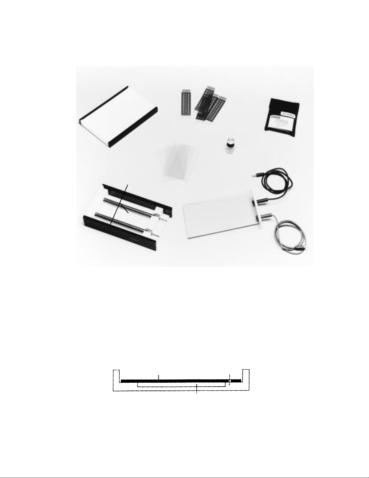
1.4 Model 111 Mini IEF Cell Components
Fig. 1.1. Model 111 Mini IEF Cell. Outer chamber (1), sliding, interlocking lid with power cables (2), graphite
electrodes (3), casting tray (4), glass plates (5), sample templates (6), gel support film (7), and 5 ml Bio-Lyte
3/10 ampholyte (8).
1.5 Capillary Thin Layer Gel Casting Tray
The Capillary Thin Layer Gel Casting Tray provides the fastest and easiest method for casting
electrofocusing gels.
The casting tray consists of an acrylic plate with precisely defined spacers of 0.4 mm
thickness as shown in Figure 1.2. The acrylic surface imparts a slight inhibitory effect on
acrylamide polymerization, eliminating sticking and tearing of the gel.
Fig. 1.2. Casting tray.
3
4
6
7
8
5
2
3
1
Glass plate
Gel
Spacer rails
Page 8

Section 2
Introduction to Isoelectric Focusing
2.1 The Electrofocusing Principle
Conventional electrophoresis separates proteins and other charged molecules by
electrophoretically-driven migration through a sieving matrix that is buffered at a constant pH.
Each component of the mixture assumes its own characteristic velocity based on molecular size
and surface charge. This velocity is constant throughout the electrophoresis experiment and is
counteracted by diffusion, which tends to broaden the bands. There is no tendency toward
equilibrium in conventional electrophoresis, and the protein bands will run off the gel if the
electrical field is not interrupted.
On the other hand, electrofocusing separates proteins on the basis of surface charge alone as a
function of pH. The separation is done in a non-sieving medium (sucrose density gradient,
agarose, or polyacrylamide gel) in the presence of carrier ampholytes, which establish a pH
gradient increasing from the anode to the cathode. Since a protein contains both positive (amines)
and negative (carboxyl) charge-bearing groups, the net charge of the protein will vary as a
function of pH.
A pH gradient is established concomitantly with protein separation. As the protein migrates
into an acidic region of the gel, it will gain positive charge via protonation of the carboxylic and
amino groups. At some point, the overall positive charge will cause the protein to migrate away
from the anode (+) to a more basic region of the gel. As the protein enters a more basic
environment, it will lose positive charge and gain negative charge, via ammonium and carboxylic
acid group deprotonation, and consequently, will migrate away from the cathode (-). Eventually,
the protein reaches a position in the pH gradient where its net charge is zero (defined as its pI or
isoelectric point). At that point, the electrophoretic mobility is zero. Migration will cease, and a
concentration equilibrium of the focused protein is established.
2.2 Carrier Ampholytes
Carrier ampholytes are complex mixtures of amphoteric buffers that form a smooth pH
gradient in an applied electrical field. During electrofocusing, these buffers stack according to
their individual pIs across the gel, producing a linear gradient. In order for the gradient to appear
smooth and continuous, a large number of these buffering components must be present. This is
also a requirement for separating a complex mixture of proteins.
Bio-Lyte ampholytes are derivatized low-molecular weight amines that are electrophoretically
separated and reblended to give smooth and reproducible gradients. Narrow range Bio-Lyte
ampholytes are produced and tested so that, under normal circumstances, no additional blending
or fortification will be necessary to achieve the desired shallow gradient.
4
Page 9

2.3 Choice of Support Matrix
The electrofocusing process must be stabilized against convection and, to a lesser extent,
diffusion, by a support matrix. This can be anything from a liquid column stabilized by a sucrose
density gradient to a gel cast from agarose or polyacrylamide. The principal criteria for a good
support matrix are that it should be relatively non-sieving so that molecular size is not a factor in
protein mobility, and that it must be free of charged groups which would give rise to internal fluid
flow and distortion of the pH gradient. A complete discussion of electrofocusing matrices is given
in Reference 1.
For analytical work, both agarose and polyacrylamide gels provide good supports for
electrofocusing. Agarose has the advantage of very large pore structures (as large as 500 nm),
making it an ideal non-sieving medium; however, it suffers from varying degrees of residual
negative charge from sulfate groups. For this reason, only agarose proven for electrofocusing
applications should be used (Bio-Rad’s Zero -MrAgarose, catalog number 162-0022). Agarose
concentrations may vary between 0.5 and 1.25%. Proteins as large as 50 x 106daltons have been
successfully electrofocused in agarose.
Section 3
Polyacrylamide Gel Isoelectric Focusing
3.1 Considerations in Matrix Preparation
Because they are prepared from monomers, polyacrylamide gels can be tailored to meet
particular separations requirements. The most common gel composition for horizontal
electrofocusing is T = 5%, C = 3%, where:
g acrylamide + g crosslinker
total solution volume in ml
g crosslinker
g acrylamide + g crosslinker
This formulation will give a suitable non-sieving gel for proteins up to 106daltons, that is still
rigid enough to handle conveniently. A slightly stronger gel of T=5%, C = 4% may be used for
protein samples under 200,000 daltons.
The choice of a catalyst is extremely important in electrofocusing, since any residual ions will
affect the final attainable voltage, and can lead to overheating and gross distortions in the gel. For
this reason a three-phase catalyst system of ammonium persulfate, riboflavin-5'-phosphate, and
TEMED is recommended. This system, catalyzed by light, will give reproducible polymerization
with a minimum of ionic contamination.
The formation of polyacrylamide gels has been extensively studied, and a detailed discussion
of practical considerations is available in Bio-Rad’s bulletin 1156.
5
x 100
%C =
x 100
%T =
Page 10

3.2 Stock Solutions for Polyacrylamide IEF Gels
Always use high quality distilled or deionized water to prepare stock solutions for
electrofocusing.
1. Monomer concentrate (T=25%, C=3%)
24.25% (w/v) acrylamide
0.75% (w/v) bis (N, N’-Methylene-bis-acrylamide)
Dissolve 24.25 g acrylamide and 0.75 g bis in water, bring to a final volume of 100 ml, and
filter through a 0.45 µm filter. Store protected from light at 4 °C. This solution may be stored
up to 1 month.
2. 0.1% (w/v) riboflavin-5'-phosphate (FMN)
50 mg riboflavin-5'-phosphate
50 ml water
This solution may be stored up to 1 month at 4 °C protected from light.
3. 10% (w/v) ammonium persulfate
100 mg ammonium persulfate
1 ml water
Prepare fresh daily. Make sure that the ammonium persulfate is completely dissolved before
using.
4. 25% glycerol (w/v)
Add 25 g glycerol to 50 ml H2O. Dilute to 100 ml with H20.
5. TEMED (N,N’-tetramethylene-ethylenediamine)
Use TEMED neat from the bottle. Use only pure, distilled TEMED. Store cool, dry, and
protected from light.
3.3 Reagents for Polyacrylamide Electrofocusing Gels
The following volumes will produce sufficient reagent for two 125 x 65 x 0.4 mm gels:
Monomer-ampholyte solution
H2O 5.5 ml
Monomer concentrate (25% T, 3% C) 2.0 ml
25% (w/v) glycerol 2.0 ml
*Ampholyte 0.5 ml
Catalyst solutions
10% (w/v) ammonium persulfate 15 µl
0.1% (w/v) FMN 50 µl
TEMED (neat) 3 µl
*Volume required for 40% ampholyte solutions (Bio-Lyte 3/10, 4/6, 5/7, 6/8, 7/9 ampholytes).
For 20% ampholyte (Bio-Lyte 3/5, 8/10 ampholytes) add 1 ml ampholyte and reduce H2O
volume to 5.0 ml.
6
Page 11

Note: The selection of appropriate ampholyte is determined by the pH range required for a
particular separation. Bio-Lyte ampholytes are specifically blended to produce a linear
gradient within the stated range and no further blending is generally needed. Particular
separations, however, may require a combination of two or more ampholytes to achieve a
desired result.
3.4 Use of Gel Support Film for Polyacrylamide
1. Remove a sheet(s) of Gel Support Film for Polyacrylamide (catalog number 170-2983) from
the package, and then reseal the package. Polyacrylamide gel support film is sensitive to light
over prolonged periods and must be kept sealed in the package until use. After the gel has
adhered to the support film, the film is no longer light sensitive.
2. Polyacrylamide gel support film has two surfaces, a treated (hydrophilic) side which the
acrylamide adheres to, and a hydrophobic surface. The sheets are packed with printed
interleaf paper which protects the treated surface. All sheets are packed treated side up. A
drop of water will bead on the hydrophobic surface and spread on the hydrophilic surface.
3. Pipet a few drops of water onto the clean glass plate.
4. Place the hydrophobic side of the gel support film against the plate.
5. Roll the gel support film flat with a test tube or similar object to force out excess water and air
bubbles.
6. Carefully wipe or blot off any excess liquid at the edges. The gel support film is now ready for
use, and should be used as soon as possible.
Note: Basic ampholytes (pH > 8.0) have been found to interfere with gel adhesion to the
polyacrylamide support film. Increasing the concentration of ammonium persulfate to 0.7
mg/ml in the final acrylamide gel solution (add 70 µl of 10% ammonium persulfate per 10 ml
solution) should alleviate the problem. Adhesion may also be affected by prolonged soaking
in acid solutions, such as in staining and destaining. Do not soak longer than absolutely
necessary to achieve the desired result.
7
Page 12

3.5 Casting Polyacrylamide Gels
Important: The Glass Plates and the casting tray must be clean and dry. Do not use organic
solvents, abrasive cleaners, or hot water on the casting tray. Clean the Glass Plates with soap
and water and rinse with deionized water followed by ethanol. Wipe the plates dry with lintfree paper.
1. With the gel support film facing down, place the Glass Plate(s) on the casting tray so that it
rests on the spacer bars.
2. Prepare the monomer-ampholyte solution (see Section 3.3). Degas the solution for 5 minutes
under vacuum. Do not degas longer, as a slight amount of O2is required to catalyze
riboflavin-5-phosphate.
4. Prepare the catalyst solutions.
Note: Always use freshly prepared persulfate solutions
5. Add the catalyst solutions to the degassed monomer and swirl gently.
Caution: Do not mouth pipet acrylamide solutions. Wear gloves. Acrylamide is a neurotoxin!
6. Pipet the solution between the glass plate and the casting tray as shown in Figure 3.1.
a. Hold the pipet at a 45° angle and clear the air bubble from the tip.
b. Start the monomer flow at one end of the glass plate and slowly move the pipet to the
other spacer.
c. When a liquid front is established across the plate, slowly add the remaining monomer
from the midpoint of the plate.
d. Control the flow rate to prevent air bubbles. If a bubble is trapped, remove it by sliding the
plate sideways until the bubble is at the edge.
Fig. 3.1. Injecting monomer/ampholyte solution in casting tray.
8
a. Clear bubble from end of pipet. b. Start solution at one corner of
plate and move it along the edge to form a front. Be sure the
solution contacts both the plate and tray. Avoid trapping air
bubbles by releasing the solution slowly.
c. Continue to inject solution, keeping the
front fairly even to avoid forming bubbles.
b
a
Remove
this bubble
Page 13

7. Position a photopolymerization light (such as Bio-Rad’s catalog number 170-4220 or 170-
4242. See Section 9.2) over the tray. Any fluorescent desk lamp is a suitable alternative.
8. Irradiate the solution for 45 minutes.
9. To lift the gel from the casting tray:
a. Lift one corner with a flat spatula inserted between the gel and the casting tray (see
Figure 3.2).
b. When air appears under the gel, gently lift the plate free from the casting tray.
10. Flip the plate, glass side down, onto the casting tray and further irradiate for 15 minutes to
eliminate unpolymerized monomer on the gel surface.
Fig. 3.2. Lifting the gel from the casting tray.
3.6 Sample Preparation
Protein samples for isoelectric focusing must be free of precipitates. Substantially salt-free
samples in typical biochemical buffers are usually tolerated, though better results can be obtained
with solutions in deionized water, 2% ampholytes, or 1% glycine. Suitable protein solutions may
be prepared by dialysis, or gel filtration with Bio Spin®6 chromatography columns (catalog
number 732-6000 (10) or 732-6002 (25)) or with Bio-Gel®P-6DG desalting gel (catalog number
150-0738).
Many samples will require the use of urea, ethylene glycol, non-ionic detergents (i.e. Triton
®
X-100 detergent, NP-40, Lubrol®WX detergent, or octylglucopyranoside), or zwitterionic
detergents (CHAPS, CHAPSO). Even in the presence of detergents, some samples may resist
solubility due to salt requirements. Only if high salt is an absolute requirement should it be
present in a sample, and even then, substantial distortions and anomalies can be expected.
9
Page 14

3.7 Sample Application
Sample application is most conveniently accomplished using the included Sample Templates.
1. Place the template on top of the polymerized gel. The colored portion of the template should
coincide with the longer dimension of the gel. The application position for the sample varies
(see Section 3.8) but allow 1 cm at both the top and bottom of the gel for the gel to contact the
electrodes.
2. Apply samples using a pipettor capable of delivering between 0.5 µl and 2 µl. Volumes above
2 µl are not generally recommended for use with the sample template.
3. Allow samples to diffuse into the gel for 5 minutes.
4. Carefully remove the template from the gel.
Note: For larger samples, one may custom-form application strips from filter paper or use
Bio-Rad’s Sample Application Pieces (catalog number 170-4257). Apply the sample to the
filter paper and then place the filter paper at the point of application on the gel. Allow the
sample to diffuse into the gel for 5 minutes. The disadvantage of this method is that some
proteins may not be completely eluted from the strip to the gel.
3.8 Position of Application
There are no fixed rules regarding the positioning of the sample on the gel. Samples should
not, in general, be applied to areas where protein bands are expected to focus. To protect the
proteins from extreme pH exposure, the samples should not be applied closer than 1 cm from
either electrode. The best strategy for a new protein is to make three points of application, one at
each end and one near the middle of the gel, and observe the resulting focusing pattern.
Section 4
Running the Gel
4.1 Set Up Procedure
1. Slide the lid of the Model 111 Mini IEF Cell toward the electrode plugs to remove it.
2. Remove the Graphite Electrodes from the cell and rinse them with distilled water to remove
traces of acrylamide from the previous run. The electrodes may be gently wiped with a
laboratory tissue if necessary. Place the electrodes back into the cell.
3. Lightly moisten the graphite electrodes with water. Turn the gel with the adsorbed samples
upside-down and place it directly on top of the electrodes. Position the gel carefully the first
time, as re-positioning may damage the gel surface. Do not remove the glass plate from the
gel/gel support backing because its weight insures good contact between the gel and the
electrodes.
4. Carefully slide the lid back onto the Model 111 Mini IEF Cell. Plug the power cables of the
cell into a power supply able to generate 500 V constant voltage. The cell is now ready to
separate samples.
10
Page 15

4.2 Run Conditions
1. Focusing is carried out under constant voltage conditions in a stepped fashion. Begin focusing
at 100 V for 15 minutes.
2. Increase voltage to 200 V for 15 minutes.
3. Finally, increase the voltage to 450 V for an additional 60 minutes.
Note: Step increases of voltage are necessary to prevent overheating and subsequent
dehydration of the gel. Failure to follow this procedure will result in poor resolution. One
advantage of using Bio-Rad’s PowerPac 3000 or Model 1000/500 power supply is that either
power supply can be programmed to carry out this stepped increase in voltage automatically.
4. Typical running conditions for various ranges of Bio-Lyte ampholytes in the Model 111 Mini
IEF Cell are shown in Table 4.1. Any gross variation from these values could indicate
problems associated with polymerization, buffer preparation, etc.
Table 4.1 Typical Running Conditions
Bio-Lyte pH Current/Power Current/Power Current/Power
Range at 100 V at 200 V at 450 V
3-10 5-6 mA/0.5-0.6 W 5-6 mA/1 W 4 mA/2 W
4-6 3 mA/0.3 W 3-4 mA/0.6-0.8 W 4-5 mA/2 W
5-7 3 mA/0.3 W 3-4 mA/0.6-0.8 W 4-5 mA/2 W
6-8 3 mA/0.3 W 3-4 mA/0.6-0.8 W 4-5 mA/2 W
7-9 3 mA/0.3 W 3-4 mA/0.6-0.8 W 4-5 mA/2 W
8-10 10 mA/1 W 20 mA/4 W 4 mA/2 W
5. A good way to monitor the progress of an isoelectric focusing experiment is to observe the
migration of visible marker proteins of known pI to their isoelectric points. The IEF Standards
(catalog number 161-0310) provide eight natural proteins, including four visible proteins that
are clearly discernable during an IEF run. These markers are useful with all non-denaturing
IEF buffer systems.
6. As the focusing nears completion, the current will decrease from the values listed in the 450 V
column. This is a general indication that the focusing is near completion.
Note: The Model 1000/500 Power Supply measures current to the microampere range. This
expanded monitoring of the changes in current allows better estimation of the time the current
stabilizes and the experiment is finished.
11
Page 16

Section 5
Sample Detection and Gel Storage
5.1 Removing the Gel
1. After electrofocusing is complete, turn off the power supply and unplug the power cables.
2. Slide the protective lid from the cell and remove the gel from the electrodes. At this point
separate the gel/gel support film from the glass plate.
3. Remove the Graphite Electrodes and clean with water and a tissue. Rinse the chamber with
distilled water. Put the electrodes back into the cell to prevent damage during storage.
Cleaning the electrodes immediately after the run will increase their life span.
5.2 Band Detection
In general, proteins are detected by fixing and staining. If the proteins are not fixed
immediately, the high resolving power of electrofocusing can be lost to diffusion. Small proteins
and proteins with basic pIs are particularly difficult to fix. Autoradiography, biological activity,
group specific staining, and immunological methods are a few examples of alternative detection
techniques currently being used.
This section gives two recommended staining procedures for electrofocusing using Coomassie
blue R-250, which has a detection limit for most proteins in µg quantities. Either method produces
acceptable results, however, Method B is significantly easier to use and, in some cases, will
produce a sharper pattern. For more sensitive detection down to ng levels of protein, the Bio-Rad
Silver Stain (catalog number 161-0443) is recommended.
The cupric sulfate in the staining and destaining solutions effectively eliminates any
background staining due to the presence of ampholytes.
Fixing and Staining
Method A Method B
Fixative: Fixative:
4% sulfosalicylic acid Not necessary
12.5% trichloroacetic acid
30% methanol
Immerse gels in this solution for 30 minutes.
Method A Method B
Stain: Stain:
27% isopropanol or ethanol Same as Method A, but with
10% acetic acid 0.05% crocein scarlet
0.04% Coomassie brilliant blue R-250
0.5% CuSO
4
(0.05% crocein scarlet optional)
Dissolve the CuSO4in water before adding the alcohol.
Either dissolve the dye in alcohol or add it to the solution
at the end.
Immerse the gel in the stain for approximately 1-2 hours.
12
Crocein scarlet, a highly soluble
dye which rapidly binds to
protein, is included to assure rapid
fixation of the bands. This
procedure is inadequate if
Coomassie brilliant blue R-250 is
used alone.
Page 17

5.3 Destaining (For both Method A and Method B)
First destaining solution:
12% isopropanol or ethanol
7% acetic acid
0.5% CuSO
4
Dissolve the cupric sulfate in water before adding the alcohol. Immerse the gel in two or three
500 ml changes of this solution until the background is nearly clear. Gentle agitation and
slight heating will speed the destaining process.
Second destaining solution:
25% isopropanol or ethanol
7% acetic acid
Immerse the gel in this solution to remove the last traces of stain and CuS04.
Note: Prolonged soaking of gels with gel support film backings in acidic solutions may cause
the gel to separate from the backing. Staining and destaining steps should be no longer than 3-4
hours.
5.4 Other Detection Methods
1. Coomassie Blue G-250 “Quick Stain”
This technique is nearly as sensitive as Coomassie blue R-250 staining, but requires no
destaining and will not stain ampholytes. It cannot be used in the presence of detergents,
except urea.
3.5% perchloric acid
0.025% Coomassie blue G-250
Immerse gels in this solution for 1 hour. Place in 7% (v/v) acetic acid for intensification and
preservation.
2. Ultrasensitive Silver Stain
Bio-Rad’s Silver Stain (catalog number 161-0443) is 10 to 50 times more sensitive than
Coomassie blue (see Bulletin 1089) and is compatible with both supported and unsupported
gels.
5.5 Gel Drying and Preservation
Place the destained gel in a dust free area with good ventilation (a fume hood is excellent for
this purpose) and allow the gel to dry overnight at room temperature. Alternatively, the gel can be
carefully dried with a heat gun on a low heat setting. Dried gels can be stored in plastic
photograph holders or taped directly into notebooks (gel side down).
13
Page 18

Section 6
Agarose Gel Electrofocusing
6.1 Introduction
Agarose isoelectric focusing separates large proteins and antibodies that cannot be readily
characterized on polyacrylamide IEF gels due to polyacrylamide’s smaller pore sizes. Molecules
greater than 200,000 daltons can easily be separated on a 1% agarose gel.
The agarose gels are formed within minutes by simply heating the agarose mixture and
pouring it into the casting tray much the same way as casting acrylamide gels. Sorbitol and
glycerol are incorporated into the agarose gel to increase gel viscosity and to counteract
electroendosmosis (EEO), a major cause of sample smearing. EEO is the cathodic flow of water
in the neutral and alkaline parts of the gel caused by the low concentration of fixed charge
carboxyl groups on the gel matrix. These carboxyl groups are not charged at pH 3.5 or lower, but
acquire their full charges at pH 5.5 and higher. As a consequence, gel shrinkage occurs at the pK
of the carboxyl groups, resulting in “flooding” of water and solutes at the alkaline portion of the
gel. EEO decreases when gel viscosity increases.
The procedure for agarose isoelectric focusing is simple, consisting of the following seven
steps. Each of these steps is described in detail in Sections 6.3 through 6.6.
1. Cast the agarose gel.
2. Dehydrate the gel to remove excess liquid.
3. Focus the gel for 90 minutes.
4. Immerse the gel in fixative solution.
5. Immerse the gel in ethanol to remove background.
6. Immerse the gel in stain.
7. Destain the gel.
6.2 Preparing Agarose Gels
Agarose IEF gel contains:
1% agarose, zero-M
r
2% ampholytes
5% sorbitol
10% glycerol
1. Add 0.5 grams of Bio-Rad’s Zero-MrAgarose and 2.5 grams of sorbitol to 20 ml of 25%
glycerol and 10 ml of distilled water. Place a stir bar into the flask and immerse the flask in a
beaker of water. Heat the water to boiling (100 °C) and stir to dissolve the components (30
minutes).
2. Place the casting tray into a prewarmed 55 °C oven and allow it to equilibrate. The tray should
remain in the oven until just prior to pouring the gels.
3. Turn off heat and add ampholytes while stirring the agarose mixture (2.5 ml of 40%
ampholytes or 5 ml of 20% ampholytes). Add more hot (100 °C) distilled water for a final
volume of 50 ml.
4. Allow solution to cool to about 55 °C before pouring agarose. A hot water bath set to 55 °C is
optimal.
14
Page 19

Note: Do not heat the casting tray to more than 55 °C. Extended heating above this
temperature may cause the spacers to separate from the casting tray and may cause the tray to
warp.
5. Remove a sheet of Gel Support Film for Agarose (catalog number 170-2984) from the
package.
6. Test for hydrophobic side by placing a drop of water on the film. The water beads on the
hydrophobic side, and spreads on the hydrophilic side.
7. Pipet a few drops of water onto the glass plate.
8. Place the hydrophobic side of the Gel Support Film for Agarose against the plate.
9. Roll the Gel Support Film for Agarose flat with a test tube or similar object to force out
excess water and air bubbles.
10. Remove the casting tray from the oven and place it on a level surface.
11. Heat a glass pipet with hot water and pipet 4 ml of the warm agarose solution in a bead across
the width of the casting tray.
12. Carefully lower the Glass Plate (with the gel support film side down) onto the agarose. Allow
the agarose to spread completely underneath the glass plate. Some agarose may extend outside
the glass plate.
13. If there are any areas under the Glass Plate not filled with agarose, simply tilt the casting tray
and the agarose should fill in these areas quickly.
14. If there are any air bubbles trapped, tapping on the Glass Plate should remove them.
15. The gel will solidify within 10-15 minutes. At this point, let the gel “age” at 4 °C (refrigerate)
for a minimum of 4 hours, preferably overnight. The gels may be left in the casting tray.
Simply cover the tray with plastic wrap to prevent dehydration of the gel.
16. To lift the gel from the casting tray:
a. Lift one corner with a flat spatula inserted between the gel and the casting tray
(Figure 6.1).
Fig. 6.1. Loosening the plate.
15
Page 20

6.3 Sample Preparation
Protein samples for isoelectric focusing must be free of precipitates. Substantially salt-free
samples in typical biochemical buffers are usually tolerated, though better results can be obtained
with solutions in deionized water, 2% ampholytes, or 1% glycine. Suitable protein solutions may
be prepared by dialysis, or gel filtration with Bio-Gel P-6DG desalting gel (catalog number 150-
0738).
A convenient technique for preparing small samples is to load a small amount of hydrated
Bio-Gel P-6DG gel into a 0.5 ml plastic microcentrifuge tube with a small hole in the bottom.
Load the sample on top of the gel and place this tube into a 1.5 ml plastic microcentrifuge tube.
Spin for 5 seconds in a microcentrifuge. The sample will be adequately desalted for isoelectric
focusing, and can be isolated from the bottom of the larger tube.
Many samples will require the use of urea, ethylene glycol, non-ionic detergents (i.e. Triton
X-100, NP-40, Lubrol WX, or octylglucopyranoside), or zwitterionic detergents (CHAPS,
CHAPSO). Even in the presence of detergents, some samples may resist solubility due to salt
requirements. Only if high salt is an absolute requirement should it be present in a sample, and
even then, substantial distortions and anomalies can be expected.
6.4 Sample Application
Sample application is most conveniently accomplished using the included Sample Templates.
1. Place the template on top of the polymerized gel. The colored portion of the template should
coincide with the longer dimension of the gel. The application position for the sample varies
(see Section 6.5) but one should allow 1 cm at both the top and bottom of the gel where the
gel will contact the electrodes.
2. Apply samples using a pipettor capable of delivering between 0.5 µl and 2 µl. Volumes above
2 µl are not generally recommended when using the sample template.
3. Allow samples to diffuse into the gel for 5 minutes.
4. Carefully remove the template from the gel.
Note: For larger amounts and sizes of samples, one may custom-form application strips from
filter paper, or use Bio-Rad’s Sample Application Pieces (catalog number 170-4257). Apply
the sample to the filter paper and then place the filter paper at the point of application on the
gel. Allow the sample to diffuse into the gel for 5 minutes. The disadvantage of this method is
that some proteins may not be completely eluted from the strip to the gel.
6.5 Position of Application
There are no fixed rules regarding the positioning of the sample on the gel. Samples should
not, in general, be applied in areas where protein bands are expected to focus. To protect the
proteins from extreme pH exposure, the samples should not be applied closer than 1 cm from
either electrode. The best strategy for a new protein is to make three points of application, one at
each end and one near the middle of the gel, and observe the resulting focusing pattern.
6.6 Set Up Procedure
1. Slide the lid of the Model 111 Mini IEF Cell toward the electrode plugs to remove it.
2. Remove the Graphite Electrodes from the cell and rinse them with distilled water to remove
traces of agarose from the previous run. The electrodes may be gently wiped with a laboratory
tissue if necessary. Place the electrodes back into the cell.
16
Page 21

3. Lightly moisten the Graphite Electrodes with water. Turn the gel with the adsorbed samples
upside down and place it directly on top of the electrodes. Position the gel carefully the first
time as re-positioning may damage the gel surface. Do not remove the glass plate from the
gel/gel support backing because its weight insures good contact between the gel and the
electrodes.
4. Carefully slide the lid back onto the Model 111 Mini IEF Cell. Plug the power cab cell into a
power supply able to generate 500 V constant voltage. The cell is now ready to separate
samples.
6.7 Run Conditions
1. Focusing is carried out under constant voltage conditions in a stepped fashion. Begin focusing
at 100 V for 15 minutes.
2. Increase voltage to 200 V for 15 minutes.
3. Finally, increase the voltage to 450 V for an additional 60 minutes.
Note: Step increases of voltage are necessary to prevent overheating and
subsequent dehydration of the gel. Failure to follow this procedure will result in poor
resolution.
4. A good way to monitor the progress of an isoelectric focusing experiment is to observe the
migration of visible marker proteins of known pI to their isoelectric points. The IEF Standards
(catalog number 161-0310) provide eight natural proteins, including four visible proteins that
are clearly discernable during an IEF run. These markers are useful with all non-denaturing
IEF buffer systems.
5. As the focusing nears completion, the current will decrease substantially. This is a general
indication that the focusing is near completion.
6.8 Sample Detection
1. After the focusing is complete, turn off the power supply and disconnect the power cables
from it.
2. Slide the lid off the Model 111 Mini IEF Cell and carefully remove the gel from the Graphite
Electrodes. Rinse the electrodes with water and wipe them gently with a tissue. Replace the
electrodes in the cell.
3. Place the gel/gel support film (Glass Plate is removed at this point) into fixative solution for
15 minutes.
Fixative Solution
30% methanol
5% trichloroacetic acid (TCA)
3.5% sulfosalicylic acid (SSA)
4. To insure a clear gel background, take the agarose gel directly from the fixative solution to a
95% ethanol bath. Immerse the gel in ethanol for 30 minutes with occasional swirling.
5. After the ethanol wash, place the gels on a level surface. Soak one piece of filter paper in
ethanol and place it on top of the gel. Then place additional dry filter paper (8-10 sheets) or
folded paper towels on top of the ethanol-soaked paper. Press the gel with a 1 kg weight for
30 minutes.
6. After pressing, dry the gel completely with an air blow dryer or under a laboratory hood’s fan.
17
Page 22

7. Autoradiography, biological activity, group specific staining, and immunological techniques
are just a few examples of many detection techniques currently used. The typical IEF stain is
Coomassie brilliant blue R-250.
Stain
0.2% Coomassie brilliant blue R-250
28% isopropanol or ethanol
14% acetic acid
Filter the stain before use. The gel should be stained a minimum of 30 minutes at room
temperature.
8. Destaining the gels should take only 30 minutes at room temperature.
Destain Solution
28% isopropanol or ethanol
14% acetic acid
9. Air dry the gel plate.
18
Page 23

Section 7
Troubleshooting
7.1 General Troubleshooting
Problem Cause Solution
19
1. Excessive pooling
of water at the
cathode(-)
Agarose only.
2. Distortion in
gradient where
sample is applied.
3. Sample streaking.
4. pH gradient does
not cover
expected range.
a. Poor quality agarose.
b. Gel has not been sufficiently
blotted dry sufficiently
blotted dry prior to run.
a. Too much salt in sample.
b. Sample is applied too
near the anode.
c. Sample load excessive.
d. Sample precipitation.
a. Particles in sample.
b. Sample absorbed onto
applicator.
c. Precipitation at point of
application.
a. Focused too long or use of
excessive voltage.
b. Basic gels stored too
long.
c. Poor quality acrylamide
and Bis.
d. Old acrylamide and
Bis stock solutions.
a. Use Bio-Rad’s Zero - MrAgrose
only
b. Blot all excess liquid from gel prior
to run.
a. Dialyze against ampholyte1%
glycine or water, or desalt with
Bio-Gel P-2 or P-6DG gel.
b. Apply elsewhere on plate,
minimum of 1 cm from anode.
c. Dilute sample.
d. Spin to remove insolubles or use
detergents.
a. Centrifuge sample before
application.
b. Change application method.
c. Try a different position.Use
additives (1% glycine,urea, nonionic detergents,amphoteric
detergents).
a. At recommended constant voltage,
proteins should be focused within
1.5 hours.
b. Use basic gels (pH>7)
immediately to prevent hydrolysis
of acrylamide to acrylic acid,
which causes
electroendosmosis.
c. Use highest quality acrylamide
and Bis to avoid polymerizing
acrylic acid into into the gel.
d. Prolonged storage of acrylamide
and Bis leads to acrylic acid
formation.
Page 24

Problem Cause Solution
e. Ampholyte contamination e. Check ampholyte for bacterial
or deterioration contamination.
Solution will look cloudy.
Inspect under a microscope.
Check date of receipt and
storage conditions.
5. No current/power at a. Poor gel/electrode a. Lightly moisten Graphite
recommended voltage. contact. Electrode before applying
gel.
b. Electrodes dirty. b. Remove residue with
tissue and water. Always
clean electrodes after run.
c. Poor electrical contact in c. Make sure lid is pushed on
unit. completely and electrodes
are properly seated.
7.2 Casting Troubleshooting: Polyacrylamide Gels
Problem Cause Solution
1. Gel does not adhere to a. Incomplete a. Use only high purity
backing; sticks to casting polymerization. acrylamide and Bis. Inferior
tray. monomers are difficult to
polymerize.
Store solutions in amber
bottles at 4 °C for no more
than 4 weeks.
Make fresh catalyst solutions
daily.
Use higher catalyst levels
with ampholytes other than
Bio-Lyte ampholytes.
Degas longer if gels are
polymerized exclusively with
APS or TEMED. Degas for
shorter time if riboflavin is
one of the catalysts.
Primary amine ampholytes,
especially basic species,
contribute to short chain
polymer formation like the
polymerization seen when
high levels of TEMED are
used. Reduce ampholyte
concentration to 1%, do not
degas or add polymerization
inhibitor. Only use TEMED
when combined with APS
and riboflavin-5'-PO4.
20
Page 25

Problem Cause Solution
b. Polymerization time b. Optimize polymerization time
is too long, causing by placing excess solution in
gel to dry onto plastic a 12 x 75 mm glass test tube
at the edges of the plate. and putting the test tube under
Especially true with gels the polymerization light.
polymerized with APS. Remove plate 15 minutes
after test tube solution gels.
c. Incorrect procedure used c. Do not slide plate sideways
to lift plate from casting before removing it. Do not
tray. pry the plate up with fingers.
Twist the spatula to raise the
plate edge nearest the
spacer. This allows air to
penetrate between the gel
and the plastic without
forming a vacuum.
d. Dirty glass plates and d. Wash plates and casting tray
casting tray. with Bio-Rad’s Cleaning
Concentrate, and rinse them
thoroughly with deionized or
distilled water.
e. Use of wrong side of gel e. Gels must be cast on the
support film. treated (hydrophilic) side of
gel support film.
f. Use of Bio-Lyte 8/10 f. Adhesion is decreased when
ampholyte. using ampholytes with a pH ≥
8.0. Increase ammonium
persulfate to 0.7 mg/ml (7 µl
of 10% APS stock per ml
solution) and TEMED at
1 µl/ml.
g. Gel support film exposed g. Always keep gel support film
to light for extended sealed in its light-proof
periods. package. Store at room
temperature.
7.3 Casting Troubleshooting: Agarose Gels
Problem Cause Solution
1. Gel does not adhere to a. Use of incorrect side of a Always cast gels on treated
gel support film; sticks to gel support film. (hydrophilic) surface of gel
casting tray. support film.
b. Dirty glass plates and b. Wash plates and casting tray
casting tray. with Bio-Rad’s Cleaning
Concentrate, then rinse
thoroughly with deionized or
distilled water.
c. Casting tray not c. Allow 15-30 minutes for
equilibrated to 55 °C. casting tray to equilibrate to
55 °C in oven.
d. Agarose solution too hot d. For maximum adhesion, cast
or too cold. agarose solutions at 55 °C.
21
Page 26

Section 8
References
1. Righetti, P.G., Isoelectric Focusing: Theory, Methodology and Applications, Elsevier Biomedical Press,
Amsterdam (1983).
2. Righetti, P.G. and Drysdale, J.W., Isoelectric Focusing, North-Holland Publishing Company, Amsterdam
(1976).
3. Radola, B.J. Modern Methods in Protein Chemistry, 21, Walter de Gruyter & Co., New York (1983).
Triton®is a registered trademark of Rohm and Haas.
Lubrol®is a registered trademark of I.C.I Organics, Inc.
22
Page 27

Section 9
Equipment and Accessories
9.1 Equipment
Catalog
Number Description
170-2975 Model 111 Mini IEF Cell, includes outer chamber and interlocking lid;
2 Graphite Electrodes; gel casting tray; 5 Glass Plates; Gel Support Film for
Acrylamide, 50 sheets; 5 Sample Templates; 5 ml of Bio-Lyte 3/10 ampholyte;
and instructions
170-2976 Model 111 Mini IEF Cell, same as above, without casting tray
9.2 Accessories
Catalog
Number Description
170-2980 Graphite Electrodes, 2
170-2981 Capillary Thin Layer Gel Casting Tray
170-2982 Glass Plates, 125 x 65 x 1.5 mm, 5
170-2985 Sample Templates, 5
170-4220 Photopolymerization Light, 110 V
170-4242 Photopolymerization Light, 220 V
170-4257 Sample Application Filter Paper, 200 pieces
9.3 Gel Support Film
Catalog
Number Description
170-2983 Gel Support Film for Acrylamide, 125 x 65 mm, 50 sheets
170-2984 Gel Support Film for Agarose, 125 x 65 mm, 50 sheets
9.4 Isoelectric Focusing Chemicals and Reagents
Catalog
Number Description
161-0310 IEF Standards, pI 4.6-9.6
161-0100 Acrylamide, 99.9%, 100 g
161-0101 Acrylamide, 99.9%, 500 g
161-0107 Acrylamide, 99.9%, 1 kg
161-0103 Acrylamide, 99.9%, 2 kg
161-0108 Acrylamide, 99.9%, 5 kg
161-0200 Bis (N,N’-Methylene-bis-acrylamide), 5 g
161-0201 Bis (N,N’-Methylene-bis-acrylamide), 50 g
161-0501 Riboflavin-5’-Phosphate, 10 g
161-0700 Ammonium Persulfate, 10 g
161-0800 TEMED, 5 ml
161-0801 TEMED, 50 ml
162-0022 Zero -mrAgarose, 10 g
23
Page 28

9.5 Bio-Lyte Ampholytes
Catalog
Number Description
163-1112 Bio-Lyte 3/10 Ampholyte, 40%, 10 ml
163-1132 Bio-Lyte 3/5 Ampholyte, 20%, 10 ml
163-1142 Bio-Lyte 4/6 Ampholyte, 40%, 10 ml
163-1152 Bio-Lyte 5/7 Ampholyte, 40%, 10 ml
163-1192 Bio-Lyte 5/8 Ampholyte, 40%, 10 ml
163-1162 Bio-Lyte 6/8 Ampholyte, 40%, 10 ml
163-1172 Bio-Lyte 7/9 Ampholyte, 40%, 10 ml
163-1182 Bio-Lyte 8/10 Ampholyte, 20%, 10 ml
163-1113 Bio-Lyte 3/10 Ampholyte, 40%, 25 ml
163-1143 Bio-Lyte 4/6 Ampholyte, 40%, 25 ml
163-1153 Bio-Lyte 5/7 Ampholyte, 40%, 25 ml
163-1193 Bio-Lyte 5/8 Ampholyte, 40%, 25 ml
163-1163 Bio-Lyte 6/8 Ampholyte, 40%, 25 ml
9.6 Stains
Catalog
Number Description
161-0400 Coomassie Blue R-250, 10 g
161-0406 Coomassie Blue G-250, 10 g
161-0417 Crocein Scarlet, 10 g
161-0443 Silver Stain Kit, includes: oxidizer concentrate, silver reagent concentrate,
and developer, enough to stain approximately 48 mini IEF gels
161- 0449 Silver Stain Plus Kit, includes: fixative enhanced concentrate, silver complex
solution, reduction moderator sloution, image development reagent,
development accelerator reagent, enough to stain approximately 40 mini IEF
gels
9.7 Sample Preperation
Catalog
Number Description
732-6000 Bio Spin 6 Chromatography Column, 10
732-6002 Bio-Spin 6 Chromatography Column, 25
9.8 Power Supplies
Catalog
Number Description
165-5056 PowerPac Power Supply, 100 VAC
165-5057 PowerPac Power Supply, 220 VAC
165-4710 Model 1000/500 Programmable Power Supply, 100/120 VAC, 50/60 Hz
165-4711 Model 1000/500 Programmable Power Supply, 220/240 VAC, 50/60 Hz
24
Page 29

Eastern Regional Office,
85A Marcus Dr., Melville, New York 11747 • Phone (516) 756-2575 • Fax (516) 756-2594
European Headquarters,
Bio-Rad Laboratories, Dreve du Sénéchal, 19, B-1180 Brussels • Phone 02 375 59 70 • Fax 02 374 61 62
Australia,
Bio-Rad Laboratories Pty Limited, Unit 11, 112-118 Talavera Rd P.O. Box 371, North Ryde, N.S.W. 2113 • Phone 02-805-5000 • Fax 02-805-1920
Austria,
Bio-Rad Laboratories Ges.m.b.H., Auhofstrasse 78D, A-1130 Wien • Phone 0222-877 89 01 • Fax 0222-876 56 29
Belgium,
Bio-Rad Laboratories S.A./N.V., Begoniastraat 5, B-9810 Nazareth Eke • Phone 091-85 55 11 • Fax 091-85 65 54
Canada,
Bio-Rad Laboratories (Canada) Ltd., 5149 Bradco Boulevard, Mississauga, Ontario L4W 2A6 • Phone (416) 624-0713 • Fax (416) 624-3019
China,
Bio-Rad Laboratories, Yanshan Hotel Office Tower, #1307, 138A Haidian Road, Beijing • Phone 2563146 • Fax 2564308
France,
Bio-Rad S.A., 94/96 rue Victor Hugo, B.P. 220, 94203 Ivry Sur Seine Cedex • Phone 01-49 60 68 34 • Fax 01-46 71 24 67
Germany,
Bio-Rad Laboratories GmbH, Heidemannstraße 164, Postfach 45 01 33, D-8000 München 45 • Phone 089-318 84-0 • Fax 089-318 84 100
Italy,
Bio-Rad Laboratories S.r.l.,Via Cellini, 18A, 20090 Segrate Milano • Phone 02-21609.1 • Fax 02-21609-399
Japan,
Nippon Bio-Rad Laboratories, K. K., Sumitomo Seimei Kachidoki Bldg 5-3-6 Kachidoki, Chuo-Ku, Tokyo 104 • Phone 03-3534-7515 • Fax 03-3534-8027
The Netherlands,
Bio-Rad Laboratories B. V., Fokkerstraat 10, 3905 KV Veenendaal • Phone 08385-40666 • Fax 08385-42216
New Zealand,
Bio-Rad Laboratories, Pty Ltd., P. O. Box 100-051, North Shore Mail Centre, Auckland 10 • Phone 09-443 3099 • Fax 09-443 3097
Pacific,
Bio-Rad Laboratories, Unit 1111, 11/F., New Kowloon Plaza, 38, Tai Kok Tsui Road, Tai Kok Tsui, Kowloon, Hong Kong • Phone 7893300 • Fax 7891257
Scandinavia,
Bio-Rad Laboratories, Kanalvägen 10C, 19461 Upplands Väsby, Sweden • Phone 46 (0) 8 590-73489 • Fax 46 (0) 8 590-71781
Spain,
Bio-Rad Laboratories, S. A. Avda Valdelaparra 3, Pol. Ind. Alcobendas, E-28100 Alcobendas, Madrid • Phone (91) 661 70 85 • Fax (91) 661 96 98
Switzerland,
Bio-Rad Laboratories AG, Kanalstrasse, 17, 8152 Glattbrugg • Phone 01-810 16 77 • Fax 01-810 19 33
United Kingdom,
Bio-Rad Laboratories Ltd., Bio-Rad House, Maylands Avenue, Hemel Hempstead, Herts HP2 7TD • Phone 0800 181134 • Fax 0442 259118
Life Science
Group
2000 Alfred Nobel Drive
Hercules, California 94547
Telephone (510) 741-1000
Fax: (510) 741-1060
Printed in USA
M1702975 Rev B
Bio-Rad
Laboratories
 Loading...