

Page 1
Model
Model version
Art. No.
Voltage
UF V
UF V 500
UFV500-230V
9020-0347, 9120-0347
230 V
UF V 700
UFV700-230V
9020-0348, 9120-0348
230 V
Operating Manual
Translation of the Original Operating Manual
ULTRA.Guard™
Ultra Low Temperature Freezers UF V (E3)
with RD4 Controller
BINDER GmbH
Address: Post office box 102, 78502 Tuttlingen, Germany Phone: +49 7462 2005 0
Fax: +49 7462 2005 100 Internet: http://www.binder-world.com
E-mail: info@binder-world.com Service Hotline: +49 7462 2005 555
Service Fax: +49 7462 2005 93 555 Service E-Mail: service@binder-world.com
Service Hotline USA: +1 866 885 9794 or +1 631 224 4340 x3
Service Hotline Asia Pacific: +852 390 705 04 or +852 390 705 03
Service Hotline Russia and CIS: +7 495 988 15 16
Version 09/2018 Art. No. 7001-0374
Page 2

Contents
1. SAFETY .................................................................................................................. 6
1.1 Legal considerations ........................................................................................................................... 6
1.2 Structure of the safety instructions ...................................................................................................... 6
1.2.1 Signal word panel ...................................................................................................................... 7
1.2.2 Safety alert symbol .................................................................................................................... 7
1.2.3 Pictograms ................................................................................................................................. 8
1.2.4 Word message panel structure ................................................................................................. 8
1.3 Localization / position of safety labels at the chamber ........................................................................ 9
1.4 Type plate .......................................................................................................................................... 10
1.5 General safety instructions on installing and operating the chamber ................................................ 11
1.6 Intended use ...................................................................................................................................... 13
1.7 Operating instructions ....................................................................................................................... 13
1.8 Measures to prevent accidents ......................................................................................................... 14
2. CHAMBER DESCRIPTION .................................................................................. 15
2.1 Chamber overview ............................................................................................................................ 17
2.2 Door lock and controller housing ....................................................................................................... 19
2.2.1 Operating the NumPad (option “Door access system”) ........................................................... 20
2.2.2 Operating the electromechanical door locking (option “Door access system”) ....................... 20
2.3 Main power switch ............................................................................................................................. 21
2.4 Chamber rear .................................................................................................................................... 22
2.5 Doors ................................................................................................................................................. 23
2.5.1 Outer door................................................................................................................................ 23
2.5.2 Compartment doors ................................................................................................................. 23
2.6 Drain well for condensate during defrosting (option) ......................................................................... 24
3. COMPLETENESS OF DELIVERY, TRANSPORTATION, STORAGE, AND
INSTALLATION .................................................................................................... 25
3.1 Unpacking, and checking equipment and completeness of delivery................................................. 25
3.2 Guidelines for safe lifting and transportation ..................................................................................... 26
3.2.1 Moving the freezer inside a building ........................................................................................ 26
3.2.2 Transport outside a building .................................................................................................... 27
3.3 Storage .............................................................................................................................................. 28
3.4 Location of installation and ambient conditions ................................................................................. 28
4. INSTALLATION AND CONNECTIONS ................................................................ 30
4.1 Operating instructions ....................................................................................................................... 30
4.2 Spacers for rear wall distance ........................................................................................................... 30
4.3 Adjustable shelves ............................................................................................................................ 31
4.4 Connections of cooling water for chambers with water cooling (option) ........................................... 33
4.4.1 Connection of cooling water outlet for water cooling ............................................................... 33
4.4.2 Connection of cooling water inlet for water cooling ................................................................. 34
4.4.3 Connection kit for cooling water .............................................................................................. 34
4.5 Electrical connection ......................................................................................................................... 36
4.6 Advanced voltage booster (option) .................................................................................................... 36
5. FUNCTIONAL OVERVIEW OF THE RD4 CHAMBER CONTROLLER ............... 37
5.1 Menu structure of the controller and access levels ........................................................................... 38
6. START UP ............................................................................................................ 39
6.1 Preset factory parameters ................................................................................................................. 39
6.2 Behavior after turning on the chamber .............................................................................................. 39
7. TEMPERATURE SET-POINT ENTRY .................................................................. 40
UF V (E3) 09/2018 Page 2/116
Page 3

8. PLACING SAMPLES IN STORAGE IN THE FREEZER ...................................... 41
9. SETTING SPECIAL CONTROLLER FUNCTIONS .............................................. 42
10. PASSWORD ......................................................................................................... 43
10.1 Password request .............................................................................................................................. 43
10.2 Assign and modify a password .......................................................................................................... 43
10.2.1 Assign and modify the User password .................................................................................... 44
10.2.2 Assign and modify the Admin password .................................................................................. 44
10.3 Performance during and after power failure and shut down ............................................................. 45
11. SAFETY CONTROLLER (TEMPERATURE SAFETY DEVICE) .......................... 45
11.1 Setting the safety controller mode ..................................................................................................... 46
11.2 Setting the safety controller value ..................................................................................................... 46
11.3 Message and measures in the state of alarm ................................................................................... 47
11.4 Function check .................................................................................................................................. 47
12. GENERAL CONTROLLER SETTINGS ................................................................ 48
12.1 Selecting the controller’s menu language ......................................................................................... 48
12.2 Selecting the temperature unit .......................................................................................................... 48
12.3 Setting the current date ..................................................................................................................... 49
12.4 Setting the current time ..................................................................................................................... 50
12.5 Function “Language selection at restart” ........................................................................................... 50
12.6 Setting the chamber address ............................................................................................................ 51
12.7 Display brightness ............................................................................................................................. 51
13. TOLERANCE RANGE AND ALARM DELAY SETTINGS .................................... 52
13.1 Setting the delay time for door open alarm ....................................................................................... 52
13.2 Setting the delay time for tolerance range alarm............................................................................... 52
13.3 Setting the temperature tolerance range ........................................................................................... 53
14. ALARM FUNCTIONS ........................................................................................... 54
14.1 Alarm messages ............................................................................................................................... 54
14.2 Information messages ....................................................................................................................... 56
14.3 Activating / deactivating the audible alarm (alarm buzzer) ................................................................ 56
14.4 Required actions in case of an alarm ................................................................................................ 57
14.4.1 Safety controller temperature alarm ........................................................................................ 57
14.4.2 Temperature tolerance range alarm (too high and too low temperature) ................................ 57
14.4.3 Door open alarm ...................................................................................................................... 58
14.4.4 Power failure alarm (chamber with option “battery-buffered alarm system”) ........................... 58
14.4.5 Messages on the battery management system (chamber with option “battery-buffered alarm
system”) .................................................................................................................................. 59
14.4.6 Messages referring to temperature sensor failure ................................................................... 60
14.4.7 Messages referring to CO2 emergency cooling (option CO2 emergency cooling) ................... 61
14.5 Zero-voltage relay alarm output ........................................................................................................ 62
15. ETHERNET NETWORK SETTINGS .................................................................... 63
15.1 Showing the network settings ............................................................................................................ 63
15.1.1 Showing the chamber‘s MAC address .................................................................................... 63
15.1.2 Showing the IP address ........................................................................................................... 64
15.1.3 Showing the subnet mask ....................................................................................................... 64
15.1.4 Showing the standard gateway ................................................................................................ 64
15.1.5 Showing the DNS server address............................................................................................ 65
15.1.6 Showing the DNS chamber name ........................................................................................... 65
15.2 Changing the configuration of the network settings .......................................................................... 65
15.2.1 Selecting the type of IP address assignment (automatic / manual) ........................................ 66
15.2.2 Selecting the type of assignment of the DNS server address (automatic / manual) ............... 66
UF V (E3) 09/2018 Page 3/116
Page 4

15.2.3
Assigning the IP address ......................................................................................................... 66
15.2.4 Setting the subnet mask .......................................................................................................... 67
15.2.5 Setting the standard gateway .................................................................................................. 68
15.2.6 Assigning the DNS server address .......................................................................................... 68
16. ACCESS CODES (OPTION “DOOR ACCESS SYSTEM”) ................................. 69
16.1 Assigning the access codes .............................................................................................................. 69
16.2 Opening the chamber door with the access code ............................................................................. 70
17. DATA RECORDER ............................................................................................... 71
17.1 Recorded data ................................................................................................................................... 71
17.2 Storage capacity ................................................................................................................................ 71
17.3 Setting the storage rate for the “DL1” recorder data ......................................................................... 72
17.4 Deleting the data recorder ................................................................................................................. 72
18. USB-MENU: DATA TRANSFER VIA USB INTERFACE ...................................... 73
18.1 Connecting the USB stick.................................................................................................................. 73
18.2 Import function .................................................................................................................................. 73
18.3 Export functions................................................................................................................................. 74
18.4 Ongoing data transfer........................................................................................................................ 74
18.5 Error during data transmission .......................................................................................................... 75
18.6 Removing the USB stick ................................................................................................................... 75
19. BATTERY MANAGEMENT SYSTEM (OPTION “BATTERY-BUFFERED ALARM
SYSTEM”) ............................................................................................................ 75
19.1 Battery present .................................................................................................................................. 75
19.2 Charging voltage ............................................................................................................................... 76
20. SETTING AND ACTIVATING THE SERVICE SETPOINT ................................... 76
20.1 Setting the service setpoint ............................................................................................................... 76
20.2 Activating the service setpoint ........................................................................................................... 77
21. CO2 EMERGENCY COOLING (OPTION) ............................................................ 78
21.1 Connecting and exchanging the pressurized CO2 cylinder ............................................................... 79
21.2 Operating the CO2 emergency cooling system ................................................................................. 81
21.3 Settings on the chamber controller ................................................................................................... 83
21.3.1 Setting the CO2 emergency cooling temperature setpoint....................................................... 83
21.3.2 Activating the CO2 emergency cooling .................................................................................... 83
21.3.3 Test run of the CO2 emergency cooling .................................................................................. 84
22. DATA MONITORING AND RECORDING ............................................................ 85
22.1 Ethernet interface .............................................................................................................................. 85
22.2 Communication software APT-COM™ 3 DataControlSystem (option) ............................................. 85
22.3 Analog output for temperature (option) ............................................................................................. 85
22.4 Data logger kit (option) ...................................................................................................................... 85
23. CHAMBER INVENTORY: STORAGE RACK SYSTEMS AND CRYO BOXES
(OPTION) .............................................................................................................. 86
23.1 Storage rack systems with or without cryo boxes ............................................................................. 86
23.2 Cryo boxes ........................................................................................................................................ 86
24. MAINTENANCE, CLEANING, AND SERVICE ..................................................... 87
24.1 Maintenance intervals, service .......................................................................................................... 87
24.2 Service Reminder .............................................................................................................................. 88
24.3 Cleaning and decontamination .......................................................................................................... 88
24.3.1 Cleaning ................................................................................................................................... 88
24.3.2 Decontamination ...................................................................................................................... 90
UF V (E3) 09/2018 Page 4/116
Page 5

24.4
Maintenance work by the customer................................................................................................... 92
24.4.1 Checking and cleaning / replacing the condenser air filter ...................................................... 92
24.4.2 Cleaning the condenser ........................................................................................................... 93
24.4.3 De-icing and defrosting ............................................................................................................ 93
24.5 Sending the chamber back to BINDER GmbH ................................................................................. 94
25. DISPOSAL ............................................................................................................ 94
25.1 Disposal of the transport packing ...................................................................................................... 94
25.2 Decommissioning .............................................................................................................................. 95
25.3 Disposal of the chamber in the Federal Republic of Germany .......................................................... 95
25.4 Disposal of the chamber in the member states of the EU except for the Federal Republic of
Germany ............................................................................................................................................ 96
25.5 Disposal of the chamber in non-member states of the EU ............................................................... 97
26. TROUBLESHOOTING ......................................................................................... 98
27. TECHNICAL DESCRIPTION .............................................................................. 100
27.1 Factory calibration and adjustment ................................................................................................. 100
27.2 Over current protection.................................................................................................................... 100
27.3 Battery replacement (option “battery-buffered alarm system”) ........................................................ 100
27.4 Technical data ................................................................................................................................. 101
27.5 Equipment and options (extract) ..................................................................................................... 103
27.6 Optional equipment, accessories and spare parts (extract) ............................................................ 104
27.7 Dimensions UF V 500 (E3) ............................................................................................................. 106
27.8 Dimensions UF V 700 (E3) ............................................................................................................. 107
28. CERTIFICATES AND DECLARATIONS OF CONFORMITY ............................. 108
28.1 EU Declaration of Conformity .......................................................................................................... 108
29. PRODUCT REGISTRATION .............................................................................. 110
30. CONTAMINATION CLEARANCE CERTIFICATE .............................................. 111
30.1 For chambers located outside the USA and Canada ...................................................................... 111
30.2 For chambers in the USA and Canada ........................................................................................... 114
UF V (E3) 09/2018 Page 5/116
Page 6
Dear Customer,
For the correct operation of the ULTRA.G uard™ ultra-low temperature freezer UF V, it is important that
you read this operating manual c ompletely and carefully and observe all instructions as indicated. Failure
to read, understand and follow the instruc tions m ay result in personal injury. It can also lead to damage to
the chamber and/or poor equipment performance.
1. Safety
This operating manual is part of the components of delivery. Always keep it handy for reference.
The chamber should only be operated by laboratory personnel especially trained for this purpose and fa-
miliar with all precautionary meas ures required for work ing in a laboratory. Observe the national regulations on minimum age of laboratory personnel. To avoid injury and damage observe the safety instructions
in the operating manual.
WARNING
Failure to observe the s afety instructions .
Serious injuries and chamber damage.
Observe the safety instructions in this operating manual
Carefully read the complete operating instructions of the chamber.
1.1 Legal considerations
This operating manual is f or informational purposes only. It contains information for installing, start-up,
operation and maintenance of the product. Note: the contents and the product described are s ubject to
change without notice.
Understanding and observing the instructions in this operating m anual are prerequisites for hazard-free
use and safety during operation and maintenance. In no event shall BINDER be held liable for any damages, direct or incidental arising out of or related to the use of this manual.
This operating manual cannot cover all conc eivable applications. If you would like additional information,
or if special problems aris e that are not sufficiently addressed in this manual, please ask your dealer or
contact us directly by phone at the number located on page one of this manual
Furthermore, we emphas ize that the contents of this operat ing m anual ar e not part of an earlier or existing
agreement, description, or legal relationship, nor do they modif y such a relationship. All obligations on the
part of BINDER derive from the respective purchase c ontract, which also contains the entire and exclusively valid statement of warranty administration. The statements in this manual neither augment nor restrict the contractual warranty provisions.
1.2 Structure of the safety instructions
In this operating manual, the following safety definitions and symbols indicate dangerous situations in
accordance with the standards ISO 3864-2 and ANSI Z535.6.
UF V (E3) 09/2018 Page 6/116
Page 7
1.2.1 Signal word panel
Depending on the probability of serious consequences, potential dangers are identified with a signal word,
the corresponding safety color, and if appropriate, the safety alert symbol.
DANGER
Indicates an imminently hazardous situation that, if not avoided, will result in death or serious (irreversible)
injury.
WARNING
Indicates a potentially hazardous situation which, if not avoided, could result in death or serious
(irreversible) injury
CAUTION
Indicates a potentially hazardous situation which, if not avoided, may result in moderate or minor
(reversible) injury
CAUTION
Indicates a potentially hazardous situation, which, if not avoided, may result in damage to the product
and/or its functions or to property in its proximity.
1.2.2 Safety alert symbol
Use of the safety alert symbol indicates a risk of injury.
Observe all measures that are marked with the safety alert symbol in order to avoid death or
injury.
UF V (E3) 09/2018 Page 7/116
Page 8
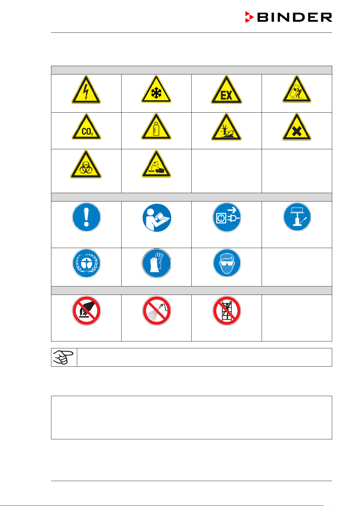
Warning signs
Electrical hazard
Explosive atmosphere
Pollution Hazard
Harmful substances
or chemical burns
Mandatory action signs
plug
Environment protection
Wear protective gloves
Prohibition signs
water
1.2.3 Pictograms
CO
suffocation hazard
2
Biohazard
Mandatory regulation
Very cold surface
Gas cylinders
Risk of corrosion and /
Read operating
instructions
Disconnect the power
Stability hazard
Lift with mechanical
assistance
Wear safety goggles
Do NOT touch
Do NOT spray with
Do NOT climb
Information to be observed in order to ensure optimum function of the product.
1.2.4 Word message panel structure
Type / cause of hazard.
Possible consequences.
∅ Instruction on how to avoid the hazard: prohibition
Instruction on how to avoid the hazard: mandatory action
Observe all other notes and information not nec essarily emphasized in the same way, in order to avoid
disruptions that could result in direct or indirect injury or property damage.
UF V (E3) 09/2018 Page 8/116
Page 9
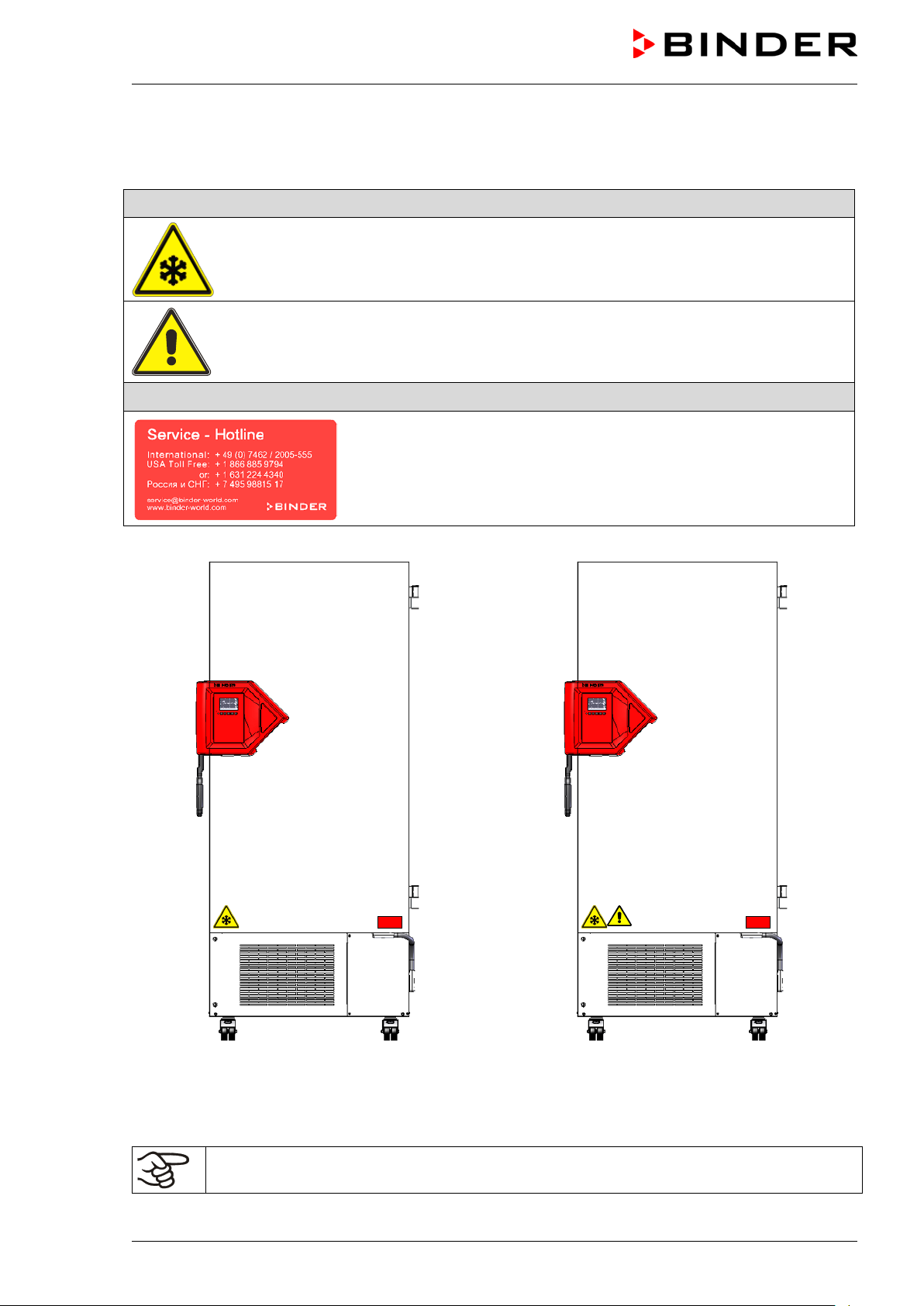
1.3 Localization / position of safety labels at the chamber
The following labels are located on the chamber:
Pictograms (Warning signs)
Very cold surface: Risk of freezing
Risk of injury.
Observe the safety instructions in the operating manual.
Service label
(only UF V - UL and UF V with optional CO
emergency cooling)
2
UF V regular chamber UF V-UL and UF V with optional
emergency cooling
CO
2
Figure 1: Position of labels on the ultra-low temperature freezer UF V
Keep safety labels complete and legible.
Replace safety labels that are no longer legible. Contact BINDER Service for these replacements.
UF V (E3) 09/2018 Page 9/116
Page 10
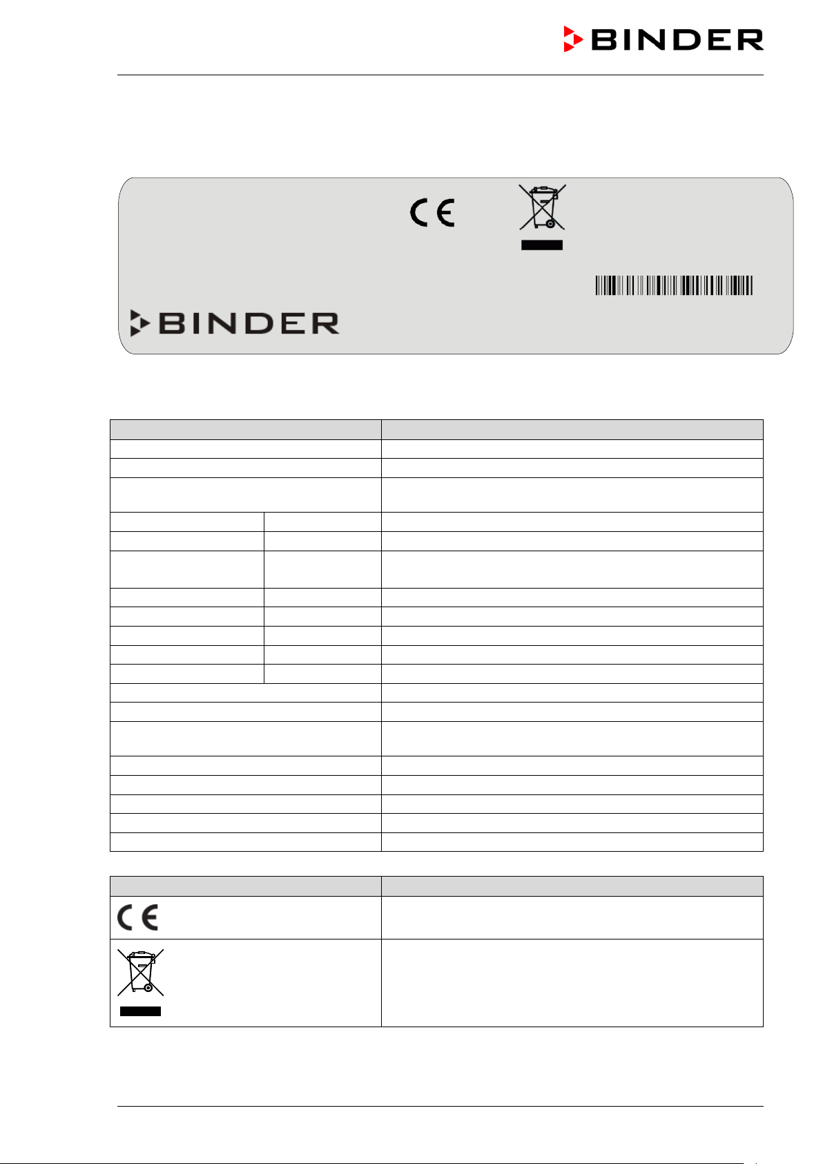
Indications of the type plate (example)
Information
BINDER
Manufacturer: BINDER GmbH
UF V 500
Model designation
freezer
Serial No.
000000000000
Serial no. of the chamber
Built
2017
Year of construction
Nominal temperature
-86 °C
-123 °F
IP protection
20
IP type of protection acc. to standard EN 60529
Temp. safety device
DIN 12880
Temperature safety device acc. to standard DIN 12880
Class
---
Class of temperature safety device
Art. No.
9020-0347
Art. no. of the chamber
Project No.
---
Optional: Special application acc. to project no.
1,60 kW
Nominal power
9,0 A
Nominal current
Nominal voltage +/- 10%
at the indicated power frequency
1 N ~
Current type
Max. operating pressure 28 bar
Max operating pressure in the refrigerating system
Stage 1: R290 – 0,15 kg
Cooling 1st stage: Refrigerant type, filling weight
Stage 2: R170 – 0,15 kg
Cooling 2nd stage: Refrigerant type, filling weight
Contains hydrocarbon gases
Contains hydrocarbon gases
Symbol on the type plate
Information
Nominal temp.
-86 °C
1,60 kW / 9, 0 A
Max. operating pressure 28 bar
-123 °F
230 V / 50 Hz
Stage 1: R290– 0,15 kg
IP protection
20 Stage 2: R170 – 0,15 kg
Safety device
DIN 12880
1 N ~
Class
3.1
Art. No.
9020-0347
Project No.
Built
2017
ULTRA.GUARD ULT Freezer
BINDER GmbH
www.binder-world.com
UF V 500
Serial No. 00000000000000
1.4 Type plate
The type plate sticks to the left side of the chamber, bottom right-hand.
Im Mittleren Ösch 5
78532 Tuttlingen / Germany
E3
Made in Germany
Figure 2: Type plate (example UF V 500 (E3) standard chamber)
ULTRA.GUARD ULT Freezer Device name: “ULTRA.GUARD” ultra-low temperature
Nominal temperature
230 V / 50 Hz
UF V (E3) 09/2018 Page 10/116
CE conformity marking
Electrical and electronic equipment manufactured / placed
on the market in the EU after 13 August 2005 and to be
disposed of in a separate collection according to directive
2012/19/EU on waste electrical and electronic equipment
(WEEE).
Page 11

1.5 General safety instructions on installing and operating the chamber
With regard to operating the chamber and to the installation location, please observe the DGUV guidelines
213-850 on safe working in laboratories ( f or merly BGI/GUV-I 850-0, BGR/GUV-R 120 or ZH 1/119, issued
by the employers’ liability insurance association) (for Germany).
BINDER GmbH is only responsible for the safety features of the chamber provided skilled electricians or
qualified personnel authorized by BINDER perform all maintenance and repair, and if com ponents relating
to chamber safety are replaced in the event of failure with original spare parts.
To operate the cham ber, use only original BINDER accessories or accessories fr om third-party suppliers
authorized by BINDER. The user is responsible for any risk caused by using unauthorized accessories.
CAUTION
Danger of overheating.
Damage to the chamber.
∅ Do NOT install the chamber in unventilated recesses.
Ensure sufficient ventilation of the installation site for dispersal of the heat.
CAUTION
Leakage of refrige rant in the event of a chamber defect.
Danger to the environment.
Ensure sufficient ventilation of the installation site.
Do not operate the chamber in hazardous locations.
DANGER
Explosion hazard.
Danger of death.
∅ Do NOT operate the chamber in potentially explosive areas.
∅ KEEP explosive dust or air-solvent mixtures AWAY from the chamber.
The chamber does not does not dispose of any measures of explosion protection.
DANGER
Explosion hazard.
Danger of death.
∅ Do NOT introduce any substance into the chamber which is combustible or explosive at
working temperature.
∅ NO explosive dust or air-solvent mixture in the inner chamber.
Any solvent contained in the charging material must not be explosive or inflamm able. I.e., irrespective of
the solvent concentration in the steam room, NO explosive m ixture with air must form. T he temperature
inside the chamber mus t lie below the flash point or below the sublimation point of the charging material.
Familiarize yourself with the physical and chemical properties of the charging material.
Familiarize yourself with any potential health risks caused by the charging material. Take adequate
measures to exclude any risk prior to putting the chamber into operation.
UF V (E3) 09/2018 Page 11/116
Page 12
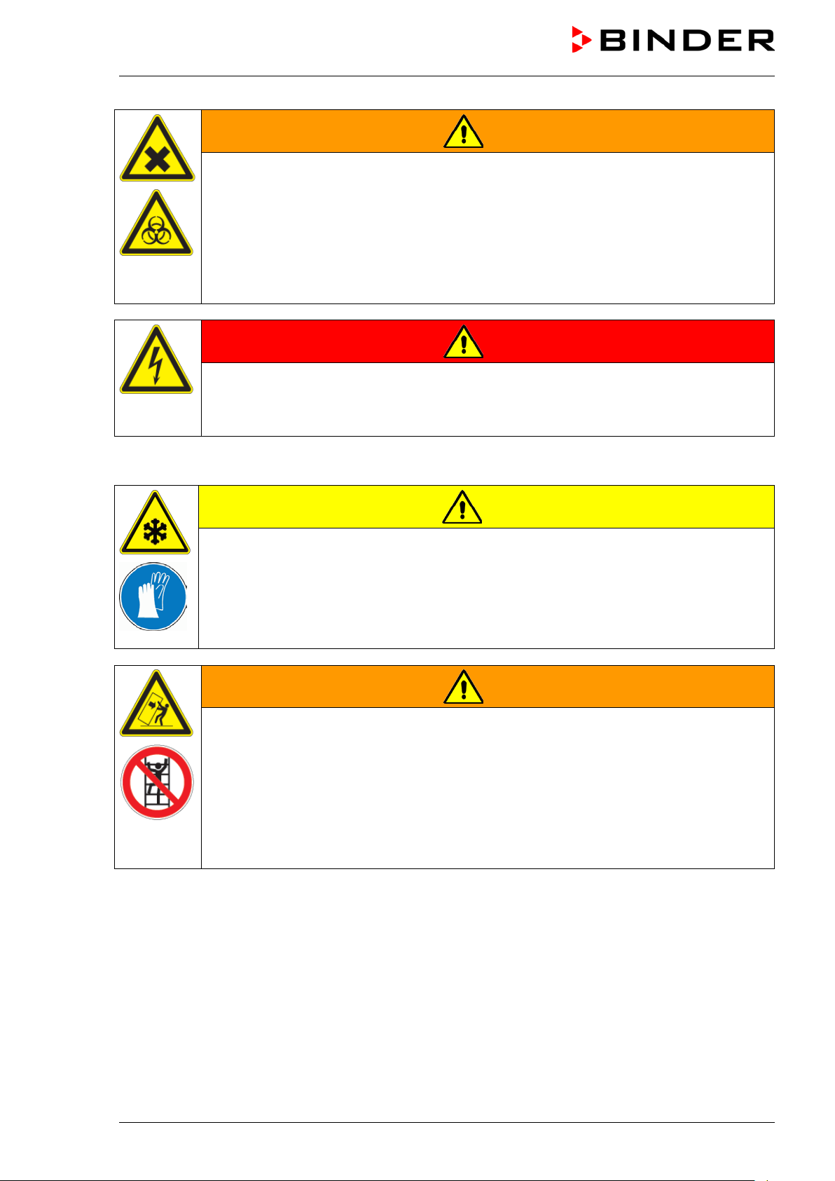
WARNING
Contamination with toxic, infectious or radioactive substances.
Danger of intoxication.
Danger of infection.
Protect the interior of the chamber against contamination by toxic, infectious or radioac-
tive substances.
Take appropriate measures when bringing in or taking out toxic, infectious or radioac-
tive substances.
DANGER
Electrical hazard.
Danger of death.
∅ The chamber must NOT become wet during operation or maintenance.
The chamber s were produced in accordance with VDE regulations and were routinely tested in accordance to VDE 0411-1 (IEC 61010-1).
CAUTION
The inner surfaces become very cold during operation.
Danger of injury by freezing on.
∅ Do NOT directly touch the inner surfaces or the charging material during operation.
∅ AVOID skin contact with the inner surfaces and accessory equipment.
Wear protective gloves when opening the inner doors and during manipulation.
WARNING
Stability hazar d .
Danger of injury.
Damage to the chamber an d th e charging material.
Housing cover breakaway.
∅ Do NOT climb on the lower housing cover.
∅ Do NOT load the lower housing cover with heavy objects while the chamber door is
open.
UF V (E3) 09/2018 Page 12/116
Page 13
1.6 Intended use
ULTRA.Guard™ ultra-low tem perature fr eezers UF V are tec hnical equipm ent and intended solely for use
at work. They are suitable are designed for safe storage of varied materials at temperatures up to –86 °C /
-122,8 °F, especially for long-term storage of biological, m edical, and chemical samples at cons tant low
temperature. T hey are suitable for the dom ains Pharm acy, Medicine, Life Sciences, plastic industr y, electronic components, food etc.
Freezers are designed for storage of harmless m aterials. None of the components of the charging material must be able to form an ex plosive mixture with air. Any component of the c harging material must NOT
be able to release toxic gases.
Following the instructions in this operating manual and conducting regular maintenance work
(chap. 24) are part of the intended use.
Other applications are not approved.
The chambers are not classified as medical devices as defined by the Medical Dev ice Directive
93/42/EEC.
WARNING: If customer should use a chamber running in non-supervised continuous operation, we strongly recommend in case of inclusion of irrecoverable specimen or samples to
split such specimen or samples and store them in at least two chambers, if this is feasible.
The charging material shall not contain any corrosive ingredients that may damage the machine components made of stainless steel. Such ingredients include in particular acids and
halides. Any corrosive damage caused by such ingredients is excluded from liability by
BINDER GmbH.
In case of foreseeable use of the chamber there is no risk for the user through the integration of the
chamber into systems or by special environmental or operating conditions in the sense of EN 610101:2010. For this, the intended use of the chamber and all its connections must be observed.
1.7 Operating instructions
Depending on the application and location of the chamber , the operator of the cham ber mus t provide the
relevant information for safe operation of the chamber in a set of operating instructions.
Keep these operating instructions with the chamber at all times in a place where they are
clearly visible. They must be comprehensible and written in the language of the employees.
UF V (E3) 09/2018 Page 13/116
Page 14

1.8 Measures to prevent accidents
The operator of the chamber must observe the following regulation: Occupational Safety Regulations.
Operation of refr igeration chambers , heat pumps and cooling systems (G UV-R 500 chap. 2.35) (for Germany).
Following measures have been taken by the manufacturer in order to prevent ignition and explosions:
• Indications of the type plate
See operating manual chap. 1.4
• Operating manual
An operating manual is available for each chamber.
• Temperature monitoring
The chamber has a temperature display which can be read from outside.
An additional temperature safety device is built into the device. A visual and an audible signal (buzzer)
show exceeding of the temperature.
• Safety, measurement and control devices
The safety, measuring, and control devices are easily accessible.
• Electrostatic charge
The interior parts are grounded.
• Non-ionizing radiation
Non-ionizing radiation is not intentionally produced, but released only for technical reasons by electrical
equipment (e.g. electric m otors). The machine has str ong permanent magnets. If persons with active
implants (e.g. pacem akers, def ibrillators) keep a safe distance (distance of f ield source to implant) of
30 cm, an influence of these implants can be excluded with high probability.
• Protection against touchable surfaces
Tested according to EN ISO 13732-3:2008.
• Floors
See operating manual chap. 3.4 for installation
• Cleaning
See operating manual chap. 24.3.
UF V (E3) 09/2018 Page 14/116
Page 15

2. Chamber descript ion
The ULTRA.Guard™ ultra-low tem perature f reezers UF V were produc ed with great care using the latest
tools for development and production. T hey were optimized for safe long-term stor age of samples in the
ultra-low temperature range. You can operate the fr eezer in a temperature range from -86 °C / -122.8 °F
up to -40 °C / -40 °F.
The UF V-UL chambers are regularly equipped with the advanced voltage booster AVC (option for UF V).
The freezers are available for several different voltages.
Door access system (option):
The freezers are optionally available with an electrom echanical door lock ing and electronic acces s contr ol
via NumPad, permitting personalized access control.
A pushbutton permits opening the electrom echanical door locking without using your hands. A pull-tight
function automatically closes the outer door when slightly open.
Lockable protective flap for the main power switch (option)
An additional locking system with key for the freezer’s main power switch is optionally available.
Controller
The efficient RD4 chamber controller is equipped with a multitude of operating functions, in addition to
recorder and alarm functions. Set-point entry is easily accomplished directly via the chamber contr oller
and is also possible directly with a computer via Intranet in connection with the comm unication software
APT-COM™ 3 DataControlSystem (option, chap. 22.2).
Temperature setting is ac curate to a tenth of a degree. The controller is mounted at the optimal height for
operation.
The controller offers an error diagnostics system generating audible and visual warning and alarm messages.
Chambers with the option “battery-buffered alarm system”: During power failure, alarm f unction and control remain active during 72h. The controller provides password protection for the setting menus.
The controller monitors ambient temperature and issues an alarm if it exceeds an adjustable value.
Housing
The inner chamber and the ins ide of the ins ulated out er door are made of stainless steel (G er man materi-
al no. 1.4016, U S equivalent AISI 430). The housing including all corners and edges is RAL 7035 varnished. The inner surfaces are sm ooth and ther efore eas y to clean. Easy front access permits f ilter c leaning without tools. Two 28 m m access por t serve to introduce a sensor cable of a meas uring device, the
upper one also to connect the optional CO
The buildup of ice in the door area is minim al due to perfect closing of the inner and outer doors. Pr ecise
spatial distribution of the cold in the interior ensures stor age of all sam ples at an identical storage tem perature. The prevention of thermal br idges protects against defrosting. The com bination of vacuum insulation panels (V technology) and CFC-free polyurethane foaming maximizes the cold storage capacity.
emergency cooling
2
The freezer has two com partment doors. You can insert stainless s teel shelves are m ak e optim um us e of
the interior. You can flexibly arrange the shelves to use the interior in a variable and optimum manner .
Inventory racks (stainless steel storage racks with cryo boxes, chap. 23) are optionally available.
Castors with locks serve to move the freezer.
UF V (E3) 09/2018 Page 15/116
Page 16

Cooling system
The powerful, energy-efficient and low-noise refrigerating machine uses the environmentally friendly
“green” refrigerants R 290 (pr opane) und R170 (ethane). They are completely free of HCFCs (hydrochlorofluorocarbons) and CFCs (chlorofluorocarbon).
st
Control of the two-stage refrigerating m achine: T he 1
nd
stage cooling turns on depending on the temperature.
2
stage cooling immediately turns on. In addition, the
Safety
Thanks to the standard overtemperature safety device, the set temperature is maintained also in case of a
controller failure.
In case of power failure at -80 °C / -112 °F, a tem perature of -60 °C / -76 °F will not be exceeded in an
empty freezer for at least 2.5 hours, in a loaded freezer (measured with a 30 kg / 66 lb water load) for
approx. 7 hours.
Battery-buffered alarm system (option): The f reezer is optionally equipped with a rechargeable battery
(12 V, 7.2 Ah). Battery voltage is regularly monitored. An alarm indicates too low battery voltage. You can
check battery voltage in the “USER” menu.
The advanced voltage booster optionally available provides automatic voltage compensation through a
buck/boost converter (chap. 4.6).
An error diagnostics system m onitors the chamber functions and generates audible and visual warning
and alarm messages. The door is monitored for being closed.
The CO
em ergency cooling (option, chap. 21) off ers additional r efrigeration, i.e., f ollowing introduction of
2
a heat load, in case of a power failure or failure of the cooling system.
Data monitoring and rec o rding
The chamber is regularly equipped with a zero-voltage relay alarm output (chap. 14.4.7) and optionally
with an analog output (chap. 22.3) for integration into customer systems.
The freezer is regularly equipped with an Ethernet interface (chap. 22.1) for computer communication,
enabling monitoring via a network. The BINDER com munication sof tware APT-COM™ 3 / 4 DataContr olSystem (option, chap. 22.2) permits network ing of up to 40 chambers and connection to a computer, as
well as recording and representing temperature data.
A data logger independent from the chamber controller (option, chap. 22.4) serves to independently record the temperature values, data given out in compliance with FDA guideline 21 CFR part 11.
UF V (E3) 09/2018 Page 16/116
Page 17
Optional equipment:
“Door access system”
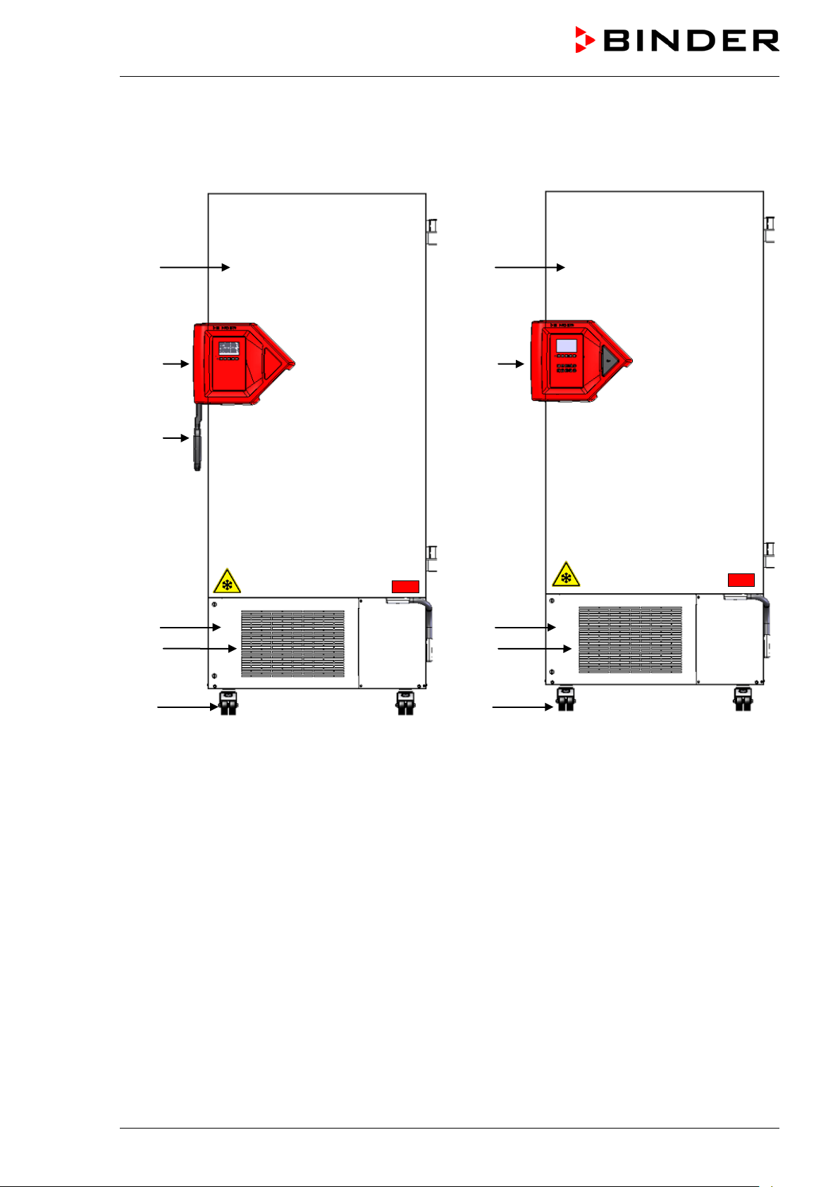
2.1 Chamber overview
(A)
(B)
(C)
(A)
(B)
(D)
(E)
(F)
Standard equipment
Figure 3: Ultra-low temperature freezer UF V (example UF V 700), front view
(A) Outer door
(B) Door lock and controller housing (description chap. 2.2)
(C) Door handle
(D) Compressor housing
(E) Air filter flap (checking and cleaning / replacing the filter chap. 24.4.1)
(F) Castors (front castors lockable by breaks)
(D)
(E)
(F)
UF V (E3) 09/2018 Page 17/116
Page 18
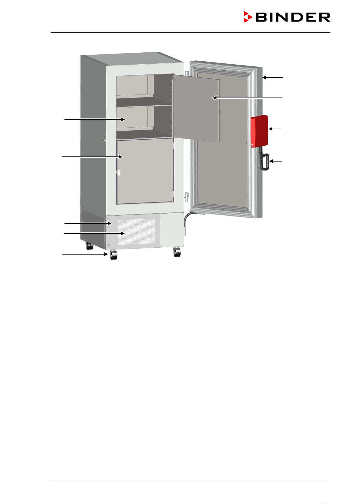
(G)
(
(D)
(E)
(F)
(A)
(H)
(B)
(C)
H)
Figure 4: Ultra-low temperature freezer UF V 700, open
(A) Outer door
(B) Door lock and controller housing (description chap. 2.2)
(C) Door handle
(D) Compressor housing
(E) Air filter flap (checking and cleaning / replacing the filter chap. 24.4.1)
(F) Castors (front castors lockable by breaks)
(G) Compartment with variable shelf
(H) Compartment door
UF V (E3) 09/2018 Page 18/116
Page 19
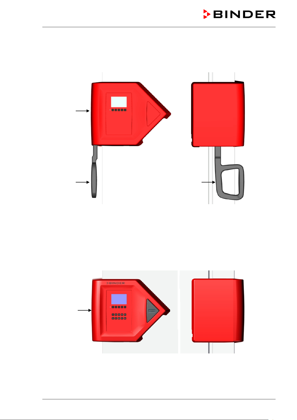
2.2 Door lock and controller housing
The controller operator panel is integrated in the freezer‘s door lock and controller housing (B).
With the standard chamber a door handle (C) serves to open and close the chamber door.
(B)
(C) (C)
Front view Left chamber side
Figure 5: Standard chamber: Door lock and controller housing with controller operator panel and door
handle
Chambers with the “Door access system “option are equipped with an electromechanical door lock ing and
electronic access control via NumPad.
(B)
Front view Left chamber side
Figure 6: Chamber with “Door access system” option: Door lock and controller housing with Numpad,
controller operator panel and pushbutton “OPEN” to open the door
UF V (E3) 09/2018 Page 19/116
Page 20
A pushbutton permits opening the electrom echanical door locking with-
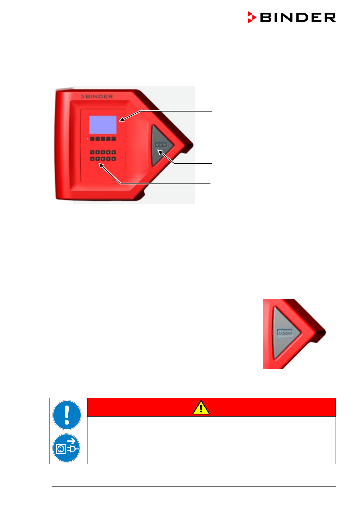
2.2.1 Operating the NumPad (option “Door access system”)
Combined with the electromechanical door loc king the NumPad permits personalized access control to
the freezer.
(1)
(2)
(3)
Figure 7: Door lock and controller housing with “Door access system” option:
Numpad, controller operating panel and pushbutton “OPEN” to open the chamber door
(1) Controller RD4 operating panel
(2) Pushbutton “OPEN” to open the chamber door
(3) NumPad to control the electromechanical door locking
2.2.2 Operating the electromechanical door locking (option “Door access system”)
out using your hands. A pull-tight function automatically closes the outer
door when slightly open.
Opening the door:
Firmly press the one-touch pushbutton “OPEN”. You can now open the
door.
Closing the door:
Firmly press on the door f or at least 2 seconds until the automatic door
mechanism is activated and closes the door tightly.
Figure 8: Pushbutton “OPEN”
to open the door
UF V (E3) 09/2018 Page 20/116
Risk of locking in a person.
Danger of death.
Before closing doors, make sure that nobody is inside.
Pull the power plug before entering the interior (e.g. for cleaning purposes).
DANGER
Page 21
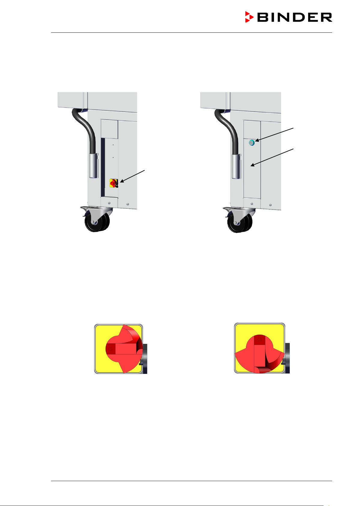
2.3 Main power switch
The main power switch is located on the bottom right side of the chamber.
In addition, a lock able protective flap covering the main power switch is optionally available. It can be un-
locked with a key and then removed.
(4)
Standard chamber Chamber with optional lockable protective flap
Figure 9: Position of the main power switch and the lockable protective flap (option) on the right side of the
chamber
(5a)
(5)
(4) Main power switch
(5) Lockable protective flap (option)
(5a) Key lock of the optional lockable protective flap
Off Onn
Figure 10: Main power switch (4) on the right side of the chamber
UF V (E3) 09/2018 Page 21/116
Page 22
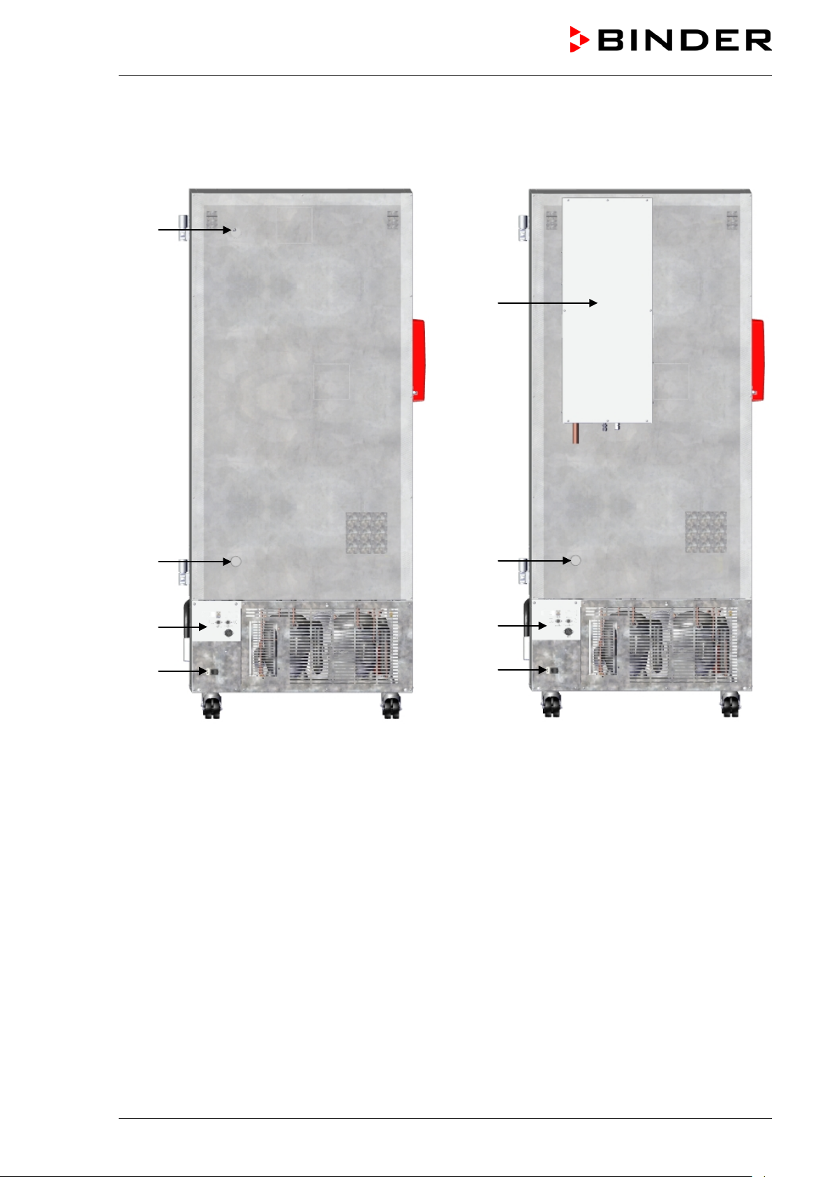
2.4 Chamber rear
(6a)
(6b)
(J)
(6b)
(I)
(7)
Chamber without CO
emergency cooling Chamber with CO2 emergency cooling
2
(I)
(7)
Figure 11: Chamber rear
(6a) 28 mm acces s port to connect the der CO
emergency cooling (option) or for cable of a supplemen-
2
tary measuring device
(6b) 28 mm access port, e.g., for cable of a supplementary measuring device
(7) Connecting socket for IEC connector plug with strain relief
(I) Connection panel
(J) CO
emergency cooling (option, chap. 21)
2
(option)
UF V (E3) 09/2018 Page 22/116
Page 23
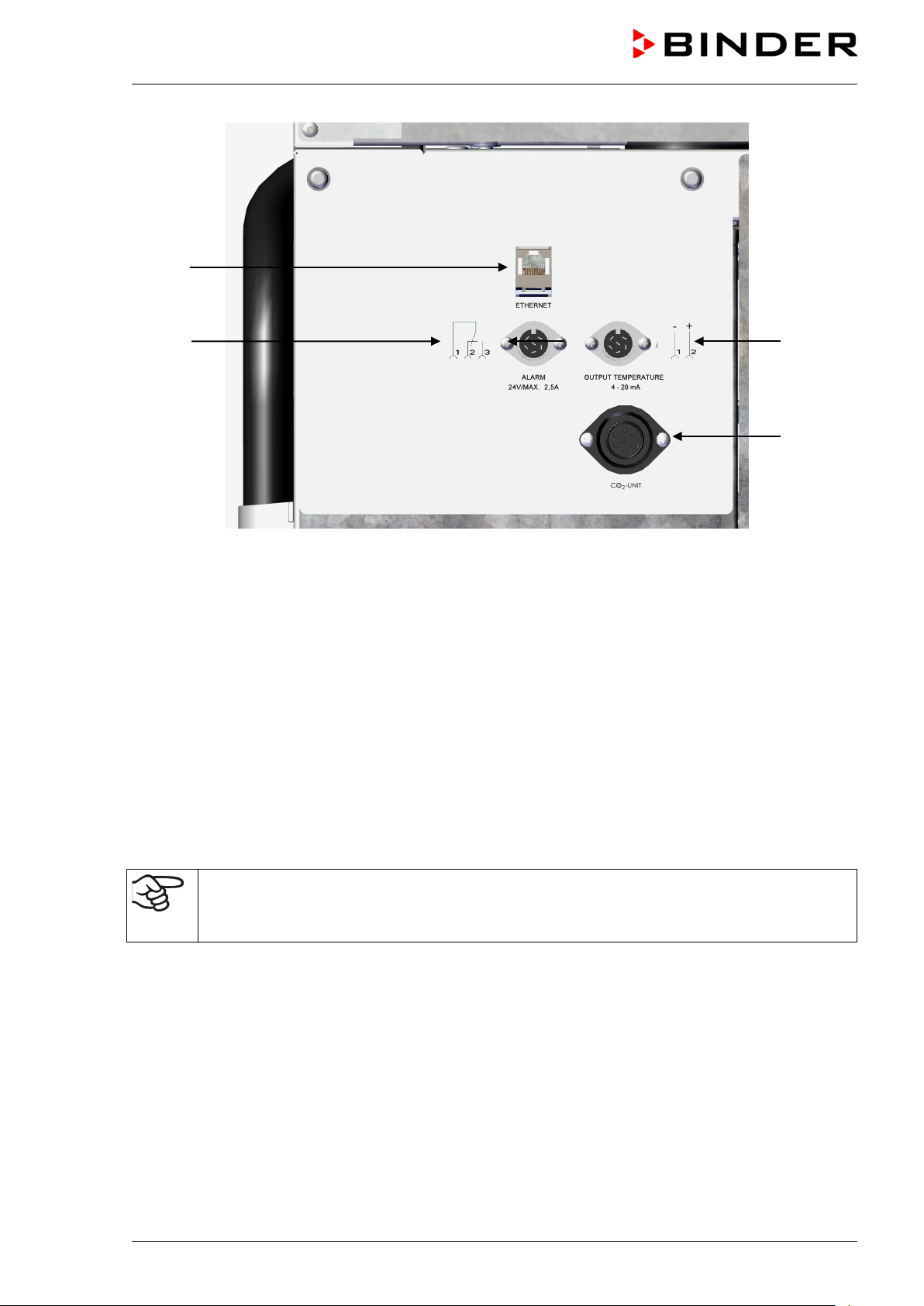
(8)
(9)
Figure 12: Connection panel (I) on the chamber rear
(10)
(11)
(8) Ethernet interface (Chap. 22.1)
(9) Connection socket for zero-voltage relay alarm contact (chap. 14.4.7)
(10) Connection socket for analog output 4-20 mA (option, chap. 22.3)
(11) Connection socket for the electrical connection of the CO
emergency cooling (option, chap. 21)
2
2.5 Doors
2.5.1 Outer door
The outer door m ust be closed while the chamber is operating norm ally in order to ensure stable conditions in the inner chamber.
2.5.2 Compart m ent door s
The freezer interior is divided into in 4 compartm ents, which are is olated against the surrounding with two
doors. This permits bringing in or removing the samples of an individual compartm ent without remar kably
affect temperature in the other compartments.
Delay time for the door open alarm :
After closing the outer door, the door open alarm is switched off for a programmable delay time
(factory setting: 1 minute).
The compartm ent doors rem ain closed by magnetis m when opening the outer door without need for closing them mechanically.
Open the inner doors as shortly as possible to avoid a temper ature rise inside the f reezer. The m aximum
angle of aperture is 100°.
UF V (E3) 09/2018 Page 23/116
Page 24

2.6 Drain well for condensate during defrosti ng (option)
The drain well collects the dripping water when defrosting.
Strong magnets on the drain well sides fix it on the chamber.
Attach the drain well to the freezer. Its first level rests on the lower housing panel. T he gas ket is aligned to
the bottom edge of the freezer interior.
Figure 13: Freezer with drain well (option)
While defr osting use adhesive tape to keep the door above the drain well (drain off position). Now the
melted condensate flows into the drain well.
Place a reservoir below the hole at the front left corner of the drain well, so that the water can drain off.
UF V (E3) 09/2018 Page 24/116
Page 25
3. Completeness of delivery, transportation, stora ge , and installat ion
3.1 Unpacking, and checking equipment and completeness of delivery
After unpacking, please check the chamber and its optional accessories, if any, based on the delivery
receipt for completenes s and for transportation damage. Inform the c arrier immediately if transportation
damage has occurred.
Caution: The drain well is placed under the chamber between the castors. Please rem ove it before unpacking the freezer!
CAUTION
Sliding or tilting of the chamber.
Damage to the chamber.
∅ Do NOT lift the chamber using the door, the door lock and controller housing or the
lower housing.
∅ Do NOT lift the chamber by hand.
∅ Do NOT transport the chamber horizontally.
Keep the chamber in upright position. Max. angle of inclination during transport: 10°.
Lift the chamber using technical devices (fork lifter) from the pallet. Set the fork lifter
laterally or from the rear in the middle of the chamber. Make sure to place all the lateral
supports of the chamber on the forks (check: the fork protrudes at the opposite chamber side).
Wear suitable shoes (safety shoes).
The final tests of the manufactur er may cause traces of the shelves on the inner surf aces. This has no
impact on the function and performance of the chamber.
Please remove any transportation protection devices and adhesives in/on the chamber and on the doors
and remove the operating manuals and accessory equipment.
Remove any protective lamination sheet on the inner metal surfaces prior to commissioning.
Wait at least 8 hours following transport with technical devices (chap. 3.2.2) before start-up.
If you need to return the cham ber, please use the original packing and observe the guidelines for safe
lifting and transportation (chap. 3.2).
For disposal of the transport packing, see chap. 25.1.
Scope of delivery
• Ultra-low temperature freezer UF V
• 3 shelves and 12 shelf holders with screws
• DIN plug for the zero-voltage relay alarm output
• 2 spacers for rear wall distance.
• Operating manual
UF V (E3) 09/2018 Page 25/116
Page 26
CAUTION
Note on second-hand chambers (Ex-Demo-Units)
Second-hand chambers are cham bers that have been used for a short time for test s or exhibitions. They
are thoroughly tested before resale. BINDER ensures that the cham ber is technically sound and will work
flawlessly.
Second-hand chambers are marked with a stick er on the c hamber door. Please remove the s ticker before
commissioning the chamber.
3.2 Guidelines for safe lifting and transportation
3.2.1 Moving t he f r eezer i nside a building
Before moving the freezer unlock the front castors. T he castors ar e designed only for moving the freezer
inside a building. This is possible only on a floor without joints (e.g. no tiles) and when avoiding shocks. In
this case, the freezer must not be empty (max. load see technical data, chap. 27.4).
If you want to move the chamber across a large door threshold or into an elevator to change the floor,
empty the freezer and put all shelves on the bottom of the interior.
If you incline the chamber by less than 5°, you can directly turn it on after moving (at least 10 minutes after
turning off). Otherwise, wait at least 8 hours until putting it into operation again.
As soon as the chamber has reached its destination, lock the front castors.
Wear suitable shoes (safety shoes) when moving the freezer.
Over very short distances (within reach of the power cable), you can move the freezer while operating.
If you turned off the chamber (turning off at the main power switch, pulling the power plug), wait at least 10
minutes after moving until you turn on again the chamber in order to protect the refrigeration machine
against damage.
Too quick restart of the refrigeration machine.
Damage to the chamber.
After turning off wait 10 minutes before turning on the freezer again.
UF V (E3) 09/2018 Page 26/116
Page 27
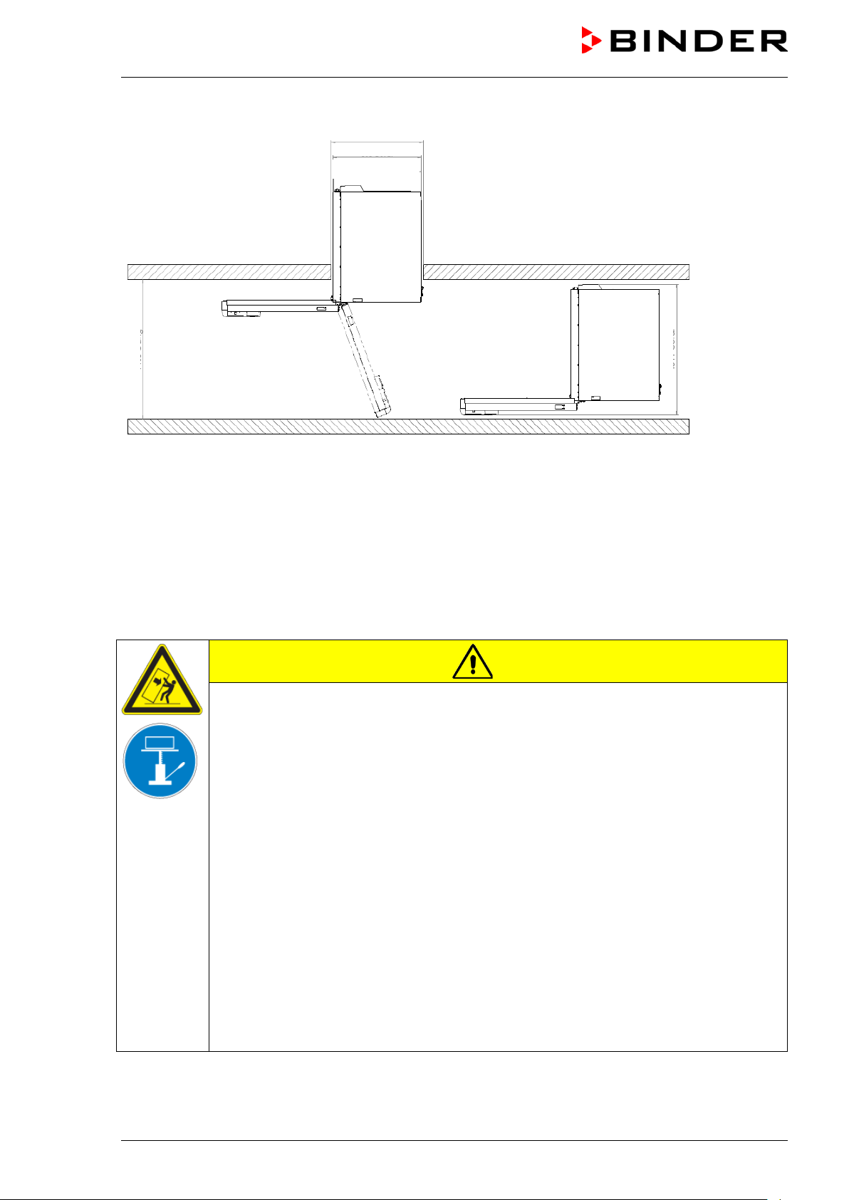
830 mm
900 mm
1400 mm
1000 mm (UF V 500)
To move the freezer through narrow passages (doors, narrow corridors), open the chamber door:
1280 mm (UF V 700)
Figure 14: UF V with open chamber door
For transport outside a building use technical equipment (chap. 3.2.2).
3.2.2 Transport out si de a building
Before moving the cham ber unlock the fr ont cast ors. T he cas tors ar e designed only for moving the chamber inside a building (respect the information given in chap. 3.2.1).
After operation, please observe the guidelines for temporarily decommissioning the chamber (chap. 25.2).
CAUTION
Sliding or tilting the chamber.
Damage to the chamber.
∅ Do NOT lift or transport the chamber using the door, the door lock and controller hous-
ing or the lower housing.
∅ Do NOT lift the chamber by hand
∅ Do NOT transport the chamber horizontally.
Transport the chamber only in its original packaging.
Secure the chamber with transport straps for transport.
Keep the chamber in upright position. Max. angle of inclination during transport: 10°.
Place the shelves on top of each other on the bottom of the interior.
Lift the chamber using technical devices (fork lifter) and place it on the transport pallet.
Set the fork lifter laterally or from the rear in the middle of the chamber. Make sure to
place all the lateral supports of the chamber on the forks (check: the fork protrudes at
the opposite chamber side).
Transport chambers ONLY with the original transport pallet. Set the fork lifter only to
the pallet. Without the pallet the chamber is in imminent danger of overturning
Wear suitable shoes (safety shoes).
UF V (E3) 09/2018 Page 27/116
Page 28
• Permissible ambient temperature range for transport: -10 °C / 14°F to +60 °C / 140°F.
You can order transport packing and rolling pallets for transportation purposes from BINDER Service.
Freezer transport in upright position is mandatory in order to avoid oil running out of the engine casing and
resulting damages to the cooling system. Max. angle of inclination during transport: 10°.
Wear suitable shoes (safety shoes) during transport.
Following transport, wait at least 8 hours until start-up.
3.3 Storage
Intermediate storage of the chamber is possible in a closed and dry room. Observe the guidelines for
temporary decommissioning (chap. 25.2).
• Permissible ambient temperature range for storage: -10 °C / 14°F to +60 °C / 140°F.
• Permissible ambient humidity: max. 70% r.h., non-condensing
Secure the chamber against unintentional rolling by locking the front castors.
When after storage in a cold location you transfer the cham ber to its warmer installation site, condens a-
tion may form in the inner c hamber or on the housing. Before start-up, wait at least one hour until the
freezer has attained ambient temper ature and is completely dry. According to the type of transport that
has taken place (chap. 3.2) you may have to wait at least 8 hours until start up.
3.4 Location of installation and ambient conditions
The freezer is designed for setting up inside a building (indoor use) . Set up the chamber on a flat, even
surface, free from vibration and in a well-ventilated, dry location. Lock the front castors and align the
chamber using a spirit level. The site of installation must be capable of supporting the cham ber’s weight
(see technical data, chap. 27.4).
CAUTION
Danger of overheating.
Damage to the chamber.
∅ Do NOT set up chambers in non-ventilated recesses.
Ensure sufficient ventilation for dispersal of the heat.
CAUTION
Leakage of refrige rant in the event of a chamber defect.
Danger to the environment.
Ensure sufficient ventilation of the installation site.
• Permiss ible ambient tem per ature range f or operation: +18 °C / 64.4 °F to +32 °C / 89.6 °F. At elevated
ambient temperature values, fluctuations in temperature can occur.
The ambient temperature should not be substantially higher than the indicated ambient temperature of +25 °C / 77 °F to which the specified technical data relate. For other ambient conditions, deviations from the indicated data are possible.
Prevent the freezer from sucking warm air from other devices.
UF V (E3) 09/2018 Page 28/116
Page 29
Avoid direct solar radiation on the chamber. Do not place the freezer in direct vicinity of chambers with a high heat emission.
• Permissible ambient humidity: 70% r.h. max., non-condensing.
• Installation height: max. 2000 m / 6561.7 ft above sea level.
Minimum distances:
• between several chambers: 250 mm / 9.84 in
• Wall distance, rear: 100 mm / 3.94 in (spacer is supplied, see chap. 4.2)
• Wall distance, laterally, on the side without door hinge: 100 mm / 3.94 in
• Wall distance, laterally, on the side with door hinge: 240 mm / 9.45 in.
• Spacing above the chamber: 100 mm / 3.94 in
Ventilation openings must not be blocked. Ens ure a dis tance of at least 100 mm / 3.94 in to the ventilation
openings on the freezer’s front and rear.
To completely separate the chamber from the power supply, you must disconnect the power
plug. Install the chamber in a way that the power plug is easily accessible and can be easily
pulled in case of danger.
With an incr eased am ount of dust in the am bient air, clean the c ondenser f an (by suction or blowing) several times a year. Check the condenser air filter frequently and clean it if necessary (chap. 24.4.1).
Avoid any conductive dust in the ambiance according to the chamber layout complying with pollution degree 2 (IEC 61010-1).
For the user there is no risk of temporary overvoltages in the sense of EN 61010-1:2010.
Do not install or operate the freezer in potentially explosive areas.
DANGER
Explosion hazard.
Danger of death.
∅ Do NOT operate the chamber in potentially explosive areas.
∅ KEEP explosive dust or air-solvent mixtures AWAY from the vicinity of the chamber.
For freezers with water cooling:
To avoid any possible water damage, provide a floor drain at the location of the device. Select
a suitable installation site to avoid any consequential damage by splashing water.
UF V (E3) 09/2018 Page 29/116
Page 30
4. Installation and c onne c t ions
4.1 Operating instructions
Depending on the application and location of the chamber, the operator of the freezer must provide the
relevant information for safe operation of the chamber in a set of operating instructions.
Keep these operating instructions with the chamber at all times in a place where they are
clearly visible. They must be comprehensible and written in the language of the employees.
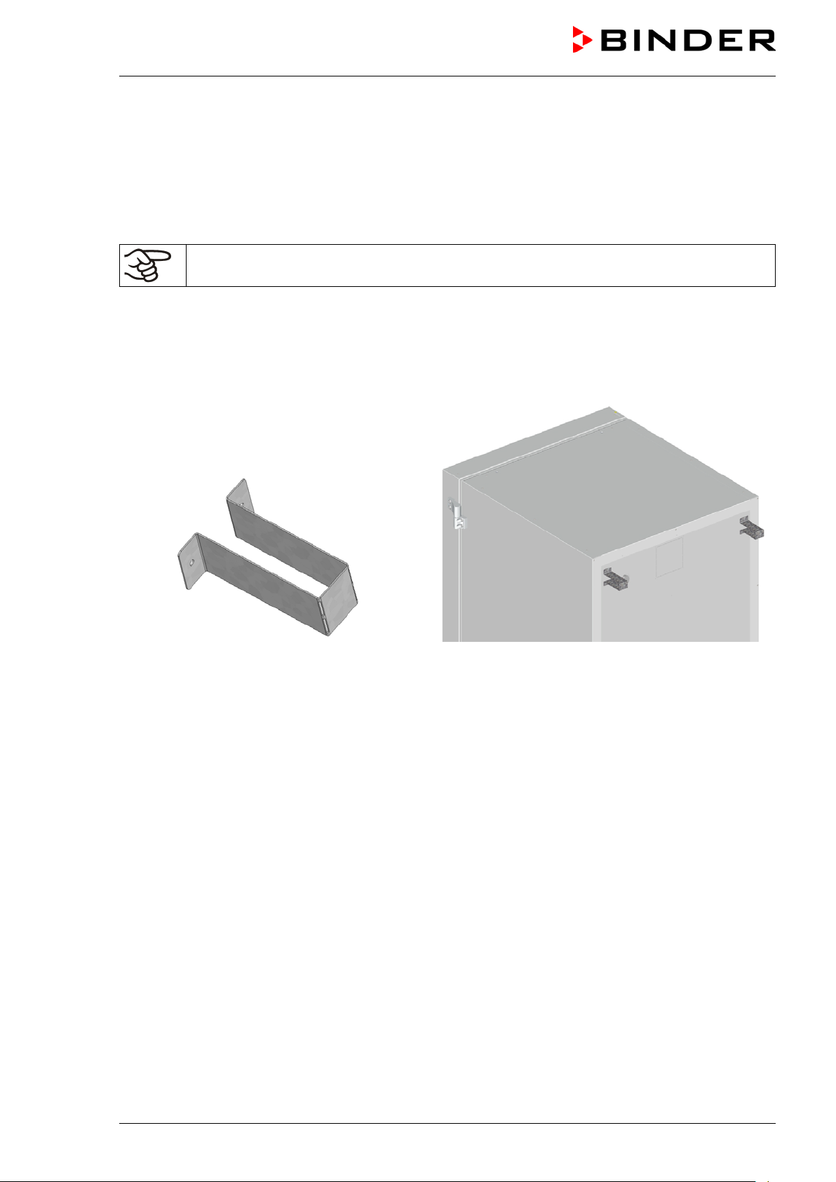
4.2 Spacers for rear wall distance
Please fix both spacers with the supplied screws at the chamber rear. This serves to ensure the prescribed minimum distance to the rear wall of 100 mm / 3.94 in.
Figure 15: Spacer for rear wall distance Figure 16: Rear UF V 700 with mounted spacers
UF V (E3) 09/2018 Page 30/116
Page 31

4.3 Adjustable shelves
The scope of delivery comprises three adjustable shelves. You can mount them and further optional
shelves in different positions of the lateral walls in 24 mm / 1 inch steps. In standard pos ition, the shelves
are placed with a distance of 310m m / 12.2 in, forming the bottom of the com partments, thus making
available the maximum space for optional inventory systems.
It is required to fix the adjustable shelves in or der to avoid that a pers on c ould be locked in the freezer. To
remove a shelf, remove the screws, lift and incline the shelf and then pull it forward
Mounting the adjustable shelves:
• Insert the shelf holders at the desired height into shelf holder bars.
• Insert the shelves and screw them with a Phillips screwdriver to the shelf holders
Figure 17: Inserting the shelf holders Figure 18: Screwing the shelves to the shelf holders
UF V (E3) 09/2018 Page 31/116
Page 32

Chamber size
500
700
Permitted load of individual shelf (regular)
kg / lbs
50 / 110
50 / 110
Permitted total load of all shelves (regular)
kg / lbs
200 / 441
200 / 441
For optimal use of space, we recommend the following shelf positions:
Position of 3 shelves to obtain 4
compartments with equal ceiling
height
Position of 4 shelves (1 x optional)
to obtain 5 compartments with
equal ceiling height
Position of 3 shelves to obtain the
maximum sample storage space: 2
compartments with a ceiling height
of 334 mm / 13.15 in (for racks
4x6) and 2 compartments with a
ceiling height of 279 mm / 11 in (for
racks 4x4)
Insert the shelf holders into the
following positions of the shelf
holder bar (starting from the bottom):
18, 35, 53
Permitted shelf loads:
Insert the shelf holders into the
following positions of the shelf
holder bar (starting from the bottom):
13, 29, 42, 58
Insert the shelf holders into the
following positions of the shelf
holder bar (starting from the bottom):
21, 36, 53
UF V (E3) 09/2018 Page 32/116
Page 33

4.4 Connections of cooling water for chambers with wate r cooling (option)
The water cooling reduces the heat, which is emitted during cooling operation to the ambient air.
An enclosure inside the chamber contains the connection kit for the cooling water inlet and outlet.
„OUT“ „IN“
Figure 19: Connec tions of cooling water on the cham ber rear (cham bers with water cooling), exam ple UF
V 700
“IN” connection for cooling water inlet with external thread 3/4‘‘ and internal thread 3/8‘‘
“OUT” connection for cooling water outlet with external thread 3/4‘‘ and internal thread 3/8‘‘
4.4.1 Connection of cooling wat er out let for water cooling
Fasten the 1/2‘‘ cooling hose to the connection of cooling water outlet “OUT ” on the chamber rear. Observe the following points:
• You can use a part of the supplied water hose for the cooling water outlet. In case another hose is
used, it must be permanently resistant against max. 50 °C / 122 °F and pressure-resistant up to 10 bar.
• Put the hose on the hose nozzle with screwing and secure it with one of the four supplied hose clamps.
Connect the hose nozzle to the connection “OUT” and screw on the union nut.
• For the hose connect ion to the domestic water connection, we recommend to also use the supplied
hose nozzle with screwing and secure it with one of the four supplied hose clamps.
• Before turning on the chamber, check the connection for leaks.
The temperatur e of the ef fluent cooling water is 27 °C up to 29 °C on ac count of the cham ber’s c onstruction.
UF V (E3) 09/2018 Page 33/116
Page 34

4.4.2 Connection of cooling wat er i nlet for water cool i ng
Connect the cooling water outlet before connecting the cooling water inlet.
Requirements for the cooling water:
• Water type: cooling water, air conditioning water, tap water
• Water intake temperature: 8 °C / 46.4 °F up to 23 °C / 73.4 °F
• pH value 4 up to 8
• Water hardnes s of max . 142.8 m g/l (ppm ) = 10 English (Clark ) degrees = 8.32° grains per U.S. gallon
= 1.4285 mmol/l.
• Particle size < 100 µm
• Connection pressure 1 bar up to 10 bar overpressure
• Pressure diff erenc e between inlet and outlet: at least 0, 2 bar; 0,5 bar rec ommended. A higher pressure
difference can result in flow noise.
• The water inlet and outlet should be provided with a shut-off slide or water-tap.
Water demand:
• Average 10-50 l/h, depending on the intake temperature
• Short-term (duration up to 2 minutes) up to 400 l/h
BINDER GmbH is NOT responsible for the water quality at the user’s site.
Any problems and malfunctions that might arise following use of water of deviating quality is
excluded from liability by BINDER GmbH. This includes in particular a high particle content,
which may result in blockage of the water flow control valve.
The warranty becomes void in the event of use of water of deviating quality.
Fasten the 1/2‘‘cooling hose to the connection of cooling water outlet “IN” on the chamber rear. Observe
the following points:
• You can use a part of the supplied water hose for the cooling water inlet. In case another hose is used,
it must be pressure-resistant up to 10 bar.
• Put the hose on the hose nozzle with screwing and secure it with one of the four supplied hose clamps.
Connect the hose nozzle to the connection “IN” and screw on the union nut.
• For the hose connection to the dom estic water connection, we recommend to also use the supplied
hose nozzle with screwing and secure it with one of the four supplied hose clamps.
• Before turning on the chamber, check the connection for leaks.
Water supply is automatically effected via the water connection “IN”.
4.4.3 Connection kit for cooling water
The ultra-low temperature f reezer with water c ooling com es with a connection k it. It consis ts of the following:
• Hose burst protection device
• 4 Hose nozzle with screwing (union nut)
• 4 hose clamps
• 6m water hose 1/2'‘,divisible for inlet and outlet, approved for max. 15 bar, max. 95 °C
UF V (E3) 09/2018 Page 34/116
Page 35

Protection principl e of the hose burst protectio n
The hose burst protection device serves to protect the environment against flooding caused by burst water
hoses. It is intended for the operation of the device at a tap water line. If the freezer is operated in a cycle
of cooling water or air conditioning water, the user should check whether the hose burst pr otection device
provides sufficient protection. This depends mainly on a sufficient medium pressure in the system.
Whenever a st rong water flow of approx. 18 l / min. occurs, e.g. caused by a burst water hose, a valve
automatically cuts off the water supply, which can be heard as a clicking noise. The water supply now
remains shut until it is manually released.
Assembly:
Screw the hose burst protection device onto a water tap with a G¾ inch right turning thread connection.
The connection is self-sealing. Establish the c onnection between the safety kit and the chamber with a
part of the supplied hose. Protect both ends of the hose by the supplied hose clamps.
We rec om m end connec ting the hose as the last s tep in order to avoid twisting the hose while screwing on
the safety kit.
Open the water tap slowly in order to avoid actuating the hose burst protection device.
Figure 20: Assembly of the connection kit
Release of the reflux protection device:
In case the burst protection device has interrupted t he water supply, first f ind the reason and rem ove it as
necessary. Close the water tap. Release the valve by a half left-turn of the upper knurled part. You can
hear the release of the valve as a clicking noise. T ighten the burst protection device against the water tap
by a right turn. Open the water tap slowly afterwards.
Maintenance of the assembly of the hose burst protec tion device:
Calcification can impair valve function. W e recommend an annual inspection by a skilled plumber. The
plumber should remove the saf ety kit to check the valve by hand for proper function and calcification or
blockage.
CAUTION
Danger of calcification.
Impairment of valve function.
Have a plumber inspect the valve annually.
Remove calcifications by citric acid or acetic acid solutions.
Continue by testing the function and tightness of the mounted unit.
Check: Quick ly open the water tap while there is no chamber c onnected – the valve should cut off the
water flux without any delay.
UF V (E3) 09/2018 Page 35/116
Page 36

10% at the
4.5 Electrical connection
The ULTRA.Guard™ ultra-low tem perature freezers UF V are supplied ready for connection and come
with an IEC connector plug.
An internal overload release protects the freezer against excess-current.
Model
UF V
UF V UL
(115 V)
UF V UL
(208-240 V)
• The domestic socket must also pr ovide a protective conductor. Make sure that the connection of the
protective conductor of the domestic installations to the chamber ’s protective conductor m eets the latest technology. The protective conductors of the socket and plug must be compatible!
• Only use original connection cables from BINDER.
• Prior to connection and start-up, c heck the power supply voltage. Compare the values to the specified
data located on the chamber’s type plate (located on the left-hand side of the chamber, bottom righthand, chap. 1.4). We recommend the use of a residual current circuit breaker.
• Observe a sufficient current protection according to the number of freezers that you want to operate.
• W hen c onnecting, please obs erve the regulations spec ified by the local electricity supply company and
as well as the VDE directives (for Germany)
• Pollution degree (acc. to IEC 61010-1): 2
• Over-voltage category (acc. to IEC 61010-1): II
Plug of the power
cable
Grounded plug 230 V at 50 Hz 1N~ 10 A
NEMA 5-20P 115 V at 60 Hz 1N~ 10 A
NEMA 6-20P 208-240 V at 60 Hz 2~ 10 A
Nominal voltage +/-
indicated power frequency
Current
type
Fuse
CAUTION
Danger of incorrect po wer supply voltage.
Damage to the equipment.
Check the power supply voltage before connection and start-up.
Compare the power supply voltage with the data indicated on the type plate.
See also electrical data (chap. 27.4).
To completely separate the chamber from the power supply, you must disconnect the power
plug. Install the chamber in a way that the power plug is easily accessible and can be easily
pulled in case of danger.
• When connecting to power supply pay attention to properly grounding it.
4.6 Advanced voltage booster (option)
With this option, a buck/boost converter automatically compensates for voltage fluctuation.
UF V (E3) 09/2018 Page 36/116
Page 37

Status icons
Temperature
Icon
Signification
Icon
Signification
Icon
Signification
Function
5. Functional overview of the RD4 chambe r controller
The RD4 chamber controller controls the temperature inside the chamber:
You can enter the desired set point value in the “Set points” menu directly at the controller or use the
APT-COM™ 3 DataControlSystem software (option) specially developed by BINDER.
The controller of fers various notifications and alarm m essages with visual and audible indication. All con-
troller setting rem ain valid until the next manual change. They are stored also af ter turning off the chamber.
Temperature value
Text information
Figure 21: Normal display of the RD4 controller (sample values)
Status icons in the controller display
Refrigeration active
Display of activated special controller functions.
1 = CO2 emergency cooling activated
Door open
2 = Emergency cooling test activated
3 = Service setpoint active
Functional controller keys
UF V (E3) 09/2018 Page 37/116
Information
Arrow-up button
Arrow-down button
OK button
Back button
Standby button
Collective alarm
• Navigate between menus, submenus, other functions
• In the setting menu: change setting, decrease value
• Navigate between menus, submenus, other functions
• In the setting menu: change setting, increase value
• Select menu, submenu, function
• In the setting menu: Confirm entry
Back to previous menu level
no function
Page 38

Display of interface configuration (e.g. MAC address, IP
General controller settings (date, time, menu language,
5.1 Menu structure of the controller and access levels
Starting from Normal display, navigate between the menus with the arrow buttons.
With the OK button you enter the setting of further subordinate menu functions.
With the Back button you go back to the previous function and finally back to Normal display.
The available functions depend on the current dependent on the current authorization “User”, “Admin” or
“Service”, for which the entry of a password may be required, depending on the setting.
You can set passwords for different access levels:
• User: The password enables access to the standard operating functions. F actory setting is 00 00 (no
password assigned).
• Admin: The password enables access to advanced contr oller func tions and settings. Factory setting is
00 01.
• Service: The password enables access to all controller functions (for BINDER Service only).
As soon as a password has been assigned, acc ess to the respective functions is block ed and only available after entering the correct password.
Menu Required access level Functions
Setpoints
Chamber info
Settings
“User”
Any user
“Admin”
• Temperature set-point setting
• CO
emergency cooling set-point setting (option
2
• Setting the safety controller
• Activating/deactivating the CO
emergency cooling (op-
2
tion) and the service setpoint, emer gency cooling test (option)
• Configuration display (setup information, controller hardware and software, analog inputs)
• Display of battery condition (“battery-buffered alarm system” option)
•
address)
•
temperature unit, display brightness…)
• Network settings
• Setting the data logger storage interval
• Setting the tolerance ranger limits and delay times for door
open and tolerance range alarm, setting the service setpoint
Service
USB
“Service”
Export: Any user
Import: “Admin”
UF V (E3) 09/2018 Page 38/116
• Access code assignment (“door access system” option)
• Password changing for User and Admin
• Configuration settings (only for BINDER Service)
• Password changing for User and Admin
• Export of configuration, logger, and service data
• Import of configuration data
Page 39

The maxim um permitted deviation from the tem perature set point for tolerance
range alarm
Alarm delay time after opening the door
1 minute
Alarm delay time after leaving the tolerance range
comes valid only after the setpoint has been reached)
Password for „User“ authorization
0 (no locking)
Password for „Admin“ authorization
1
Unless noted otherwise, the figure in this manual s how the func tional range, which is available for the user
with “Admin” authorization level
Note: W hen s pec if ying the path to the respective func tion, the pos s ibly required entry of a password is not
listed.
6. Start up
Following transport, wait at least 8 hours until start-up.
Check that the interior of the freezer is empty. Prior to starting a new freezer or if you do not know what
the freezer was last used for, for hygiene purposes you should clean and disinfect the interior (chap. 24.3).
After connecting the supply lines, turn on the chamber by the main power switch (4) (position 1). The lit
pilot lamp shows the chamber is ready for operation.
The controller shows normal display and controls the temperature to the last entered values.
6.1 Preset factory parameters
The chamber is supplied with the following preset parameters , which can be c hanged in the corresponding menus:
Temperature set point -80 °C / -112 °F
Safety controller
(Following opening the door or chamber startup, the tolerance range alarm be-
Set point type “Limit”
-60 °C / -76 °F
+/- 5 K
60 minutes
6.2 Behavior after turning on the chamber
During the equilibration phase of approx. 8 hours after turning on the chamber, undefined tem perature
conditions occur within the chamber. During this phase, do not place any sample materials in the chamber
CAUTION
Danger of destruction of s amples.
Load the freezer only after equilibration of temperature.
If the function “Language selection at restart” has been activated (chap. 12.5, factory setting ON), the
following settings are checked upon start up:
• Menu language (chap. 12.1):
Use the arrow buttons to select the desired language, confirm with the OK button
UF V (E3) 09/2018 Page 39/116
Page 40

Temperature
• Temperature unit (chap. 12.2):
Use the arrow buttons to select the desired temperature unit, confirm with the OK button.
• Current date (chap. 12.3), format DD MM YYYY:
Use the arrow buttons to set the day, continue with the OK button.
Use the arrow buttons to set the month, continue with the OK button.
Use the arrow buttons to set the year, confirm with the OK button
• Current time (chap. 12.4), format HH:MM:
Use the arrow buttons to set the hours, continue with the OK button.
Use the arrow buttons to set the minutes, confirm with the OK button
Set the controller to the desired temperature set point (chap. 7) used to operate the freezer.
As long as there is a difference between the actual and set value shown in the display, the
intended operation of the chamber will not be ensured.
7. Temperature set-point entry
Required access level: “User”.
Setting range: 20 °C / 68 °F up to -90 °C / -130 °F
Control range: -40 ºC / -40 ºF up to -86 ºC / -122.8 °F
To set a lower setpoint value for test pur poses or for adjustment, you can enter and activate a service
setpoint (chap. 20). This setting is outside the control range and is not intended for normal operation.
Path: Normal display
Press the OK button to enable the setting.
With the Back button you can go back to the “Setpoints” submenu and, r epeatedly pressing it, to Nor-
mal display.
With safety controller mode “Limit”, adapt the safety controller always when you changed the
temperature set-point. Set the safety controller value by approx. 15 °C above the temperature
set-point (chap. 11).
Setpoints Temperature
Temperature setting.
The current setting flashes. Enter the desired set-point with the arrow
buttons.
Confirm the entry with the OK button.
Recommended setting: safety controller mode “Offset” with safety controller value 15 °C.
Only insert samples into the freezer when it has reached its stable operating state.
Temperature equilibrating tim e to -80 °C / -112 °F is approx. 6 hours (UF V 500) / approx. 7.5 hours (UF V
700).
UF V (E3) 09/2018 Page 40/116
Page 41

8. Placing samples in storage in the freezer
Before storing valuable samples, conduct a 10-days test run at the desired temperature. This helps to
detect transport damages like capillary cracks. Then you can load the freezer with the precooled samples.
WARNING: If customer should use a freezer running in non-supervised continuous operation,
we strongly recommend in case of inclusion of irrecoverable specimen or samples to split
such specimen or samples and store them in at least two chambers, if this is feasible.
During the equilibration phase of approx . 8 hours after turning on the chamber, undefined temperatur e
conditions occur within the chamber. During this phase, do not place any sample materials in the chamber
CAUTION
Danger of samples being destroyed.
Load the freezer only after equilibration of temperature.
When placing not prec ooled samples in storage, tem perature rises inside the freezer. W e recom mend to
successively load the freezer. T he mor e thermal ener gy you bring in, the longer it takes until reaching the
set-point temperature again.
Do not exceed the maximum load of each compartment and the permitted total load (see chap.27.4).
Always wear protective gloves when opening the freezer and bringing in or removing material.
CAUTION
The inner surfaces become very cold during operation.
Danger of injury by freezing on.
∅ Do NOT directly touch the inner surfaces or the charging material during operation.
∅ AVOID skin contact with the inner surfaces and accessory equipment.
Wear protective gloves when opening the inner doors and during manipulation.
UF V (E3) 09/2018 Page 41/116
Page 42

Functions on/off
Temperature
9. Setting special controller f unc t ions
In the “Functions on/off” menu you can define the switching state of up to 4 controller functions.
Required access level: “User”.
Path: Normal display
Setpoints Functions on/off
With optional CO
Path: Normal display
emergency cooling:
2
Setpoints Functions on/off
The functions are displayed from left to right.
Example: Function 1 “Humidity off” activated = 1000. Function 1 “Humidity off” deactivated = 0000.
Submenu “Functions on/off”.
This view shows the switching states of the four available functions.
“1” = Function activated
“0” = Function deactivated
Press the OK button to access the first individual function. W ith the arrow-down button you can proceed to the subsequent functions.
The functions 1 and 2 are only available with the chamber with optional CO
emergency cooling.
2
• Function 1 “CO2 emer.cooling on/off”: Activating the CO2 emergency cooling, chap. 21.3.2
• Function 2 “CO2 cooling test on/off”: Test run of the CO2 emergency cooling, chap. 21.3.3
• Function 3 “Service setpoint on/off”: Activating the service setpoint, chap. 20.2
• Function 4 has no function with this chamber type.
Press the OK button to enable the setting of the desired function and select the function’s switching state
“1” (function activated) or “0” (function deactivated).
With the Back button you can go back to the “Functions on/off” submenu and, repeatedly pressing it, to
Normal display.
In Normal display the activated functions are indicated by an icon showing the number of the respective
function.
Example:
Normal display with activated function 1 “CO2 emer.cooling on/off”
The settings for the CO2 emergency cooling (option) are described in chap. 20.
UF V (E3) 09/2018 Page 42/116
Page 43

Password
Password
Wrong password
10. Password
10.1 Password request
To access menus for which access is restricted, you must enter the corresponding password.
After calling the appropriate menu function with the OK button the password request appears.
Password request.
The left two digits are flashing. Enter the desired numbers with the
arrow buttons.
Confirm the setting with the OK button.
Password request.
The right two digits are flashing. Enter the desired numbers with the
arrow buttons.
Confirm the setting with the OK button.
Upon entering an incorrect password, the message “Wrong password” is displayed.
Display “Wrong password”.
After 3 seconds the controller changes again to the password entry.
Enter the correct password.
Following correct password entry you can access the desired menu function.
10.2 Assign and modify a password
In this menu you can assign and modify the passwords of the “User” and “Admin” access levels.
Required access level: “Admin”.
UF V (E3) 09/2018 Page 43/116
Page 44

Password User
Password User
Password Admin
Password Admin
10.2.1 Assign and modify the User password
Path: Normal display Settings Chamber Password User
Press the OK button to enable the setting.
Setting the User password.
The left two digits are flashing. Enter the desired numbers with the
arrow buttons.
Confirm the setting with the OK button.
Setting the User password.
The right two digits are flashing. Enter the desired numbers with the
arrow buttons.
Confirm the setting with the OK button.
With the arrow-down button you can now proceed to enter the Admin password.
With the Back button you can go back to the “Chamber” submenu and, repeatedly pressing it, to Normal
display.
Keep the password well in mind. There is no access to the corresponding menu functions
without the correct password.
10.2.2 Assign and modify the Admin password
Path: Normal display Settings Chamber Password Admin
Press the OK button to enable the setting.
Setting the Admin password.
The left two digits are flashing. Enter the desired numbers with the
arrow buttons.
Confirm the setting with the OK button.
Setting the Admin password.
The right two digits are flashing. Enter the desired numbers with the
arrow buttons.
Confirm the setting with the OK button.
With the Back button you can go back to the “Chamber” submenu and, repeatedly pressing it, to Normal
display.
Keep the password well in mind. There is no access to the corresponding menu functions
without the correct password.
UF V (E3) 09/2018 Page 44/116
Page 45

10.3 P erformance during and after power failure and shut down
Standard chamber: During a power supply failure, all controller functions are shut down.
Chamber with option “battery-buffered alarm syst em”: During a power supply failure the battery maintains
the controller functions. The controller display is dark and can be act ivated for 5 seconds by pressing any
button. The refrigerating m achine is out of operation. The chamber’s ref rigerating function can be maintained through the CO
(chap. 14.4.7) is switched for the whole duration of the power failure.
After the power returns or when turned on by hand, all functions return to the same status the chamber
had before power failure. The freezer regulates the temperature to the last entered set point.
All settings and set point values remain in the memory during power failure after power off.
If an alarm has occur red caused by the power supply failure (tolerance range, safety controller etc.), confirm the alarm. See chap. 14.
emergency cooling (option, chap. 20). The zero-voltage relay alarm output (9)
2
11. Safety controller (temperature safety device)
The freezer is equipped with an electronic over temper ature safety device. It is designated as the “safety
controller”. This second, electr ically independent temperature controller tak es over control at a selec table
set point in case of fault. It serves to pr otect the charging m aterial against exc essively high temperatures.
The safety controller is independent of the temper ature control system. If an error occurs , it performs a
regulatory function.
Please observe the DGUV guidelines 213-850 on safe work ing in laboratories (for m erly BGI/GUV-I 850-0,
BGR/GUV-R 120 or ZH 1/119, issued by the employers’ liability insurance association) (for Germany).
The overtemperatur e safety controller serves to protect the chamber, its environm ent and the contents
from exceeding the m aximum permis sible temperature. In the case of an error, it limits the temper ature
inside the chamber to the entered safety controller value. This condition (state of alar m) is indicated visually and additionally with an audible alert if the buzzer is enabled (chap. 14.3). The alarm persis ts until the
chamber cools down below the configured safety controller value and the alarm is reset on the controller.
Regularly check the safety controller setting. Set the safety controller set point by approx.
15 °C above the desired temperature set point.
The safety controller only activates after the set-point has been reached once.
The settings of the safety controller are inactive during battery operation (option), open door,
power failure, CO
tion of power supply and/or the restart of the chamber with the main power switch (4).
emergency cooling (option). They become functional again following restitu-
2
You can set the safety controller mode to “Limit” or “Offset”.
• Limit: Limit value, absolute maximum permitted temperature value
This setting off ers high safety as a defined temperature limit will not be exceeded. It is im portant to
adapt the safety controller value after each modific ation of the temperature set-point. Otherwise, the
limit could be too high to ensure efficient pr otection, or, in the opposite case, it could prevent the controller from reaching an entered set-point outside the limit range.
• Offset: Off set value, m aximum over tem perature above any active temperatur e set point. The res ulting
maximum temperature changes internally and automatically with every temperature set-point change.
UF V (E3) 09/2018 Page 45/116
Page 46

Mode
Limit
Example:
Desired temperature value: -86 °C, desired safety controller value: -60 °C.
Possible settings for this example:
Temperature set point Safety controller mode Safety controller value
-86 °C
Limit Limit value -60 °C
Offset Offset value 26 °C
11.1 S etting the safety controller mode
Required access level: “User”.
Path: Normal display
With optional CO
emergency cooling:
2
Path: Normal display
Press the OK button to enable the setting.
Setpoints Safety controller Mode
Setpoints Safety controller Mode
Setting the safety controller mode
The current setting flashes. Use the arrow buttons to select between
LIMI (Limit) and OFFS (Offset).
Confirm the setting with the OK button.
With the arrow-down button you proceed to setting the safety controller value (chap. 11.2)
With the Back button you can go back to the “Safety controller” submenu and, repeatedly pressing it, to
Normal display.
11.2 Setting the safety controller value
Required access level: “User”.
The desired saf ety controller mode must be selected first ( chap. 11.1). Depending on the mode setting,
one of the following setting menus will appear.
Path: Normal display
With optional CO
emergency cooling:
2
Path Normal display
Press the OK button to enable the setting.
Setpoints Safety controller Limit or Offset
Setpoints Safety controller Limit or Offset
Setting the safety controller value with “Limit” safety controller mode.
The current value flashes. Enter the desired limit value with the arrow
buttons.
Confirm the entry with the OK button.
UF V (E3) 09/2018 Page 46/116
Page 47

Offset
Safety controller
Or
Setting the safety controller value with “Offset” safety controller mode
The current value flashes. Enter the desired offset value with the arrow
buttons.
Confirm the entry with the OK button.
With the Back button you can go bac k to the “Safety controller” submenu and, repeatedly pressing it, to
Normal display.
Regularly check the settings of the safety controller mode and value.
Set the safety controller value by approx. 15 °C above the desired temperature set-point.
11.3 Message and measures in the state of alarm
The state of alarm is indicated visually in Normal display. If the buzzer is enabled (chap. 14.3) there is an
additional audible alert. The heating turns off. As soon as the inner chamber temperature has cooled
down below the safety controller value, the heating is released and temperature control continues.
In Normal display a text message indicates the alarm cause. The “collective alarm” icon is lit. If the audible
arm is activated, the buzzer sounds. Press the OK button to mute the buzzer.
The alarm m essage “Saf ety controller” and the “ Collective alarm ” icon ar e displayed on the controller until
you press the OK button on the controller and the inner chamber temperature has cooled down below
the safety controller value.
• If the inner chamber temperature has already cooled down below the safety controller value when
pressing the OK button, the alarm mes sage “Safety controller” and the “Collective alarm ” icon are reset together with the buzzer.
• If the s tate of alarm is still active when press ing the OK button, i.e. the inner chamber tem perature is
still above the safety controller value, first only the buzzer is reset. The alarm message “Safety controller” and the “Collective alarm” icon will disappear as soon as the inner chamber tem perature falls below the safety controller value.
The alarm r emains active until it is acknowledged on the controller and the inner temper ature falls below
the entered safety controller setpoint. Then the heating is released again.
Normal display showing safety controller alarm (sample value)
Note:
When the safety controller had been activated you should disconnect the cham ber from the power supply
and have an expert examine and rectify the cause of the fault.
11.4 Func ti on check
Check the saf ety controller at appropr iate intervals for its f unctionality. It is recomm ended that the authorized operating personnel should perform such a check, e.g., before starting a longer work procedure.
UF V (E3) 09/2018 Page 47/116
Page 48

Language
Temperature unit
12. General controller settings
The general settings can be access ed in the “Settings” submenu, which is available for users with “Service” or “Admin” authorization level. It serves to enter date and tim e, select the language for the controller
menus and the desired temperature unit and to configure the controller’s communication functions.
The display of some network settings is available for all users in the “Chamber info” menu.
12.1 S electing the controller’s menu l anguage
The RD4 controller comm unicates by a menu guide using real words in German, English, Frenc h, Spanish, and Italian languages.
Required access level: “Admin”. Following start-up of the chamber (chap. 6), it is “User”.
Path: Normal display
Settings Chamber Language*
* Following start-up of the c ham ber: Sprache / Language / Langue, depending on the language selected
before turning off the chamber
Press the OK button to enable the setting.
Setting the menu language (example: English).
The current setting flashes. Use the arrow buttons to select the de-
sired language.
Confirm the entry with the OK button.
With the arrow-down button (twice) you can now change to the temperature unit setting.
With the Back button you can go back to the “Chamber” submenu and, repeatedly pressing it, to Normal
display.
12.2 Selecting the temperature unit
Required access level: “Admin”. Following start-up of the chamber (chap. 6), it is “User”.
Path: Normal display
Settings Chamber Temperature unit
Press the OK button to enable the setting.
You can change the temperature unit between °C and °F.
If the unit is changed, all values are converted accordingly
With the Back button you can go back to the “Chamber” submenu and, repeatedly pressing it, to Normal
display.
UF V (E3) 09/2018 Page 48/116
C = degree Celsius
F= degree Fahrenheit
Setting the temperature unit
The current setting flashes . Use the arrow buttons to selec t between
°C (degrees Celsius) and °F (degrees Fahrenheit).
Confirm the entry with the OK button.
0 °C = 31°F
100 °C = 212°F
Conversion:
[value in °F] = [value in °C] ∗ 1,8 + 32
Page 49

Date
Date
Date
Date
12.3 S etting the current date
Required access level: “Admin”. Following start-up of the chamber (chap. 6), it is “User”.
Path: Normal display
Settings Chamber Date
Press the OK button to enable the setting.
Setting the date: day
The current setting flashes. Enter the current day with the arrow but-
tons.
Confirm the entry with the OK button.
Setting the date: month
The current setting flashes. Enter the current month with the arrow
buttons.
Confirm the entry with the OK button.
Setting the date: year
The left two digits are flashing. Enter the first two digits of the current
year with the arrow buttons.
Confirm the entry with the OK button.
Setting the date: year
The right two digits are flashing. Enter the last two digits of the current
year with the arrow buttons.
Confirm the entry with the OK button.
With the arrow-down button you can now change to setting the current time.
With the Back button you can go back to the “Chamber” submenu and, repeatedly pressing it, to Normal
display.
UF V (E3) 09/2018 Page 49/116
Page 50

Time
Time
Language sel. at restar
12.4 Setting the current time
Required access level: “Admin”. Following start-up of the chamber (chap. 6), it is “User”.
Path: Normal display
Settings Chamber Time
Press the OK button to enable the setting.
Setting the time: hours
The current setting flashes. Enter the current hour with the arrow but-
tons.
Confirm the entry with the OK button.
Setting the time: minutes
The current setting flashes. Enter the current minutes with the arrow
buttons.
Confirm the entry with the OK button.
With the Back button you can go back to the “Chamber” submenu and, repeatedly pressing it, to Normal
display.
12.5 Func ti on “Language selection at restart”
If the function “Language selection at restart” is activated, menu language, date, time, and tem perature
unit are checked with ever y startup of the c hamber. At this occasion it is also poss ible to modify them with
“User” access level.
Required access level: “Admin”.
Path: Normal display
Settings Chamber Language selection at
restart
Press the OK button to enable the setting.
Function “Language selection at restart”
The current setting flashes . Use the arrow buttons to selec t between
ON and OFF.
Confirm the setting with the OK button.
With the arrow-down button you can now change to the next parameter (chamber address).
With the Back button you can go back to the “Chamber” submenu and, repeatedly pressing it, to Normal
display.
UF V (E3) 09/2018 Page 50/116
Page 51

Chamber address
Brightness
12.6 Setting the chamber address
This setting is required for the communication with the BINDER communication software APT-COM 3
DataControlSystem. The chamber addres s settings in the c ham ber contr oller and in the software m us t be
identical.
Required access level: “Admin”.
Path: Normal display
Settings Chamber Chamber
address
Press the OK button to enable the setting.
Setting the chamber address
The current setting flashes . Enter the desired address with the arrow
buttons. Setting range: 1 up to 254
Confirm the entry with the OK button.
With the arrow-down button you can now change to the next parameter (display brightness).
With the Back button you can go back to the “Chamber” submenu and, repeatedly pressing it, to Normal
display.
12.7 Display brightness
Required access level: “Admin”.
Path: Normal display
Brightness
Settings Chamber
Press the OK button to enable the setting.
Setting the display brightness
The current setting flashes. Enter the desired value with the arrow
buttons. Setting range: 10% up to 100%
Confirm the entry with the OK button.
With the arrow-down button you can now change to the next parameter (audible alarm, chap. 14.3).
With the Back button you can go back to the “Chamber” submenu and, repeatedly pressing it, to Normal
display.
UF V (E3) 09/2018 Page 51/116
Page 52

Door alarm delay (min
Range alarm delay (m
13. Tolerance range and alarm delay settings
In this menu you can define the deviation between the actual value and setpoint of, which that shall cause
a tolerance range alarm. The entered value defines the limit of permitted deviations from the set-point
(exceeding and falling below). Reaching this limit triggers tolerance alarm.
In addition you can specify a delay time for the tolerance range alarm and the door open alarm.
During the delay time there is no alarm message after leaving the tolerance range:
• After door opening: fixed delay time of 1 hour
• After turning on the chamber or returning power supply: fixed delay time of 12 hours
• After leaving the tolerance range in normal operation: adjustable delay time (chap. 13.2)
If the actual value is outs ide the toleranc e range, af ter the c onf igured alar m delay time the alarm message
“Temperature range” is displayed in Normal display (chap. 14.1). If the alarm buzzer is activated (chap.
14.3) there is an audible alert.
This function only activates after the set-point has been reached once.
Required access level: “Admin”.
13.1 S etting the delay time for door open alarm
Path: Normal display Settings Various Door alarm delay (min)
Press the OK button to enable the setting.
Setting the door alarm delay.
The current setting flashes. Use the arrow buttons to enter the desired
time after which the door open alarm shall be triggered. Entr y range: 1
up to 300 minutes. Factory setting: 1 minute.
Confirm the entry with the OK button.
With the arrow-down button you can now change to the tolerance range alarm delay setting.
With the Back button you can go back to the “Various” s ubmenu and, repeatedly pressing it, to Normal
display.
13.2 Setting the delay time for tolerance range alarm
Following opening the door or chamber startup, the tolerance range alarm becomes valid only after the
setpoint has been reached.
Path: Normal display
(min)
Press the OK button to enable the setting.
UF V (E3) 09/2018 Page 52/116
Settings Various Range alarm d elay
Setting the tolerance range alarm delay.
The current setting f lashes Us e the arrow buttons to enter the des ired
time after which the range alarm s hall be triggered. Entr y range: 1 up to
300 minutes. Factory setting: 60 minutes.
Confirm the entry with the OK button.
Page 53

Temperature range
With the arrow-up button you can go back to the door alarm delay setting.
With the arrow-down button you can now change to the temperature tolerance range setting.
With the Back button you can go back to the “Various” s ubmenu and, repeatedly pressing it, to Normal
display.
13.3 Setting the temperature tolerance range
The temperature r ange is defined symmetrically around the setpoint. If the actual temperatur e value lies
within this tolerance range and subsequently leaves and the tolerance range, tolerance range alarm is
triggered after the set adjustable delay time (chap. 13.2)
Path: Normal display
Settings Various Temperature
range
Press the OK button to enable the setting.
Setting the temperature tolerance range
The current setting flashes. Enter the desired temperature range with
the arrow buttons. Entry range: 1,0 °C up to 10,0 °C. Factory setting:
+/- 5 K
Confirm the entry with the OK button.
With the arrow-up button you can go back to the tolerance range alarm delay setting.
With the arrow-down button you can now change to the service setpoint setting (chap. 20.1).
With the Back button you can go back to the “Various” s ubmenu and, repeatedly pressing it, to Normal
display.
UF V (E3) 09/2018 Page 53/116
Page 54

Safety controller
alarm output
14. Alarm functions
14.1 Alarm messages
WARNING: If customer should use a chamber running in non-supervised continuous operation, we strongly recommend in case of inclusion of irrecoverable specimen or samples to
split such specimen or samples and store them in at least two chambers, if this is feasible.
In the event of equipment failures, when the temperature deviates from the set tolerance range lim its,
optical and possibly acoustic alarm mess ages are given out via the controller. A zero-voltage relay alarm
output (9) (chap. 14.4.7) permits transmission of the alarm e.g., to a central monitoring system.
The alarm m essages door open and leaving the tolerance range are emitted after a configurable delay
(chap. 13), the others imm ediately when the fault occurs. The tolerance range alarm is suppressed after
opening the chamber door or tur ning on the freezer until the setpoint is reached and then f or the selected
delay time.
In Normal display a text message indicates the alarm cause. The “collective alarm” icon flashes. If
the audible arm is activated, the buzzer sounds.
If more than one alarm signal is sent simultaneously, they are displayed in a cycle.
Press the OK button to confirm the alarm and mute the buzzer. If the alarm cause is still valid, the “collec-
tive alarm” icon is lit.
Alarm indication (example: safety controller alarm)
Alarm messages overview:
Moment of Alarm message and
Condition Alarm message
Chamber door open “Door open”
Exceeded setpoint of the safety
controller
“Safety controller” immediately
The current actual temperature
value is outside the tolerance range
“Temp. range”
(chap. 13)
switching the zero-voltage relay
after configurable time (chap. 13).
Factory setting: 1 minute
after configurable time (chap. 13).
Factory setting: 60 minutes
Continuous compressor operation,
refrigeration system defective. Contact BINDER Service.
Clean / replace the condenser air
filter (chap. 24.4.1)
Compressor defective. Contact
BINDER Service.
Inner temperature sensor defective.
Control continues using the safety
controller temperature sensor
UF V (E3) 09/2018 Page 54/116
• 12 hours after start-up, if the setpoint wasn’t reached
“Continuous operation”
• 60 minutes after reaching the setpoint
“Condenser temp.” immediately
“Compressor defective” immediately
“Inner temp. sensor” immediately
Page 55

alarm output
chamber without
battery or with message “Battery
Moment of Alarm message and
Condition Alarm message
switching the zero-voltage relay
Safety controller temperature sensor defective
Inner temperature sensor and safety controller temperature sensor
defective. Refrigeration is turned on
permanently.
Failure of Pt100 temperature sensor on the condenser of the refrigerating machine. Refrigeration is
turned on permanently.
Failure of Pt100 temperature sensor on the cascade of the refrigerating machine. Refrigeration is turned
on permanently.
Failure of Pt100 temperature sensor for ambient temperature or air
intake of the 1
st
stage cooling (refrigerating machine). Refrigeration
is turned on permanently.
Chamber with options “batterybuffered alarm system” and CO
2
emergency cooling: Battery opera-
tion (during power failure)
“Safety control sensor” immediately
Temperature display
shows “- - - - “ or
“<-<-< “ or “>->->”
Messages alternating:
immediately
Inner temp. sensor and
Safety control sensor
“Condensate temp.
sensor”
immediately
“Cascade temp. sensor” immediately
“Ambient temp. sensor” immediately
“Battery operation” immediately
Chamber with optional “batterybuffered alarm system”: No battery
recognized. Cause: Battery missing
“Battery defective” immediately
or defective. Message on line power.
Chamber with optional CO2 emergency cooling: activated CO
gency cooling automatically turned
emer-
2
“CO2 emergency cooling” immediately
on due to power failure and is running.
Chamber with optional CO2 emergency cooling: Insufficient CO
supply of the activated CO
2
emer-
2
“CO2 pressure” immediately
gency cooling system
Power failure (
-- immediately (alarm output only)
defective”)
Press the OK button to confirm the alarm.
• Confirm ation while the state of alarm persists: Only the buzzer is muted. The visual alarm message
continues to be displayed until the alarm condition is removed. Then it is reset automatically.
• Confirmation after the alarm has ended: The buzzer and the visual alarm message are rest together.
UF V (E3) 09/2018 Page 55/116
Page 56

CO2 cooling test acti
sage
Audible alarm
14.2 Information messages
Information messages provide information about settings made and the condition of the optional battery.
In Normal display a text message indicates the condition. The “Information” icon is lit.
Information message (example: CO
active)
emergency cooling test run is
2
Information messages overview:
Condition Information message
Moment of information mes-
Chamber with optional “battery-buffered
alarm system”: very low battery voltage (1 V
to 11 V).
Chamber with options “battery-buffered
alarm system” and CO
emergency cooling:
2
Low battery voltage during CO
emergency
2
“Low battery voltage”
immediately
cooling on battery power.
Message on battery power and on line pow-
er.
Service setpoint is active “Service setpoint active” immediately
Emergency cooling test run is active “CO2 cooling test active” immediately
14.3 Activating / deactivating the audible alarm (alarm buzzer)
Path: Normal display Settings Chamber
Audible alarm
Press the OK button to enable the setting.
With the Back button you can go back to the “Chamber” submenu and, repeatedly pressing it, to Normal
display.
Setting the audible alarm.
The current setting flashes . Use the arrow buttons to selec t between
ON and OFF.
Confirm the setting with the OK button.
UF V (E3) 09/2018 Page 56/116
Page 57

14.4 Re qui r ed actions in case of an alarm
Only qualified service personnel authorized by BINDER must perform repair.
Repaired chambers must comply with the BINDER quality standards.
14.4.1 Safety controller temperature alarm
The selected temperature value of the safety controller was exceeded.
The alarm occurs immediately.
• Alarm message “Safety controller”, “collective alarm” icon
• Audible alarm (buzzer)
• Switching the zero-voltage relay alarm output
Actions:
• Check whether the outer door was open for a long time or is not closed properly. Close the door if necessary. With open door there can be additional door open alarm.
• Check the s etting of the safety controller (chap. 11). The lim it temperature should be approx. by 15 K
above the temperature set point. If necessary, adjust the relevant value.
• Check whether samples were inserted into the freezer that may release heat.
• Check the ambient conditions. Protect the freezer from direct sunlight. Ensure sufficient ventilation
around the installation location to prevent any buildup of heat in the chamber.
• If these points do not reveal the s ourc e of the fault, it may be that the chamber is faulty. Please contact
BINDER Service.
14.4.2 Temperature tolerance range alarm (too high and too l ow temperature)
The tolerance range alarm becomes valid only after the setpoint has been reached.
When the actual temperature value leaves the tolerance range the alarm occurs after the defined delay
time (chap. 13). Factory setting: 60 minutes.
• Alarm message “Temp. range”, “collective alarm” icon
• Audible alarm (buzzer)
• Switching the zero-voltage relay alarm output
Actions:
• Factory setting is +/- 5 K.
• Use the actual tem perature displayed on the controller to verify whether the temperature alarm thresh-
old has been breached, i.e., too cold or too warm.
Temperature too low (under temperature alarm):
• Input of large quantities of samples which were prec ooled with liquid nitrogen. Reset the alarm with the
OK button.
• Possible cause: Continuous oper ation of the refrigeration machine after failure of one or several temperature sensors (chap. 14.4.6). In addition there is continuous operation alarm . Contact BINDER Service.
UF V (E3) 09/2018 Page 57/116
Page 58

Temperature too high (over temperature alarm):
• Check whether the outer door was open for a long time or is not closed properly. Close the door if necessary. In addition there is door open alarm.
• Check the door gaskets for damage. Replace any damaged gaskets.
• Check whether there is icing around the gaskets. Defrost, if necessary.
• Check whether samples were inserted into the freezer that may release heat.
• Check the ambient conditions. Protect the freezer from direct sunlight. Ensure sufficient ventilation
around the installation location to prevent any buildup of heat in the chamber.
• If these points do not r eveal the s our ce of the fault, it may be that the chamber is faulty. Pleas e contact
BINDER Service.
If the same alarm recurs, please contact BINDER Service.
14.4.3 Door open alarm
The open and closed condition of the cham ber door is controlled via the door c ontact switch. T he tem perature rise when the door is opened causes the refrigerating machine to turn on.
When the door is opened the alarm occurs after the defined delay time (chap. 13), f actory setting: 1 minute.
• Alarm message “Door open”, “collective alarm” icon
• Audible alarm (buzzer)
• Switching the zero-voltage relay alarm output
Actions:
• Close the outer door.
• Use the OK button to switch off the buzzer even when the door is open.
• The alarm message is cancelled.
• The zero-voltage relay alarm output switches off.
14.4.4 Power failure alarm (chamber with opt ion “battery-buffered alarm system”)
• No alarm message (display is off)
You can turn on the display with the OK button. It turns off automatically after 10 seconds.
• Audible alarm (buzzer): immediately
• Switching the zero-voltage relay alarm output.
WARNING: If customer should use a chamber running in non-supervised continuous operation, we strongly recommend in case of inclusion of irrecoverable specimen or samples to
split such specimen or samples and store them in at least two chambers, if this is feasible.
UF V (E3) 09/2018 Page 58/116
Page 59

14.4.5 Messages on the battery management system (chamber with option “battery-
buffered alarm system”)
The alarms and information messages occur immediately.
Battery operatio n
• Alarm message “Battery operation”, “collective alarm” icon
• Audible alarm (buzzer)
• Switching the zero-voltage relay alarm output
• The m essage occurs on batter y power (during power failure) after pressing the OK button (s ee chap.
10.3)
There is sufficient battery voltage.
Battery missing, completely empty (< 3V) or defective.
• Alarm message “Battery defective“, “collective alarm” icon
• Audible alarm (buzzer)
• Switching the zero-voltage relay alarm output
The message occurs on line power when no battery has been recognized.
Actions:
• With defective battery: replace battery.
• Reset alarm message. It will not reset automatically.
Low battery voltage
Information message “Low battery voltage”, “Information“ icon
The message occurs on battery power and on line power.
Battery voltage is very low (< 12 V). If this message lasts f or m ore than 2 hour s, the battery can be defec-
tive.
Actions:
• Check the power supply.
• Check the charging voltage in the controller menu (chap. 19.2)
• With defective battery: replace battery. Contact BINDER Service.
• Reset alarm message. It will not reset automatically.
UF V (E3) 09/2018 Page 59/116
Page 60

14.4.6 Messages referring to temperature sensor f ai lure
The alarms occur immediately.
• Audible alarm (buzzer)
• Switching the zero-voltage relay alarm output
Failure of the temperature sensor for interior measurement:
• Alarm message “Inner temp. sensor”, collective alarm icon
• Cause: defective inner temperature sensor
• Temperature control continues using the safety controller temperature sensor
Failure of the safety controller temperature sensor:
• Alarm message “Safety control sensor”, collective alarm icon
• Cause: defective safety controller temperature sensor
Failure of both the temperature sensors for interior measurement and the safety controller:
• Temperature display shows „- - - - “ or „<-<-<“ or „>->->“
• Alarm messages “Inner temp. sensor” and “Safety control sensor” alternating, collective alarm icon
• Cause: both the temperature sensors for interior measurement and the safety controller are defective
• Refrigeration is turned on permanently.
Failure of temperature sensors of the refrigerating machine:
• Alarm message “Condensate temp. sensor”, collective alarm icon
Cause: defective temperature sensor on the condenser of the refrigerating machine
• Alarm message “Cascade temp. sensor”, collective alarm icon
Cause: defective temperature sensor on the cascade of the refrigerating machine
• Alarm message “Ambient temp. sensor”, collective alarm icon
Cause: defective temperature sensor for ambient temperature or air intake of the 1
st
stage cooling
• Refrigeration is turned on permanently.
Actions:
• Please contact BINDER Service.
• If the tem perature rises, i.e. the ref rigerating machine is def ective (safety controller temperature alarm
and / or tolerance range alarm):
• Transfer the material to another freezer.
• Turn off the freezer.
• If necessary, clean and disinfect the freezer.
UF V (E3) 09/2018 Page 60/116
Page 61

14.4.7 Messages referring to CO2 emergency cooling (option CO2 emergency cooling)
The alarms and information messages occur immediately.
emergency cooling is activated
CO
2
• No message, icon for function 1 is shown (chap. 21.3.2)
emergency cooling is running (test run)
CO
2
Information message “CO2 cooling test active”, information icon
Cause: CO
emergency cooling test run has been activated in the controller (chap. 21.3.3)
2
Actions:
If desired, deactivate CO
emergency cooling test run in the controller (chap. 21.3.3)
2
emergency cooling is running (power failure)
CO
2
• Alarm message “CO2 emergency cooling”, collective alarm icon
• Audible alarm (buzzer)
• Switching the zero-voltage relay alarm output
Cause: Power failure. Activated CO
emergency cooling automatically turned on and is running.
2
Insufficient CO
supply of the CO2 emergency cooling system
2
• Alarm message “CO2 pressure”, collective alarm icon
• Audible alarm (buzzer)
• Switching the zero-voltage relay alarm output
Cause: emergency cooling has been activated, CO
connection pressure is too low.
2
Actions:
• Check if the CO
• Connect a new pressurized CO
gas supply is open
2
cylinder
2
It is not possible to determine the filling level of a pressurized CO2 cylinder from the cylinder
pressure. Weigh the bottle regularly in order to replace it in time
Low battery voltage during CO
emergency cooling with battery operation
2
• Information message “Low battery voltage”, information icon.
• Battery voltage is very low (< 12 V).
Actions:
• Check the battery connections
• Charge the battery (charging mode: current, approx. 160 mA)
• If it is defective, replace the battery. Contact BINDER Service
• Reset the alarm message.
UF V (E3) 09/2018 Page 61/116
Page 62

voltage contacts circuit diagram
14.5 Zero-voltage relay alarm output
Collective alarm output via th e zero-voltage relay alarm contact
The freezer is equipped at the rear with a zero-voltage relay output (9), which permits the transmission of
alarms to an external monitoring system in order to monitor and record the alarm signals.
The zero-voltage relay alarm output switches imm ediately, as soon as the red LED
lights up on the
controller display. The zero-voltage relay alarm output switches for all alarm ins tances and in case of a
power failure.
If the external alarm monitor is connected via the contacts C and NO, alarm monitoring will take place with
protection against short-circuiting, i.e., if the connection between the freezer and the external alarm monitor is interrupted, an alarm is triggered. In this case, power failure will also trigger the alarm.
Figure 22: Zeroand pin allocation of DIN socket (8)
In case of no alarm, contact C closes with contact NO.
Closing contact C with contact NC switches the zero-voltage relay alarm output.
Maximum loading capacity of the switching contacts: 24V AC/DC – 2.0 Amp.
DANGER
Electrical hazard.
Danger of death.
Damage to switching contacts and connection socket.
∅ Do NOT exceed the maximum switching load of 24V AC/DC – 2.0 Amp.
∅ Do NOT connect any devices with a higher loading capacity.
The alarm message on the controller display remains displayed during transmission of an alarm via the
zero-voltage relay outputs. As soon as the c ause of the alarm is rec tified, or the alarm m ess age has been
reset, the alarm transm ission via the zero-voltage relay outputs is reset together with the alarm message
on the controller display.
In case of power failure, transm ission of the alarm via zero-voltage relay outputs remains active for the
duration of the power failure. Afterwards, the contact closes automatically.
Connection to an external monitoring system
To ensure short-circuit-proof alarm m onitoring that will trigger the alarm when the freezer is connected to
an external alarm monitor, connect the external alarm m onitoring system t o the freezer via the connection
socket (9) of the zero-voltage relay output.
UF V (E3) 09/2018 Page 62/116
Page 63

MAC address
00:00:00:00:00:00
15. Ethernet network setti ngs
The settings of this submenu are used for networking chambers with an Ethernet interface, e.g. to connect
them with BINDER’s communication software APT-COM™ 3 DataControlSystem (option, chap. 22.2).
15.1 S howing the networ k settings
Required access level: “User”.
The “Ethernet” submenu offers to subsequently or individually access the following information:
• MAC address
• IP address
• Subnet mask
• Standard gateway
• DNS server address
• DNS chamber name
15.1.1 Showing the chamber‘s MAC address
Path: Normal display Chamber info Ethernet MAC address
With the arrow-down button you can now change to the next parameter (IP address).
With the Back button you can go back to the “Ethernet” submenu and, r epeatedly pressing it, to Normal
display.
Display of the MAC address (example)
Toggle forth and back with the Back
button and the OK button.
UF V (E3) 09/2018 Page 63/116
Page 64

IP address
0.0.0.0
Subnet mask
0.0.0.0
Display of the standard gateway
Standard gateway
0.0.0.0
15.1.2 Showing the IP address
Path: Normal display Chamber info Ethernet IP ad-
dress
Display of the IP address (example)
Toggle forth and back with the Back
button and the OK button.
With the arrow-down button you can now change to the next parameter (subnet mask).
With the Back button you can go back to the “Ethernet” submenu and, r epeatedly pressing it, to Normal
display.
15.1.3 Showing the subnet mask
Path: Normal display Chamber info Ethernet
Subnet mask
Display of the subnet mask (example)
Toggle forth and back with the Back
button and the OK button.
With the arrow-down button you can now change to the next parameter (standard gateway).
With the Back button you can go back to the “Ethernet” submenu and, r epeatedly pressing it, to Normal
display.
15.1.4 Showing the standard gateway
Path: Normal display Chamber info Ethernet
Standard gateway
With the arrow-down button you can now change to the next parameter (DNS server address).
With the Back button you can go back to the “Ethernet” submenu and, r epeatedly pressing it, to Normal
display.
(example)
Toggle forth and back with the Back
button and the OK button.
UF V (E3) 09/2018 Page 64/116
Page 65

DNS server address
0.0.0.0
DNS chamber name
BinderRD4-000cd80a28
15.1.5 Showing the DNS server address
Path: Normal display Chamber info Ethernet
DNS server address
Display of the DNS server address
(example)
Toggle forth and back with the Back
button and the OK button.
With the arrow-down button you can now change to the next parameter (DNS chamber name).
With the Back button you can go back to the “Ethernet” submenu and, r epeatedly pressing it, to Normal
display.
15.1.6 Showing the DNS chamber name
Path: Normal display Chamber info Ethernet
DNS chamber name
Display of the DNS chamber name
(example)
Toggle forth and back with the Back
button and the OK button.
With the Back button you can go back to the “Ethernet” submenu and, r epeatedly pressing it, to Normal
display.
15.2 Cha ngi ng the configuration of the network s ettings
Required access level: “Admin”.
The “Ethernet” submenu offers to subsequently or individually access the following settings:
• Selecting the type of assignment (automatic or manual) of the IP address, chap. 15.2.1
If automatic IP address assignment has been selected:
• Selecting the type of assignment (automatic or manual) of the DNS server address, chap. 15.2.2
If manual IP address assignment has been selected:
• Assigning the IP address, chap. 15.2.3
• Assigning the subnet mask, chap. 15.2.4
• Assigning the standard gateway, chap. 15.2.5
If manual IP address assignment or manual DNS server address assignment has been selected:
• Assigning the DNS server address, chap. 15.2.6
UF V (E3) 09/2018 Page 65/116
Page 66

IP address assignmen
DNS server
15.2.1 Selecting the type of IP address assignment (automatic / manual)
Path: Normal display Settings Ethernet IP address assignment
Press the OK button to enable the setting
Selection of the type of assignment of the IP address.
The current setting f lashes. Use the arrow buttons to selec t between
AUTO (automatic) and MANU (manual).
Confirm the setting with the OK button.
With the arrow-down button you can now change to the next parameter.
• If manual IP address assignment has been selected: assign the IP address (chap. 15.2.3)
• If autom atic IP address as signm ent has been s elected: select t he type of assignm ent of the DNS serv-
er address (chap. 15.2.2).
With the Back button you can go back to the “Ethernet” submenu and, r epeatedly pressing it, to Normal
display.
15.2.2 Selecting the type of assignment of the DNS server address (automatic / m anual )
Access to this function is possible only if automatic IP address assignment has been selected (chap.
15.2.1).
Path: Normal display
Press the OK button to enable the setting.
Settings Ethernet DNS server
Selection of the type of assignment of the DNS server address.
The current setting f lashes. Use the arrow buttons to select between
AUTO (automatic) and MANU (manual).
Confirm the setting with the OK button.
If manual as signment of the DNS s erver addr es s has been s elected, you can now change with the arrow-
down button to assign the DNS server address (chap. 15.2.6).
With the Back button you can go back to the “Ethernet” submenu and, r epeatedly pressing it, to Normal
display.
15.2.3 Assigning the IP address
Access to this function is possible only if manual IP address assignment has been selected (chap. 15.2.1)
Path: Normal display
Press the OK button to enable the setting.
The IP address entry is done in four steps, corresponding to the number sections: (1).(2).(3).(4)
Principle of entry:
• Use the OK button to select the desired section of the IP address 1/4, 2/4, 3/4, 4/4 in the upper display
line
Settings Ethernet IP address
• Use the Arrow buttons to enter the value for the selected section of the IP address
UF V (E3) 09/2018 Page 66/116
Page 67

IP address
IP address
IP address
IP address
IP address assignment (sample values).
The first section of the IP address is shown. Enter the desired value
with the arrow buttons.
Use the OK button to confirm the entry and proceed to the second
section of the IP address.
IP address assignment (sample values).
The second sec tion of the IP addr ess is shown. Enter the des ired value
with the arrow buttons.
Use the OK button to conf irm the entry and proceed to the third sec-
tion of the IP address.
IP address assignment (sample values).
The third section of the IP addres s is shown. Enter the desired value
with the arrow buttons.
Use the OK button to confirm the entr y and proceed to the last section
of the IP address.
IP address assignment (sample values).
The forth section of the IP addr ess is shown. Enter the desired value
with the arrow buttons.
Confirm the setting with the OK button.
With the arrow-down button you can now change to the enter the subnet mask.
With the Back button you can go back to the “Ethernet” submenu and, r epeatedly pressing it, to Normal
display.
15.2.4 Setting the subnet mask
Access to this function is possible only if manual IP address assignment has been selected (chap. 15.2.1)
Path: Normal display
Press the OK button to enable the setting.
The subnet mask entry is done in four steps, corresponding to the number sections: (1).(2).(3).(4)
Principle of entry:
Settings Ethernet Subnet mask
• Use the OK button to select the desired sec tion of the s ubnet m ask 1/4, 2/4, 3/ 4, 4/4 in the upper dis-
play line
• Use the Arrow buttons to enter the value for the selected section of the subnet mask
For details please refer to the description of the similar procedure in chap. 15.2.3 “Assigning the IP ad-
dress”.
With the arrow-down button you can now change to the enter the standard gateway.
With the Back button you can go back to the “Ethernet” submenu and, r epeatedly pressing it, to Normal
display.
UF V (E3) 09/2018 Page 67/116
Page 68

15.2.5 Setting the standard gateway
Access to this function is possible only if manual IP address assignment has been selected (chap. 15.2.1)
Path: Normal display
gateway
Press the OK button to enable the setting.
The standard gateway entry is done in four steps, corresponding to the number sections: (1).(2).(3).(4)
Principle of entry:
• Use the OK button to s elect the des ired s ection of the s tandard gateway 1/4, 2/4, 3/4, 4/4 in the upper
display line
• Use the Arrow buttons to enter the value for the selected section of the standard gateway
• For details please refer to the des cription of the similar procedure in chap. 15.2.3 “ Assigning the IP
address”.
With the arrow-down button you can now change to the assign the DNS server address.
With the Back button you can go back to the “Ethernet” submenu and, r epeatedly pressing it, to Normal
display.
Settings Ethernet Standard
15.2.6 Assigning the DNS server address
Access to this function is pos sible if m anual IP address ass ignment (c hap. 15.2.1) or m anual DNS server
address assignment (chap. 15.2.2) has been selected.
With manual IP address assignment:
Path: Normal display
address
With manual DNS server address assignment:
Path: Normal display
address
Press the OK button to enable the setting.
The DNS server address entry is done in four steps, corresponding to the number sections: (1).(2).(3).(4)
Principle of entry:
• Use the OK button to select the desired section of the DNS server address 1/4, 2/4, 3/4, 4/4 in the
upper display line
• Use the Arrow buttons to enter the value for the selected section of the DNS server address
• For details please refer to the des cription of the similar procedure in chap. 15.2.3 “ Assigning the IP
address”.
With the Back button you can go back to the “Ethernet” submenu and, r epeatedly pressing it, to Normal
display.
Settings Ethernet DNS server
Settings Ethernet DNS server
UF V (E3) 09/2018 Page 68/116
Page 69

Code 1 door
Code 1 door
16. Access codes (option “Door access system”)
Chambers with the “Door access system” option are equipped with an electronic access control via
NumPad, which, in connection with the electrom ec hanical door locking, enables personalized access control.
16.1 Assigning the access codes
You can assign up to 20 access codes as four-digit number combinations.
Except "0000" (no code) all number combinations are allowed.
As long as no access code has been as signed (all 20 access codes set to “0000”, factory setting), the
door can be opened directly with the “Open” pushbutton.
Once at least one acc ess code has been assigned, the chamber door can no longer be opened without
entering the code.
Required access level: “Admin”.
Path: Normal display
Settings Door access code Code 1
door
Press the OK button to enable the setting.
Function “Code 1 door”: Assigning the first access code.
The left two digits are flashing. Enter the desired numbers with the
arrow buttons.
Confirm the setting with the OK button.
Function “Code 1 door”: Assigning the first access code.
The right two digits are flashing. Enter the desired numbers with the
arrow buttons.
Confirm the setting with the OK button.
With the arrow-down button you can now change to the enter the next access code.
With the Back button you can go back to the “Door access code” subm enu and, repeatedly pressing it,
to Normal display.
Keep the access code well in mind.
Once an access code has been assigned, the chamber door can no longer be opened without
entering the correct code.
The access level required to assign or modify an Access code is “Admin”.
UF V (E3) 09/2018 Page 69/116
Page 70

****
Code 3 valid
Wrong code
Enter code
16.2 Opening the chamber door w ith the access code
Once at least one access code has been assigned, it is required to open the chamber door.
Enter the four digits of the access code directly on the NumPad. Enter the digits quickly one after the oth-
er. If the input is too slow (> 5 seconds pause), the display changes again to the input of the first digit
After the access code has been enter ed completely and correctly, a confirmation will appear on the controller display:
Normal display during the entry of an access code
(four digits entered)
Normal display following the entry of a valid access code
(example: code no. 3).
The door can now be opened within 5 seconds with the push-button “OPEN”.
If you wait too long after entering the code (> 5 seconds pause), it is required to enter the code again.
The entry of the correct access code is noted in the event list: “Access code 3 valid”.
If an invalid number combination has been entered, a corresponding message appears
Normal display after incorrect entry of the access code
The entry attempt is noted in the event list: “Access code invalid”.
Enter a valid access code.
If you press the “OPEN” pushbutton without having entered the access c ode, a prom pt to enter an access
code appears briefly on the controller display:
Normal display with prompt to enter an access code
UF V (E3) 09/2018 Page 70/116
Page 71

17. Data recorder
An internal data recorder saves chamber data and events in three data sets.
With the expor t function “Ex port recorder dat a” (chap. 18.3) you can save the three data sets via the USB
interface to USB st ick. T hey are issued in the selected language as a spreads heet with the file extension
“.csv” and can be further processed in the desired program. The data is unenc rypted. Always the entire
data memory is read out.
17.1 Re corded data
All data is given out in tabular form. T he headlines of the values “ number”, “date”, and “tim e” ar e given out
in the selected language, all other information in English.
• Chamber data for the user “DL1”
Tabular representation of the actual tem perature value together with the date and time, according to
the set storage rate (chap. 17.3). Temperature values are always given out in °C.
• Chamber data for BINDER Service “DL2”
This data is intended for us e by BINDER Service. The storage rate is fix ( 1 minute). Tem perature val-
ues are always given out in °C.
• Event list
Messages regarding the controller and data mem ory as well as the alarm mess ages together with the
date and time:
• Firmware update done
• “New config (USB)”: New configuration uploaded via USB
• “Data recorder cleared “ Data recorder and event list deleted via setup program
• Other event messages according to existing alarms
• The moment of switching the alarm state on and off is indicated under “On/Off”.
17.2 Storage capacity
The storage capacity of the data recorder depends on the number of entries.
• DL1 = 110.000 entries (equaling 76 days with a storage rate of 1 minute, setting see chap. 17.3)
• DL2 = 27.000 entries (equaling 18 days with a fix storage rate of 1 minute)
• Event list: 200 events
The shorter the set storage rate, the c loser are the stored measuring points, the m ore precise, but also
shorter is the documented period.
Once the storage capacity of the data recorder is reached, overwriting of the oldest values begins
UF V (E3) 09/2018 Page 71/116
Page 72

Storage interval
CAUTION
17.3 Setting the storage rate for the “DL1” recorder data
Required access level: “Admin”.
Path: Normal display
Settings Data recorder Storage interval
Press the OK button to enable the setting.
Function “Storage interval”.
The current setting flashes. Use the arrow buttons to enter the desired
storage interval. Setting range: 1 minute to 60 minutes.
Press the OK button to confirm the setting.
With the Back button you can go back to the “Data recorder” submenu and, repeatedly pressing it, to
Normal display.
17.4 Deleting the data recorder
When im porting a configuration via USB stick and when loading a new firm ware version by BINDER service, the entire data memory is deleted.
BINDER service can also install the configuration by means of a setup program without deleting the data.
Regardless of this, BINDER Service can delete the data via a setup program
Loading a new configuration via USB-Stick leads to deleting the data recorder.
Danger of information loss.
Backup data previously!
UF V (E3) 09/2018 Page 72/116
Page 73

Import configuration
18. USB-Menu: Data transfer via USB interface
A USB interface for data transfer via USB stick is located in the instrument box (the second micro USB
interface is only used by the manufacturer).
The controller offers an import function and three export functions through the USB interface:
Import function (chap. 18.2):
• Configuration data in file “KONF380.set”
Export functions (chap. 18.3):
• Configuration data in file “KONF380.set”
• Recorder data
- DL1 (chamber data for the user): “DL1_[MAC address of the chamber].csv”
- DL2 (chamber data for BINDER Service): “DL2_[ MAC address of the chamber].csv”
- Event list: “EvList_[MAC address of the chamber].csv”
For detailed information on the file content see chap. 17.1.
• Service data
The "Service" folder is created on the USB stic k and c an be sent to BINDER Service. In addition to the
configuration and recorder data, it contains further service-relevant information.
18.1 Conne cting the USB stick
Connect the USB stick to the interface located in the triangular instrument panel.
Connect only USB sticks to the USB interface.
After inserting the USB stick, the initial function “Import configuration” is displayed.
As long as the USB s tick is connec ted, only the functions for data transfer are available. Other controller
functions are only available after removing the USB stick.
18.2 Im por t func tion
Required access level: “Admin”.
Function “Import configuration”.
To import configuration data from the USB stick, press the OK button.
With the arrow-down button you can now change to the setting of the “Export configuration” function.
UF V (E3) 09/2018 Page 73/116
Page 74

Export configuration
Export recorder data
To write the chamber data from the controller to the USB stick, press the
Export service data
Export service data
18.3 E xport functions
Required access level: any user
With the arrow-down button you can now change to the next function.
Function “Export configuration”.
To write the configuration data from the controller to the USB stick, press
the OK button.
Function “Export recorder data”.
To write the recorder data from the controller to the USB stick, press the
OK button.
With the arrow-down button you can now change to the next function.
Function “Export service data”.
OK button.
18.4 Ongoing data transfer
A moving arrow symbol indicates the progress of the data transfer.
Example:
Attention! Danger of data loss! Do not disconnect the USB stick from the device during ongoing data
transfer!
Data recording is running.
After successful transfer, the controller shows again the initial function “Import configuration”.
UF V (E3) 09/2018 Page 74/116
Page 75

Import configuration.
Battery present
18.5 E r r or dur i ng data transmission
In the event of an error, the message ERR (error) is displayed.
Read error (example).
18.6 Re m oving the USB stick
Logging off the USB stick is not possible / required.
Be sure that no data recording is running (chap. 18.4).
After removing the USB stick, the controller is back in the same m enu as before when connecting the
USB stick.
19. Battery management system (option “battery-buffered alarm
system”)
This controller menu is available only with chambers equipped with the “battery-buffered alarm system”
option. You can check whether the optional battery is present and which is its current charging state. These
are pure display functions without any setting options.
19.1 Battery present
This menu shows whether the battery is available.
• Display “JA”: battery present
• Display “NO”: no battery detected (Battery missing, completely empty (< 3V), or defective). On line
power the alarm message “Battery defective is emitted (chap. 14.4.5).
Required access level: “User”.
Path: Normal display
Battery present
Chamber info Battery management
With the arrow-down button you can now change to the function “Charging voltage”.
With the Back button you can go back to the “Battery managem ent” subm enu and, repeatedly pressing
it, to Normal display.
UF V (E3) 09/2018 Page 75/116
Display “Battery present”.
YES = battery present
NO = no battery detected
Page 76

Charging voltage
Service setpoint
19.2 Cha r gi ng voltage
This menu shows the battery’s current charging voltage. The correct voltage is > 12 V.
As soon as the charging voltage falls below the limit value of 12 V, the inform ation mes sage “Low battery
voltage” is emitted. This happens on battery power and on line power (chap. 14.4.5).
Required access level: “User”.
Path: Normal display
Chamber info Battery management
Charging voltage
Display of the battery’s current charging voltage.
With the arrow-up button you can change to the function “Battery present”.
With the Back button you can go back to the “Battery managem ent” subm enu and, repeatedly pressing
it, to Normal display.
20. Setting and activating the service setpoint
To set a lower setpoint value for tes t purposes or for adjustment, you can enter and activate a service
setpoint. This setting is outside the control range and is not intended for normal operation.
Once the service setpoint has been activated, the standard tem perature setpoint will have no effect. Only
after deactivating the service setpoint, the chamber will equilibrate again to the standard temper ature setpoint.
20.1 Setting the service setpoint
Required access level: “Admin”.
Path: Normal display
setpoint
Press the OK button to enable the setting.
With the arrow-up button you can go to the tolerance range alarm setting (chap. 13.3).
With the Back button you can go back to the “Various” s ubmenu and, repeatedly pressing it, to Normal
display.
Settings Various Service
Setting the service setpoint
The current setting flashes. Use the arrow buttons to enter the desired
value. Entry range: +20 °C up to -99 °C. Factory setting: -99 °C.
Confirm the setting with the OK button.
UF V (E3) 09/2018 Page 76/116
Page 77

Service setpoint on
Service setpoint acti
20.2 Activating the service setpoint
Required access level: “User”.
Path: Normal display
Path with optional CO
Normal display
Setpoints Functions on/off Service setpoint on/off
emergency cooling:
2
Setpoints Functions on/off Service setpoint on/off
Press the OK button to enable the setting.
Setting function 3 “Service setpoint on/off”.
The current setting flashes. Use the arrow buttons to select between 1
(Service setpoint active) und 0 (Service setpoint not active).
Confirm the setting with the OK button.
With the Back button you can go back to the “Functions on/off” submenu and, repeatedly pressing it, to
Normal display.
Normal display with the information message “Service setpoint active”.
The service setpoint will remain active until manually deactivating function 3 “Service setpoint on/off”.
UF V (E3) 09/2018 Page 77/116
Page 78

(16)
(17)
(14)
(15)
(11)
(12)
21. CO2 emergency cooling (option)
Figure 23: Rear view UF V with CO
emergency cooling system
2
(J) CO
(13) Connection socket for the electrical connection of the CO
(14) CO
(15) Cable to connection socket (11) for the electrical connection of the CO
(16) Pressure compensation opening (visible from the inside). Here CO
(17) Gas hose to connect the pressurized CO
emergency cooling
2
discharge outlet to connect a discharge hose
2
cylinders
2
emergency cooling
2
emergency cooling
2
will also escape.
2
UF V (E3) 09/2018 Page 78/116
Page 79

Control and temperatur e measurement of the chamber controller are used f or the CO
emergency cool-
2
ing, therefore this option cannot be used for ultra-low temperature freezers from other manufacturers
The optional CO2 emergency cooling is intended only for the use with a BINDER ultra-low
temperature freezer UF V.
The CO2 emergency cooling off er s additional ref r igeration when the inner chamber temperature inc reas ed
up to the pre-set emergency cooling temperature. This may become necessary, following introduction of a
heat load, in case of a power failure or failure of the cooling system.
Principle: CO
quired. There the gas expands and cools of f intensely, forming a m ixture of CO
snow provides the required cooling capacity through the transition into the gaseous state.
CO
2
is tak en from the gas bottle in liquid form and introduced into the freezer UF V when re-
2
gas and CO2 snow. The
2
The emergency cooling system is integrated into the saf et y chain of the chamber. In case of power failure,
rechargeable batteries supply the CO
emergency cooling power supply, during normal operation power is
2
supplied by a power supply unit 24V DC. The rechargeable battery is designed for an interruption of the
external power supply of 72 hours maximum . Theref ore, if pressur ized CO
ficient quantity, functioning of the CO
You can set the CO
em ergency cooling system between -40 °C / -40 °F and -70 °C / -94 °F. In order to
2
emergency cooling should last through a week-end.
2
ensure an emergency cooling time as long as pos sible with a given CO
cylinders are available in suf-
2
stock, select the highes t pos sible
2
emergency cooling temperature.
The optional CO
emergency cooling system is also available as a retrofit kit. Please contact BINDER
2
Service.
The upper 28 mm access port (6a) on the chamber rear serves to connect the CO2 emergency
cooling.
21.1 Conne cting and exchanging the pressurized CO2 cylinder
The CO2 emergency cooling system works exclusively with liquid CO2. Use CO2 dip tube cylinders. The dip tube inside enables almost complete liquid withdrawal. CO
must stand upright during withdrawal.
Note regarding the installation site of the gas cylinder:
The cooling power decreases with increasing tem perature of the liquid CO
. Do not install the gas cylinder
2
in the exhaust airflow of the UF V.
The supplied gas hose (17) is already connected with the CO
emergenc y cooling system. The user shall
2
not remove this connection. When replacing the gas hose is requir ed, please c ontac t BINDER Service. To
connect the pressurized CO
cylinder, connect the f ree end of the gas hose to the gas c ylinder (wrench
2
size A/F 30 mm / 1.2 in). Then open the valve of the gas cylinder.
Before changing the gas cylinder, first close the valve of the em pty gas cylinder. Perform a test r un of the
emergenc y cooling to reduce the CO2 pressure in the em ergency cooling system. Only then unscrew
CO
2
the gas hose.
After connecting the gas cylinder, check the hose connection with a soap solution for gas
leaks. The hose connection must be tight
dip tube cylinders
2
UF V (E3) 09/2018 Page 79/116
Page 80

ays close the valve even with apparently empty cylinders; screw on the cap when not in
The valve of the gas cylinder always must be closed before screwing on or unscrewing the gas hose
WARNING
Opening the cylinder valve when the cylinder is not connected.
Sudden release of the stored pressure energy.
Risk of injury.
Close the gas cylinder valve before connecting or removing the gas hose.
Secure the pressurized gas cylinder against falling and other mechanical damage.
WARNING
Safety valve tearing off.
Sudden release of the stored pressure energy.
Risk of injury.
Secure gas cylinders against falling (chaining).
Transport gas cylinders with a cylinder cart.
General information for safe handling of pressurized CO2 cylinder:
• Open the gas cylinder valve slowly to avoid pressure surges.
• Secure gas cylinders during storage and use against falling (chaining).
• Transport gas cylinders with a cylinder cart, do not carry, roll, or throw them.
• Alw
use. Return gas cylinders with the valve closed.
• Do not open gas cylinders by force. Mark them when damaged.
• Protect gas cylinders against fire, e.g. do not store together with flammable liquids.
• Observe relevant regulations for dealing with pressurized CO
cylinder.
2
Information for the operator concerning requirements and r egulations for use of pressurized gas cylinders in the laboratory (not exhaustive):
A storage of pressurized gas cylinder (stockholding, no connection f or emptying, storing for later use or
for supply to others) in a laboratory without a storage cabinet is generally prohibited. The requirements f or
fire-protected pressurized gas cylinder cabinets are described in DIN EN 14470-2:2006.
Provisioning ( reserve cylinders connected to the points intended for emptying or provided for imminent
connection) and using (provisioning, operating, emptying) of pressurized gas cylinders may also take
place outside storage cabinets or storage room s, provided that the saf ety requirements are m et. This applies to the operation of the CO
emergency cooling system.
2
• Observe all r elevant regulations, in particular the requirem ents for provisioning / em ptying the pressur-
ized gas cylinders given in the Technical Regulations TRBS 3145 / 725
• If there are more than 6 cylinders in the laboratory, they must be placed in cylinder cabinets, special
installation rooms or outdoors. After work (UF V turned off) store the cylinders in a safe stor age loca-
tion.
• Perform leakage tests
• Fire extinguishers must be available in order to protect the gas cylinders against heating in case of fire
UF V (E3) 09/2018 Page 80/116
Page 81

• Laboratories in which compressed gas cylinders are installed must be labeled
• Make sure that oper ating instr uc tions on the c onnec tion and exc hange of the press ur ized gas cylinders
are attached in the vicinity of the pressurized gas cylinders. The instructions shall contain all required
safety-related information in an intelligible form.
with the warning sign W019 “Warning of gas cylinders”.
• In areas with increased risk of fire, if possible set up gas cylinders outside the rooms and install fix
tubing.
Carbon dioxide (CO
odorless and therefore practically impercept ible. Escaping CO
) in high concentrations (> 4 Vol.-%) is hazardous to health. It is c olorles s and almost
2
gas is heavier than air and accumulates at
2
the ground or possibly in lower-lying parts of the building. There is danger of s uffocation and poisoning.
Hazards due to uncontrolled gas release must be effectively avoided.
WARNING
High concentration of CO2 (> 4 vol.-%).
Risk of death by suffocation.
Danger of poisoning.
Operate the CO
Ensure technical ventilation measures. Install a suitable conduct at the CO
emergency cooling only in a well-ventilated room.
2
discharge
2
outlet of the emergency cooling system.
Observe the relevant regulations for handling CO
.
2
When installing pressurized CO2 cylinders take into account the structure of the building.
• The installation site mus t be in a well ventilated area (natural ventilation). For rooms with a with a
floor area of ≤ 12 m
two 14 liter CO
• The installation site must be technically ventilated (technical ventilation) with a CO
2
with solid walls without openings on all sides there are fur ther regulations (max.
cylinders, Label “suffocation” and prohibition to close the door after entering).
2
alarm system
2
(gas warning device)
We st rongly r ecommend continuous monitoring of the CO
c oncentration in the ambient air of the CO2
2
emergency cooling. It must be perm anently ensured that the occupational exposure limit OEL (formerly
maximum permitted workplace concentration) of 0.5 Vol.-% CO
is not exceeded.
2
21.2 Operating the CO2 emergency cooling system
When operating the CO2 emergency cooling system, the freezer’s interior is f looded with CO2. CO2 in high
concentrations (> 4 vol.-%) is hazardous to health. It is color less and almos t odorless and theref ore practically imperceptible. Operate the CO
gas muss must be safely led out via good room ventilation or a suitable connection to an exhaust
CO
2
system and through a conduct at the CO
tem. Observe the occupational expos ure limit for CO
stalling a CO
Even when CO
warning system.
2
or systems operated with CO2 are handled carefully and appropriately, a residual risk
2
remains, which can lead to life-thr eatening situations under certain circum stances. Theref ore we strongly
recommend c ontinuous monitoring of CO
must be ensured permanently that the maximum permissible occupational exposure limit for CO
for Germany) is not exceeded.“
% CO
2
emergency cooling system only in a well-ventilated room. Released
2
discharge outlet (14) on the r ear of the em ergency cooling sys-
2
concentration in the ambient air of CO2 emergency cooling. It
2
set by the national authorities. W e recomm end in-
2
(0.5 vol -
2
UF V (E3) 09/2018 Page 81/116
Page 82

WARNING
High concentration of CO2 (> 4 vol.-%).
Risk of death by suffocation.
Danger of poisoning.
Operate the CO
Ensure technical ventilation measures. Install a suitable conduct at the CO
emergency cooling only in a well-ventilated room.
2
discharge
2
outlet of the emergency cooling system.
Observe the relevant regulations for handling CO
.
2
We rec om m end connec ting an exhaust hose to the CO2 discharge outlet (14) and to conduc t it to the outside or to an exhaust system. Since the CO
emergency cooling system is also ef f ec tive in case of a pow-
2
er failure, an uninterruptible power supply is recommended for the exhaust system.
The RD4 controller m easures and controls the temper ature value inside the useable volume. Depending
on the increase or decrease of tem perature, the controller controls the CO
emergency cooling in stand-
2
ard operation and during power failure. As soon as the preselected emergency cooling temperature is
reached inside the useable volume, the solenoid valve of the em ergency cooling system opens, and liquid
from the pressurized CO2 cylinder is injected at intervals into the useable volume. T he liquid CO2
CO
2
expands until ambient pressure and evaporated into the us eable volume. T his results in cooling-down the
useable volume to the pre-set emergency cooling temperature.
When opening the outer door , CO
inflowing CO
gas at manipulation inside the freezer.
2
After turning on the freezer, the CO
When operating the CO
emergency cooling, the temper ature distribution may deviate from the technical
2
injection is interrupted. T his prevents potential cold bur ns / f rostbite by
2
emergency cooling is deactivated for 60 minutes.
2
data valid at -80 °C (chap. 27.4).
Activating the C O
• Open the valve of the CO
emergency cooling
2
gas cylinder
2
• Set the emergency cooling temperature at the controller (chap. 21.3.1)
• Activate the CO
emergency cooling at the controller (chap. 21.3.2)
2
• If desired, perform a. test run (chap. 21.3.3).
UF V (E3) 09/2018 Page 82/116
Page 83

CO2 emergency cooling
CO2 emer.cooling on/o
Temperature
21.3 S ettings on the chamber controller
The following controller menus are available only with chambers equipped with the optional CO2 emergency cooling.
21.3.1 Setting the CO2 emergency cooling temperature setpoint
Required access level: “User”.
Path: Normal display
Setpoints CO2 emergency cooling
Press the OK button to enable the setting.
Setting the CO
The current setting flashes. Enter the desired set-point with the arrow
buttons. Setting range: -30 °C up to -90 °C
Confirm the entry with the OK button..
emergency cooling temperature setpoint
2
With the Back button you can go back to the “Setpoints” submenu and, repeatedly pressing it, to Nor-
mal display.
21.3.2 Activating the CO2 emergency cooling
To prevent activating the CO
chamber, activation in the menu should take place only after reaching the temperature setpoint for the first time.
Required access level: “User”.
Path: Normal display
Setpoints Functions on/off CO2 emer.cooling on/off
emergency cooling at too high temperature after turning on the
2
Press the OK button to enable the setting.
Setting function 1 “CO2 emer.cooling on/off”.
The current setting flashes. Use the arrow buttons to select between 0
(deactivated emergency cooling) and 1 (activated emergency cooling).
Confirm the setting with the OK button.
With the Back button you can go back to the “Functions on/off” submenu and, repeatedly pressing it, to
Normal display.
Normal display with activated emergency cooling
UF V (E3) 09/2018 Page 83/116
Page 84

CO2 emergency cooling
CO2 cooling test
on/off
CO2 cooling test active
Normal display with running emergency cooling, showing the alarm
message “CO2 emergency cooling”
The valve of the CO2 gas cylinder must be open, otherwise pressure alarm will occur.
Inactivating the CO
1. Inactivate the CO
2. Close the valve of the CO
emergency cooling
2
emergency cooling at the controller.
2
gas cylinder.
2
21.3.3 Test run of the CO2 emergency cooling
You can carry out a test run of the CO2 emergency cooling at any time, even if the CO2 emergency cooling
is not activated.
The test run of the CO
Required access level: “User”.
Path: Normal display
Press the OK button to enable the setting.
emergency cooling runs after start until it is deactivated again.
2
Setpoints Functions on/off CO2 cooling test on/off
Setting function 2 “CO2 cooling test on/off”.
The current setting flashes. Use the arrow buttons to select between
0 (deactivated test run) and 1 (activated test run).
Confirm the setting with the OK button.
With the Back button you can go back to the “Functions on/off” submenu and, repeatedly pressing it, to
Normal display.
After performing a test run, deactivate the setting again
UF V (E3) 09/2018 Page 84/116
Normal display during test run of the CO
emergency cooling, showing
2
the information message “CO2 cooling test active”
Page 85

ANALOG OUTPUT 4-20 mA DC
A suitable DIN plug is enclosed.
22. Data monitoring and recording
22.1 Ethernet interface
The chamber is regular ly equipped with an Ethernet interface (8) that can connect the BINDER communication software APT-COM™ 3 DataControlSystem (option). T he MAC Address is indicated in the “Ethernet” controller menu (chap. 15.1.1).
22.2 Communication software APT-COM™ 3 DataCon trolSystem (option)
You can connect the BINDER communication sof tware APT-COM™ 3 DataControlSystem via the chamber’s Ethernet interface (8).
The APT-COM™ System perm its the networking of up to 40 chambers and connection to a PC for controlling and programming, as well as recor ding and representing temperature data.. The actual tem perature value is given at adjustable intervals. Programm ing can be performed graphically via PC. For further
information on networking please ref er to the operating manual of the BINDER comm unication software
APT-COM™ 3.
22.3 Analog output for temperature (option)
With this option the f reezer is equipped with an analog output 4-20 mA for temperatur e. This output permits transmitting data to external data registration systems or devices.
The connection is realized as a DIN socket (10) in the rear connection panel as follows:
PIN 1: Temperature –
PIN 2: Temperature +
Figure 24: Pin allocation of DIN socket (10) for option analog output
Temperature range: +40 °C / 104°F to -100 °C / -148°F
22.4 Data logger kit (option)
The BINDER Data Logger Kit offers an independent long-term meas uring system for temperature. It is
equipped with a keyboard and a large LCD display, alarm functions and a real-time function. Measurement data are recorded in the Data Logger and can be read out after the measur ement via the RS232
interface of the Data Logger. It off ers a programm able measuring interval and permits stor ing up to 64000
measuring values. Reading out is done with the Data Logger evaluation software. You can give out a
combined alarm and status protocol directly to a serial printer.
Data Logger Kit T 220: Temperature range -90 °C / -130 °F up to +220 °C / 428 °F
UF V (E3) 09/2018 Page 85/116
For detailed information on installation and operation of the BINDER Data Logger, please
refer to the mounting instructions Art. No. 7001-0204 and to the original user manual of the
manufacturer, supplied with the data logger.
Page 86

23. Chamber inventory: Storage rack systems and cryo boxes (option)
23.1 Storage rack systems with or without cryo boxes
For optimum use of the available space of the freezer compartments, the following racks are available:
• Side access racks, aluminum or stainless steel
• Sliding drawer racks, stainless steel
Side access racks with cryo boxes Sliding draw er racks with smoothly running
drawers and cryo boxes
Figure 25: Storage rack systems and cryo boxes
All racks are available in two different heights:
• 280 mm / 11 in height for 5 standard cryo boxes (50 mm / 2 in) stacked
• 330 mm / 13 in height for 6 standard cryo boxes (50 mm / 2 in) stacked
Racks are optionally empty or filled with standard cryo boxes
The cardboard cryo boxes come with a divider (9 x 9 grid for 81 samples).
Rack height
No. of sections
for cryo boxes
(height x depth)
Cryo boxes
Side access
rack,
stainless steel
Art. no.
Side access
rack,
aluminum
Art. no.
Sliding drawer,
stainless steel
Art. no.
280 mm / 11 in 5 x 4 empty 6017-0043 6017-0041 6017-0045
280 mm / 11 in
330 mm / 13 in
5 x 4 with boxes 6017-0044 6017-0042 6017-0046
6 x 4 empty 6017-0049 6017-0047 6017-0051
330 mm / 13 in 6 x 4 with boxes 6017-0050 6017-0048 6017-0052
23.2 Cryo boxes
Set of 36 standard cryo boxes, cardboard, white, height 50 mm / 2 in with 9 x 9 grid
Figure 26: Cryo boxes with dividers, Art. no. 6017-0053
UF V (E3) 09/2018 Page 86/116
Page 87

24. Maintenance, cleaning, and service
24.1 Maintenance intervals, service
DANGER
Electrical hazard.
Danger of death.
∅ The chamber must NOT become wet during operation or maintenance works.
∅ Do NOT remove the rear panel of the chamber and the maintenance flaps on the
chamber sides.
Before conducting maintenance work, turn off the chamber at the main power switch
and disconnect the power plug.
General maintenance work must be conducted by licensed electricians or experts au-
thorized by BINDER.
Maintenance work at the refrigeration system must only be conducted by qualified
personnel who underwent training in accordance with EN 13313:2010 (e.g. a refrigeration technician with certified expert knowledge acc. to regulation 303/2008/EC).
Follow the national statutory regulations.
Ensure regular maintenance work is performed at least once a year and that the legal requirements are
met regarding the qualifications of ser vice personnel, s cope of t esting and docum entation. All work on the
refrigeration system (repairs, inspections) must be documented.
The warranty becomes void if maintenance work is conducted by non-authorized personnel.
With an incr eased am ount of dust in the am bient air, clean the c ondenser f an (by suction or blowing) several times a year. Check the condenser air filter frequently and clean / replace it if necessary (chap.
24.4.1).
We recommend taking out a maintenance agreement. Please consult BINDER Service.
BINDER telephone hotline: +49 (0) 7462 2005 555
BINDER fax hotline: +49 (0) 7462 2005 93555
BINDER e-mail hotline: service@binder-world.com
BINDER service hotline USA: +1 866 885 9794 or +1 631 224 4340 x3 (toll-free in the USA)
BINDER service hotline Asia Pacific: +852 390 705 04 or +852 390 705 03
BINDER service hotline Russia and CIS +7 495 98815 16
BINDER Internet website http://www.binder-world.com
BINDER address BINDER GmbH, post office box 102, D-78502 Tuttlingen
International customers, please contact your local BINDER distributor.
UF V (E3) 09/2018 Page 87/116
Page 88

Maintenance due!
Counter has been re
24.2 Service Reminder
After the recommended maintenance interval, a message appears on the controller.
After one year of operation, the message “Maintenance due” appears
in the text field of the controller display.
Press the OK button, to confirm the message. After one week of operation, the message reappears.
If you press down the OK button for 10 seconds, the message is
reset for one year.
The display shows the message “Counter has been reset”.
24.3 Cleaning and decontamination
Clean the chamber af ter eac h use to avoid potential corros ion dam age by ingredients of the charging material.
During operation: Wipe only the outer surfaces with a humid cloth and then dry it thoroughly.
DANGER
Electrical hazard.
Danger of death.
∅ Do NOT spill water or cleaning agents over the inner and outer surfaces
Before cleaning, turn off the chamber at the main power switch and dis-
connect the power plug.
Completely dry the chamber before turning it on again.
24.3.1 Cleaning
Disconnect the chamber from the power supply before cleaning. Disconnect the power plug.
The interior of the chamber must be kept clean. Thoroughly remove any residues of the charging material.
Wipe the surfaces with a moistened towel.
UF V (E3) 09/2018 Page 88/116
Page 89

Zinc coated hinge parts
Standard commercial cleaning detergents free from acid or halides.
Do NOT use a neutral cleaning agent on zinc coated surfaces.
In addition, you can use the following cleaning agents (apply on a cloth):
Exterior surfaces, door lock
and controller housing with
controller panel, interior (stainless steel)
shelves,
Standard commercial cleaning detergents free from acid or halides.
Alcohol based solutions.
We recommend using the neutral cleaning agent Art. No. 1002-0016.
door gaskets
Instrument panel Standard commercial cleaning detergents free from acid or halides.
We recommend using the neutral cleaning agent Art. No. 1002-0016.
rear chamber wall
Do not use cleaning agents that may cause a hazard due to reaction with com ponents of the device or the
charging material. If there is doubt regarding the suitability of cleaning products, please c ontact BINDER
service.
We recommend using the neutral cleaning agent Art. No. 1002-0016 for a thorough cleaning.
Any corrosive damage that may arise following use of other cleaning agents is excluded from
liability by BINDER GmbH.
Any corrosive damage caused by a lack of cleaning, is excluded from liability by BINDER
GmbH.
CAUTION
Danger of corrosion.
Damage to the chamber.
∅ Do NOT use acidic or chlorine cleaning detergents.
∅ Do NOT use a neutral cleaning agent on other kind of surfaces e.g., the zinc coated
hinge parts or the rear chamber wall.
For surface protection, perform cleaning as quickly as possible.
After cleaning completely remove cleaning agents from the surfaces with a moistened towel.
Let the chamber dry.
Soapsuds may contain chlorides and must therefore NOT be used for cleaning.
DANGER
Risk of locking in a person.
Danger of death.
Before closing doors, make sure that nobody is inside.
Pull the power plug before entering the interior (e.g. for cleaning purposes).
With every cleaning method, always use adequate personal safety controls.
UF V (E3) 09/2018 Page 89/116
Page 90

Following cleaning, leave the chamber door open or remove the access port plugs.
The neutral cleaning agent may cause health problems in contact with skin and if ingested.
Follow the operating instructions and safety hints labeled on the bottle of the neutral cleaning agent.
Recommended prec autions: To protect the eyes use s ealed protec tive goggles. Suitable protec tive gloves
with full contact: butyl or nitrile rubber, penetration time >480 minutes.
CAUTION
Contact with skin, ingestion.
Skin and eye damage due to chemical burns.
∅ Do not ingest. Keep away from food and beverages.
∅ Do NOT empty into drains.
Wear protective gloves and goggles.
Avoid skin contact.
24.3.2 Decontamination
The operator must ensure that proper decontamination is performed in case a contamination of the
chamber by hazardous substances has occurred.
Disconnect the cham ber fr om the power supply prior to chemical decontam ination. Disconnec t the power
plug.
Do not use decontam ination agents that m ay cause a hazard due to reaction with components of the device or the charging material. If there is doubt regarding the suitability of cleaning products, please c ontac t
BINDER service.
You can use the following disinfectants:
For chemical disinfection, we recommend using the disinfectant spray Art. No. 1002-0022.
Any corrosive damage that may arise following use of other disinfectants is excluded from
liability by BINDER GmbH.
With every decontamination method, always use adequate personal safety controls.
In case of eye contact, the disinfectant spray may cause eye damage due to chemical
burns. Follow the operating instructions and safety hints labeled on the bottle of the disinfectant spray.
UF V (E3) 09/2018 Page 90/116
Page 91

Recommended precautions: To protect the eyes use sealed protective goggles.
CAUTION
Eye contact.
Eye damage due to chemical burns.
∅ Do NOT empty into drains.
Wear protective goggles.
After using the disinfectant spray, allow the chamber to dry thoroughly, and aerate it sufficiently.
Alternatively you can use the following disinfectants (apply on a cloth):
Standard commercial surface disinfectants free from acid or halides
Interior (stainless steel)
(not dripping).
Alcohol based solutions.
Standard commercial surface disinfectants free from acid or halides
Compartment doors
(not dripping).
Alcohol based solutions max. 10%
Outer door gasket (PVC) and
inner door gasket (silicon)
Alcohol based solutions
Following use, completely remove any disinfectant with a sterile moistened towel from the surfaces.
Before start-up, the c hamber m ust be absolutely dry and ventilated, as explosive gases may form dur ing
the decontamination process.
UF V (E3) 09/2018 Page 91/116
Page 92

24.4 Maintenance work by the customer
24.4.1 Checking and cleaning / replacing the condenser air filter
The condenser air filter prevents acc umulation of dust on the condenser. If the f ilter is block ed by dust this
may cause decrease or failure of refrigeration.
Check the air f ilter visually for soiling every month. Especially with the alarm message “ Condenser tem p.“
(chap. 14.1) the filter may be soiled. You can rinse the filter and use it again.
Regularly check the filter visually for soiling.
The filter is located behind the air filter flap (E) in the lower housing cover. You can easily take it out for
cleaning or replacement.
• Unscrew the quick locking screws (E2) of the air filter flap (E) and remove the air filter flap
• Remove the condenser air filter (E1).
• Wash the c ondenser air filter with water and let it dry. If necessary, replace the filter (Art. no. 6014-
0037).
• Insert the condenser air filter and mount the air filter flap. Mount the quick locking screws.
(E2)
(E2)
Figure 27: Removing the condenser air filter
(E) Air filter flap
(E1)
(E)
(E1) Condenser air filter
(E2) Quick locking screws
Fix the condenser air filter and the air filter flap correctly following cleaning or replacement
UF V (E3) 09/2018 Page 92/116
Page 93

CAUTION
24.4.2 Cleaning t he condenser
Every 6 months rem ove by suction any visible dust on the condenser lamellas with a vacuum cleaner. If
appropriate, blow through the lamellas with compressed air.
With an incr eased amount of dus t in the ambient air, clean the c ondenser several times a year. In this
case we recomm end to weekly check the condenser lam ellas (behind the air filter flap (E). If s oiling is
visible, turn off the chamber and remove the dust by suction from the condenser lamellas.
24.4.3 De-icing and defrosting
We recommend for material that could be damage already by slight warming, to provide adequate storage facilities (e.g., in a second chamber / with liquid nitrogen).
Ice may form at the upper part of the chamber and on the inner doors. Exc essive frost may lead to increasing the inner cham ber tem perature. Remove the frost on the doors with the ice scraper (part of the
optionally available deicing kit).
Regularly (recommendation: every month) remove the frost on the doors with the ice scraper.
After an extended period of operation, defrosting may become necessary:
To defrost the entire chamber, proceed as follows:
• Turn off external protocol systems (option) if applicable.
• Place the stored m aterial in another freezer or in a container refrigerated by dry ice or liquid carbon
dioxide.
• Turn off the chamber at its main power switch (4) and disconnect it from the power supply.
• Open the outer door and all inner doors.
• Place absorbent towels on the bottom of the inner c hamber or mount the optional drain well (chap. 2.6)
and allow the frost to melt.
Scraping and piercing with a sharp instrument.
Damage to the chamber.
∅ NEVER use tools with a sharp edge to remove the frost.
Use the supplied ice scraper only.
• Wipe up the accumulated water with absorbent towels
• Let the interior of the freezer dry. Clean and decontaminate it as described in chap. 24.3
When taking the chamber into operation again, please follow the hints given in chap. 6.2.
• Connect the freezer to the power supply and turn it on with the main power switch (4).
• Operate the chamber for at least 9 hours. Then introduce the material into the freezer.
• Turn on external protocol systems (option) if applicable.
When defrosting, water may accumulate on the shelves and the bottom. Procedure to remove it:
• Carry the water from the f reezer shelves and bottom with the wiper into the drain well (option, chap.
2.6).
• Then dry all inner chamber equipment with an absorbent towel.
UF V (E3) 09/2018 Page 93/116
Page 94

Return address:
BINDER GmbH
Gänsäcker 16
Germany
Packing element
Material
Disposal
Straps to fix packing on pallet
Plastic
Plastic recycling
Non-wood (compressed matchwood, IPPC standard)
Metal
Metal recycling
Solid wood (IPPC standard)
Wood recycling
PE foam
Plastic recycling
Cardboard
Paper recycling
Metal
Metal recycling
Cardboard
Paper recycling
PE foam
Plastic recycling
Bag for operating manual
PE foil
Plastic recycling
Insulating air cushion foil (packing
of optional accessories)
24.5 S ending the chamber back to BINDER GmbH
If you return a BINDER product to us for repair or any other reason, we will only accept the product upon
presentation of an authorization number (RMA num ber) that has previously been issued to you. An authorization number will be issued after receiving your complaint either in writing or by telephone prior to
your sending the BINDER product back to us. T he authorization number will be issued f ollowing receipt of
the information below:
• BINDER product type and serial number
• Date of purchase
• Name and address of the dealer from which you bought the BINDER product
• Exact description of the defect or fault
• Complete address, contact person and availability of that person
• Exact location of the BINDER product in your facility
• A contamination clearance certificate (chap. 30) must be faxed in advance
The authorization number v to the packaging in suc h a way that it can be easily recognized or be recorded
clearly in the delivery documents.
For security reasons we cannot accept a chamber delivery if it does not carry an authorization
number.
Abteilung Service
25. Disposal
25.1 Disposal of the transport packing
Wooden transport box (option)
with metal screws
Pallet
with foamed plastic stuffing
Transport box
with metal clamps
Top cover
with foamed plastic stuffing
78502 Tuttlingen
Wood recycling
If recycling is not possible, all packing parts can also be disposed of with normal waste.
UF V (E3) 09/2018 Page 94/116
PE foil Plastic recycling
Page 95

The chambers bear the symbol for the marking of electrical and electronic equipment manu-
25.2 Decommissioning
• Turn off the chamber with the m ain power switch (4) and disconnect it fr om the power supply (pull the
power plug).
• Let the chamber defrost (chap. 24.4.3).
• Temporal decommissioning: See indications for appropriate storage, chap. 3.3.
• Final decommissioning: Dispose of the chamber as described in chap. 25.3 to 25.5.
When restarting the chamber, please pay attention to the corresponding information in chap. 6.2.
25.3 Disposal of the chamber in the Federal Republic of Germany
According to Annex I of Directive 2012/19/EU of the Eur opean Parliament and of the Council on waste
electrical and electronic equipment (W EEE), BINDER devices are classified as “monitoring and control
instruments” (categor y 9) only intended for professional use“. They must not be disposed of at public collecting points.
factured / placed on the mark et in the EU af ter 13 August 2005 and be dis posed of in separate collection according to Directive 2012/19/EU on waste electrical and electronic equipment (WEEE) and German national law for electrical and electronic equipment (Elektro- und
Elektronikgerätegesetz, ElektroG ). WEEE mark ing: crossed-out wheeled bin with solid bar
under. A significant part of the m aterials must be recycled in order to protect the environment.
At the end of the device’s service life, have the c hamber disposed of according to the Germ an national
law for electrical and electronic equipment (Elek tro- und Elektronikger ätegesetz, ElektroG from 20 Oct ober 2015, BGBl. I p. 1739) or contact BINDER service who will organize taking back and disposal of the
chamber according to the Ger man national law for electrical and electronic equipment (Elektro- und Elektronikgerätegesetz, ElektroG from 20 October 2015, BGBl. I p. 1739).
CAUTION
Violation against existing law.
∅ Do NOT dispose of BINDER devices at public collecting points.
Have the device disposed of professionally at a recycling company which is certified
according to the German national law for electrical and electronic equipment (Elektround Elektronikgerätegesetz, ElektroG from 20 October 2015, BGBl. I p. 1739).
or
Instruct BINDER Service to dispose of the device. The general terms of payment and
delivery of BINDER GmbH apply, which were valid at the time of purchasing the chamber.
Certified companies disassem ble waste (used) BINDER equipment in prim ary substances for recycling
according to Directive 2012/19/EU. The devices must be free from toxic, infectious or radioactive substances in order to eliminate any health hazards to the employees of the recycling companies.
Prior to handing the chamber over to a recycling company, it is the user’s responsibility that it is
free from toxic, infectious or radioactive substances.
• Prior to disposal, clean all introduced or residual toxic substances from the chamber.
• Prior to disposal, disinfec t the cham ber f rom all sour ces of infec tion. Be aware that sources
of infection may also be located outside the inner chamber.
• If you cannot safely remove all toxic substances and sour c es of infection from the chamber,
dispose of it as special waste according to national law.
• Fill out the contamination clearance certificate (chap. 30) and enclose it with the chamber.
UF V (E3) 09/2018 Page 95/116
Page 96

The chamber s bear the symbol f or the m ark ing of electric al and electronic equipm ent m an-
CAUTION
WARNING
Contamination of the chamber with toxic, infectious or radioactive substances.
Danger of intoxication.
Danger of infection.
∅ NEVER take a chamber contaminated with toxic substances or sources of infection for
recycling according to Directive 2012/19/EU.
Prior to disposal, remove all toxic substances and sources of infection from the cham-
ber.
A chamber from which all toxic substances or sources of infection cannot be safely
removed must be considered as “special” waste according to national law. Dispose of it
accordingly.
The refrigerants used R290 ( propane, GWP 3) and R170 (ethane, GW P 6) are inflammable at am bient
pressure. A suction is not required. Ensure the com pliance with the applicable legal requirements regarding qualification of staff, and documentation.
25.4 Disposal of the chamber in the member states of the EU except for the Federal Republic of Germany
According to Annex I of Directive 2012/19/EU of the Eur opean Parliament and of the Council on waste
electrical and electronic equipment (W EEE), BINDER devices are classified as “monitoring and control
instruments” (categor y 9) only intended for professional use“. They must not be disposed of at public collecting points.
ufactured / placed on the m arket in the EC after 13 August 2005 and be disposed of in separate collection according to the Directive 2012/19/EU on waste electrical and electronic
equipment (WEEE). WEEE marking: crossed-out wheeled bin with solid bar under.
At the end of the device’s service life, notify the distributor who sold you the device, who will
take back and dispose of the chamber according to the Directive 2012/19/EU on waste
electrical and electronic equipment (WEEE).
Violation against existing law.
∅ Do NOT dispose of BINDER devices at public collecting points.
Have the device disposed of professionally at a recycling company that is certified ac-
cording to conversion of the Directive 2012/19/EU into national law.
or
Instruct the distributor who sold you the device to dispose of it. The agreements apply
that were agreed with the distributor when purchasing the chamber (e.g. his general
terms of payment and delivery).
If your distributor is not able to take back and dispose of the chamber, please contact
BINDER service.
Certified companies disassemble waste (used) BINDER equipment in primary substances for recycling
according to Directive 2012/19/EU. The devices must be free from toxic, infectious or radioactive substances in order to eliminate any health hazards to the employees of the recycling companies.
UF V (E3) 09/2018 Page 96/116
Page 97

Prior to handing the chamber over to a recycling company, it is the user’s responsibility that it is
free from toxic, infectious or radioactive substances.
• Prior to disposal, clean all introduced or residual toxic substances from the chamber.
• Prior to disposal, disinfec t the cham ber f rom all sour ces of infec tion. Be aware that sources
of infection may also be located outside the inner chamber.
• If you cannot safely remove all toxic substances and s ourc es of inf ection f r om the chamber,
dispose of it as special waste according to national law.
• Fill out the contamination clearance certificate (chap. 30) and enclose it with the chamber.
WARNING
Contamination of the chamber with toxic, infectious or radioactive substances.
Danger of intoxication.
Danger of infection.
∅ NEVER take a chamber contaminated with toxic substances or sources of infection for
recycling according to Directive 2012/19/EU.
Prior to disposal, remove all toxic substances and sources of infection from the cham-
ber.
A chamber from which all toxic substances or sources of infection cannot be safely
removed must be considered as “special” waste according to national law. Dispose of it
accordingly.
The refrigerants used R290 ( propane, GWP 3) and R170 (ethane, GW P 6) are inflammable at am bient
pressure. A suction is not required. Ensure the com pliance with the applicable legal requirements r egarding qualification of staff, and documentation.
25.5 Disposal of the chamber in non-member states of the EU
CAUTION
Alteration of the environment.
For final decommissioning and disposal of the chamber, please contact BINDER Ser-
vice.
Follow the statutory regulations for appropriate, environmentally friendly disposal.
Chamber with option “battery-buffered alarm system”: The cham ber is equipped with a rechargeable battery (12 V, 7.2 Ah) which can be recycled. At the end of its useful life, please dispose of it according to
national regulations.
The refrigerants used R290 ( propane, GWP 3) and R170 (ethane, GW P 6) are inflammable at am bient
pressure. A suction is not required. Ensure the complianc e with the applicable legal requirements regar ding qualification of staff, and documentation.
UF V (E3) 09/2018 Page 97/116
Page 98

Fault description
Possible cause
Required measures
General
No power supply.
Check connection to power supply.
Check power supply for correct
voltage (chap.4.5).
Check chamber fuse and replace it
contact BINDER service.
Refrigerating performance
value.
Controller defective.
Safety controller defective.
Semi-conductor relay defective.
Too much external heat load.
Reduce heat load
Semiconductor relay defective.
Controller defective.
Controller not adjusted, or adjustment interval exceeded.
Door not shut tightly.
Check if doors are closed.
Defrost the door gasket with the ice
scraper.
Door gasket defective.
Contact BINDER service.
Door opened very frequently.
Open doors less frequently
Select cooler place of installation or
contact BINDER service.
Cool down material before introtions.
Current actual temperature value
outside the tolerance range.
Inner temperature sensor defec-
sensor
Alarm message “Safety control
sensor”
Safety controller temperature
sensor defective
Operation temporarily possible.
Contact BINDER service.
Temperature display shows
control sensor
26. Troubleshooting
Wrong voltage.
Chamber without function.
Alarm message “Door open” Chamber door open. Close chamber door.
No refrigerating performance
after turning on the chamber.
Alarm message “Safety controller”
Chamber refrigerating permanently, set-point not held.
Chamber fuse has responded.
Controller defective. Contact BINDER service.
Limit temperature reached.
Frost on door gasket.
if appropriate. If it responds again,
Check setting of temperature setpoint and of safety controller. If
appropriate, select suitable limit
Contact BINDER service.
Contact BINDER service.
Calibrate and adjust controller.
Alarm message “Temp. range”
Alarm message “Inner temp.
sensor”
“- - - - “ or “<-<-< “ or “>->->”
Messages alternating:
Inner temp. sensor and Safety
UF V (E3) 09/2018 Page 98/116
Place of installation too warm.
Introduction of too warm or too
large amount of material.
tive. Control continues using the
safety controller temperature
Inner temperature sensor and
safety controller temperature
sensor defective. Refrigeration is
turned on permanently.
ducing and / or load in smaller por-
Operation temporarily possible.
Contact BINDER service.
Contact BINDER service.
Page 99

Fault description
Possible cause
Required measures
Refrigerating performance (continued)
Alarm message “Condensate
sensor”
Failure of Pt100 temperature
14.4.6).
Pt 100 sensor defective.
Refrigerating system defective.
Semiconductor relay defective.
Temperature set-point not set
correctly on the controller.
> 32 °C (chap. 3.4).
Compressor not switched on.
No or not enough refrigerant.
Too much external heat load.
Reduce heat load.
Cooling system error.
Semiconductor relay defective.
Controller defective.
Cooling system error.
Condenser fan defective.
Clean / replace the condenser air
filter (chap. 24.4.1).
Clean the condenser (chap.
24.4.2).
tom.
Select cooler place of installation
or contact BINDER service.
Chamber positioned too close to
twisted).
Humidity
Icing at the walls of the inner
chamber
Long time of continuous operation.
Controller
With option “battery-buffered alarm
system”: Press any key on the
Main power switch (4) is off.
Turn on the main power switch (4).
Menu functions not available with
current authorization level.
Log in with the required higher
authorization.
No access to controller
Password incorrect.
Contact BINDER service.
Remove cause of alarm. If the
BINDER service.
temp. sensor” or “Cascade
temp. sensor” or “Ambient temp.
No or too low refrigerating performance.
Alarm message “Continuous
operation”
Alarm message “Compressor
defective”
Alarm message “Condenser
temp.”
sensor. Refrigerating machine in
continuous operation (see chap.
Ambient temperature too high
Condenser air filter soiled.
Condenser soiled.
Ventilation slots are blocked.
Contact BINDER service.
Contact BINDER service.
Set temperature set-point correctly.
Select cooler place of installation.
Contact BINDER service.
Contact BINDER service.
Turn off the chamber and contact
BINDER service.
Make sure to have free air access
to the device at the front and bot-
No chamber function
(dark display).
Menu functions not available.
Acknowledging the alarm does
not cancel the alarm state.
Only qualified service personnel authorized by BINDER must perform repair.
Repaired chambers must comply with the BINDER quality standards.
Place of installation too hot.
the wall (spacers not mounted or
Power failure. Display mode
“Standby” active.
Cause of alarm persists.
Install / check the spacers (chap.
4.2).
Defrost the chamber (chap. 24.4.3)
controller display.
alarm state continues, contact
UF V (E3) 09/2018 Page 99/116
Page 100

27. Technical description
27.1 Fa ctory calibration and adjustment
The chambers were c alibrated and adjusted in factory. Calibration and adjustment were perf ormed using
standardized test instructions, according to the QM DIN EN ISO 9001 system applied by BINDER (certified since December 1996 by TÜV CERT). All test equipment used is subject to the administration of
measurement and tes t equipment that is also a constituent part of the BINDER QM DIN EN ISO 9001
systems. They are controlled and calibrated to a DKD-Standard at regular intervals.
27.2 Over curr ent protection
The devices are equipped with an internal fuse not access ible from outside. If this fuse is blown, please
inform an electronic engineer or BINDER service.
27.3 Battery replacement (option “battery-buffered alarm system”)
Replace the battery only with a substitute of the same ratings (see chap. 27.6, art. no. 5007-0001). Respect the correct polarity when replacing the battery!
Proceeding to exchange the battery:
• Turn off the chamber at its main power switch (4) and disconnect it from the power supply.
• Remove the bottom cover on the rear of the chamber
• Remove the holding clamp of the battery
• Disconnect the battery connections
When connecting the battery, respect the correct polarity.
• W hen connec ting the new battery, be sure to respect the correc t polarity (red = positive, black = negative)
• Secure the battery with its holding clamp
• Reinstall the bottom cover on the rear of the chamber
• Connect the freezer to the power supply and turn it on with the main power switch (4).
UF V (E3) 09/2018 Page 100/116
 Loading...