

Page 1
UF V with RFID
Model
Art. No.
Door hinges
Voltage
UF V 500 (E2)
9020-0232, 9120-0232
right
230 V
UF V 500 (E2.1)
9020-0236, 9120-0236
right
230 V
UF V 500 (E2.1)
9020-0213, 9120-0213
left
230 V
UF V 700 (E2.1)
9020-0233, 9120-0233
right
230 V
UF V 700 (E2.1)
9020-0237, 9120-0237
left
230 V
UF V UL with Advanced Voltage Booster and Data Logger
Model
Art. No.
Door hinges
Voltage
UF V 500-UL (E2.1)
9020-0235, 9120-0235
right
115 V
UF V 500-UL (E2.1)
9020-0222, 9120-0222
left
115 V
UF V 500-UL (E2.1)
9020-0234, 9120-0234
right
208-240 V
UF V 500-UL (E2.1)
9020-0220, 9120-0220
left
208-240 V
UF V 700-UL (E2.1)
9020-0239, 9120-0239
right
115 V
UF V 700-UL (E2.1)
9020-0218, 9120-0218
left
115 V
UF V 700-UL (E2.1)
9020-0238, 9120-0238
right
208-240 V
UF V 700-UL (E2.1)
9020-0216, 9120-0216
left
208-240 V
Operating Manual
Translation of the Original Operating Manual
ULTRA.Guard™
Ultra Low Temperature Freezers UF V
with RP1 Controller
BINDER GmbH
Address Post office box 102
D-78502 Tuttlingen
Tel. +49 7462 2005 0
Fax +49 7462 2005 100
Internet http://www.binder-world.com
E-mail info@binder-world.com
Service Hotline +49 7462 2005 555
Service Fax +49 7462 2005 93 555
Service E-Mail service@binder-world.com
Service Hotline USA +1 866 885 9794 or +1 631 224 4340 x3
Service Hotline Asia Pacific +852 39070500 or +852 39070503
Service Hotline Russia and CIS +7 495 98815 17
Issue 03/2013 Art. No. 7001-0083
Page 2

EG – KONFORMITÄTSERKLÄRUNG
EC – declaration of conformity
EC - DECLARATION OF CONFORMITY
Anbieter / Supplier / Fournisseur:
CE - DECLARATION DE CONFORMITE
BINDER GmbH
Anschrift / Address / Adresse:
Bezeichnung der Maschine /
Denomination of the machine /
Dénomination de la machine:
Typenbezeichnung / Type / Type:
Die oben beschriebene Maschine ist konform mit folgenden EG-Richtlinien (gemäß Veröffentlichung im Amtsblatt der europäischen Kommission):
The machine described above is in conformity with the following EC guidelines (as published in
the Official Journal of the European Union):
La machine décrite ci-dessus est conforme aux directives CE suivantes (selon leur publication
dans le Journal officiel de l’Union européenne):
Maschinenrichtlinie
2006/42/EG
Machinery directive
2006/42/EC
Directive Machines
2006/42/EC
EMV-Richtlinie
2004/108/EG
EMC Directive
2004/108/EC
Directive CEM
2004/108/CE
Richtlinie 2006/42/EG des Europäischen Parlaments und des Rates vom 17.
Mai 2006 über Maschinen und zur Änderung der Richtlinie 95/16/EG (Neufassung)
Directive 2006/42/EC of the European Parliament and of the Council of 17
May 2006 on machinery, and amending Directive 95/16/EC (recast)
Directive 2006/42/CE du Parlement Européen et du Conseil du 17 mai 2006
relative aux machines et modifiant la directive 95/16/CE (refonte)
Richtlinie 2004/108/EG des Europäischen Parlaments und des Rates vom
15. Dezember 2004 zur Angleichung der Rechtsvorschriften der Mitgliedstaaten über die elektromagnetische Verträglichkeit und zur Aufhebung der
Richtlinie 89/336/EWG.
Directive 2004/108/EC of the European Parliament and of the Council of 15
December 2004 on the approximation of the laws of the Member States
relating to electromagnetic compatibility and repealing Directive 98/336/EEC.
Im Mittleren Ösch 5, D-78532 Tuttlingen
Ultra-Tiefkühlschränke / Freezer
Ultra low temperature freezers
Congélateurs à ultra-basse température
UF V 300, UF V 500, UF V 700
Directive 2004/108/CE du Parlement Européen et du Conseil du 15 décembre 2004 relative au rapprochement des législations des États membres
concernant la compatibilité électromagnétique et abrogeant le directive
98/336/CEE.
Die oben beschriebene Maschine entspricht aufgrund ihrer Konzipierung und Bauart sowie in der von uns
in Verkehr gebrachten Ausführung den einschlägigen grundlegenden Sicherheits- und Gesundheitsanforderungen der genannten EG-Richtlinien.
The machine described above is conform to the mentioned EC directives in regard to the relevant safety
and health demands due to its conception and its style of construction as well as to the version put onto
market by us.
La machine décrite ci-dessus correspond aux demandes de sécurité et de santé des directives citées de
la Communauté Européenne due à sa conception et construction et dans la réalisation mise sur le marché par nous.
Die oben beschriebene Maschine trägt entsprechend die Kennzeichnung CE.
The machine described above, corresponding to this, bears the CE-mark.
La machine décrite ci-dessus, en correspondance, porte l’indication CE.
UF V (E2+E2.1) 03/2013 page 2/112
1 / 3
Page 3

Sicherheit / safety / sécurité:
Sicherheit von Maschinen. Elektrische Ausrüstung von Maschinen. Teil 1:
Die oben beschriebene Maschine ist konform mit folgenden harmonisierten Normen:
The machine described above is in conformity with the following harmonized standards:
La machine décrite ci-dessus est conforme aux normes harmonisées suivantes:
EN 61010-1:2010 Sicherheitsbestimmungen für elektrische Mess-, Steuer-, Regel- und
Laborgeräte – Teil 1: Allgemeine Anforderungen (DIN EN 61010-1:2011,
VDE 411-1:2011)
Safety requirements for electrical equipment for measurement, control,
and laboratory use – Part 1: General requirements (IEC 61010-1:2010,
BS EN 61010-1:2010)
Règles de sécurité pour appareils électriques de mesurage, de régulation
et de laboratoire – Partie 1: Prescriptions générales (CEI 61010-1:2010,
NF EN 61010:2011)
EN ISO 12100:2010 Sicherheit von Maschinen - Allgemeine Gestaltungsleitsätze - Risikobeur-
teilung und Risikominderung (DIN EN ISO 12100:2011)
Safety of machinery - General principles for design - Risk assessment
and risk reduction (BS EN ISO 12100:2010)
Sécurité des machines - Principes généraux de conception -Appréciation
du risque et réduction du risque (NF EN ISO 12100:2010)
EN ISO 13732-3:2008 Ergonomie der thermischen Umgebung – Bewertungsverfahren für Reak-
tionen des Menschen bei Kontakt mit Oberflächen. Teil 3: Kalte Oberflächen (DIN EN ISO 13732-3:2008)
Ergonomics of the thermal environment – Methods for the assessment of
human responses to contact with surfaces. Part 3: Cold surfaces (BS EN
ISO 13732-3:2008)
Ergonomie des ambiances thermiques – Méthodes d'évaluation de la
réponse humaine au contact avec des surfaces. Partie 3: Surfaces froides (NF EN ISO 13732-3:2008)
EN ISO 13849-1:2008 Sicherheit von Maschinen. Sicherheitsbezogene Teile von Steuerungen.
Teil 1: Allgemeine Gestaltungsleitsätze (DIN EN ISO 13849-1:2008)
Safety of machinery. Safety-related parts of control systems. Part 1:
General principles for design (BS EN ISO 13849-1:2008)
Sécurité des machines – Parties des systèmes de commande relatives à
la sécurité – Partie 1: principes de conception généraux (NF EN ISO
13849-1:2008)
EN ISO 13849-2:2008 Sicherheit von Maschinen. Sicherheitsbezogene Teile von Steuerungen.
Teil 2: Validierung (DIN EN ISO 13849-2:2008 + Berichtigung 1:2009)
Safety of machinery. Safety-related parts of control systems. Part 2: Vali-
dation (BS EN ISO 13849-2:2008)
Sécurité des machines. Parties des systèmes de commande relatives à
la sécurité. Partie 2: Validation (NF EN ISO 13849-2:2008)
EN 60204-1:2006 + A1:2009
+ Corr. :2010
Allgemeine Anforderungen (DIN EN 60204-1:2007 + A1:2009 + Berichtigung 1:2010)
Safety of machinery. Electrical equipment of machines. Part 1: General
requirements (IEC 60204-1:2005 mod. + A1:2008 + Corr. :2010, BS EN
60204-1:2006 + A1:2009)
Sécurité des machines - Équipement électrique des machines - Partie 1 :
règles générales (CEI 60204-1:2005 mod. + A1:2008, NF EN 602041:2006 + A1:2009)
2 / 3
UF V (E2+E2.1) 03/2013 page 3/112
Page 4
EMV / EMC / CEM:
P. M. Binder
B. Hofmann
EN 61326-1:2006 + Corr.
1:2008 + Corr. 2:2010
Elektrische Mess-, Steuer-, Regel- und Laborgeräte - EMVAnforderungen - Teil 1: Allgemeine Anforderungen (DIN EN 613261:2006 + Berichtigung 1:2008 + Berichtigung 2:2011)
Electrical equipment for measurement, control and laboratory use - EMC
requirements - Part 1: General requirements (IEC 61326-1:2005 + Corr.
1:2008 + Corr. 2:2010, BS EN 61326-1:2006+ A1:2008)
Matériel électrique de mesure, de commande et de laboratoire - Exigences relatives à la CEM - Partie 1: Exigences générales (CEI 613261:2005 + AC1:2008, NF EN 61326-1:2006 mod.)
EN 61326-2-2:2006 Elektrische Mess-, Steuer-, Regel- und Laborgeräte – EMV-
Anforderungen. Teil 2-2: Besondere Anforderungen - Prüfanordnung,
Betriebsbedingungen und Leistungsmerkmale für ortsveränderliche Prüf-,
Mess- und Überwachungsgeräte in NiederspannungsStromversorgungsnetzen. (DIN EN 61326-2-2:2006)
Electrical equipment for measurement, control and laboratory use – EMC
requirements. Part 2-2: Particular requirements - Test configurations,
operational conditions and performance criteria for portable test, measuring and monitoring equipment used in low-voltage distribution systems.
(IEC 61326-2-2:2005, BS EN 61326-2-2:2006)
Matériel électrique de mesure, de commande et de laboratoire – Exigences relatives à la CEM. Partie 2-2: Exigences particulières - Configurations d’essai, conditions de fonctionnement et critères d’aptitude à la
fonction des matériels portatifs d’essai, de mesure et de surveillance
utilisés dans des systèmes de distribution basse tension. (CEI 61326-22:2005 + AC1:2007, NF EN 61326-2-2:2006)
D-78532 Tuttlingen, 27.03.2013
BINDER GmbH
Geschäftsführender Gesellschafter
Managing Director
Directeur général
Leiter F & E
Director R & D
Chef de service R&D
3 / 3
UF V (E2+E2.1) 03/2013 page 4/112
Page 5
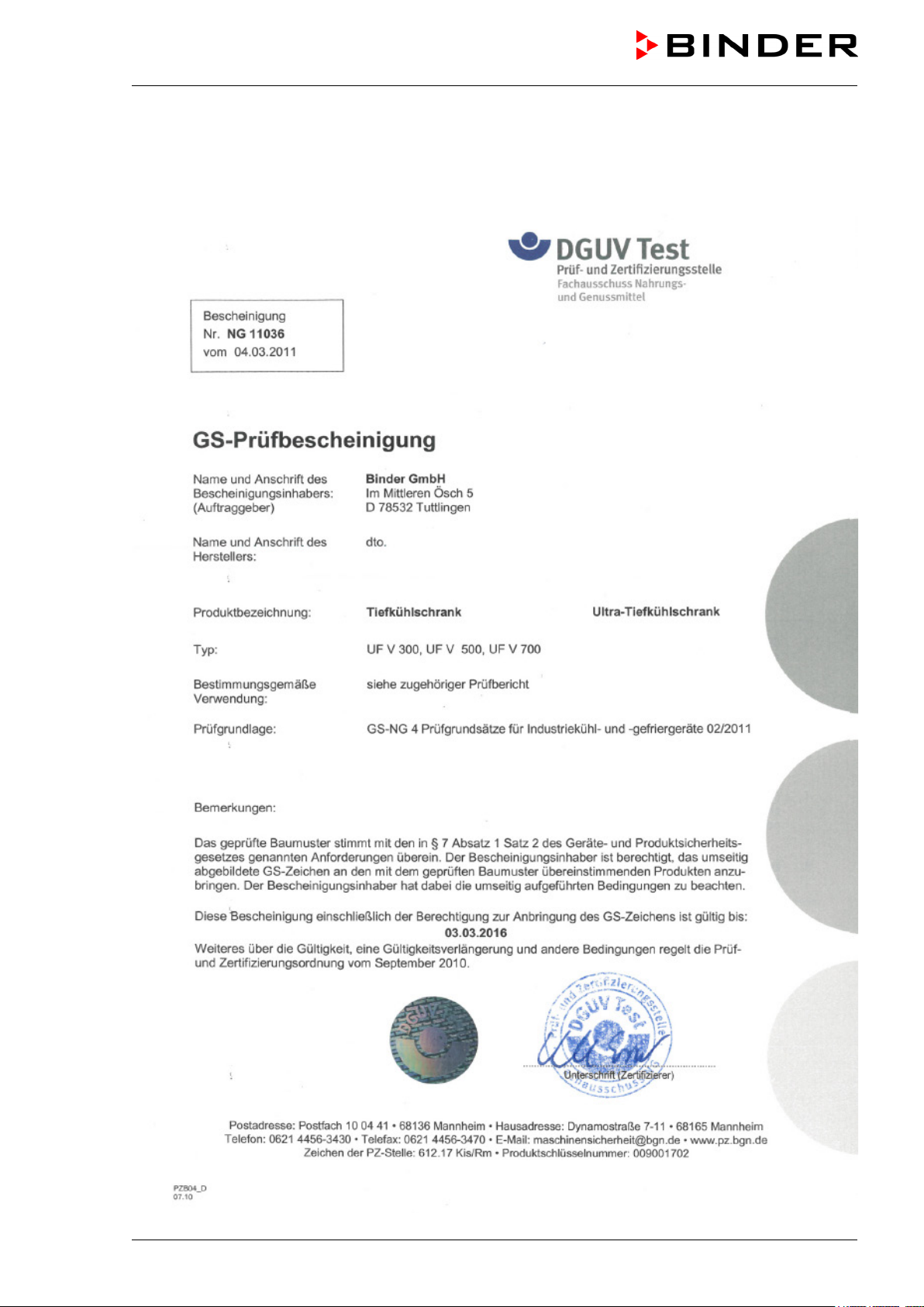
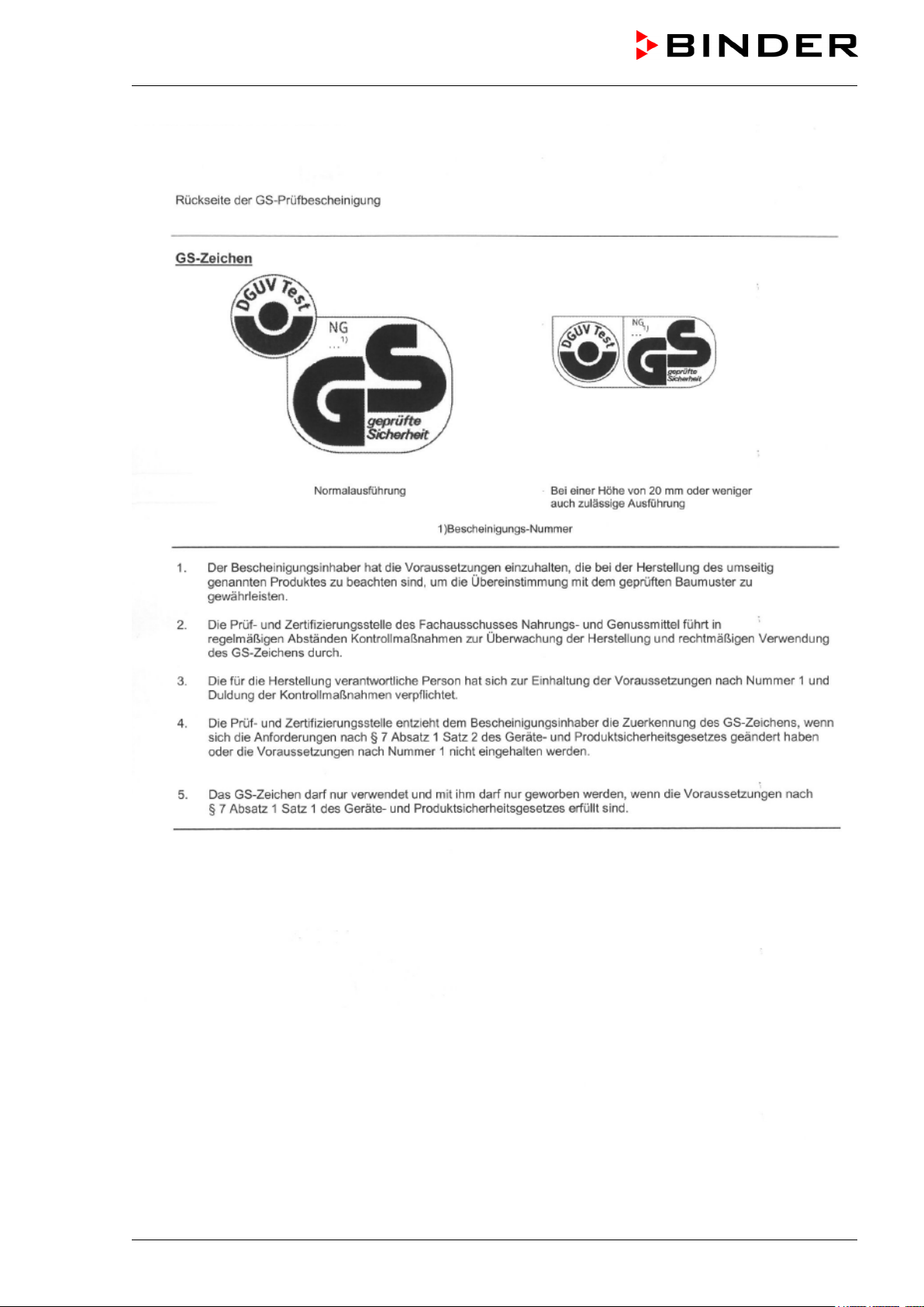
Certificate for the GS mark of conformity of the “Deutsche Gesetzliche Unfallversicherung e.V.“ (German Social Accident Insurance) DGUV
Note: When mounting the optional CO2 emergency cooling, the GS mark is no longer valid
UF V (E2+E2.1) 03/2013 page 5/112
Page 6
UF V (E2+E2.1) 03/2013 page 6/112
Page 7
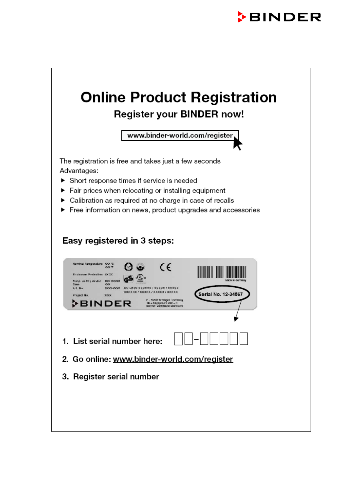
Product registration
UF V (E2+E2.1) 03/2013 page 7/112
Page 8

Contents
EC – declaration of conformity ...................................................................................................................... 2
Certificate for the GS mark of conformity of the “Deutsche Gesetzliche Unfallversicherung e.V.“
(German Social Accident Insurance) DGUV ....................................................................................... 5
Product registration ....................................................................................................................................... 7
1. SAFETY ................................................................................................................ 11
1.1 Legal considerations ......................................................................................................................... 11
1.2 Structure of the safety instructions .................................................................................................... 11
1.2.1 Signal word panel ........................................................................................................................ 11
1.2.2 Safety alert symbol ...................................................................................................................... 12
1.2.3 Pictograms ................................................................................................................................... 12
1.2.4 Word message panel structure .................................................................................................... 13
1.3 Localization / position of safety labels at the unit .............................................................................. 13
1.4 Type plate ......................................................................................................................................... 14
1.5 General safety instructions on installing and operating the UF V freezer ........................................ 15
1.6 Intended use ..................................................................................................................................... 17
1.7 Operating instructions ....................................................................................................................... 17
1.8 Measures to prevent accidents ......................................................................................................... 18
2. UNIT DESCRIPTION ............................................................................................ 19
2.1 Unit overview ..................................................................................................................................... 21
2.2 Housing of the automatic door mechanism with operator panel ...................................................... 23
2.3 Key switch (main power switch) ........................................................................................................ 24
2.4 RP1 controller ................................................................................................................................... 25
2.5 Connection panel on the unit rear ..................................................................................................... 26
2.6 Unit doors .......................................................................................................................................... 27
2.6.1 Outer door .................................................................................................................................... 27
2.6.2 Compartment doors ..................................................................................................................... 27
2.6.3 Emergency release of the outer door .......................................................................................... 27
2.7 Drain well for condensate during defrosting (option) ........................................................................ 29
3. COMPLETENESS OF DELIVERY, TRANSPORTATION, STORAGE, AND
INSTALLATION .................................................................................................... 30
3.1 Unpacking, and checking equipment and completeness of delivery ................................................ 30
3.2 Guidelines for safe lifting and transportation .................................................................................... 31
3.2.1 Moving the freezer inside a building ............................................................................................ 31
3.2.2 Transport outside a building ........................................................................................................ 32
3.3 Storage .............................................................................................................................................. 33
3.4 Location of installation and ambient conditions ................................................................................ 33
3.5 Adjusting the vertically adjustable castors ........................................................................................ 34
4. INSTALLATION AND CONNECTIONS................................................................ 36
4.1 Operating instructions ....................................................................................................................... 36
4.2 Spacers for rear wall distance ........................................................................................................... 36
4.3 Fixing to achieve earthquake safety (optional) ................................................................................. 37
4.4 10 mm access port prepared to be finalized by the user (UF V (E2.1), UF V-UL (E2.1)) ................ 38
4.5 Adjustable shelves ............................................................................................................................ 39
4.6 Electrical connection ......................................................................................................................... 41
4.7 Advanced voltage booster (regular with UF V UL, option for UF V)) ................................................ 41
5. START UP ............................................................................................................ 42
5.1 Preset factory parameters ................................................................................................................. 42
5.2 Operating the automatic door mechanism ........................................................................................ 42
5.3 Door locking with key (option for UF V UL) ....................................................................................... 43
UF V (E2+E2.1) 03/2013 page 8/112
Page 9

5.4
GUARD.CONTROL: RFID personal access control of the automatic door mechanism
(standard for UF V, option for UF V UL) ........................................................................................... 44
5.4.1 Indication of the door condition .................................................................................................... 44
5.4.2 Overview of LED indications of the RFID personal access control ............................................. 45
5.4.3 Cards for access control .............................................................................................................. 45
5.4.4 Operating the RFID access control .............................................................................................. 46
5.4.5 Reading out the door opening data with the GUARD.CONTROL Reader Kit
(Art. no. 8012-0789) ..................................................................................................................... 47
5.4.6 Resetting the entire system ......................................................................................................... 47
5.5 Behavior after turning on the unit ...................................................................................................... 48
6. SETTING THE TEMPERATURE SET POINT AT THE CONTROLLER RP1 ....... 49
7. PLACING SAMPLES IN STORAGE IN THE FREEZER ...................................... 50
8. CONTROLLER RP1 OPERATING MODES ......................................................... 51
8.1 Selecting and setting the operating functions ................................................................................... 51
8.2 Operating mode HAND ..................................................................................................................... 52
8.3 Operating mode USER: Advanced settings ...................................................................................... 53
8.4 Operating mode LOCK: Locking/unlocking of the operating functions’ settings by operating mode
HAND ................................................................................................................................................ 57
8.4.1 Locking the operating functions of operating mode HAND ......................................................... 57
8.4.2 Temporally unlocking the operating functions of operating mode HAND .................................... 57
8.4.3 Permanently unlocking the operating functions of operating mode HAND ................................. 58
8.5 Performance during and after power failure and shut down ............................................................. 58
9. SAFETY CONTROLLER (TEMPERATURE SAFETY DEVICE) .......................... 59
9.1.1 Setting the safety controller set point ........................................................................................... 59
10. INDICATIONS AND ALARM FUNCTIONS (AUTO-DIAGNOSTIC SYSTEM) ..... 61
10.1 Indications and alarm functions overview ......................................................................................... 61
10.2 Resetting the alarm messages ......................................................................................................... 61
10.3 Safety controller temperature alarm.................................................................................................. 62
10.4 Temperature tolerance range alarm (too high and too low temperature) ......................................... 63
10.5 Door open alarm ............................................................................................................................... 64
10.6 Messages from the battery management system ............................................................................. 65
10.7 Power failure alarm ........................................................................................................................... 67
10.8 Temperature sensor failure ............................................................................................................... 68
10.9 Further error messages .................................................................................................................... 69
10.10 Zero-voltage relay alarm output ........................................................................................................ 70
11. CO2 EMERGENCY COOLING (OPTION) ............................................................ 71
11.1 Connecting and exchanging the CO2 pressure cylinder ................................................................... 72
11.2 Operating the CO2 emergency cooling system ................................................................................. 73
11.3 Alarm messages ............................................................................................................................... 75
12. DATA MONITORING AND RECORDING ............................................................ 77
12.1 Ethernet interface (option) ................................................................................................................ 77
12.2 Communication software APT-COM™ 3 DataControlSystem (option) ............................................ 77
12.3 Analog output for temperature .......................................................................................................... 77
12.4 Additional Pt 100 temperature sensor (option) with output to Lemo socket ..................................... 78
12.5 Circular chart recorder (option) ......................................................................................................... 78
12.6 Data logger (standard with UF V UL, option for UF V) ..................................................................... 79
12.7 BINDER GSM Box for remote alarms (option) ................................................................................. 79
13. UNIT INVENTORY AND ACCESSORIES ............................................................ 80
13.1 Storage rack systems (option) .......................................................................................................... 80
13.1.1 Side access racks ........................................................................................................................ 80
13.1.2 Sliding drawer racks ..................................................................................................................... 80
UF V (E2+E2.1) 03/2013 page 9/112
Page 10

13.1.3
Cryo boxes and dividers .............................................................................................................. 81
13.1.4 Cardboard dividers for cryo boxes ............................................................................................... 81
13.1.5 Polypropylene cryo boxes with dividers and codification, transparent ........................................ 81
14. MAINTENANCE, CLEANING, AND SERVICE .................................................... 82
14.1 Immediate aid, service ...................................................................................................................... 82
14.2 Maintenance intervals, service .......................................................................................................... 82
14.3 Cleaning and decontamination ......................................................................................................... 83
14.3.1 Cleaning ....................................................................................................................................... 83
14.3.2 Decontamination .......................................................................................................................... 84
14.4 Maintenance work by the customer .................................................................................................. 86
14.4.1 Checking and cleaning the condenser air filter ............................................................................ 86
14.4.2 Cleaning the condenser ............................................................................................................... 87
14.4.3 De-icing and defrosting ................................................................................................................ 87
14.5 Sending the unit back to BINDER GmbH ......................................................................................... 88
15. DISPOSAL............................................................................................................ 88
15.1 Disposal of the transport packing ..................................................................................................... 88
15.2 Decommissioning .............................................................................................................................. 89
15.3 Disposal of the unit in the Federal Republic of Germany ................................................................. 89
15.4 Disposal of the unit in the member states of the EC except for the Federal Republic of Germany . 90
15.5 Disposal of the unit in non-member states of the EC ....................................................................... 91
16. TROUBLESHOOTING ......................................................................................... 92
17. OVERVIEW OF ALL CONTROLLER INDICATIONS ........................................... 94
17.1 Indications of setting menus ............................................................................................................. 94
17.2 Information and alarm messages...................................................................................................... 95
18. TECHNICAL DESCRIPTION ................................................................................ 97
18.1 Factory calibration and adjustment ................................................................................................... 97
18.2 Over current protection ..................................................................................................................... 97
18.3 Battery replacement .......................................................................................................................... 97
18.4 UF V (E2 / E2.1) technical data ........................................................................................................ 98
18.5 Equipment ....................................................................................................................................... 100
18.6 Optional equipment, accessories and spare parts ......................................................................... 101
18.7 Dimensions UF V 500 (E2) ............................................................................................................. 104
18.8 Dimensions UF V 500 (E2.1) .......................................................................................................... 105
18.9 Dimensions UF V 700 (E2.1) .......................................................................................................... 106
19. CONTAMINATION CLEARANCE CERTIFICATE ............................................. 107
19.1 For units located outside North America and Central America....................................................... 107
19.2 For units in North America and Central America ............................................................................ 110
UF V (E2+E2.1) 03/2013 page 10/112
Page 11
Dear Customer,
For the correct operation of the ULTRA.Guard™ ultra-low temperature freezer UF V, it is important that
you read this operating manual completely and carefully and observe all instructions as indicated. Failure
to read, understand and follow the instructions may result in personal injury. It can also lead to damage to
the unit and/or poor equipment performance.
1. Safety
This operating manual is part of the components of delivery. Always keep it handy for reference.
The freezer should only be operated by laboratory personnel especially trained for this purpose and famil-
iar with all precautionary measures required for working in a laboratory. To avoid injury and damage observe the safety instructions in the operating manual.
WARNING
Failure to observe the safety instructions.
Serious injuries and unit damage.
Observe the safety instructions in this operating manual
Carefully read the complete operating instructions for the ultra-low temperature freezer.
1.1 Legal considerations
This operating manual is for informational purposes only. It contains information for installing, start-up,
operation and maintenance of the product. Note: the contents and the product described are subject to
change without notice.
Understanding and observing the instructions in this operating manual are prerequisites for hazard-free
use and safety during operation and maintenance. In no event shall BINDER be held liable for any damages, direct or incidental arising out of or related to the use of this manual.
This operating manual cannot cover all conceivable applications. If you would like additional information,
or if special problems arise that are not sufficiently addressed in this manual, please ask your dealer or
contact us directly by phone at the number located on page one of this manual
Furthermore, we emphasize that the contents of this operating manual are not part of an earlier or existing agreement, description, or legal relationship, nor do they modify such a relationship. All obligations on
the part of BINDER derive from the respective purchase contract, which also contains the entire and exclusively valid statement of warranty administration. The statements in this manual neither augment nor
restrict the contractual warranty provisions.
1.2 Structure of the safety instructions
In this operating manual, the following safety definitions and symbols indicate dangerous situations in
accordance with the standards ISO 3864-2 and ANSI Z535.6.
1.2.1 Signal word panel
Depending on the probability of serious consequences, potential dangers are identified with a signal
word, the corresponding safety color, and if appropriate, the safety alert symbol.
DANGER
Indicates an imminently hazardous situation that, if not avoided, will result in death or serious (irreversible) injury.
UF V (E2+E2.1) 03/2013 page 11/112
Page 12
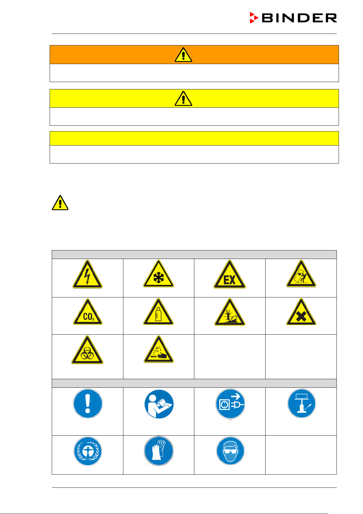
Warning signs
Electrical hazard
Explosive atmosphere
Pollution Hazard
or chemical burns
Mandatory action signs
plug
Environment protection
Wear protective gloves
WARNING
Indicates a potentially hazardous situation which, if not avoided, could result in death or serious
(irreversible) injury
CAUTION
Indicates a potentially hazardous situation which, if not avoided, may result in moderate or minor
(reversible) injury
CAUTION
Indicates a potentially hazardous situation, which, if not avoided, may result in damage to the product
and/or its functions or to property in its proximity.
1.2.2 Safety alert symbol
Use of the safety alert symbol indicates a risk of injury.
Observe all measures that are marked with the safety alert symbol in order to avoid death or
injury.
1.2.3 Pictograms
suffocation hazard
CO
2
Biohazard
Very cold surface
Gas cylinders
Risk of corrosion and /
Stability hazard
Harmful substances
Mandatory regulation
UF V (E2+E2.1) 03/2013 page 12/112
Read operating
instructions
Disconnect the power
Wear safety goggles
Lift with mechanical
assistance
Page 13

Prohibition signs
water
Pictograms (Warning signs)
Service label
Figure 1: Position of labels
Do NOT touch
Do NOT spray with
Information to be observed in order to ensure optimum function of the product.
Do NOT climb
1.2.4 Word message panel structure
Type / cause of hazard.
Possible consequences.
∅ Instruction on how to avoid the hazard: prohibition
Instruction on how to avoid the hazard: mandatory action
Observe all other notes and information not necessarily emphasized in the same way, in order to avoid
disruptions that could result in direct or indirect injury or property damage.
1.3 Localization / position of safety labels at the unit
The following labels are located on the unit:
Very cold surface
on the freezer UF V 700 (E2.1)
Replace safety labels that are no longer legible. Contact BINDER Service for these replacements.
UF V (E2+E2.1) 03/2013 page 13/112
Keep safety labels complete and legible.
Page 14
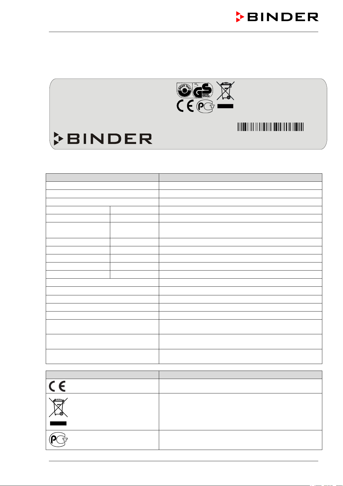
Indications of the type plate (example)
Information
BINDER
Manufacturer: BINDER GmbH
UF V 500
Model UF V 500
ULTRA.GUARD ULT Freezer
“ULTRA.GUARD” ultra-low temperature freezer
Serial No.
00-00000
Serial No. 00-00000
Built
2011
Year of construction 2011 (example)
Nominal temperature
-86 °C
-123°F
Enclosure protection
IP 20
IP type of protection 20 acc. to EN 60529
Temp. safety device
DIN 12880
Temperature safety device acc. to standard DIN 12880
Class
---
(Class of temperature safety device)
Art. No.
9020-0236
Art. No. 9020-0236
Project No.
---
(Special application acc. to project no.)
1.10 kW
Nominal power 1.10 kW
230 V 1 N ~
Nominal voltage 230 V ± 10 %, single-phase unit
4.8 A
Nominal current 4.8 Amp
50 Hz
Power frequency 50 Hz
Max. operating pressure 28 bar
Max operating pressure 28 bar in the refrigerating system
Stage 1 R 404A – 0,365 kg
Refrigerant for cooling 1st stage: R 404A, filling weight: 0.365
kg
Stage 2 R 508B – 0,35 kg
Refrigerant for cooling 2nd stage: R 508B, filling weight: 0.350
kg
Contains fluorinated greenhouse gases
covered by the Kyoto Protocol.
Contains fluorinated greenhouse gases covered by the Kyoto
Protocol
Symbol on the type plate
Information
Nominal temperature
-86°C
1.10 kW
Max. operating pressure 28 bar
-123°F
230 V 1 N ~
Stage 1: R 404 A - 0,365 kg
Enclosure protection
Temp. safety device
IP 20
DIN 12880
4,8 A
50 Hz
Stage 2: R 508 B - 0,35 kg
Contains fluorinated greenhouse gases
Class
covered by the Kyoto Protocol.
Art. No.
9020-0236
GS mark not valid with mounted
Built
2011
ULTRA.GUARD ULT Freezer
D 78532 Tuttlingen / Germany
Internet: www.binder-world.com
E2.1 Made in Germany
1.4 Type plate
The type plate sticks to the left side of the unit, bottom right-hand.
Project No.
option CO2 emergency cooling
Tel. + 49 (0) 7462/ 2005-0
UF V 500 Serial No. 00-00000
Figure 2: Type plate (example UF V 500 (E2.1) standard unit)
Nominal temperature
UF V (E2+E2.1) 03/2013 page 14/112
CE conformity marking
Electrical and electronic equipment manufactured / placed on
the market in the EC after 13 August 2005 and to be disposed of in a separate collection according to directive
2002/96/EC on waste electrical and electronic equipment
(WEEE).
The equipment is certified in the GOST R certification system
of GOSTSTANDARD Russia.
Page 15

Symbol on the type plate
Information
LABORATORY EQUIPMENT
43KM
CAUTION
GS mark of conformity of the “Deutsche Gesetzliche Unfallversicherung e.V. (DGUV), Fachausschuss Nahrungs- und Genussmit-
GS mark not valid with mounted
option CO
emergency cooling
2
tel, Prüf- und Zertifizierungsstelle im DGUV Test“ (German Social
Accident Insurance (DGUV), Expert Committee for the food processing industry, Testing and Certification Body in DGUV). When
mounting the optional CO
emergency cooling, the GS mark of
2
conformity is no longer valid.
(UL units only)
The equipment is certified by Underwriters Laboratories Inc.
cording to standards CAN/CSA-C22.2 No. 61010-1, 2
2004-07 (Electrical Equipment for Measurement, Control, and
Laboratory Use; Part 1: General Requirements); UL 61010-1, 2
nd
Edition,
®
ac-
nd
Edition, 2005-07-22 (Electrical Equipment for Measurement, Control, and Laboratory Use; Part 1: General Requirements)
1.5 General safety instructions on installing and operating the UF V freezer
With regard to operating the freezer and to the installation location, please observe the guideline
BGI/GUV-I 850-0 on safe working in laboratories (formerly BGR/GUV-R 120 or ZH 1/119 laboratory
guidelines issued by the employers’ liability insurance association) (for Germany).
BINDER GmbH is only responsible for the safety features of the unit provided skilled electricians or qualified personnel authorized by BINDER perform all maintenance and repair, and if components relating to
chamber safety are replaced in the event of failure with original spare parts.
To operate the unit, use only original BINDER accessories or accessories from third-party suppliers authorized by BINDER. The user is responsible for any risk caused by using unauthorized accessories.
CAUTION
Danger of overheating.
Damage to the unit.
∅ Do NOT install the unit in unventilated recesses.
Ensure sufficient ventilation of the installation site for dispersal of the heat.
Leakage of refrigerant in the event of a unit defect.
Danger to the environment.
Ensure sufficient ventilation of the installation site.
Do not operate the freezer in hazardous locations.
DANGER
UF V (E2+E2.1) 03/2013 page 15/112
Explosion hazard.
Danger of death.
∅ Do NOT operate the unit in potentially explosive areas.
∅ KEEP explosive dust or air-solvent mixtures AWAY from the unit.
Page 16

The freezer does not does not dispose of any measures of explosion protection.
DANGER
Explosion hazard.
Danger of death.
∅ Do NOT introduce any substance into the freezer which is combustible or explosive at
working temperature.
∅ NO explosive dust or air-solvent mixture in the inner chamber.
Any solvent contained in the charging material must not be explosive or inflammable. I.e., irrespective of
the solvent concentration in the steam room, NO explosive mixture with air must form. The temperature
inside the chamber must lie below the flash point or below the sublimation point of the charging material.
Familiarize yourself with the physical and chemical properties of the charging material.
Familiarize yourself with any potential health risks caused by the charging material. Take adequate
measures to exclude any risk prior to putting the freezer into operation.
WARNING
Contamination with toxic, infectious or radioactive substances.
Danger of intoxication.
Danger of infection.
Protect the interior of the unit against contamination by toxic, infectious or radioactive
substances.
Take appropriate measures when bringing in or taking out toxic, infectious or radioac-
tive substances.
DANGER
Electrical hazard.
Danger of death.
∅ The unit must NOT become wet during operation or maintenance.
The freezers were produced in accordance with VDE regulations and were routinely tested in accordance
to VDE 0411-1 (IEC 61010-1).
CAUTION
The inner surfaces become very cold during operation.
Danger of injury by freezing on.
∅ Do NOT directly touch the inner surfaces or the charging material during operation.
∅ AVOID skin contact with the inner surfaces and accessory equipment.
Wear protective gloves when opening the inner doors and during manipulation.
UF V (E2+E2.1) 03/2013 page 16/112
Page 17
WARNING
Stability hazard.
Danger of injury.
Damage to the unit and the charging material.
Housing cover breakaway.
∅ Do NOT climb on the lower housing cover.
∅ Do NOT load the lower housing cover with heavy objects while the unit door is open.
1.6 Intended use
ULTRA.Guard™ ultra-low temperature freezers UF V are technical equipment and intended solely for use
at work. They are suitable are designed for safe storage of varied materials at temperatures up to –86 °C
/ -122,8 °F, especially for long-term storage of biological, medical, and chemical samples at constant low
temperature. They are suitable for the domains Pharmacy, Medicine, Life Sciences, plastic industry, electronic components, food etc.
Freezers are designed for storage of harmless materials. None of the components of the charging material must be able to form an explosive mixture with air.
Following the instructions in this operating manual and conducting regular maintenance work
(chap. 14) are part of the intended use.
Other applications are not approved.
WARNING: If customer should use a freezer running in non-supervised continuous operation, we strongly recommend in case of inclusion of irrecoverable specimen or samples to
split such specimen or samples and store them in at least two chambers, if this is feasible.
1.7 Operating instructions
Depending on the application and location of the unit, the operator of the freezer must provide the relevant information for safe operation of the unit in a set of operating instructions.
Keep these operating instructions with the unit at all times in a place where they are clearly
visible. They must be comprehensible and written in the language of the employees.
UF V (E2+E2.1) 03/2013 page 17/112
Page 18
1.8 Measures to prevent accidents
The operator of the ULTRA.Guard™ ultra-low temperature freezer UF V must observe the following regulation: Occupational Safety Regulations. Operation of refrigeration units, heat pumps and cooling systems
(GUV-R 500 chap. 2.35) (for Germany).
Following measures have been taken by the manufacturer in order to prevent ignition and explosions:
• Indications of the type plate
See operating manual chap. 1.4
• Operating manual
An operating manual is available for each freezer.
• Temperature monitoring
The freezer has a temperature display which can be read from outside.
An additional temperature safety device is built into the device. A visual and an audible signal (buzzer)
show exceeding of the temperature.
• Safety, measurement and control devices
The safety, measuring, and control devices are easily accessible.
• Electrostatic charge
The interior parts are grounded.
• Protection against touchable surfaces
Tested according to EN ISO 13732-3:2008.
• Floors
See operating manual chap. 3.4 for installation
• Cleaning
See operating manual chap. 14.3.
• Examinations
The freezer has been inspected by the “Deutsche Gesetzliche Unfallversicherung e.V. (DGUV), Fachausschuss Nahrungs- und Genussmittel, Prüf- und Zertifizierungsstelle im DGUV Test“ (German
Social Accident Insurance (DGUV), Expert Committee for the food processing industry, Testing and
Certification Body in DGUV) and bears the GS mark.
The GS mark is omitted if the chamber is equipped with the optional CO2 emergeny cooling.
UF V (E2+E2.1) 03/2013 page 18/112
Page 19

2. Unit description
The ULTRA.Guard™ ultra-low temperature freezers UF V were produced with great care using the latest
tools for development and production. They were optimized for safe long-term storage of samples in the
ultra-low temperature range and reach the minimum temperature of -86 °C / -122.8 °F in approx. 9 hours.
You can operate the freezer in a temperature range from -86 °C / -122.8 °F up to -40 °C / -40 °F.
The UF V units are regularly equipped with the progressive RFID system (optional for UF V UL), offering
personalized access control. The UF V UL units are regularly equipped with the advanced voltage booster AVC (option for UF V) and a data logger (option for UF V).
The freezers are available with the door hinged on right or left and for several different voltages.
Easy opening and closing door mechanism and access control
A pushbutton permits opening the automatic door mechanism without using your hands. A pull-tight function automatically closes the outer door when slightly open. For personalized access control, the freezer
door is RFID controlled (standard with UF V, option for UF V UL) and an optional door locking with key is
available (option for UF V UL).
The freezer is regularly equipped with a key switch (main power switch) to switch on and off the unit.
Controller
For temperature control, the freezer is equipped with the microprocessor controller RP1 with a digital
display. The controller keypad can be locked (keyboard locking). Temperature setting is accurate to one
degree. The controller is mounted at eye level.
The controller offers an error diagnostics system generating audible and visual warning and alarm messages. During power failure, alarm function and control remain active during 72h. The controller provides
password protection for the setting menus. Testing the alarm functions is always possible.
The controller monitors ambient temperature and issues an alarm if it exceeds an adjustable value.
A counter of operating hours / weeks is included.
Housing
The inner chamber and the inside of the insulated outer door are made of stainless steel (material no.
1.4301 (V2A) in Germany). The housing is RAL 7035 powder-coated. All corners and edges are also
completely coated. The inner surfaces are smooth and therefore easy to clean. Easy front access permits
filter cleaning without tools. A 10 mm access port prepared to be finalized by the user and an additional
optional access port serves to introduce a cable and sensor of a measuring device.
The buildup of ice in the door area is minimal due to perfect closing of the inner and outer doors and a
heating of the outer door gasket. Precise spatial distribution of the cold in the interior ensures storage of
all samples at an identical storage temperature. The prevention of thermal bridges protects against defrosting. The combination of vacuum insulation panels (V technology) and CFC-free polyurethane foaming maximizes the cold storage capacity.
The freezer has four compartment doors. You can insert stainless steel shelves are make optimum use of
the interior. You can flexibly arrange the shelves to use the interior in a variable and optimum manner.
Inventory racks (stainless steel storage racks with cryo boxes, chap. 13) are optionally available.
Vertically adjustable castors with locks serve to move the freezer and then place it safely at its destination.
UF V (E2+E2.1) 03/2013 page 19/112
Page 20

Cooling system
The powerful, energy-efficient and low-noise refrigerating machine uses the refrigerants R404a and
R508b. They are completely free of HCFCs (hydrochlorofluorocarbons) and CFCs (chlorofluorocarbon)
and not inflammable.
st
Control of the two-stage refrigerating machine: The 1
nd
stage cooling turns on depending on the temperature.
2
stage cooling immediately turns on. In addition, the
Safety
Thanks to the standard overtemperature safety device, the set temperature is maintained also in case of
a controller failure.
In case of power failure at -80 °C / -112 °F, a temperature of -60 °C / -76 °F will not be exceeded in an
empty freezer for at least 3 hours, in a loaded freezer (measured with a 30 kg / 66 lb water load) for approx. 7 hours.
The freezer is equipped with a rechargeable battery (12 V, 7.2 Ah). Battery voltage is regularly monitored.
An alarm indicates too low battery voltage. You can check battery voltage in the “USER” menu.
The advanced voltage booster provides automatic voltage compensation through a buck/boost converter
(standard with UF V UL, option for UF V, chap. 4.7).
An error diagnostics system monitors the unit functions and generates audible and visual warning and
alarm messages. The door is monitored for being closed.
The CO
emergency cooling (option, chap. 11) offers additional refrigeration, i.e., following introduction of
2
a heat load, in case of a power failure or failure of the cooling system.
Data monitoring and recording
The freezer is regularly equipped with a zero-voltage relay alarm output (chap. 10.10) and with an analog
output (chap. 12.3) for integration into customer systems. An additional independent Pt100 temperature
sensor with output on Lemo socket is available (option, chap. 12.4). The freezer can be optionally
equipped with an Ethernet interface (option, chap. 12.1) for computer communication, enabling monitoring via a network. The BINDER communication software APT-COM™ 3 DataControlSystem (option,
chap. 12.2) permits networking of up to 30 units and connection to a computer, as well as recording and
representing temperature data.
A circular chart recorder (option for UF V UL, chap. 12.5) or a data logger with USB port that is independent from the chamber controller (standard with UF V UL, option for UF V, chap. 12.6) serve to independently record the temperature values, data given out in compliance with FDA guideline 21 CFR part
11.
UF V (E2+E2.1) 03/2013 page 20/112
Page 21

(A)
2.1 Unit overview
(B)
(C)
(D)
(E)
Figure 3: Freezer UF V 700 (E2.1), front view
(A) Outer door
(B) Housing of the automatic door mechanism and controller (description chap. 2.2, for emergency
release see chap. 2.6.3)
(C) Compressor housing
(D) Air filter grille (checking and cleaning the filter chap. 14.4.1)
(E) Vertically adjustable castors (adjustment chap. 3.5)
UF V (E2+E2.1) 03/2013 page 21/112
Page 22

(F)
(G)
(C)
(D)
(F)
(B)
(A)
Figure 4: Freezer UF V 700, with open outer door
(A) Outer door
(B) Housing of the automatic door mechanism and controller (description chap. 2.2, for emergency
release see chap. 2.6.3)
(C) Compressor housing
(D) Air filter grille (checking and cleaning the filter chap. 14.4.1)
(E) Vertically adjustable castors (adjustment chap. 3.5)
(F) Compartment with variable shelf
(G) Compartment door
UF V (E2+E2.1) 03/2013 page 22/112
Page 23
Left unit side
Front view
Left unit side
Front view
(1)
(1)
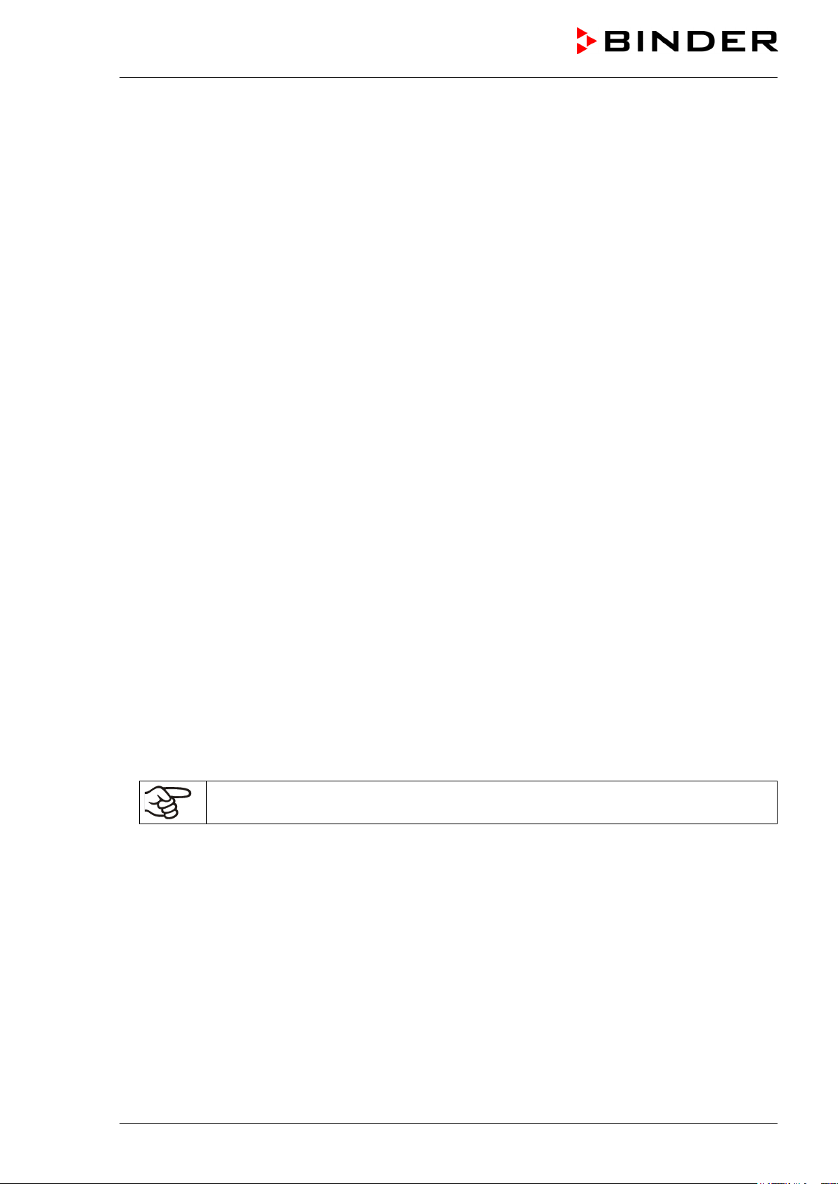
2.2 Housing of the automatic door mechanism with operator panel
(2) (3) (4) (5)
Figure 5: UF V (E2): Housing of automatic door mechanism with emergency release cover, operator pan-
el of controller RP1, RFID control of the automatic door mechanism, and door locking with key (option)
(2) (3) (4) (5)
Figure 6: UF V (E2.1): Housing of automatic door mechanism with emergency release cover, operator
panel of controller RP1, RFID control of the automatic door mechanism, and door locking with key (op-
tion)
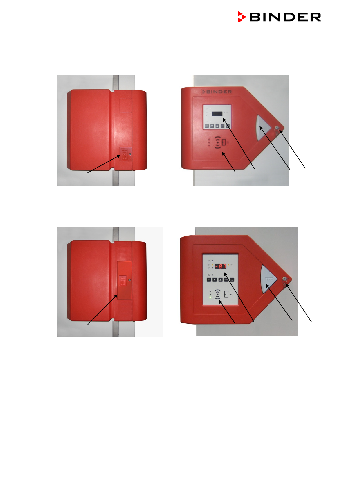
(1) Emergency release cover
(2) GUARD.CONTROL: RFID control of the automatic door mechanism (standard with UF V, option for
UF V UL, chap. 5.4)
(3) Operator panel of controller RP1
(4) Push-button “OPEN” to open the door
(5) Door locking with key (option for UF V UL, chap. 5.3)
UF V (E2+E2.1) 03/2013 page 23/112
Page 24
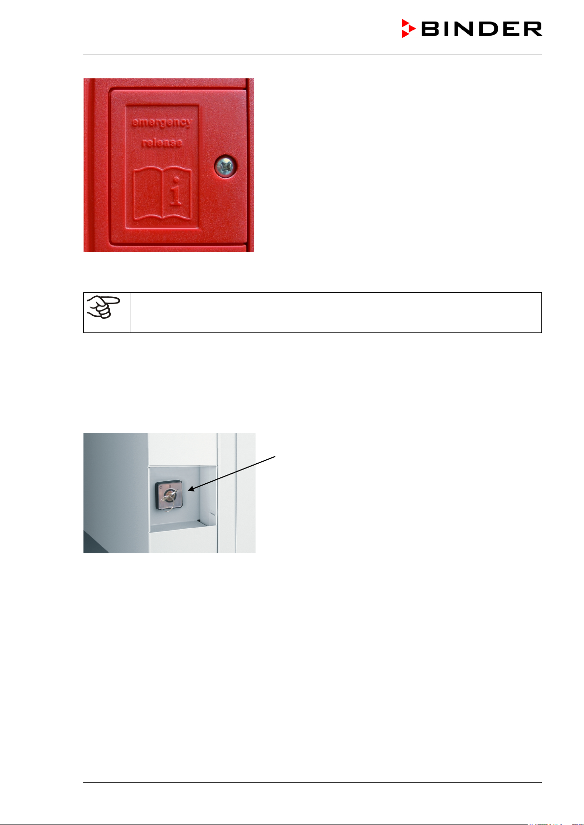
Figure 7: Emergency release cover
Following power connection / turning on the unit or closing the door, you can open the door
again only after approx. 30 seconds. This is to protect the electromechanical door mechanism against damage.
2.3 Key switch (main power switch)
Key switch (6)
Figure 8: Position of the key switch (6) on the right side of
the unit
(6) Key switch (main power switch)
You can remove the key of the key switch (main power switch) in der ON position as well as in the OFF
position.
UF V (E2+E2.1) 03/2013 page 24/112
Page 25
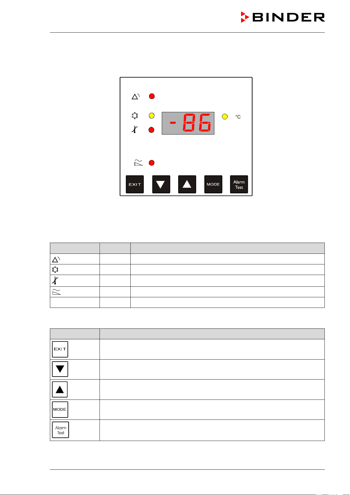
2.4 RP1 controller
The controller RP1 controls the temperature inside the freezer.
Figure 9: Overview controller RP1
Controller alarm and status LEDs
Symbol LED Meaning
red General alarm
yellow Intensive cooling active
red Temperature alarm
red Power failure, no battery connected, battery voltage too low
°C yellow Display of a temperature value in °C
Controller buttons
Button Function
Switch off the alarm sound, reset alarm messages, call up the previous operating
function
Reduce value
Increase value
Confirm entry and call up next operating function
Switching on / off the alarm test (switching on: press down for 5 sec. switching off:
press down briefly)
UF V (E2+E2.1) 03/2013 page 25/112
Page 26
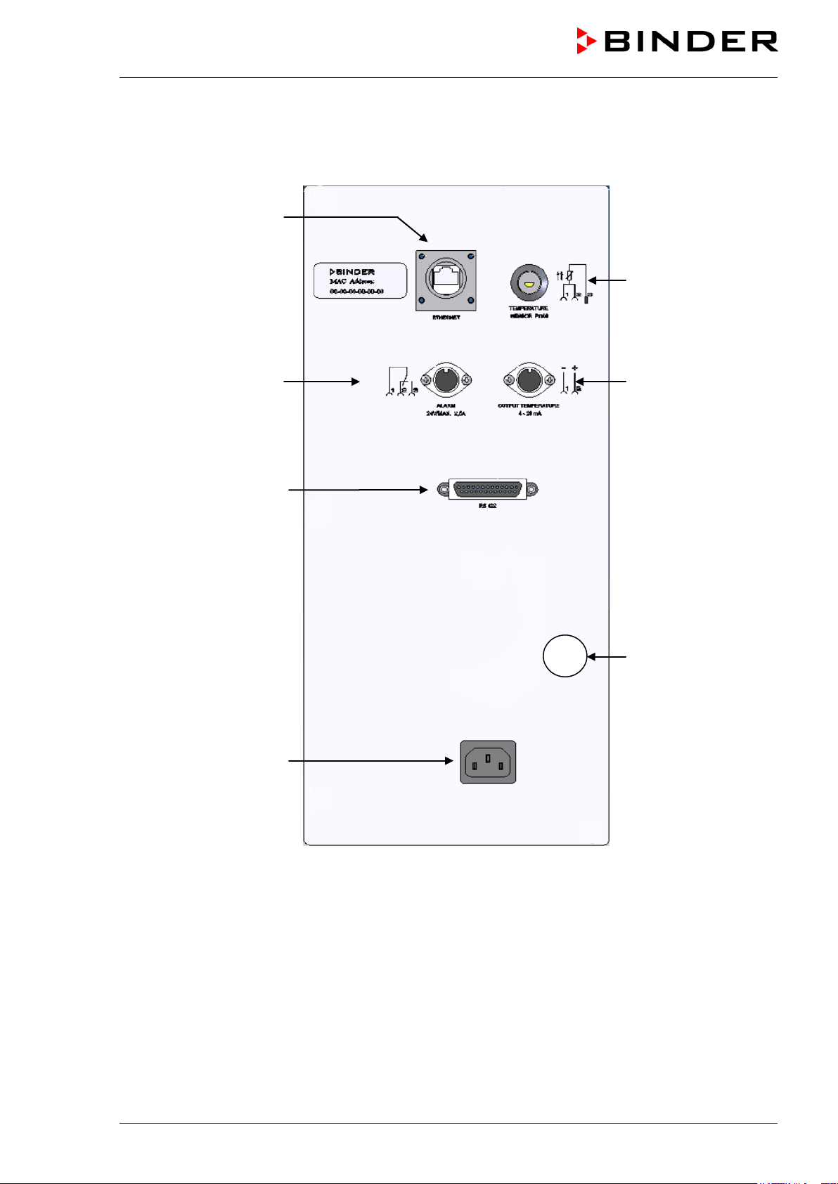
2.5 Connection panel on the unit rear
(7)
(8)
(9)
(11)
(12)
(13)
(10)
Figure 10: Rear connection panel of the freezer UF V (E2 / E2.1)
(7) Ethernet interface for computer communication (option, chap. 12.1)
(8) Connection socket for zero-voltage relay alarm contact (chap. 10.10)
(9) RS 422 interface for computer communication
(10) Connection socket for IEC connector cable with internal locking system
(44) Connection socket for additional Pt 100 temperature sensor (option, chap. 12.4)
(12) Connection socket for analog output 4-20 mA (chap. 12.3)
(13) Connection socket for the electrical connection of the CO
emergency cooling (option, chap. 11)
2
UF V (E2+E2.1) 03/2013 page 26/112
Page 27
2.6 Unit doors
2.6.1 Outer door
The outer gasket of the freezer outer door is heated. The door must be closed while the unit is operating
normally in order to ensure stable conditions in the inner chamber.
You can operate the automatic door mechanism (chap. 5.2) without using your hands:
• Open: Firmly press the push-button “OPEN” e.g. with your elbow
• Close: Firmly press on the door for at least 2 seconds e.g., with your shoulder, until the automatic door
lock is activated and closes the door tightly. The door then pulls tight automatically.
Following power connection / turning on the unit or closing the door, you can open the door
again only after approx. 30 seconds. This is to protect the electromechanical door mechanism against damage.
Delay time for the temperature tolerance range alarm :
After closing the outer door, the tolerance range alarm is switched off for a programmable
delay time. This prevents alarms being constantly triggered during the unstable operating
phase after opening the outer door.
The outer door is available hinged left or right.
DANGER
Risk of locking in a person.
Danger of death.
Before closing doors, make sure that nobody is inside.
Pull the power plug before entering the interior (e.g. for cleaning purposes), thereto pull
the locking button on the plug (Figure 23).
2.6.2 Compartment doors
The freezer interior is divided into in 4 compartments, which are isolated against the surrounding with
doors. This permits bringing in or removing the samples of an individual compartment without remarkably
affect temperature in the other compartments.
The compartment doors remain closed by magnetism when opening the outer door without need for closing them mechanically.
Open the inner doors as shortly as possible to avoid a temperature rise inside the freezer. The maximum
angle of aperture is 90°.
2.6.3 Emergency release of the outer door
In case of power failure or a motor fault, you can open the unit door using the emergency release cover
(1). It is fixed with a cross tip screw.
Following an emergency release, the door can be closed again only by a service technician. Carry out the
emergency release only in emergency and make sure that unfreezing of the samples can be prevented.
UF V (E2+E2.1) 03/2013 page 27/112
Page 28

CAUTION
• Turn off the freezer at its
the locking button on the
to unscrew the Phillips
screw of the Emergency
Remove the emergency
• Use a fork wrench SW8 to
unscrew both screw nuts
A suitable fork wrench is
It is located at a
filter grille (D) behind the
• Remove the lock bolt from
• Now you can open the unit
Danger of destruction of samples.
Carry out the emergency release only in emergency.
Ensure that a service technician is available and/or that the samples can be stored
cold.
Proceeding for emergency release
main power switch and pull
the power plug, thereto pull
plug (Figure 23).
• Use a suitable screwdriver
release cover
•
release cover
(M5).
•
supplied.
magnetic holder inside the
upper edge.
the door
door.
UF V (E2+E2.1) 03/2013 page 28/112
Page 29
After the error has been removed, a service technician can close the door. Please contact BINDER Service.
Note: The freezer offers the possibility of an electrical emergency release, which can be performed by a
qualified technician. Advantage: With the return of the power supply, operation can continue. Contact
BINDER service.
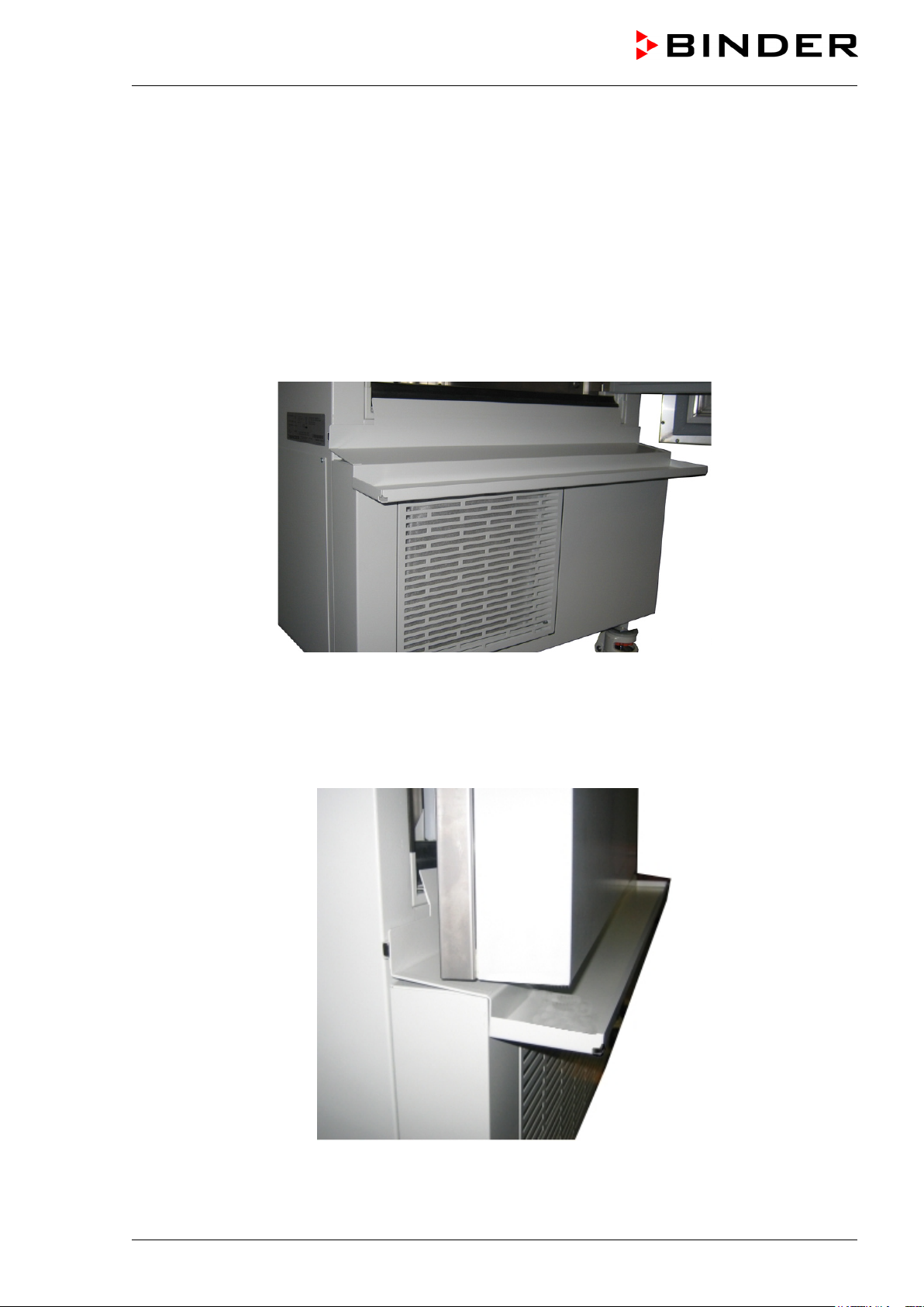
2.7 Drain well for condensate during defrosting (option)
The drain well collects the dripping water when defrosting.
Strong magnets on the drain well sides fix it on the unit.
Attach the drain well to the freezer. Its first level rests on the lower housing panel. The gasket is aligned
to the bottom edge of the freezer interior.
Figure 11: Freezer with drain well (option)
While defrosting use adhesive tape to keep the door above the drain well (drain off position). Now the
melted condensate flows into the drain well.
Place a reservoir below the hole at the front left corner of the drain well, so that the water can drain off.
Figure 12: Unit door in drain off position above the drain well
UF V (E2+E2.1) 03/2013 page 29/112
Page 30
Lift the unit using technical devices (fork lifter) from the pallet. Set the fork lifter laterally
3. Completeness of delivery, transportation, storage, and installa-
tion
3.1 Unpacking, and checking equipment and completeness of delivery
After unpacking, please check the unit and its optional accessories, if any, based on the delivery receipt
for completeness and for transportation damage. Inform the carrier immediately if transportation damage
has occurred.
Caution: The drain well is placed under the unit between the castors. Please remove it before unpacking
the freezer!
CAUTION
Sliding or tilting of the unit.
Damage to the unit.
∅ Do NOT lift the unit using the door, the housing of the automatic door mechanism or
the lower housing.
∅ Do NOT lift the unit by hand.
∅ Do NOT transport the unit horizontally.
Keep the unit in upright position. Max. angle of inclination during transport: 10°.
or from the rear in the middle of the unit. Make sure to place all the lateral supports of
the unit on the forks (check: the fork protrudes at the opposite unit side).
Wear suitable shoes (safety shoes).
The final tests of the manufacturer may cause traces of the shelves on the inner surfaces. This has no
impact on the function and performance of the unit.
Please remove any transportation protection devices and adhesives in/on the unit and on the doors and
remove the operating manuals and accessory equipment.
Remove any protective lamination sheet on the inner metal surfaces prior to commissioning.
Wait at least 8 hours following transport with technical devices (chap. 3.2.2) before start-up.
If you need to return the unit, please use the original packing and observe the guidelines for safe lifting
and transportation (chap. 3.2).
For disposal of the transport packing, see chap. 15.1.
Scope of delivery
• Ultra-low temperature freezer UF V
• 2 keys for the main power switch (key switch)
• 3 shelves,12 shelf holders and 3 fixing plates with screws
• DIN plug for the zero-voltage relay alarm output
• Starter set RFID cards (master card, switch-off card, 3 user cards) (standard with UF V, option for
UF V UL)
• Data logger (standard with UF V UL, option for UF V)
• 2 spacers for rear wall distance.
• Operating manual
UF V (E2+E2.1) 03/2013 page 30/112
Page 31

CAUTION
Note on second-hand units (Ex-Demo-Units)
Second-hand units are units that have been used for a short time for tests or exhibitions. They are thoroughly tested before resale. BINDER ensures that the chamber is technically sound and will work flawlessly.
Second-hand units are marked with a sticker on the unit door. Please remove the sticker before commissioning the unit.
3.2 Guidelines for safe lifting and transportation
3.2.1 Moving the freezer inside a building
Before moving the freezer the castor locks must be raised completely (moving position, chap. 3.5).
The castors are designed only for moving the freezer inside a building. This is possible only on a floor
without joints (e.g. no tiles) and when avoiding shocks. In this case, the freezer must not be empty (max.
load see technical data, chap. 18.4).
If you want to move the unit across a large door threshold or into an elevator to change the floor, empty
the freezer and put all shelves on the bottom of the interior.
If you incline the unit by less than 5°, you can directly turn it on after moving (at least 10 minutes after
turning off). Otherwise, wait at least 8 hours until putting it into operation again.
As soon as the unit has reached its destination, completely let down the castor locks (operating position,
chap. 3.5) in order to be able to permanently support the unit’s weight.
Wear suitable shoes (safety shoes) when moving the freezer.
Over very short distances (within reach of the power cable), you can move the freezer while operating.
If you turned off the unit (turning off at the main power switch, pulling the power plug), wait at least 10
minutes after moving until you turn on again the unit in order to protect the refrigeration machine against
damage.
Too quick restart of the refrigeration machine.
Damage to the unit.
After turning off wait 10 minutes before turning on the freezer again.
UF V (E2+E2.1) 03/2013 page 31/112
Page 32

890 mm
900 mm
1400 mm
1315 mm
To move the freezer through narrow passages (doors, narrow corridors), open the unit door:
Figure 13: UF V 700 with open unit door
For transport outside a building use technical equipment (chap. 3.2.2).
3.2.2 Transport outside a building
Before moving the freezer you can raise the castor locks completely (moving position, chap. 3.5). The
castors are designed only for moving the freezer inside a building (respect the information given in chap.
3.2.1).
We recommend letting down completely the castor locks prior to transport in order to protect the unit
against unintentional rolling.
After operation, please observe the guidelines for temporarily decommissioning the unit (chap. 15.2).
CAUTION
Sliding or tilting the unit.
Damage to the unit.
∅ Do NOT lift or transport the unit using the door, the housing of the automatic door
mechanism or the lower housing.
∅ Do NOT lift the unit by hand
∅ Do NOT transport the unit horizontally.
Transport the unit only in its original packaging.
Secure the freezer with transport straps for transport.
Keep the unit in upright position. Max. angle of inclination during transport: 10°.
Place the shelves on top of each other on the bottom of the interior.
Lift the unit using technical devices (fork lifter) and place it on the transport pallet. Set
the fork lifter laterally or from the rear in the middle of the unit. Make sure to place all
the lateral supports of the unit on the forks (check: the fork protrudes at the opposite
unit side).
Transport units ONLY with the original transport pallet. Set the fork lifter only to the
pallet. Without the pallet the unit is in imminent danger of overturning
Wear suitable shoes (safety shoes).
UF V (E2+E2.1) 03/2013 page 32/112
Page 33

CAUTION
• Permissible ambient temperature range for transport: -10 °C / 14°F to +60 °C / 140°F.
You can order transport packing and rolling pallets for transportation purposes from BINDER Service.
Freezer transport in upright position is mandatory in order to avoid oil running out of the engine casing
and resulting damages to the cooling system. Max. angle of inclination during transport: 10°.
Wear suitable shoes (safety shoes) during transport.
Following transport, wait at least 8 hours until start-up.
3.3 Storage
Intermediate storage of the unit is possible in a closed and dry room. Observe the guidelines for temporary decommissioning (chap. 15.2).
• Permissible ambient temperature range for storage: -10 °C / 14°F to +60 °C / 140°F.
• Permissible ambient humidity: max. 70% r.H., non-condensing
Secure the unit against unintentional rolling by letting down the front castor locks (chap. 3.5).
When after storage in a cold location you transfer the unit to its warmer installation site, condensation
may form in the inner chamber or on the housing. Before start-up, wait at least one hour until the freezer
has attained ambient temperature and is completely dry. According to the type of transport that has taken
place (chap. 3.2) you may have to wait at least 8 hours until start up.
3.4 Location of installation and ambient conditions
The freezer is designed for setting up inside a building (indoor use). Set up the freezer on a flat, even
surface, free from vibration and in a well-ventilated, dry location. Let down the vertically adjustable castors (operating position, chap. 3.5) and align the unit using a spirit level. The site of installation must be
capable of supporting the unit’s weight (see technical data, chap. 18.4).
CAUTION
Danger of overheating.
Damage to the unit.
∅ Do NOT set up units in non-ventilated recesses.
Ensure sufficient ventilation for dispersal of the heat.
Leakage of refrigerant in the event of a unit defect.
Danger to the environment.
Ensure sufficient ventilation of the installation site.
• Permissible ambient temperature range for operation: +18 °C / 64.4 °F to +32 °C / 89.6 °F. At elevated
ambient temperature values, fluctuations in temperature can occur.
The ambient temperature should not be substantially higher than the indicated ambient temperature of +25 °C / 77 °F to which the specified technical data relate. For other ambient conditions, deviations from the indicated data are possible.
Prevent the freezer from sucking warm air from other devices.
UF V (E2+E2.1) 03/2013 page 33/112
Page 34

Avoid direct solar radiation on the unit. Do not place the freezer in direct vicinity of units with a
high heat emission.
• Permissible ambient humidity: 70% r.H. max., non-condensing.
• Installation height: max. 2000 m / 6561.7 ft above sea level.
Minimum distances:
• between several units: 250 mm / 9.84 in
• Wall distance, rear: 100 mm / 3.94 in (spacer is supplied, see chap. 4.2)
• Wall distance, laterally, on the side without door hinge: 100 mm / 3.94 in
• Wall distance, laterally, on the side with door hinge: 240 mm / 9.45 in.
• Spacing above the unit: 100 mm / 3.94 in
Ventilation openings must not be blocked. Ensure a distance of at least 100 mm / 3.94 in to the ventilation
openings on the freezer’s front and rear.
To completely separate the unit from the power supply, you must disconnect the power plug.
Install the unit in a way that the power plug is easily accessible and can be easily pulled in
case of danger. To disconnect the connector plug, simultaneously pull the locking button
(Figure 23).
With an increased amount of dust in the ambient air, clean the condenser fan (by suction or blowing)
several times a year. Check the condenser air filter frequently and clean it if necessary (chap. 14.4.1).
Avoid any conductive dust in the ambiance according to the unit layout complying with pollution degree 2
(IEC 61010-1).
Do not install or operate the freezer in potentially explosive areas.
DANGER
Explosion hazard.
Danger of death.
∅ Do NOT operate the unit in potentially explosive areas.
∅ KEEP explosive dust or air-solvent mixtures AWAY from the vicinity of the unit.
3.5 Adjusting the vertically adjustable castors
The vertically adjustable castors with locks serve to block the castors and to set up the unit at level (operating position).
For transport raise the castor locks completely (moving position, live ring leftwards) to achieve maximum
ground clearance. For setting up, let them down (operating position, turn live ring rightwards, Figure 14).
UF V (E2+E2.1) 03/2013 page 34/112
Page 35

Moving position
Operating position
Figure 15: Adjusting the castor locks
Figure 16: Adjusting the castor locks
Figure 14: Letting down the castor locks
As soon as the castor locks have ground contact, turning becomes tight. You can use a screwdriver
(Figure 15) or set a fork wrench size 13 below the live ring (Figure 16).
with a screwdriver
with a fork wrench
The castors are designed only for moving the freezer inside a building (chap. 3.2.1). For transport outside
a building use technical equipment (chap. 3.2.2).
Wear suitable shoes (safety shoes) when moving the freezer or during transport.
The castor locks must be let down completely in order to be able to permanently support the
complete load (max. load see technical data, chap. 18.4).
Align the unit using a spirit level placed on the inner chamber bottom.
UF V (E2+E2.1) 03/2013 page 35/112
Page 36

Figure 17: Spacer for rear wall distance
Figure 18: Rear UF V 700 with mounted spacers
4. Installation and connections
4.1 Operating instructions
Depending on the application and location of the unit, the operator of the freezer must provide the relevant information for safe operation of the unit in a set of operating instructions.
Keep these operating instructions with the unit at all times in a place where they are clearly
visible. They must be comprehensible and written in the language of the employees.
4.2 Spacers for rear wall distance
Please fix both spacers with the delivered screws at the unit rear. This serves to ensure the prescribed
minimum distance to the rear wall of 100 mm / 3.94 in.
UF V (E2+E2.1) 03/2013 page 36/112
Page 37

4.3 Fixing to achieve earthquake safety (optional)
Two slots on the freezer’s rear provide fastening lugs. You can mount a chain or rod to fix the unit at the
wall.
Figure 19: Slots on the freezer’s rear to mount a fixing device
UF V (E2+E2.1) 03/2013 page 37/112
Page 38

4.4 10 mm access port prepared to be finalized by the user (UF V (E2.1), UF V-
UL (E2.1))
The UF V (E2.1) is equipped with an access port to be finalized by the user for cables with a diameter of
up to 10 mm. When finalizing this access port the freezer should be approx. at room temperature.
CAUTION
Works inside the UF V with low inside temperature.
Danger of injury by freezing on.
Turn off the freezer prior to finalizing the access port an let it warm up until approx.
room temperature.
To finalize the access port proceed as follows:
• Break out the pre-punched rectangle in the rear wall (Figure 20) with suitable pliers
• Break out the pre-punched rectangle in the inner chamber (Figure 21) with suitable pliers
• Use a screwdriver to pierce the PU foam insulation horizontally from the inside
• Pass the desired cables through the port
• Use the sealing kit (art. no. 8009-0815) for sealing. The included insulation tube is to close the
remaining free space after passing the cables. Thoroughly seal both openings of the port with the
sealant. This avoids the entry of humidity from the ambient air into the insulation.
Figure 20: Rear view UF V (E2.1) with pre-punched access port
Figure 21: Inner chamber UF V (E2.1) with pre-punched access port
UF V (E2+E2.1) 03/2013 page 38/112
Page 39

• Use a 4 mm Allen wrench to fix the screws of the shelf holder bar
4.5 Adjustable shelves
The scope of delivery comprises three adjustable shelves. You can mount them and further optional
shelves in different positions of the lateral walls in 24 mm / 1 inch steps. In standard position, the shelves
are placed with a distance of 310mm / 12.2 in, forming the bottom of the compartments, thus making
available the maximum space for optional inventory systems.
When using the optional shelves for operation at -40 °C / -40 °F, leave a free space of 8 cm each on the
left and right side when introducing the load.
To remove a shelf, lift and incline it, then pull it forward.
It is required to fix the adjustable shelves in order to avoid that
a person could be locked in the freezer. For this purpose,
mount the supplied fixing plates as described below for each
side:
Figure 22: Fixing plate
• Use a 4 mm Allen wrench to loosen
the screws of the shelf holder bar
• Put the fixing plate below the shelf
holder bar
• Screw the fixing plate to the shelf
UF V (E2+E2.1) 03/2013 page 39/112
Page 40

Unit size
500
700
Permitted load of individual shelf (regular)
kg / lbs
50 / 110
65 / 143
Permitted total load of all shelves (regular)
kg / lbs
200 / 441
260 / 573
Permitted load of individual optional shelf (for operation at -40 °C)
kg / lbs
30 / 66
30 / 66
Permitted total load of all optional shelves (for operation at -40 °C)
kg / lbs
120 / 265
120 / 265
For optimal use of space, we recommend the following shelf positions:
Position of 3 shelves to obtain 4
compartments with equal ceiling
height
Position of 4 shelves (1 x optional)
to obtain 5 compartments with
equal ceiling height
Position of 3 shelves to obtain the
maximum sample storage space: 2
compartments with a ceiling height
of 334 mm / 13.15 in (for racks
4x6) and 2 compartments with a
ceiling height of 279 mm / 11 in (for
racks 4x4)
Insert the shelf holders into the
following positions of the shelf
holder bar (starting from the bottom):
13, 25, 37
Insert the shelf holders into the
following positions of the shelf
holder bar (starting from the bottom):
10, 20, 30, 40
Permitted shelf loads:
UF V (E2+E2.1) 03/2013 page 40/112
Insert the shelf holders into the
following positions of the shelf
holder bar (starting from the bottom):
14, 25, 38
Page 41

Power connection
cable
Power plug
Voltage
+/-10 %
Current
type
Power
frequency
Fuse
Fixed power connection
Fixed power connection
4.6 Electrical connection
An internal overload release protects the freezer against excess-current.
UF V
UF V UL
(115 V)
UF V UL
(208-240 V)
• Prior to connection and start-up, check the power supply voltage. Compare the values to the specified
data located on the unit’s type plate (located on the left-hand side of the unit, bottom right-hand, chap.
1.4)
• Observe a sufficient current protection according to the number of freezers that you want to operate.
• When connecting, please observe the regulations specified by the local electricity supply company
and as well as the VDE directives (for Germany)
• Pollution degree (acc. to IEC 61010-1): 2
• Over-voltage category (acc. to IEC 61010-1): II
IEC connector plug and
cable 2000 mm
cable 1800 mm
cable 1800 mm
shockproof
plug
NEMA 5-20P 115 V 1N~ 60 Hz 16 A
NEMA 6-20P 208 - 240 V 2~ 60 Hz 10 A
230 V 1N~ 50 Hz 10 A
CAUTION
Danger of incorrect power supply voltage.
Damage to the equipment.
Check the power supply voltage before connection and start-up.
Compare the power supply voltage with the data indicated on the type plate.
See also electrical data (chap. 18.4).
To completely separate the unit from the power supply, you must disconnect the power plug.
Install the unit in a way that the power plug is easily accessible and can be easily pulled in
case of danger. To disconnect the connector plug, simultaneously pull the locking button
(Figure 23).
• When connecting to power supply pay attention to properly grounding it.
To disconnect the connector plug, simultaneously pull the red locking button on the plug in the arrow
direction.
Figure 23: IEC connector plug with internal locking system
4.7 Advanced voltage booster (regular with UF V UL, option for UF V))
With this option, a buck/boost converter automatically compensates for voltage fluctuation.
UF V (E2+E2.1) 03/2013 page 41/112
Page 42

Check that the interior of the freezer is empty. Prior to starting a new freezer
5. Start up
Following transport, wait at least 8 hours until start-up.
or if you do not know what the freezer was last used for, for hygiene purposes you should clean and disinfect the interior (chap.
After connecting the supply lines, turn on the unit by the key switch (6) setting it to position 1).
Figure 24: Key switch (position ON)
5.1 Preset factory parameters
The unit is supplied with the following preset parameters:
14.3).
Temperature set point -80 °C / -112 °F
Safety controller
The maximum permitted deviation from the temperature set point for
tolerance range alarm
Delay time tolerance range alarm temperature after closing the door 60 min
Password to lock / unlock the HAND operating functions 0 (no locking)
Password to access operating mode USER 1
Set point type “Limit”
-60 °C / -76 °F
6 K
5.2 Operating the automatic door mechanism
Opening the door:
Firmly press the one-touch pushbutton “OPEN”. You can now open
the door.
Closing the door:
Firmly press on the door for at least 2 seconds until the automatic
door mechanism is activated and closes the door tightly.
UF V (E2+E2.1) 03/2013 page 42/112
After turning on the freezer, you can open the door after 30 seconds only.
Following closing the door, you can open the door again only after approx. 30 seconds due to
necessary venting.
Figure 25: Pushbutton “OPEN” to
open the door
Page 43

Automatic door mechanism
Automatic door mechanism
Automatic door mechanism
locked
DANGER
Risk of locking in a person.
Danger of death.
Before closing doors, make sure that nobody is inside.
Pull the power plug before entering the interior (e.g. for cleaning purposes) , thereto
pull the locking button on the plug (Figure 23).
5.3 Door locking with key (option for UF V UL)
With this option, use a key to operate the door locking (5). In locked condition, the automatic door mechanism is locked, i.e., pushbutton “OPEN” which serves to open the door has no effect.
Automatic door mechanism accessible Switch position to the right
Automatic door mechanism locked: Switch position vertical
Only in locked condition, you can remove the key.
accessible
Figure 26: Positions of key with door locking option
locked
accessible
Figure 27: Symbols of the door locking (option)
locked
UF V (E2+E2.1) 03/2013 page 43/112
Page 44

5.4 GUARD.CONTROL: RFID personal access control of the automatic door
mechanism (standard for UF V, option for UF V UL)
GUARD.CONTROL secures the access to the freezer. There is additional logging of the opening events
in an access protocol, which contains time, date and duration of the opening and the identification of the
user card that had been used.
Access authorization is controlled by means of the supplied access cards. Hold these cards in front of the
RFID area in the housing of the door mechanism and controller (max. distance 5 cm / 2 inches).
UF V (E2) UF V (E2.1)
Figure 28: RFID panel for access control of the automatic door mechanism
and indication of the door condition
5.4.1 Indication of the door condition
The blue LED indicates the door condition:
off Door open or closed. You can open or close the door.
lit
flashing slowly Door opening or closing
flashing fast
Waiting time of 30 Sec. after closing the door or power connection / turning on
the freezer
Control error. Contact BINDER Service
or
Mechanical obstruction of the door. Remove icing in the door area or other
cause.
If you do not close the door within one minute after opening, a continuous audible signal keeps sounding
until closing the door.
Only when the blue LED is off, you can open or close the door.
UF V (E2+E2.1) 03/2013 page 44/112
Page 45

lit
lit
lit
lit
lit
lit
5.4.2 Overview of LED indications of the RFID personal access control
The red, yellow, and green LEDs indicate the respective RFID control function when using the access
cards.
Initial state (RFID inactive). When the blue LED is off, open the door with
pushbutton “OPEN”.
Normal mode (Master card registered, RFID active)
Switch-off mode (RFID inactive). When the blue LED is off, open the door
with pushbutton “OPEN”.
or
Opening mode (user card acknowledged, RFID active). Open the door with
pushbutton “OPEN”.
User card refused
flashing 2 sec.
Learning mode (individual user card can be registered or cleared)
User card registration
flashing 2 sec.
flashing 2 sec.
An individual user card is being cleared
flashing 2 sec.
Clearing mode (all user cards can be cleared)
flashing 2 sec.
All user cards are being cleared
5.4.3 Cards for access control
With each freezer unit, a master card, a switch-off card and 3 user cards (scope of delivery) are available
for access control. The system can memorize up to 60 user cards. The cards have a copy protection
related to their internal card number.
The user cards serve to open the freezer. The user cards release the automatic door mechanism on
condition that the card number was registered in the system by means of the master card. You can open
the door with pushbutton “OPEN”.
The master card serves to registering / clearing the card numbers in the system. A master card will not
open the chamber. In case of having lost the master card, the system can be reset to initial state with a
service unit and a code exchange with BINDER Service.
The switch-off card serves to inactivate the RFID access control. Using the switch-off card is possible
only together with the registered master card.
UF V (E2+E2.1) 03/2013 page 45/112
Page 46

5.4.4 Operating the RFID access control
In the initial state (i.e. no access card has been registered), RFID access control is inactive, i.e., you can
open the door with pushbutton “OPEN”.
Opening the door in the initial state
Initial state (green LED is lit)
RFID access control is inactive
⇒ Open the door with pushbutton “OPEN”.
Registering the master card in the Initial state
Initial state (green LED is lit)
⇒ Hold the master card in front of the RFID panel. Card registration takes place.
Normal mode (yellow LED is lit)
Registering / clearing of an individual user card
Normal mode (yellow LED is lit)
⇒ Hold the master card briefly (< 2 seconds) in front of the RFID panel.
Learning mode (yellow LED flashes)
⇒ Hold the user card in front of the RFID panel.
• New card: card registration takes place (green LED flashes for 2 seconds)
• Already registered card: card is cleared (red LED flashes for 2 seconds)
• No action during 3 seconds: Learning mode is cancelled
Back to normal mode (yellow LED is lit)
Opening the door with a user card
Normal mode (yellow LED is lit)
⇒ Hold the master card in front of the RFID panel
• Registered card: Door can be opened during 30 sec. (green LED is lit during possible opening)
• New card: Door cannot be opened (red LED is lit for 2 seconds)
Back to normal mode (yellow LED is lit)
Clearing all user cards
Normal mode (yellow LED is lit)
⇒ Hold the master card briefly (< 2 seconds) in front of the RFID panel.
Learning mode (yellow LED flashes)
⇒ Hold the master card > 3 seconds in front of the RFID panel.
Clearing mode (red LED is lit for 2 seconds)
⇒ Hold the master card within 2 seconds again in front of the RFID panel: All user cards are being de-
leted (red LED flashes)
• Master card not held again within 2 seconds in front of the RFID panel: Clearing mode is can-
celled
Back to normal mode (yellow LED is lit)
UF V (E2+E2.1) 03/2013 page 46/112
Page 47

Switching off the RFID access control
Normal mode (yellow LED is lit)
⇒ Hold the master card briefly (< 2 seconds) in front of the RFID panel.
Learning mode (yellow LED flashes)
⇒ Hold the switch-off card in front of the RFID panel.
Switch-off mode (yellow and green LED are lit). RFID access control is inactive. Open the door with
pushbutton “OPEN”.
Switching on again the RFID access control
Switch-off mode (yellow and green LED are lit)
⇒ Hold the master card < 2 seconds in front of the RFID panel.
Learning mode (yellow LED flashes)
After 3 seconds back to normal mode (yellow LED is lit)
5.4.5 Reading out the door opening data with the GUARD.CONTROL Reader Kit (Art. no.
8012-0789)
Place the GUARD.CONTROL Reader in front of the RFID area to have the door opening data transferred
to the reader. You can then connect the reader to a computer. Data is collected and stored in the computer using the GUARD.CONTROL software. Without a PC connection the GUARD.CONTROL Reader
can read up to 10 devices (data sets). A single data set of a freezer contains the ID of the door lock (device number and name) and 10.000 events maximum (storage capacity of the UF V door lock). If this
number of events is exceeded, the new events overwrite the oldest events in the door lock. An event
contains a time stamp and the performed action, if appropriate with the card ID (user number).
5.4.6 Resetting the entire system
In case of having lost the master card, BINDER Service can reset the system to initial state together with
the operator of the freezer. Please contact BINDER Service.
UF V (E2+E2.1) 03/2013 page 47/112
Page 48

5.5 Behavior after turning on the unit
During the equilibration phase of 9 hours after turning on the unit, undefined temperature conditions occur within the unit. During this phase, do not place any sample materials in the unit
CAUTION
Danger of destruction of samples.
Load the freezer only after equilibration of temperature.
Following turning on the unit with the key switch (6), there is a subsequent brief startup phase in which
the display items at the edges of the controller display light up successively.
After a few seconds, the display shows the current interior temperature of the freezer. The lit LED at the
right of the display shows that the temperature is displayed in °C.
Figure 29: Normal display of controller after turning on the
freezer, showing the current temperature value: 15 °C (example)
Set the controller to the desired temperature set point (chap. 6) used to operate the freezer.
As long as there is a difference between the actual and set value shown in the display, the
intended operation of the unit will not be ensured.
UF V (E2+E2.1) 03/2013 page 48/112
Page 49

: Entry of temperature
6. Setting the temperature set point at the controller RP1
Figure 30: Normal Display
Confirm the entry with the “MODE” key.
After 30 seconds the controller reverts to Normal Display automatically.
The yellow LED
Only insert samples into the freezer when it has reached its stable operating state.
indicates operation of the 2nd stage cooling.
Current temperature value: -70 °C
Figure 31
set point with arrow keys.
Temperature set-point: -80 °C
Temperature equilibrating time to -80 °C / -112 °F is approx. 5 hours (UF V 500) / approx. 9 hours (UF V
700).
UF V (E2+E2.1) 03/2013 page 49/112
Page 50

7. Placing samples in storage in the freezer
Before storing valuable samples, conduct a 10-days test run at the desired temperature. This helps to
detect transport damages like capillary cracks. Then you can load the freezer with the precooled samples.
WARNING: If customer should use a freezer running in non-supervised continuous operation, we strongly recommend in case of inclusion of irrecoverable specimen or samples to
split such specimen or samples and store them in at least two chambers, if this is feasible.
During the equilibration phase of 9 hours after turning on the unit, undefined temperature conditions occur within the unit. During this phase, do not place any sample materials in the unit
CAUTION
Danger of samples being destroyed.
Load the freezer only after equilibration of temperature.
When placing not precooled samples in storage, temperature rises inside the freezer. We recommend to
successively load the freezer. The more thermal energy you bring in, the longer it takes until reaching the
set-point temperature again.
Do not exceed the maximum load of each compartment and the permitted total load (see chap.18.4).
Always wear protective gloves when opening the freezer and bringing in or removing material.
CAUTION
The inner surfaces become very cold during operation.
Danger of injury by freezing on.
∅ Do NOT directly touch the inner surfaces or the charging material during operation.
∅ AVOID skin contact with the inner surfaces and accessory equipment.
Wear protective gloves when opening the inner doors and during manipulation.
UF V (E2+E2.1) 03/2013 page 50/112
Page 51

8. Controller RP1 operating modes
The controller provides three operating modes HAND (chap. 8.2), USER (chap. 8.3), and LOCK (chap.
8.4). In operating modes HAND and USER, you can call up several operating functions and set / modify
their values.
Operating mode USER is password protected. On delivery, the password is set to “1” (factory setting).
You can change the password in operating function “PA.U” (chap. 8.3).
You can also implement password protection for operating mode HAND (chap. 8.4).
8.1 Selecting and setting the operating functions
The controller's display shows the operating function (e.g. “SP” = temperature set point) and alternately
the associated value (e.g. -86).
When the displayed value is the temperature in °C, the yellow LED “°C” to the right of the display lights
up.
Figure 32: Controller display
when setting operating functions, here: setting of temperature set point
“MODE” key:
• In operating modes HAND and USER, access the next operating function by pressing “MODE”.
• In the same time, pressing “MODE” confirms the changed value of the current operating function, i.e.,
the freezer will from now on regulate at the new value.
If you do not want to accept the modification of a value, wait 30 seconds without pressing any
button or press the “EXIT” button. The controller reverts to Normal Display automatically without accepting the modification.
To go back to the Normal display, press “MODE” repeatedly.
“EXIT” key:
• In operating modes HAND and USER, go back to the previous operating function by pressing “EXIT”.
Arrow keys:
Use “▲” or “▼” to change the value of the selected operating function or to select between defined values.
In some operating functions, you can read but not change the value (for service and maintenance purposes).
If a button for 30 seconds is not pressed after access to an operating function or changing a value, the
controller toggles back to Normal display automatically. If the “MODE” button is not pressed after changing a value in the displayed operating function, the value reverts to its previous value.
UF V (E2+E2.1) 03/2013 page 51/112
Page 52

Temperature set point
8.2 Operating mode HAND
• In Normal display, press button “MODE” to toggle to operating mode HAND.
• Use the “MODE” button to successively call up the operating functions.
• Use “▲” or “▼” to set the values of the operating functions.
Operating functions that can be set in operating mode HAND
Display Setting range Operating function
-90 °C to -40 °C
-70 °C to -20 °C
Set-point entry of CO
(only with option CO
emergency cooling
2
emergency cooling “On”)
2
Safety controller set point when set point type is “Limit” (Lit)
-86 °C to -40 °C
Limit value, i.e., maximum permitted absolute temperature value. When
exceeded, the safety controller triggers an alarm. Set the limit value by
approx. 15 K above the controller temperature set point.
Indication of supply voltage (only with option Advanced voltage booster)
Max. 3-digit numeric password for locking/unlocking the operating function setting in operating mode LOCK (chap. 8.4)
0 to 999
To permit temporary unlocking: select any password other than 0.
To permit permanent unlocking: set password to “0”.
Set the safety controller each time the set point for the temperature is changed. Set the safety
controller set point by approx. 15 K above the controller temperature set point.
UF V (E2+E2.1) 03/2013 page 52/112
Page 53

8.3 Operating mode USER: Advanced settings
• In Normal display, press “EXIT” and “MODE” simultaneously for 3 seconds to access the options for
selecting the operating modes of the freezer.
Figure 33: Selecting the operating mode
• Press “▲” or “▼” until the value “O P. U ” (operating mode USER) appears in the display.
• Press “MODE”. The display to enter the password appears.
The operating mode USER is password-protected by a number. The password is preset to "1" in factory.
You can change the password in operating function “PA.U”.
Figure 34: Password request
• Use “▲” or “▼” to enter the password and press “MODE”.
• Use the “MODE” key to successively call up the operating functions. Use the “EXIT” key to go back to
the previous operating function.
• Use “▲” or “▼”to set the values of the operating functions.
This menu also offers activating and inactivating the CO
emergency cooling (option, chap. 11):
2
UF V (E2+E2.1) 03/2013 page 53/112
Page 54

Operating functions in operating mode USER:
Display Setting range Operating function
-90 °C to -40 °C
Temperature set-point
On OFF
Release of CO
Switch on or off CO
emergency cooling
2
emergency cooling
2
-70 °C to -20 °C
Set-point entry of CO
(only with option CO
emergency cooling
2
emergency cooling “On”)
2
On
Switch on the test of CO
(only with option CO
emergency cooling
2
emergency cooling “On”)
2
The function automatically turns off after 10 seconds.
-90 °C to -40 °C
0 °C to 50 °C
On OFF
0 to 999
Safety controller set point (Limit value)
Limit value, i.e., maximum permitted absolute temperature value. When
exceeded, the safety controller triggers an alarm. Set the limit value by
approx. 15 K above the controller temperature set point.
Setting of ambient temperature alarm (factory setting 33 °C)
Switch on or off ambient temperature alarm
Indication of supply voltage (only with option Advanced voltage boost-
er)
Max. 3-digit numeric password for locking/unlocking the operating function setting in operating mode LOCK (chap. 8.4)
To permit temporary unlocking: select any password other than 0.
To permit permanent unlocking: set password to “0”.
UF V (E2+E2.1) 03/2013 page 54/112
Page 55

Display Setting range Operating function
0 to 999
1 to 254
Password setting for access to operating mode USER
Remember the modified password or you will no longer be able to access
operating mode USER.
Setting the unit address.
Addressing serves for data transfer e.g. via the communication software
APT-COM™ 3 DataControlSystem. Do not change standard setting “1”.
Firmware revision of main controller for service / maintenance purposes.
Firmware revision of safety controller for service / maintenance purposes.
Data record (year) for service / maintenance purposes.
0 to 999
0 to 168
Data record (month) for service / maintenance purposes.
Data record (day) for service / maintenance purposes.
Data set version for service / maintenance purposes.
Counter of operating weeks
Counter of operating hours, up to one week
UF V (E2+E2.1) 03/2013 page 55/112
Page 56

Display Setting range Operating function
Indication of battery voltage
Indication of temperature value of cooling system, for service /
maintenance purposes
Indication of temperature value of cooling system, for service /
maintenance purposes
Indication of temperature value of cooling system, for service /
maintenance purposes
Indication of temperature value of cooling system, for service /
maintenance purposes
UF V (E2+E2.1) 03/2013 page 56/112
Page 57

: Display when trying to enter a setting in Operating mode
8.4 Operating mode LOCK: Locking/unlocking of the operating functions’ set-
tings by operating mode HAND
To avoid operating functions being changed by unauthorized persons, you can lock the operating functions’ settings.
8.4.1 Locking the operating functions of operating mode HAND
• In operating mode HAND, define a maximum 3-digit numeric password in operating function “PA.H”.
• Wait 30 seconds. The controller returns to Normal display. Setting the operating functions in operating
mode HAND is now locked.
• When trying to enter a setting, the message “loc” appears on the controller. After 30 seconds the controller returns to Normal display
Figure 35
LOCK, i.e. with blocked operating functions’ settings
8.4.2 Temporally unlocking the operating functions of operating mode HAND
• In Normal display, press “EXIT” and “MODE” simultaneously for 3 seconds to access the operating
mode selection. “OP. L ” (operating mode LOCK) is displayed.
The menu “OP.L” (operating mode LOCK) is only visible if a password has previously been
defined in the operating function “PA.H” in the operating mode HAND.
• Press “▼”or “▼” to enter operating mode HAND. “O P. H ” (operating mode HAND) is displayed.
• Press “MODE”. The menu to enter the password is displayed.
Figure 36: Password request
• Enter the password using the “▲” or “▼”keys.
• Confirm the entry with “MODE”. The controller returns to Normal display.
If you have selected any password other than zero, operating mode HAND is temporarily unlocked.
Changing the operating functions in operating mode HAND is now possible until a period of 30 sec. has
passed with no activity. 30 seconds after the last keypad entry, the operating functions are relocked.
UF V (E2+E2.1) 03/2013 page 57/112
Page 58

Display Setting range Operating function
Password request
0 to 999
Entry of the password that has been defined in operating mode HAND in
operating function “PA.H” (chap. 8.2). The operating functions’ settings in
operating mode HAND are temporarily unlocked.
8.4.3 Permanently unlocking the operating functions of operating mode HAND
To permanently unlock the settings, set operating function “PA.H” to “0” in HAND mode (chap. 8.2).
8.5 Performance during and after power failure and shut down
In the event of power failure, the battery maintains the controller functions. The controller display is dark
and can be activated for 5 seconds by pressing any button. The refrigerating machine is out of operation..
The unit’s refrigerating function can be maintained through the optional CO2 emergency cooling (chap.
11). The zero-voltage relay alarm output (8) (chap. 10.10) is switched for the whole duration of the power
failure.
After the power returns, each freezer turns on with an individual firmly assigned delay of max. 180 sec-
onds to prevent current spikes in the customer's electricity supply system by simultaneously switching on
several devices.
The controller counts down the time until restart in seconds.
Figure 37: Time until restart
After the power returns or when turned on by hand, the freezer regulates the temperature to the last entered set point.
All settings and set point values remain in the memory during power failure after power off.
UF V (E2+E2.1) 03/2013 page 58/112
Page 59

9. Safety controller (temperature safety device)
The freezer is equipped with an over temperature safety device. It is designated as the “safety controller”.
This second, electrically independent temperature controller takes over control at a selectable set point in
case of fault. It serves to protect the charging material against excessively high temperatures.
The message “otc” on the controller display indicates safety controller activity. The red collective alarm
LED
the “EXIT” button switches off the audible alarm. The safety controller regulates the freezer at the entered
safety controller set point until the temperature inside the freezer returns below this temperature. Then
the alarm message “otc” and the LEDs
The safety controller set point is a limit value, i.e. the absolute maximum permitted temperature value.
Example: temperature set point -86 °C / -122.8°F, safety controller set point -60 °C / -76 °F.
flashes, the LED “ ” is lit. At the same time there is an additional audible alert (buzzer).Pressing
and “ ” go off.
Regularly check the safety controller setting. Set the safety controller set point by approx. 10
°C above the desired temperature set point.
The settings of the safety controller are inactive during battery operation, open door, power
failure, CO
power supply and/or the restart of the unit with the key switch (6).
emergency cooling (option). They become functional again following restitution of
2
9.1.1 Setting the safety controller set point
You can check and set the safety controller set point in operating modes HAND (chap. 8.2) or USER
(chap. 8.3).
• In operating modes HAND and USER, operating function “SA.F” (safety controller set point) is
displayed. You can set a limit value.
Normal Display
Figure 38: Normal Display
simultaneously for 3 seconds
UF V (E2+E2.1) 03/2013 page 59/112
Page 60

Operating mode HAND or USER
or
(several times if necessary)
Entry of the safety controller limit value
Figure 39: operating mode
HAND or USER
Figure 40: Entry of the safety
controller limit value with the
arrow keys
After 30 seconds, the controller reverts to Normal Display automatically.
UF V (E2+E2.1) 03/2013 page 60/112
Page 61

10. Indications and alarm functions (auto-diagnostic system)
10.1 Indications and alarm functions overview
When operational faults occur, the controller triggers visual and audible alarm signals. The red collective
alarm LED
sounds.
A zero-voltage relay alarm output (8) (chap. 10.10) permits transmission of the alarm e.g., to a central
monitoring system.
The alarm messages safety controller or tolerance band + door open are displayed cyclically one after
the other if they occur simultaneously.
If more than one alarm signal is sent simultaneously, they are displayed in a cycle, except for alarms 997
to 999. These take priority over all other operational displays and alarm signals of the controller.
Except for the tolerance range alarms, all alarms are displayed immediately when the fault occurs. The
tolerance range alarms are suppressed for a selected time (delay times set for temperature alarm) after
opening the unit door or turning on the freezer.
flashes when an alarm signal is emitted, and an audible alarm (intermittent buzzer)
Find an overview of all alarm indications on the controller in chap. 17.2.
WARNING: If customer should use a freezer running in non-supervised continuous operation, we strongly recommend in case of inclusion of irrecoverable specimen or samples to
split such specimen or samples and store them in at least two chambers, if this is feasible.
10.2 Resetting the alarm messages
• Eliminate the cause of the alarm or wait until the unit compensates for the error.
• The visual alarm (alarm message and indication by LED) disappears, when the cause of the fault has
been remedied or the alarm message has been reset with the “EXIT” key.
• Press the “EXIT” button to switch off the audible alarm signals.
UF V (E2+E2.1) 03/2013 page 61/112
Page 62

10.3 Safety controller temperature alarm
The selected temperature value of the safety controller was exceeded.
• Alarm message “otc” immediately
Figure 41: Safety controller
temperature alarm
• LED indication immediately: LED
• Audible alarm: buzzer (ongoing sound) immediately
• Switching the zero-voltage relay alarm output
Actions:
• Check whether the outer door was open for a long time or is not closed properly. Close the door if
necessary.
• Check the setting of the operating function “SA.F” (limit temperature of the safety controller) in
operating modes HAND (chap. 8.2) or USER (chap. 8.3). The limit temperature should be approx. by
15 K above the temperature set point. If necessary, adjust the relevant value.
• Check whether samples were inserted into the freezer that may release heat.
• Check the ambient conditions. Protect the freezer from direct sunlight. Ensure sufficient ventilation
around the installation location to prevent any buildup of heat in the unit.
• If these points do not reveal the source of the fault, it may be that the unit is faulty. Please contact
BINDER Service.
flashes, LED continually lit
UF V (E2+E2.1) 03/2013 page 62/112
Page 63

10.4 Temperature tolerance range alarm (too high and too low temperature)
The temperature has risen above or fallen below the temperature alarm threshold.
• Alarm message “tol” immediately
No alarm signal is emitted during the temperature delay time after the outer door is closed
Figure 42: Temperature tolerance range alarm
• LED indication immediately: LED flashes, LED flashes
• Audible alarm: buzzer (intermittent sound) immediately
• Switching the zero-voltage relay alarm output
Actions:
• Factory setting of the operating function “AL.1” (temperature alarm threshold) is ±6 K.
• Use the actual temperature displayed on the controller to verify whether the temperature alarm
threshold has been breached, i.e., too cold or too warm.
Temperature too low (under temperature alarm):
• Input of large quantities of samples which were precooled with liquid nitrogen. Reset the alarm by
pressing "EXIT".
• Possible cause: Continuous operation of the refrigeration machine after failure of a temperature sensor (chap. 10.8). Contact BINDER Service.
Temperature too high (over temperature alarm):
• Check whether the outer door was open for a long time or is not closed properly. Close the door if
necessary.
• Check the door gaskets for damage. Replace any damaged gaskets.
• Check whether there is icing around the gaskets. Defrost, if necessary.
• Check whether samples were inserted into the freezer that may release heat.
• Check the ambient conditions. Protect the freezer from direct sunlight. Ensure sufficient ventilation
around the installation location to prevent any buildup of heat in the unit.
• If these points do not reveal the source of the fault, it may be that the unit is faulty. Please contact
BINDER Service.
If the same alarm recurs, please contact BINDER Service.
UF V (E2+E2.1) 03/2013 page 63/112
Page 64

10.5 Door open alarm
The open and closed condition of the unit door is controlled via the door contact switch. When the door is
opened, the refrigerating machine turns on.
• Alarm message “dor” immediately
Figure 43: Door open alarm
• LED indication immediately: LED
• Audible alarm: buzzer (intermittent sound, beginning 1 minute after the door is opened)
• Switching the zero-voltage relay alarm output (beginning 1 minute after the door is opened)
Actions:
• Close the outer door.
• Use the “EXIT” button to switch off the buzzer even when the door is open.
• The alarm message is cancelled.
• The zero-voltage relay alarm output switches off.
Monitoring of the door condition and alarm suppression:
The door condition is monitored via a door sensor.
• No tolerance range alarm is triggered after door opening.
• After the door is closed the temperature alarm-delay time dt.1 set in Operating Mode USER (chap.
8.3) begins to run. No tolerance range alarm is triggered during this period. This prevents alarms
constantly being triggered during the undefined operating phase after closing the door
flashes
UF V (E2+E2.1) 03/2013 page 64/112
Page 65

10.6 Messages from the battery management system
Such messages also appear during operation connected to the main power supply network.
Message on battery power (during power failure)
after pressing a button (see chap. 8.5)
Figure 44: Battery operation
(sufficient battery voltage)
Message on line power
• Alarm message “b.no” or “b.lo” immediately
• LED indication immediately: LED
• Audible alarm: buzzer (intermittent sound) immediately
• Switching the zero-voltage relay alarm output.
flashes, LED flashes
Figure 45: Battery alarm
(no battery recognized)
Message on line power and
on battery power
Figure 46: Battery alarm
(very low battery voltage)
Message on line power and
on battery power
• Message “b.Ch” immediately
UF V (E2+E2.1) 03/2013 page 65/112
Figure 47: Battery charging
mode (low battery voltage,
battery is charging)
Page 66

No alarm message:
Correct battery voltage (between 13 V and 13.5 V)
It is possible to reach the specified work time of an intact battery with correct capacity. It is not possible to
predict the real work time.
Alarm message “b.no”:
No battery recognized. Cause: battery missing or defective
Actions:
• With defective battery: replace battery.
• Reset alarm message with button “EXIT”. There is no automatic reset.
Alarm message “b.lo”:
Extremely low battery voltage (between 1 V and 11 V). Cause: battery voltage limit is fallen below the
limit of 11V. If this message lasts for more than 2 hours, the battery can be defective
Actions:
• Check the power supply.
• With defective battery: replace battery.
• Reset alarm message with button “EXIT”. There is no automatic reset.
Message “b.Ch”:
Low battery voltage (between 10.8 V and 13.5 V). Battery voltage limit is fallen below the maximum value
of 13.5 V. Battery is charging. The maximum charging time is 45 hours (for one rechargeable battery of
7.2 Ah).
This is only an information message.
This message can be displayed up to 45 hours with a new freezer or after a power failure. With a freezer
equipped with a CO
emergency cooling (option, chap. 11) this message can be displayed up to 8 days.
2
UF V (E2+E2.1) 03/2013 page 66/112
Page 67

10.7 Power failure alarm
Figure 48: Power failure alarm
• No alarm message (display off)
You can turn on the display with any key. It turns off automatically after 5 seconds.
• LED indication immediately: LED
• Audible alarm: buzzer (intermittent sound: 1 sec. on, 4 sec. off) immediately
• Switching the zero-voltage relay alarm output.
WARNING: If customer should use a freezer running in non-supervised continuous operation, we strongly recommend in case of inclusion of irrecoverable specimen or samples to
split such specimen or samples and store them in at least two chambers, if this is feasible.
flashes slowly
UF V (E2+E2.1) 03/2013 page 67/112
Page 68

A sensor fault alarm display takes priority over all other operational
: Failure of Pt100 temperature sensor for ambient temperature or air intake of
: Failure of Pt100 temperature sensor for safety controller: refrigeration is
: Failure of Pt100 temperature sensor for interior measurement: refrigeration is
10.8 Temperature sensor failure
displays and alarm signals on the controller.
Figure 49: Failure of Pt100 temperature sensor for the refrigerating machine. Refrigeration is turned on permanently
Figure 50: Failure of Pt100 temperature sensors for the refrigerating machine
Figure 51
the 1st stage cooling (refrigerating machine)
Figure 52
turned on permanently
Figure 53
turned on permanently
• Alarm message “992” or “997” immediately
• LED indication immediately: LED
• Audible alarm: buzzer (intermittent sound) immediately
• Switching the zero-voltage relay alarm output.
Actions:
• Please contact BINDER Service.
• Alarm message “992” or “998” or “999” immediately
• LED indication immediately: LED
• Audible alarm: buzzer (intermittent sound) immediately
flashes
flashes
• Switching the zero-voltage relay alarm output.
• The refrigerating machine is turned on permanently.
Actions:
• Please contact BINDER Service.
• If the temperature rises, i.e. the refrigerating machine is defective (safety controller temperature alarm
and / or tolerance range alarm):
• Transfer the material to another freezer.
• Turn off the freezer.
• If necessary, clean and disinfect the freezer.
UF V (E2+E2.1) 03/2013 page 68/112
Page 69

: Visual indications
thereto pull the locking button on
If the fault shows again, the unit could be faulty. Please
10.9 Further error messages
While the controller is operating, or when you turn it on or change the operation mode, fault signals may
be emitted that are caused by the controller malfunctioning internally.
Figure 54
(examples)
• Alarm messages
• LED indication: LED
• Audible alarm: buzzer (intermittent sound) immediately
• Switching the zero-voltage relay alarm output.
Actions:
• Turn off the freezer with the key switch (6).
• Disconnect the power plug,
the plug (Figure 23).
• Wait for 1 minute.
• Replace the power plug.
• Turn on the freezer with the key switch (6).
•
contact BINDER Service.
flashes
Only qualified service personnel authorized by BINDER must perform repair.
Repaired units must comply with the BINDER quality standards.
For further error messages see chap. 17.2.
UF V (E2+E2.1) 03/2013 page 69/112
Page 70

voltage contacts circuit diagram
10.10 Zero-voltage relay alarm output
Collective alarm output via the zero-voltage relay alarm contact
The freezer is equipped at the rear with a zero-voltage relay output (8), which permits the transmission of
alarms to an external monitoring system in order to monitor and record the alarm signals.
The zero-voltage relay alarm output switches immediately, as soon as the red LED
controller display. The zero-voltage relay alarm output switches for alarm instances listed in chap. 17.2
and in case of a power failure.
If the external alarm monitor is connected via the contacts C and NO, alarm monitoring will take place
with protection against short-circuiting, i.e., if the connection between the freezer and the external alarm
monitor is interrupted, an alarm is triggered. In this case, power failure will also trigger the alarm.
Figure 55: Zeroand pin allocation of DIN socket (8)
In case of no alarm, contact C closes with contact NO.
Closing contact C with contact NC switches the zero-voltage relay alarm output.
Maximum loading capacity of the switching contacts: 24V AC/DC – 2.0 Amp.
lights up on the
DANGER
Electrical hazard.
Danger of death.
Damage to switching contacts and connection socket.
∅ Do NOT exceed the maximum switching load of 24V AC/DC – 2.0 Amp.
∅ Do NOT connect any devices with a higher loading capacity.
The alarm message on the controller display remains displayed during transmission of an alarm via the
zero-voltage relay outputs. As soon as the cause of the alarm is rectified, or the alarm message has been
reset with the “EXIT” key, the alarm transmission via the zero-voltage relay outputs is reset together with
the alarm message on the controller display.
In case of power failure, transmission of the alarm via zero-voltage relay outputs remains active for the
duration of the power failure. Afterwards, the contact closes automatically.
Connection to an external monitoring system
To ensure short-circuit-proof alarm monitoring that will trigger the alarm when the freezer is connected to
an external alarm monitor, connect the external alarm monitoring system to the freezer via the connection
socket (8) of the zero-voltage relay output.
Connection of the BINDER GSM box for remote alarms (option)
This option allows forwarding the alarm messages, which are transmitted via the zero-voltage relay alarm
contact, to the mobile network and to receive defined messages as a text message (SMS) on mobile
phones.
The installation and operation of the BINDER GSM box are described in the manual (Art.
No. 7001-0236) which is included with the GSM box.
UF V (E2+E2.1) 03/2013 page 70/112
Page 71

(16)
(17)
(14)
(15)
(13)
11. CO2 emergency cooling (option)
Figure 56: Rear view UF V with CO
emergency cooling system
2
(13) Connection socket for the electrical connection of the CO
(14) CO
discharge outlet to connect a discharge hose
2
(15) Cable to connection socket (13) for the electrical connection of the CO
(16) Pressure compensation opening (visible from the inside). Here CO
(17) Gas hose to connect the CO
pressure cylinder
2
emergency cooling
2
emergency cooling
2
will also escape.
2
UF V (E2+E2.1) 03/2013 page 71/112
Page 72

The optional CO2 emergency cooling is intended only for the use with a BINDER ultra-low
temperature freezer UF V.
The CO2 emergency cooling offers additional refrigeration when the inner chamber temperature increased up to the pre-set emergency cooling temperature. This may become necessary, following introduction of a heat load, in case of a power failure or failure of the cooling system.
Principle: CO
quired. There the gas expands and cools off intensely, forming a mixture of CO
snow provides the required cooling capacity through the transition into the gaseous state.
CO
2
is taken from the gas bottle in liquid form and introduced into the freezer UF V when re-
2
gas and CO2 snow. The
2
The emergency cooling system is integrated into the safety chain of the unit. In case of power failure,
rechargeable batteries supply the CO
emergency cooling power supply, during normal operation power
2
is supplied by a power supply unit 24V DC. The rechargeable battery is designed for an interruption of
the external power supply of 72 hours maximum. Therefore, if CO
sufficient quantity, functioning of the CO
You can set the CO
emergency cooling system between -40 °C / -40 °F and -70 °C / -94 °F. In order to
2
emergency cooling should last through a week-end.
2
ensure an emergency cooling time as long as possible with a given CO
pressure cylinders are available in
2
stock, select the highest possible
2
emergency cooling temperature.
The optional CO
emergency cooling system is also available as a retrofit kit. Please contact BINDER
2
Service.
The option CO
The UF V (E2.1) is regularly equipped with a rear access port 10 mm, prepared to be finalized
emergency cooling is incompatible with the option access port 30 mm, rear.
2
by the user (chap. 4.4).
When mounting the optional CO2 emergency cooling, the GS mark is no longer valid.
11.1 Connecting and exchanging the CO2 pressure cylinder
The CO
inders. The dip tube inside enables almost complete liquid withdrawal. CO
emergency cooling system works exclusively with liquid CO2. Use CO2 dip tube cyl-
2
dip tube cylinders
2
must stand upright during withdrawal.
Note regarding the installation site of the gas cylinder:
The cooling power decreases with increasing temperature of the liquid CO
. Do not install the gas cylin-
2
der in the exhaust airflow of the UF V.
The supplied gas hose (17) is already connected with the CO
emergency cooling system. The user shall
2
not remove this connection. When replacing the gas hose is required, please contact BINDER Service.
To connect the CO
pressure cylinder, connect the free end of the gas hose to the gas cylinder (wrench
2
size A/F 30 mm / 1.2 in). Then open the valve of the gas cylinder.
Before changing the gas cylinder, first close the valve of the empty gas cylinder. Perform a test run of the
emergency cooling to reduce the CO2 pressure in the emergency cooling system. Only then unscrew
CO
2
the gas hose.
After connecting the gas cylinder, check the hose connection with a soap solution for gas
leaks. The hose connection must be tight
UF V (E2+E2.1) 03/2013 page 72/112
Page 73

not in
The valve of the gas cylinder always must be closed before screwing on or unscrewing the gas hose
WARNING
Opening the cylinder valve when the cylinder is not connected.
Sudden release of the stored pressure energy.
Risk of injury.
Close the gas cylinder valve before connecting or removing the gas hose.
Secure the pressure cylinder against falling and other mechanical damage.
WARNING
Safety valve tearing off.
Sudden release of the stored pressure energy.
Risk of injury.
Secure gas cylinders against falling (chaining).
Transport gas cylinders with a cylinder cart.
General information for safe handling of CO
• Open the gas cylinder valve slowly to avoid pressure surges.
pressure cylinders:
2
• Secure gas cylinders during storage and use against falling (chaining).
• Transport gas cylinders with a cylinder cart, do not carry, roll, or throw them.
• Always close the valve even with apparently empty cylinders; screw on the cap when
use. Return gas cylinders with the valve closed.
• Do not open gas cylinders by force. Mark them when damaged.
• Protect gas cylinders against fire, e.g. do not store together with flammable liquids.
• Observe relevant regulations for dealing with CO
pressure cylinders.
2
11.2 Operating the CO2 emergency cooling system
When operating the CO2 emergency cooling system, the freezer’s interior is flooded with CO2. CO2 in
high concentrations (> 4 vol.-%) is hazardous to health. It is colorless and almost odorless and therefore
practically imperceptible. Operate the CO
leased CO
gas muss must be safely led out via good room ventilation or a suitable connection to an
2
exhaust system and through a conduct at the CO
cooling system. Observe the occupational exposure limit for CO
ommend installing a CO
warning system.
2
emergency cooling system only in a well-ventilated room. Re-
2
discharge outlet (14) on the rear of the emergency
2
set by the national authorities. We rec-
2
UF V (E2+E2.1) 03/2013 page 73/112
Page 74

WARNING
High concentration of CO2 (> 4 vol.-%).
Risk of death by suffocation.
Danger of poisoning.
Operate the CO
Ensure technical ventilation measures. Install a suitable conduct at the CO
emergency cooling only in a well-ventilated room.
2
discharge
2
outlet of the emergency cooling system.
Observe the relevant regulations for handling CO
.
2
We recommend connecting an exhaust hose to the CO2 discharge outlet (14) and to conduct it to the
outside or to an exhaust system. Since the CO
emergency cooling system is also effective in case of a
2
power failure, an uninterruptible power supply is recommended for the exhaust system.
The controller RP1 measures and controls the temperature value inside the useable volume. Depending
on the increase or decrease of temperature, the controller RP1 controls the CO
emergency cooling in
2
standard operation and during power failure. As soon as the preselected emergency cooling temperature
is reached inside the useable volume, the solenoid valve of the emergency cooling system opens, and
liquid CO
from the CO2 pressure cylinder is injected at intervals into the useable volume. The liquid CO2
2
expands until ambient pressure and evaporated into the useable volume. This results in cooling-down the
useable volume to the pre-set emergency cooling temperature.
When opening the outer door, CO
inflowing CO
gas at manipulation inside the freezer.
2
After turning on the freezer, the CO
the CO
emergency cooling – when switched on – is activated.
2
To prevent activating the CO
unit, release in the menu in the menu “OP.U” (Operating Mode USER) should take place only
injection is interrupted. This prevents potential cold burns / frostbite by
2
emergency cooling is inactivated for 60 minutes. Only after this time,
2
emergency cooling at too high temperature after turning on the
2
after reaching the temperature set-point for the first time.
When operating the CO2 emergency cooling, the temperature distribution may deviate from the technical
data valid at -80 °C (chap. 18.4).
Activating the CO
1. Open the valve of the CO
2. Release the CO
emergency cooling
2
gas cylinder
2
emergency cooling at the controller: Set the parameter “En.E” in the menu “OP.U”
2
(Operating Mode USER, chap. 8.3) to “On” and confirm with “MODE”.
2. Select the emergency cooling temperature at the controller: Set the parameter “SP.E” in the menu
“OP.U” (Operating Mode USER, chap. 8.3) to the desired value (range -40 °C up to -70 °C) and confirm with “MODE”.
Test run
Activate an emergency cooling test run at the controller: Set the parameter “tS.E” in the menu “OP.U”
(Operating Mode USER, chap. 8.3) to “On” and confirm with “MODE”. The emergency cooling turns on
for 10 seconds. The parameter “tS.E” then automatically rests to “OFF”.
Inactivating the CO
1. Inactivate the CO
emergency cooling
2
emergency cooling at the controller: Set the parameter “En.E” in the menu “OP.U”
2
(Operating Mode USER, chap. 8.3) to “OFF” and confirm with “MODE”.
2. Close the valve of the CO
gas cylinder.
2
Note: When activating or deactivating the CO2 emergency cooling you need to restart the
controller. Turn off the main switch (key switch) for 10 seconds and then turn it on again.
UF V (E2+E2.1) 03/2013 page 74/112
Page 75

11.3 Alarm messages
The alarm messages which occur simultaneously during operation with CO2 emergency cooling are cyclically displayed one after the other.
CO
emergency cooling system activated
2
• Alarm message “inJ” immediately
• LED indication immediately: LED
flashes
• Audible alarm: buzzer immediately
• Switching the zero-voltage relay alarm output.
Note: Since the clocking of the CO
emergency cooling system always triggers the alarm again, you can-
2
not permanently reset the buzzer.
Insufficient CO
supply of the emergency cooling system
2
Figure 57: CO
emergency cooling
2
system activated
Figure 58: Alarm CO
supply of
2
emergency cooling system
• Alarm message “P.lo” immediately
• LED indication immediately: LED
flashes
• Audible alarm: buzzer immediately
• Switching the zero-voltage relay alarm output.
Actions:
• Check if the CO
• Connect a new CO
It is not possible to determine the filling level of a CO2 pressure cylinder from the cylinder
pressure. Weigh the bottle regularly in order to replace it in time
gas supply is open
2
pressure cylinder
2
UF V (E2+E2.1) 03/2013 page 75/112
Page 76

Low battery voltage during CO
emergency cooling with battery operation
2
• Alarm message “bt.E” immediately
• LED indication immediately: LED
flashes, LED flashes
• Audible alarm: buzzer immediately
• Switching the zero-voltage relay alarm output.
Actions:
• Check the battery connections
• Charge the battery (charging mode: current, approx. 160 mA)
• If it is defective, replace the battery. Contact BINDER Service
Figure 59: Alarm low battery voltage
during CO
emergency cooling with
2
battery operation
• Reset the alarm message with the “EXIT“ key.
UF V (E2+E2.1) 03/2013 page 76/112
Page 77

A suitable DIN plug is enclosed.
12. Data monitoring and recording
12.1 Ethernet interface (option)
The freezer can optionally be equipped with an Ethernet interface (7) for computer communication, that
can connect the user-friendly communication software APT-COM™ 3 DataControlSystem (option, chap.
12.2). The unit address (setting in the USER menu) must be set to “1” (factory setting). The MAC Address
is indicated below the Ethernet interface. For further information, please refer to the operating manual of
the BINDER communication software APT-COM™ 3.
The additional RS422 interface (9) is only used for service purposes. Do NOT connect it to any network.
The interface is labeled accordingly.
12.2 Communication software APT-COM™ 3 DataControlSystem (option)
You can connect the BINDER communication software APT-COM™ 3 DataControlSystem via the optional Ethernet interface (7).
The APT-COM™ System permits the networking of up to 30 units and connection to a PC for controlling
and programming, as well as recording and representing temperature data. The actual temperature values are given at adjustable intervals. Programming can be performed graphically via PC. Up to 30 chambers with RS 422 interface can be cross-linked. For further information, refer to the operating manual of
the BINDER communication software APT-COM™ 3.
12.3 Analog output for temperature
The freezer is equipped with an analog output 4-20 mA for temperature. This output permits transmitting
data to external data registration systems or devices.
The connection is realized as a DIN socket (12) in the rear connection panel as follows:
ANALOG OUTPUT 4-20 mA DC
PIN 1: Temperature –
PIN 2: Temperature +
Figure 60: Pin allocation of DIN socket (12) for option analog output
Temperature range: +40 °C / 104°F to -100 °C / -148°F
UF V (E2+E2.1) 03/2013 page 77/112
Page 78

Technical data of the Pt100 sensor:
1 2 3
1 2 3
2 3
1
12.4 Additional Pt 100 temperature sensor (option) with output to Lemo socket
An additional temperature sensor Pt100 allows measuring the temperature of the charging material by
means of an independent measuring system with Pt 100 entry.
Lemo socket (11)
Lemo plug
Figure 61: Pin allocation of Lemo socket (11) in the connection panel at the rear of the unit
A suitable Lemo plug is enclosed.
• Three-wire technique
• Class B (DIN EN 60751)
• Temperature range up to 200 °C / 392°F
• Stainless steel protective tube, material no. 1.4501
12.5 Circular chart recorder (option)
The freezer can be equipped with a circular chart recorder, which continuously records the actual temperature value. In addition, date and time are recorded. The values of 7 days are presented on a circular
chart. With UF V 500 and 700, the circular chart recorder is built-in on the freezer front. For UF V 300, an
external circular chart recorder is available.
Figure 62: Circular chart recorder on the right side at the bottom of the freezer front
The original instructions delivered with the circular chart recorder (Art. no. 8012-0741)
describe its installation and operation.
UF V (E2+E2.1) 03/2013 page 78/112
Page 79

12.6 Data logger (standard with UF V UL, option for UF V)
The freezer UF V UL is supplied with a data logger (optional for UF V), which records the actual temperature values. Also date and time are recorded. Insert the data logger into a holder in the control panel on
the right side of the freezer.
The data logger reads one record every 4 minutes (temperature / time) and can store up to 16,000 records (corresponding to a recording time of 44 days). Then the oldest data will be overwritten. The data
can be read out via the USB interface of the data logger and given out in pdf format.
The battery of the data logger enables recording data during three years.
Figure 63: Data logger position on the right side
at the bottom of the freezer front
The quick reference guide and the original instructions delivered with the data logger
describe its installation and operation.
The displays of the controller and the data logger can slightly vary. This is because slight fluctuations (+/2 K) around the set inner chamber value occur due to operating of the refrigeration machine. The controller displays a mean value, whereas the data logger directly shows this fluctuation. In addition, there is the
temperature exactitude of the data logger (see its data sheet).
12.7 BINDER GSM Box for remote alarms (option)
This option allows forwarding the alarm messages, which are transmitted via the zero-voltage relay alarm
contact, to the mobile network and to receive defined messages as a text message (SMS) on mobile
phones.
The installation and operation of the BINDER GSM Box are described in the manual (Art.
No. 7001-0236) which is included with the GSM Box.
UF V (E2+E2.1) 03/2013 page 79/112
Page 80

13. Unit inventory and accessories
13.1 Storage rack systems (option)
For optimum use of the available space of the freezer compartments, adequate stainless steel racks are
available. BINDER offers cryo boxes with and without dividers.
13.1.1 Side access racks
Figure 64: Side access rack with cryo boxes
Art. no. No. of sections (depth x height) For boxes (height) Dimensions
6006-0421 20 (4x5 ) 50 mm / 2 inch 565 mm x 142 mm x 279 mm
6006-0422 24 (4x6) 50 mm / 2 inch 565 mm x 142 mm x 334 mm
6006-0423 12 (4x3 ) 75 mm / 3 inch 565 mm x 142 mm x 244 mm
6006-0424 16 (4x4 ) 75 mm / 3 inch 565 mm x 142 mm x 324 mm
13.1.2 Sliding drawer racks
Figure 65: Sliding drawer rack with smoothly running drawers and
cryo boxes
Art. no. No. of sections (depth x height) For boxes (height) Dimensions
6006-0425 20 (4x5 ) 50 mm / 2 inch 580 mm x 141 mm x 279 mm
6006-0426 24 (4x6) 50 mm / 2 inch 580 mm x 141 mm x 334 mm
6006-0427 12 (4x3 ) 75 mm / 3 inch 580 mm x 141 mm x 249 mm
6006-0428 16 (4x4 ) 75 mm / 3 inch 580 mm x 141 mm x 331 mm
UF V (E2+E2.1) 03/2013 page 80/112
Page 81

: Polypropylene cryo boxes with
13.1.3 Cryo boxes and dividers
Cryo boxes cardboard, without dividers, white
Figure 66: Cardboard cryo boxes
Art. no. Height
6017-0024 50 mm / 2 inch
6017-0025 75 mm / 3 inch
13.1.4 Cardboard dividers for cryo boxes
Figure 67: Cardboard divider for cryo boxes
Art. no. No. of cells Height
6017-0026 49 (7 x 7) 49-cell 30mm / 1 inch
6017-0027 64 (8 x 8) 30mm / 1 inch
6017-0028 81 (9 x 9) 30mm / 1 inch
6017-0029 100 (10 x 10) 30mm / 1 inch
13.1.5 Polypropylene cryo boxes with dividers and codification, transparent
Figure 68
dividers
Art. no. No. of cells Height
6002-0441 81 (9 x 9) 50 mm / 2 inch
6002-0442 81 (9 x 9) 75 mm / 3 inch
UF V (E2+E2.1) 03/2013 page 81/112
Page 82

14. Maintenance, cleaning, and service
14.1 Immediate aid, service
BINDER GmbH offers a call center, which is accessible 365 days, 24h and gives you advice in case of
emergency. A service technician will be at your site latest after 24 hours to repair a unit. In case of failure
which cannot be repaired on-site, we pick up the unit and provide you with a free exchange unit for the
time of repair.
BINDER telephone hotline: +49 (0) 7462 2005 555
BINDER fax hotline: +49 (0) 7462 2005 93555
BINDER e-mail hotline: service@binder-world.com
BINDER service hotline USA: +1 866 885 9794 or +1 631 224 4340 x3 (toll-free in the USA)
BINDER service hotline Asia Pacific: +852 39070500 or +852 39070503
BINDER service hotline Russia and CIS +7 495 98815 17
BINDER Internet website http://www.binder-world.com
BINDER address BINDER GmbH, post office box 102, D-78502 Tuttlingen
International customers, please contact your local BINDER distributor.
14.2 Maintenance intervals, service
DANGER
Electrical hazard.
Danger of death.
∅ The unit must NOT become wet during operation or maintenance works.
∅ Do NOT remove the rear panel of the unit and the maintenance flap on the right unit
side.
Disconnect the unit before conducting maintenance work. Disconnect the power plug,
thereto pull the locking button on the plug (Figure 23).
General maintenance work must be conducted by licensed electricians or experts
authorized by BINDER.
Maintenance work at the refrigeration system must only be conducted by qualified
personnel who underwent training in accordance with EN 13313:2010 (e.g. a refrigeration technician with certified expert knowledge acc. to regulation 303/2008/EC).
Follow the national statutory regulations.
Ensure regular maintenance work is performed at least once a year and that the legal requirements are
met regarding the qualifications of service personnel, scope of testing and documentation. All work on the
refrigeration system (repairs, inspections) must be documented.
The warranty becomes void if maintenance work is conducted by non-authorized personnel.
With an increased amount of dust in the ambient air, clean the condenser fan (by suction or blowing)
several times a year. Check the condenser air filter frequently and clean it if necessary (chap. 14.4.1).
We recommend taking out a maintenance agreement. Please consult BINDER Service.
UF V (E2+E2.1) 03/2013 page 82/112
Page 83

14.3 Cleaning and decontamination
During operation: Wipe only the outer surfaces with a humid cloth and then dry it thoroughly.
DANGER
Electrical hazard.
Danger of death.
∅ Do NOT spill water or cleaning agents over the inner and outer surfaces
Before cleaning, turn off the unit at the main power switch (key switch)
and disconnect the power plug, thereto pull the locking button on the plug
(Figure 23).
Completely dry the freezer before turning it on again.
14.3.1 Cleaning
Disconnect the chamber from the power supply before cleaning. Disconnect the power plug, thereto pull
the locking button on the plug (Figure 23).
Wipe the surfaces with a moistened towel.
For a thorough and mild cleaning, we recommend using BINDER Freezy Clean (Art. no. 1002-
0038).
In case of light to normal soiling, we recommend:
• Cleaning with BINDER Freezy Clean
• "Final rinsing" with a clean humid wiping cloth
In case of heavier soiling of the interior (except the surrounding ledge made of polycarbonate), we recommend preliminary cleaning with a standard commercial cleaning detergents free from acid or halides.
Alternatively, you can use the following cleaning agents (apply on a cloth):
Exterior surfaces, housing of
the automatic door mechanism
and controller with controller
panel, interior (stainless steel)
Compartment doors
Outer door gasket (PVC) and
inner door gasket (silicon)
Surrounding ledge in the interior (polycarbonate)
For surface protection, perform cleaning as quickly as possible.
After cleaning completely remove cleaning agents from the surfaces with a moistened towel.
Soapsuds may contain chlorides and must therefore NOT be used for cleaning.
Do NOT use acetone and other organic solvents for cleaning.
Standard commercial cleaning detergents free from acid or halides.
Alcohol based solutions.
Standard commercial cleaning detergents free from acid or halides.
Alcohol based solutions max. 10%
Alcohol based solutions
Only use BINDER Freezy Clean (Art. no. 1002-0038)
UF V (E2+E2.1) 03/2013 page 83/112
Page 84

We recommend using BINDER Freezy Clean Art. Nr. 1002-0038 for a thorough and mild
cleaning.
Any corrosive damage that may arise following use of other cleaning agents is excluded from
liability by BINDER GmbH.
DANGER
Risk of locking in a person.
Danger of death.
Before closing doors, make sure that nobody is inside.
Pull the power plug before entering the interior (e.g. for cleaning purposes), thereto pull
the locking button on the plug (Figure 23).
14.3.2 Decontamination
Disconnect the chamber from the power supply prior to decontamination. Disconnect the power plug,
thereto pull the locking button on the plug (Figure 23).
In case of contamination of the interior by biologically or chemically hazardous material, we recommend
decontamination of the interior with BINDER Freezy Decon (Art. Nr. 1002-0032) (apply on a cloth).
Follow the operating instructions and safety hints labeled on the BINDER Freezy Decon bottle.
Recommended precautions: wear light protective clothing. To protect the eyes use sealed protective
goggles. Do not inhale vapors (When exceeding the limit values, use a self-contained breathing apparatus). Suitable protective gloves with full contact: butyl or nitrile rubber, penetration time >480 minutes.
May cause sensitization by inhalation and skin contact.
CAUTION
Contact with skin, ingestion and inhalation.
Skin and eye damage due to chemical burns.
∅ Do not ingest. Keep away from food and beverages.
∅ Do NOT inhale vapors.
∅ Do NOT empty into drains.
Wear protective clothing, gloves and goggles.
Avoid skin contact.
Use only in well ventilated areas.
UF V (E2+E2.1) 03/2013 page 84/112
Page 85

Alternatively you can use the following disinfectants (apply on a cloth):
Standard commercial surface disinfectants free from acid or halides
Interior (stainless steel)
Compartment doors
(not dripping).
Alcohol based solutions.
Standard commercial surface disinfectants free from acid or halides
(not dripping).
Alcohol based solutions max. 10%
Outer door gasket (PVC) and
inner door gasket (silicon)
Surrounding ledge in the interior
(Polycarbonate)
Following use, completely remove any disinfectant with a sterile moistened towel from the
surfaces.
Before start-up, the unit must be absolutely dry and ventilated, as explosive gases may form during the
decontamination process.
With every decontamination method, always use adequate personal safety controls.
Alcohol based solutions
Only use BINDER Freezy Decon (Art. Nr. 1002-0032).
CAUTION
Danger of corrosion.
Damage to the unit.
∅ Do NOT use acidic or chlorine cleaning detergents.
We recommend using BINDER Freezy Decon (Art. no. 1002-0032) for decontamination.
Any corrosive damage that may arise following use of other cleaning agents is excluded from
liability by BINDER GmbH.
UF V (E2+E2.1) 03/2013 page 85/112
Page 86

Pull out the filter upward straightly out of the grille.
14.4 Maintenance work by the customer
14.4.1 Checking and cleaning the condenser air filter
The condenser air filter prevents accumulation of dust on the condenser. If the filter is blocked by dust
this may cause decrease or failure of refrigeration.
Check the air filter visually for soiling every month. Especially with the alarm message “A52” (chap. 17.2)
the filter may be soiled. You can rinse the filter and use it again.
Regularly check the filter visually for soiling.
The filter is located behind a grille (D) in the lower housing cover. You can easily take it out for cleaning.
Open the grille by pushing the provided recess.
Figure 69: Opening the filter grille
Figure 70: Taking out the filter
Wash the filter with water and let it dry.
Fix the filter correctly following cleaning.
UF V (E2+E2.1) 03/2013 page 86/112
Page 87

CAUTION
14.4.2 Cleaning the condenser
Every 6 months remove by suction any visible dust on the condenser lamellas with a vacuum cleaner. If
appropriate, blow through the lamellas with compressed air.
With an increased amount of dust in the ambient air, clean the condenser several times a year. In this
case we recommend to weekly check the condenser lamellas (behind the filter grille (D). If soiling is visible, turn off the freezer and remove the dust by suction from the condenser lamellas.
14.4.3 De-icing and defrosting
We recommend for material that could be damage already by slight warming, to provide adequate storage facilities (e.g., in a second unit / with liquid nitrogen).
Ice may form at the upper part of the chamber and on the inner doors. Excessive frost may lead to increasing the inner chamber temperature. Remove the frost on the doors with the supplied ice scraper.
Regularly (recommendation: every month) remove the frost on the doors with the supplied ice
scraper
After an extended period of operation, defrosting may become necessary:
To defrost the entire unit, proceed as follows:
• Turn off external protocol systems (option) if applicable.
• Place the stored material in another freezer or in a container refrigerated by dry ice or liquid carbon
dioxide.
• Turn off the freezer at its key switch (6) and disconnect it from the power supply.
• Open the outer door and all inner doors.
• Place absorbent towels on the bottom of the inner chamber or mount the optional drain well (chap.
2.7) and allow the frost to melt.
Scraping and piercing with a sharp instrument.
Damage to the freezer.
∅ NEVER use tools with a sharp edge to remove the frost.
Use the supplied ice scraper only.
• Wipe up the accumulated water with absorbent towels
• Let the interior of the freezer dry. Clean and decontaminate it as described in chap. 14.3
When taking the unit into operation again, please follow the hints given in chap. 5.5.
• Connect the freezer to the power supply and turn it on with the key switch (6).
• Operate the unit for at least 9 hours. Then introduce the material into the freezer.
• Turn on external protocol systems (option) if applicable.
When defrosting, water may accumulate on the shelves and the bottom. Procedure to remove it:
• Carry the water from the freezer shelves and bottom with the wiper into the drain well (option, chap.
2.7).
• Then dry all inner chamber equipment with an absorbent towel.
UF V (E2+E2.1) 03/2013 page 87/112
Page 88

Packing element
Material
Disposal
Straps to fix packing on pallet
Plastic
Plastic recycling
Non-wood (compressed matchwood, IPPC standard)
Metal
Metal recycling
Solid wood (IPPC standard)
Wood recycling
PE foam
Plastic recycling
Cardboard
Paper recycling
Metal
Metal recycling
Cardboard
Paper recycling
PE foam
Plastic recycling
Bag for operating manual
PE foil
Plastic recycling
Insulating air cushion foil (packing
of optional accessories)
14.5 Sending the unit back to BINDER GmbH
If you return a BINDER product to us for repair or any other reason, we will only accept the product upon
presentation of an authorization number that has previously been issued to you. An authorization number
will be issued after receiving your complaint either in writing or by telephone prior to your sending the
BINDER product back to us. The authorization number will be issued following receipt of the information
below:
• BINDER product type and serial number
• Date of purchase
• Name and address of the dealer from which you bought the BINDER product
• Exact description of the defect or fault
• Complete address, contact person and availability of that person
• Exact location of the BINDER product in your facility
• A contamination clearance certificate (chap. 19) must be faxed in advance
The authorization number v to the packaging in such a way that it can be easily recognized or be recorded clearly in the delivery documents.
For security reasons we cannot accept a unit delivery if it does not carry an authorization
number.
15. Disposal
15.1 Disposal of the transport packing
Wooden transport box (option)
with metal screws
Pallet
with foamed plastic stuffing
Transport box
with metal clamps
Top cover
with foamed plastic stuffing
Wood recycling
If recycling is not possible, all packing parts can also be disposed of with normal waste.
UF V (E2+E2.1) 03/2013 page 88/112
PE foil Plastic recycling
Page 89

The freezer UF V bears the symbol for the marking of electrical and electronic equipment
disinfect the unit from all sources of infection. Be aware that sources of
,
15.2 Decommissioning
• Turn off the unit with the key switch (6). Disconnect the unit from the power supply.
• Let the unit defrost (chap. 14.4.3)
• Temporal decommissioning: See indications for appropriate storage, chap. 3.3.
• Final decommissioning: Dispose of the unit as described in chap. 15.3 to 15.5.
When restarting the unit, please pay attention to the corresponding information in chap. 5.5.
15.3 Disposal of the unit in the Federal Republic of Germany
According to directive 2002/96/EC of the European Parliament and of the Council on waste electrical and
electronic equipment (WEEE), BINDER devices are classified as “monitoring and control instruments”
(category 9) only intended for professional use“. They must not be disposed of at public collecting points.
manufactured / placed on the market in the EC after 13 August 2005. It must be disposed
of in separate collection according to the directive 2002/96/EC on waste electrical and electronic equipment (WEEE) and German national law for electrical and electronic equipment
(Elektro- und Elektronikgerätegesetz, ElektroG). WEEE marking: crossed-out wheeled bin
with solid bar under. A significant part of the materials must be recycled in order to protect
the environment.
At the end of the device’s service life have the device disposed of according to the German national law
for electrical and electronic equipment (Elektro- und Elektronikgerätegesetz, ElektroG) from 23 March
2005, BGBl. I p. 762 or contact BINDER service who will organize taking back and disposal of the unit
according to the German national law for electrical and electronic equipment (Elektro- und Elektronikgerätegesetz, ElektroG) from 23 March 2005, BGBl. I p. 762.
CAUTION
Violation against existing law.
∅ Do NOT dispose of BINDER devices at public collecting points.
Have the device disposed of professionally at a recycling company, which is certified
according to the German national law for electrical and electronic equipment (Elektro-
und Elektronikgerätegesetz, ElektroG) from 23 March 2005, BGBl. I p. 762.
or
Notify BINDER Service to dispose of the device. The general terms of payment and
delivery of BINDER GmbH apply, which were valid at the time of purchasing the unit.
Certified companies disassemble waste BINDER equipment in primary substances for recycling according to directive 2002/96/EC. The devices must be free from toxic, infectious or radioactive substances in
order to eliminate any health hazards to the employees of the recycling companies.
Prior to handing the unit over to a recycling company, it is the user’s responsibility that it is
free from toxic, infectious or radioactive substances.
• Prior to disposal, clean all introduced or residual toxic substances from the unit.
• Prior to disposal,
infection may also be located outside the inner chamber.
• If you cannot safely remove all toxic substances and sources of infection from the unit
dispose of it as “special” waste according to national law.
• Fill out the contamination clearance certificate (chap. 19) and enclose it with the unit.
UF V (E2+E2.1) 03/2013 page 89/112
Page 90

The freezer UF V bears the symbol for the marking of electrical and electronic equipment
WARNING
Contamination of the device with toxic, infectious or radioactive substances.
Danger of intoxication.
Danger of infection.
∅ NEVER take a unit contaminated with toxic substances or sources of infection for recy-
cling according to directive 2002/96/EC.
Prior to disposal, remove all toxic substances and sources of infection from the unit.
Dispose of a unit from which all toxic substances or sources of infection cannot be
safely removed as “special” waste according to national law.
The refrigerants used R404a and R508B are not inflammable at ambient pressure. They must not escape
into the environment. In Europe, recovery of the refrigerants R404a (Global Warming Potential GWP
3750) and R508B (GWP 12300) is mandatory according to regulation No. 842/2006/EC. Ensure the
compliance with the applicable legal requirements regarding qualification of staff, disposal, and documentation.
15.4 Disposal of the unit in the member states of the EC except for the Federal Republic of Germany
According to directive 2002/96/EC of the European Parliament and of the Council on waste electrical and
electronic equipment (WEEE), BINDER devices are classified as “monitoring and control instruments”
(category 9) only intended for professional use“. They must not be disposed of at public collecting points.
manufactured / placed on the market in the EC after 13 August 2005. It must be disposed
of in separate collection according to the directive 2002/96/EC on waste electrical and electronic equipment (WEEE). WEEE marking: crossed-out wheeled bin with solid bar under.
At the end of the device’s service life, notify the distributor who sold you the device, who will
take back and dispose of the unit according to the directive 2002/96/EC of 27 January 2003
on waste electrical and electronic equipment (WEEE).
CAUTION
Violation against existing law.
∅ Do NOT dispose of BINDER devices at public collecting points.
Have the device disposed of professionally at a recycling company that is certified ac-
cording to conversion of the directive 2002/96/EC into national law.
or
Instruct the distributor who sold you the device to dispose of it. The agreements apply
that were agreed with the distributor when purchasing the unit (e.g. his general terms of
payment and delivery).
If your distributor is not able to take back and dispose of the unit, please contact
BINDER Service.
Certified companies disassemble waste BINDER equipment in primary substances for recycling according to directive 2002/96/EC. The devices must be free from toxic, infectious or radioactive substances in
order to eliminate any health hazards to the employees of the recycling companies.
UF V (E2+E2.1) 03/2013 page 90/112
Page 91

disinfect the unit from all sources of infection. Be aware that sources of
,
Prior to handing the unit over to a recycling company, it is the user’s responsibility that it is
free from toxic, infectious or radioactive substances.
• Prior to disposal, clean all introduced or residual toxic substances from the unit.
• Prior to disposal,
infection may also be located outside the inner chamber.
• If you cannot safely remove all sources of infection and toxic substances from the unit
dispose of it as “special” waste according to national law.
• Fill out the contamination clearance certificate (chap. 19) and enclose it with the unit.
WARNING
Contamination of the device with toxic, infectious or radioactive substances.
Danger of intoxication.
Danger of infection.
∅ NEVER take a unit contaminated with toxic substances or sources of infection for recy-
cling according to directive 2002/96/EC.
Prior to disposal, remove all toxic substances and sources of infection from the unit.
Dispose of a unit, from which you cannot remove all toxic substances and sources of
infection safely as “special” waste according to national law.
The refrigerants used R404a and R508B are not inflammable at ambient pressure. They must not escape
into the environment. In Europe, recovery of the refrigerants R404a (Global Warming Potential GWP
3750) and R508B (GWP 12300) is mandatory according to regulation No. 842/2006/EC. Ensure the
compliance with the applicable legal requirements regarding qualification of staff, disposal, and documentation.
15.5 Disposal of the unit in non-member states of the EC
CAUTION
Alteration of the environment.
For final decommissioning and disposal of the freezer, please contact BINDER Service.
Follow the statutory regulations for appropriate, environmentally friendly disposal.
The main board of the freezer includes a lithium cell. Please dispose of it according to national regulations.
The freezer is equipped with a rechargeable battery (12 V, 7.2 Ah) which can be recycled. At the end of
its useful life, please dispose of it according to national regulations.
The refrigerants used R404a and R508B are not inflammable at ambient pressure. They must not escape
into the environment. In Europe, recovery of the refrigerants R404a (Global Warming Potential GWP
3750) and R508B (GWP 12300) is mandatory according to regulation No. 842/2006/EC. Ensure the
compliance with the applicable legal requirements regarding qualification of staff, disposal, and documentation.
UF V (E2+E2.1) 03/2013 page 91/112
Page 92

Fault description
Possible cause
Required measures
Refrigerating performance
Check connection to power supply.
of 115V / 208 - 240 V / 230V.
Unit fuse has responded.
Contact BINDER service.
Controller defective.
Contact BINDER service.
Hit the “EXIT” button of the con-
able limit value.
Safety controller (chap. 9) defective.
Semiconductor relay defective.
Controller defective.
Controller not adjusted, or adjustment interval exceeded.
“999”
Pt 100 sensor defective.
Refrigerating system defective.
Semiconductor relay defective.
Set temperature set-point correctAmbient temperature too high
> 32 °C (chap. 3.4).
Compressor not switched on.
No or not enough refrigerant.
Reduce heat load.
cycle – early warning system)
ly.
Select cooler place of installation
or contact BINDER service.
again.
Freezer positioned too close to
twisted).
16. Troubleshooting
No power supply.
Unit without function.
No refrigerating performance
after turning on the chamber.
Safety controller responds.
Chamber refrigerating permanently, set-point not held.
Chamber refrigerating permanently, set-point not held.
Alarm message“992” or “998” or
No or too low refrigerating performance.
Wrong voltage.
Limit temperature reached. Safety controller (chap. 9) set too low.
Refrigerating machine in continuous operation (see chap. 10.8).
Temperature set-point not set
correctly on the controller.
Check power supply for voltage
troller. If appropriate, select suit-
Contact BINDER service.
Contact BINDER service.
Calibrate and adjust controller.
Contact BINDER service.
Contact BINDER service.
ly on the controller
Select cooler place of installation.
Alarm message A21 (cooling
Alarm message A31 (Ambient
temperature alarm: Ambient temperature > 32 °C)
Too much external heat load.
Cooling cycle not running proper-
Place of installation too hot.
Ventilation slots are blocked.
the wall (spacers not mounted or
Contact BINDER service.
Contact BINDER service.
Make sure to have free air access to the device at the front
and bottom. Keep clear the ways
of the exhaust air to the top and
side. The warm exhaust air must
not be sucked in at the front
Install / check the spacers (chap.
4.2).
UF V (E2+E2.1) 03/2013 page 92/112
Page 93

Fault description
Possible cause
Required measures
Refrigerating performance (continued)
Door not shut tightly.
Check if doors are closed.
Defrost the door gasket with the
ice scraper.
Door gasket defective.
Contact BINDER service.
Door opened very frequently.
Open doors less frequently
Select cooler place of installation
or contact BINDER service.
Cool down material before intro-
portions.
Too low temperature set-point set
on the controller.
Set temperature set-point correctly on the controller
justment interval exceeded.
Semiconductor relay defective.
Controller defective.
Alarm message A51
Cooling system error
Contact BINDER service.
Clean the condenser air filter
(chap. 14.4.1).
Clean the condenser (chap.
14.4.2).
Make sure to have free air ac-
and bottom.
BINDER service.
Check setting of temperature set-
value.
Too much external heat load.
Reduce heat load
Controller defective.
Safety controller defective.
Semi-conductor relay defective.
Humidity
Icing at the walls of the inner
chamber
Long time of continuous operation.
Controller
Power failure. Display mode
“Standby” active.
Press any key on the controller
display.
Main power switch (key switch) is
off.
No entries to controller keypad
possible.
Unlock keyboard locking (chap.
8.4).
No access to menu “USER”.
User code incorrect.
Contact BINDER service.
ance sector of +/- 2 °C.
Frost on door gasket.
Place of installation too warm.
Alarm message A41 (cooling
cycle operating permanently > 72
hs.)
Introduction of too warm or too
large amount of material.
ducing and / or load in smaller
Controller not adjusted, or ad-
Condenser air filter soiled.
Alarm message A52
Condenser soiled.
Ventilation slots are blocked.
Alarm message A53 Condenser fan defective.
Limit temperature reached.
Safety controller responds.
Calibrate and adjust controller
Contact BINDER service.
cess to the device at the front
Turn off the freezer and contact
point and of safety controller. If
appropriate, select suitable limit
Contact BINDER service.
No unit function
(dark display).
EXIT button does not cancel the
notifying or alarm indication.
UF V (E2+E2.1) 03/2013 page 93/112
Keyboard locking activated.
Cause of disturbance not removed correctly
The EXIT button permits resetting
notifying or alarm messages for
temperature only with in a toler-
Defrost the unit (chap. 14.4.3)
Turn on the key switch (6).
Remove cause of disturbance. If
the EXIT button still does not
cancel the indication, contact
BINDER service.
Page 94

Fault description
Possible cause
Required measures
Controller (continued)
Alarm test key cannot actuate the
alarm.
Main power switch (key switch) is
off.
When only the buzzer or only the
must be replaced.
Automatic door mechanism
again.
Turn on the key switch (6).
Alarm test key actuates an incomplete alarm (just message or
just buzzer).
UF V (E2): The door cannot be
closed.
Only qualified service personnel authorized by BINDER must perform repair.
Repaired units must comply with the BINDER quality standards.
alarm is actuated by the alarm
test key, the part, which has not
been actuated is out of order and
The door has been pressed on too
shortly (< 2 sec.) and was opened
immediately after. The automatic
door mechanism was triggered
and now prevents closing the door
17. Overview of all controller indications
17.1 Indications of setting menus
Contact BINDER service.
Contact BINDER service. Generally, press on the door for at least
2 seconds until the automatic
door mechanism is activated and
closes the door tightly.
Setting the temperature set point chap. 6
Operating mode HAND chap. 8.2
Operating mode USER chap. 8.3
Locking and unlocking the operating functions’ settings, Operating mode
LOCK
Password request chap. 8.3
Password for locking/unlocking chap. 8.4
Password setting for access to operating mode USER chap. 8.3
Setting the Safety controller set point (limit value) chap. 9.1.1
Setting the address chap. 8.3
Setting the ambient temperature alarm
chap. 8.4.1
chap. 8.3
UF V (E2+E2.1) 03/2013 page 94/112
Page 95

Switch on or off ambient temperature alarm (On OFF)
Indication of supply voltage (only with option Advanced voltage booster)
Release of CO2 emergency cooling (with CO2 emergency cooling “On”)
Set-point setting of CO2 emergency cooling (with CO2 emergency cool-
chap. 8.3
chap. 8.2
chap. 8.3
chap. 8.3
chap. 8.3
ing “On”)
Switch on or off test of CO
emergency cooling “On”)
emergency cooling (On OFF) (with CO2
2
chap. 8.3
Firmware revision of main controller (for service) chap. 8.3
Firmware revision of safety controller (for service) chap. 8.3
Data record (year) (for service) chap. 8.3
Data record (month) (for service) chap. 8.3
Data record (day) (for service) chap. 8.3
Data set version (for service) chap. 8.3
Counter of operating weeks chap. 8.3
Counter of operating hours, up to one week chap. 8.3
Indication of battery voltage chap. 8.3
Temperature value of cooling system (for service) chap. 8.3
Temperature value of cooling system (for service) chap. 8.3
Temperature value of cooling system (for service) chap. 8.3
Temperature value of cooling system (for service) chap. 8.3
17.2 Information and alarm messages
Safety controller temperature alarm chap. 10.3
Temperature tolerance range alarm chap. 10.4
Door open alarm chap. 10.5
UF V (E2+E2.1) 03/2013 page 95/112
Page 96

Battery alarm (no battery recognized) chap. 10.6
Battery alarm (very low battery voltage) chap. 10.6
Battery charging mode (information message, no alarm)
(low battery voltage, battery is charging)
This message can be displayed up to 45 hours with a new freezer or
after a power failure. With a freezer equipped with a CO
emergency
2
chap. 10.6
cooling (option) this message can be displayed up to 8 days.
Power failure alarm chap. 10.7
Failure of Pt100 temperature sensors for the refrigerating machine chap. 10.8
Failure of temperature sensor for ambient temperature chap. 10.8
Failure of temperature sensor for safety controller chap. 10.8
Failure of temperature sensor for interior measurement chap. 10.8
Internal controller dysfunction chap. 10.9
Internal controller dysfunction chap. 10.9
Internal controller dysfunction chap. 10.9
Internal controller dysfunction chap. 10.9
CO2 emergency cooling system (option) activated chap. 11
Alarm CO2 supply of emergency cooling system (option) chap. 11
Alarm low battery voltage during emergency cooling with battery
operation
Early warning system cooling cycle chap. 16
Ambient temperature alarm chap. 16
Continuous operation of cooling cycle chap. 16
chap. 11
Cooling system error chap. 16
Condenser air filter and perhaps condenser soiled, or all ventilation slots
(at the front and bottom) are blocked.
chap. 14.4.1
Condenser fan defective chap. 16
UF V (E2+E2.1) 03/2013 page 96/112
Page 97

18. Technical description
18.1 Factory calibration and adjustment
This unit was calibrated and adjusted in the factory. Calibration and adjustment were performed using
standardized test instructions, according to the QM DIN EN ISO 9001 system applied by BINDER (certified since December 1996 by TÜV CERT). All test equipment used is subject to the administration of
measurement and test equipment that is also a constituent part of the BINDER QM DIN EN ISO 9001
systems. They are controlled and calibrated to a DKD-Standard at regular intervals.
18.2 Over current protection
The devices are equipped with an internal fuse not accessible from outside. If this fuse is blown, please
inform an electronic engineer or BINDER service.
18.3 Battery replacement
Replace the battery only with a substitute of the same ratings (see chap. 18.6, art. no. 5007-0001). Respect the correct polarity when replacing the battery!
Proceeding to exchange the battery:
• Turn off the freezer at its key switch (6) and disconnect it from the power supply.
• Remove the bottom cover on the rear of the unit
• Remove the holding clamp of the battery
• Disconnect the battery connections
When connecting the battery, respect the correct polarity.
• When connecting the new battery, be sure to respect the correct polarity (red = positive, black = negative)
• Secure the battery with its holding clamp
• Reinstall the bottom cover on the rear of the unit
• Connect the freezer to the power supply and turn it on with the key switch (6)
UF V (E2+E2.1) 03/2013 page 97/112
Page 98

Unit size
500
700
Exterior dimensions
Width, including hinges, housing of automatic door
mechanism and controller
Height (incl. vertically adjustable castors)
mm / inch
1970 / 77.6
1970 / 77.6
Depth, including power connection, without controller
housing (equals depth when door open)
Depth, including power connection, housing of the automatic door mechanism and controller
Wall clearance rear
mm / inch
100 / 3.9
100 / 3.9
Wall clearance side (side without hinges)
mm / inch
100 / 3.9
100 / 3.9
Wall clearance side (side with hinges)
mm / inch
245 / 9.6
245 / 9.6
Number of unit doors
1 1
Number of compartment doors
4 4
Interior dimensions
Number of compartments
4 4
Number of shelves
3 3
Width of interior
mm / inch
619 / 24.4
911 / 35.9
Width of shelf
mm / inch
588 / 23.1
880 / 34.6
Height of interior
mm / inch
1300 / 51.2
1300 / 51.2
312-319
12.3-12.6
312-319
12.3-12.6
Depth of interior
mm / inch
603 / 23.7
603 / 23.7
Depth of shelf
mm / inch
600 / 23.6
600 / 23.6
Interior volume, total
l / cu.ft.
460 / 16.2
685 / 24.2
Permitted load of individual shelf (regular)
kg / lbs
50 / 110
65 / 143
Permitted total load of all shelves (regular)
kg / lbs
200 / 441
260 / 573
at -40 °C / -40 °F)
at -40 °C / -40 °F)
Stainless steel racks per level
4 6
Cryo boxes 50 mm / 2 inch (max. quantity)
352
528
Cryo boxes 75 mm / 3 inch (max. quantity)
224
336
Temperature data
Control range
°C / °F
-40 / -40 up to -86 / -122.8
Setting range
°C / °F
-40 / -40 up to -90 / -130
Average temperature uniformity (variation)
at -80 °C / -112 °F
Pull-down time from +25 °C / 77°F to -80 °C / -112 °F 1)
hours 5 9
Pull-up time in case of power failure from -80 °C / -112
°F to -60 °C / -76 °F
Miscellaneous
Weight of the unit (empty)
kg / lbs
320 / 705
360 / 794
Filling weight of refrigerant R 404a
(1st stage cooling, GWP 3750)
Filling weight of refrigerant R
(2nd stage cooling, GWP 12300)
18.4 UF V (E2 / E2.1) technical data
mm / inch 900 / 35.4 1200 / 47.2
mm / inch 890 / 35.0 890 / 35.0
mm / inch 935 / 36.81 935 / 36.81
Height of individual compartment (with shelves) mm / inch
Permitted load of individual optional shelf (for operation
Permitted total load of all optional shelves (for operation
kg / lbs 30 / 66 30 / 66
kg / lbs 120 / 265 120 / 265
± K 2.5 2.5
hours 3 3
UF V (230 V)
508B
UF V (E2+E2.1) 03/2013 page 98/112
kg 0.365 0.365
kg 0.360 0.380
Page 99

Unit size
500
700
Miscellaneous (continued)
Filling weight of refrigerant R 404a
(1st stage cooling, GWP 3750)
(2nd stage cooling, GWP 12300)
Filling weight of refrigerant R 404a
(1st stage cooling, GWP 3750)
Filling weight of refrigerant
GWP 12300)
Filling weight of refrigerant R 404a
(1st stage cooling, GWP 3750)
Filling weight of refrigerant
GWP 12300)
Noise level
dB (A)
49
49
Electrical Data UF V (230 V)
IP system of protection acc. to EN 60529
IP
20
20
Nominal voltage (±10%) 50 Hz
V
230 1N~
230 1N~
Nominal power
kW
1.1
1.1
Nominal current
A
4.8
4.8
Energy consumption at -80 °C/ -112 °F, with an ambient
temperature of +25 °C / 77°F; ± 10%
Average heat dissipation at set-point -80 °C / -112 °F
with an ambient temperature of +25 °C / 77°F 2)
IEC connector plug and cable
mm / inch
2000 / 78.7
2000 / 78.7
Power plug Shock-proof plug
Installation category acc. to IEC 61010-1
II
II
Pollution degree acc. to IEC 61010-1
2 2
Over-current release category C, 2 poles
A
10
10
Electrical Data UF V-UL (115 V)
IP system of protection acc. to EN 60529
IP
20
20
Nominal voltage (±10%) 50 Hz
V
115 1N~
115 1N~
Nominal power
kW
1.1
1.1
Nominal current
A
9.6
9.6
Energy consumption at -80 °C/ -112 °F, with an ambient
temperature of +25 °C / 77°F; ± 10%
Power cable (fix)
mm / inch
1800 / 70.9
1800 / 70.9
Power plug
NEMA
5-20 P
5-20 P
Installation category acc. to IEC 61010-1
II
II
Pollution degree acc. to IEC 61010-1
2 2
Over-current release category C, 2 poles
A
16
16
Electrical Data UF V UL (208 - 240 V)
IP system of protection acc. to EN 60529
IP
20
20
Nominal voltage (±10%) 60 Hz
V
208 - 240 2~
208 - 240 2~
Nominal power
kW
1.5
1.5
Nominal current
A
6.5
6.5
Energy consumption at -80 °C/ -112 °F, with an ambient
temperature of +25 °C / 77°F; ± 10%
UF V (230 V) with
optional water cooling
UF V-UL (115 V)
UF V-UL (208-240 V)
Filling weight of refrigerant R
508B
R 508B (2nd stage cooling,
R 508B (2nd stage cooling,
kg -- 0.270
kg -- 0.300
kg 0.375 0.365
kg 0.370 0.410
kg 0.375 0.360
kg 0.370 0.380
kWh/day 12.8 16.2
W 535 680
kWh/day *** ***
UF V (E2+E2.1) 03/2013 page 99/112
kWh/day *** ***
Page 100

Unit size
500
700
Electrical Data UF V UL (208 - 240 V) (continued)
IEC connector plug and cable
mm / inch
2000 / 78.7
2000 / 78.7
Power plug
NEMA
6-20P
6-20P
Installation category acc. to IEC 61010-1
II
II
Pollution degree acc. to IEC 61010-1
2 2
Over-current release category C, 2 poles
A
10
10
Regular equipment
UF V
UF V UL
Microprocessor controller for temperature
x
x
Electronic error auto-diagnosis system with zero-voltage relay alarm output
x
x
Safety controller
x
x
Opening and closing door mechanism, easy to use without use of the hands
x
x
V technology (V = vacuum-isolation-panels)
x
x
Powerful, energy-efficient refrigeration system
x
x
Four-compartment system
x
x
Counter of operating hours / weeks
x
x
3 shelves
x
x
10 mm access port prepared to be finalized by the user
x
x
RS422 interface
x
x
Analog output 4-20 mAmp for temperature 4-20mA with 6 pole DIN socket, DIN plug
included
Independent digital Datalogger with USB port
(option)
x
Advanced voltage booster (buck/boost controller)
(option)
x
GUARD.CONTROL personal RFID access control
x
(option)
Door hinged left or right
x
x
Voltage 230 V
x
--
Voltage 115 V or 208 - 240 V
--
x
1) to 98% of the set value
2) Use this value for sizing air condition systems
*** See type plate
All technical data is specified for units with unloaded standard equipment at an ambient temperature of
+25 °C / 77°F and a power supply voltage fluctuation of ±10. The temperature data is determined in accordance to BINDER factory standard following DIN 12880, observing the recommended wall clearances
of 10% of the height, width and depth of the inner chamber.
All indications are average values, typical for units produced in series. We reserve the right to
change technical specifications at any time.
18.5 Equipment
To operate the freezer, use only original BINDER accessories or accessories / components
from third-party suppliers authorized by BINDER. The user is responsible for any risk arising
from using unauthorized accessories.
x x
UF V (E2+E2.1) 03/2013 page 100/112
 Loading...