

Page 1
Operating Manual
Translation of the original operating manual
MKF (E3.2)
Alternating climate chambers with program control
Model Model version
MKF 115
MKF 240
MKF 720
MKF115-400V
MKF115-400V-C 9020-0291 (with voltage and frequency changer)
MKF240-400V
MKF240-400V-C 9020-0295 (with voltage and frequency changer)
MKF720-400V
MKF720-400V-C
Art. No.
9020-0283, 9120-0283
9020-0285, 9120-0285
9020-0287, 9120-0287
9020-0299 (with voltage and frequency changer)
MKFT (E3.2)
Alternating climate chambers with deep temperature
with program control
Model Model version Art. No.
MKFT 115
MKFT115-400V
MKFT115-400V-C
9020-0284, 9120-0284
9020-0293 (with voltage and frequency changer)
MKFT 240 MKFT240-400V 9020-0286, 9120-0286
MKFT240-400V-C
MKFT 720 MKFT720-400V 9020-0288, 9120-0288
MKFT720-400V-C
9020-0297 (with voltage and frequency changer)
9020-0301 (with voltage and frequency changer)
BINDER GmbH
Address: Post office box 102, 78502 Tuttlingen, Germany Phone: +49 7462 2005 0
Fax: +49 7462 2005 100 Internet: http://www.b ind er -world.com
E-mail: info@binder-world.com Service Hotline: +49 7462 2005 555
Service Fax: +49 7462 2005 93 555 Service E-Mail: service@binder-world.com
Service Hotline USA: +1 866 885 9794 or +1 631 224 4340 x3
Service Hotline Asia Pacif ic: +852 390 705 04 or +852 390 705 03
Service Hotline Russia and CIS: +7 495 988 15 16
Issue 07/2017 Art. No. 7001-0287
Page 2

CONTENTS
1. SAFETY .................................................................................................................. 5
1.1 Legal considerations ........................................................................................................................... 5
1.2 Structure of the safety instructions ...................................................................................................... 5
1.2.1 Signal word panel ..................................................................................................................... 5
1.2.2 Safety alert symbol ................................................................................................................... 6
1.2.3 Pictograms ................................................................................................................................ 6
1.2.4 Word message panel structure ................................................................................................. 7
1.3 Localization / position of safety labels on the chamber ...................................................................... 7
1.4 Type plate............................................................................................................................................ 9
1.5 General safety instructions on installing and operating the chamber ............................................... 10
1.6 Intended use ..................................................................................................................................... 12
1.7 Operating instructions ....................................................................................................................... 12
1.8 Measures to prevent accidents ......................................................................................................... 13
1.9 Resistance of the humidity sensor against harmful substances ....................................................... 14
2. CHAMBER DESCRIPTION .................................................................................. 15
2.1 Chamber overview ............................................................................................................................ 16
2.2 Lateral control panel .......................................................................................................................... 17
2.3 Instrument panel ............................................................................................................................... 18
2.4 Rear power switch ............................................................................................................................. 18
3. COMPLETENESS OF DELIVERY, TRANSPORTATION, STORAGE, AND
INSTALLATION .................................................................................................... 19
3.1 Unpacking, and checking equipment and completeness of delivery ................................................ 19
3.2 Guidelines for safe lifting and transportation ..................................................................................... 20
3.3 Storage .............................................................................................................................................. 20
3.4 Location of installation and ambient conditions ................................................................................ 21
4. INSTALLATION AND CONNECTIONS ............................................................... 23
4.1 Wastewater connection for humidifying system ................................................................................ 24
4.2 Freshwater supply for humidifying system ........................................................................................ 24
4.2.1 Automatic fresh water supply for humidifying system via water pipe ..................................... 25
4.2.2 Manual fresh water supply for humidifying system via internal freshwater can...................... 25
4.2.3 Water circle: lever for condensate recycling (option) .............................................................. 26
4.3 Connection of cooling water outlet for water cooling (option) ........................................................... 27
4.4 Connection of cooling water inlet for water cooling (option) ............................................................. 27
4.5 Connection kit for connecting the chamber’s freshwater connection to a water pipe ....................... 28
4.6 Safety kit: Hose burst protection device with reflux protection device for the chamber’s freshwater
connection (available via BINDER INDIVIDUAL customized solutions) ........................................... 29
4.7 Installation of the voltage and frequency changer (chambers with voltage and frequency changer)30
4.8 Electrical connection ......................................................................................................................... 31
4.8.1 Information on connecting the alternating climate chamber ................................................... 31
4.8.2 Connecting the voltage and frequency changer (for chambers equipped with a voltage and
frequency changer) ................................................................................................................. 32
5. START UP ............................................................................................................ 33
5.1 Function overview of display program controller MB1 ...................................................................... 33
5.2 Operating modes ............................................................................................................................... 34
5.3 Behavior after power failure .............................................................................................................. 34
5.4 Behavior when opening the door ...................................................................................................... 34
5.5 Turning on the chamber .................................................................................................................... 35
MKF+ MKFT (E3.2) 07/2017 page 2/115
Page 3

6. CONTROLLER MB1 SETTINGS .......................................................................... 36
6.1 Selection of the menu language ....................................................................................................... 36
6.2 Function overview program controller MB1 ...................................................................................... 37
6.3 Menu settings in the “User-settings” menu ....................................................................................... 38
6.4 Menu settings in the “User Level” menu ........................................................................................... 39
7. GRAPHIC REPRESENTATION OF THE HISTORICAL MEASUREMENT
(CHART RECORDER FUNCTION) ...................................................................... 40
7.1 Setting the storage rate ..................................................................................................................... 42
8. MANUAL MODE ................................................................................................... 43
8.1 Set-point entry ................................................................................................................................... 43
8.2 Performance after power failure in Manual Mode ............................................................................. 45
9. PROGRAM OPERATION ..................................................................................... 45
9.1 Menu-based program entry ............................................................................................................... 45
9.2 Entering the temperature values and the switching states of the operation lines............................. 46
9.3 Entering the humidity values ............................................................................................................. 48
9.4 Selecting between set-point ramp and set-point step ....................................................................... 49
9.5 Program entry as set-point ramp or as set-point step ....................................................................... 49
9.6 Information on programming different temperature or humidity transitions ...................................... 54
9.7 Repetition of a section or several sections within a program ............................................................ 55
9.8 Performance after power failure in Program Mode ........................................................................... 55
9.9 Starting a previously entered program .............................................................................................. 56
9.10 Deleting a program ............................................................................................................................ 56
9.11 Temperature profile and operation lines template ............................................................................ 57
9.12 Humidity profile template ................................................................................................................... 58
9.13 Program table template for temperature and operation lines ........................................................... 59
9.14 Program table template for humidity ................................................................................................. 60
10. BEDEW PROTECTION FACILITY (OPERATION LINE 1) .................................. 61
11. ZERO-VOLTAGE RELAY OUTPUTS VIA OPERATION LINES 2 TO 5 .............. 62
12. TEMPERATURE SAFETY DEVICES ................................................................... 63
12.1 Over temperature protective device (class 1) ................................................................................... 63
12.2 Safety controller (over-temperature safety device class 2) ............................................................... 63
12.3 Over/under temperature safety device class 2 (option) .................................................................... 65
13. NOTIFICATION AND ALARM FUNCTIONS ........................................................ 66
13.1 Notification and alarm system overview (auto diagnosis system) .................................................... 66
13.2 Resetting the notification or alarm messages ................................................................................... 67
14. HUMIDITY SYSTEM ............................................................................................. 68
14.1 Function of the humidifying and dehumidifying system .................................................................... 69
15. DEFROSTING AT REFRIGERATING OPERATION ............................................ 71
16. OPTIONS .............................................................................................................. 72
16.1 Communication software APT-COM™ 3 DataControlSystem (option) ............................................ 72
16.2 Interface RS 422 (option) .................................................................................................................. 72
16.3 Analog outputs for temperature and humidity (option) ...................................................................... 72
16.4 Data logger kits ................................................................................................................................. 73
16.5 Keyboard locking (option) ................................................................................................................. 73
16.6 BINDER Pure Aqua Service (opt ion) ................................................................................................ 73
MKF+ MKFT (E3.2) 07/2017 page 3/115
Page 4

Compressed air dryer (option) .......................................................................................................... 74
16.7
16.8 Water cooling (option) ....................................................................................................................... 75
16.9 Additional measuring channel for digital object temperature indicator with flexible temperature
sensor Pt 100 (option) ....................................................................................................................... 75
17. MAINTENANCE, CLEANING, AND SERVICE .................................................... 76
17.1 Maintenance intervals, service .......................................................................................................... 76
17.2 Cleaning and decontamination ......................................................................................................... 77
17.2.1 Cleaning .................................................................................................................................. 77
17.2.2 Decontamination ..................................................................................................................... 78
17.3 Sending the chamber back to BINDER GmbH ................................................................................. 79
18. DISPOSAL............................................................................................................ 80
18.1 Disposal of the transport packing ...................................................................................................... 80
18.2 Decommissioning .............................................................................................................................. 80
18.3 Disposal of the chamber in the Federal Republic of Germany ......................................................... 80
18.4 Disposal of the chamber in the member states of the EU except for the Federal Republic of
Germany............................................................................................................................................ 82
18.5 Disposal of the chamber in non-member states of the EU ............................................................... 83
19. TROUBLESHOOTING ......................................................................................... 84
20. TECHNICAL DESCRIPTION ................................................................................ 87
20.1 Factory calibration and adjustment ................................................................................................... 87
20.2 Over current protection ..................................................................................................................... 87
20.3 Definition of usable volume ............................................................................................................... 87
20.4 MKF (E3.2) technical data ................................................................................................................. 88
20.5 MKFT (E3.2) technical data .............................................................................................................. 90
20.6 Equipment and options (extract) ....................................................................................................... 92
20.7 Accessories and spare parts (extract) .............................................................................................. 93
20.8 Heating-up and cooling-down graphs MKF....................................................................................... 95
20.9 Heating-up and cooling-down graphs MKFT .................................................................................... 96
20.10 Dimensions MKF 115 / MKFT 115 .................................................................................................... 97
20.11 Dimensions MKF 240 ........................................................................................................................ 98
20.12 Dimensions MKFT 240 ...................................................................................................................... 99
20.13 Dimensions MKF 720 / MKFT 720 .................................................................................................. 100
21. CERTIFICATES AND DECLARATIONS OF CONFORMITY ............................. 101
21.1 EU Declaration of Conformity for MKF ............................................................................................ 101
21.2 EU Declaration of Conformity for MKFT ......................................................................................... 104
21.3 Certificate for the GS mark of conformity of the “Deutsche Gesetzliche Unfallversicherung e.V.“
(German Social Accident Insurance) DGUV ................................................................................... 107
22. PRODUCT REGISTRATION .............................................................................. 109
23. CONTAMINATION CLEARANCE CERTIFICATE ............................................. 110
23.1 For chambers located outside the USA and Canada ..................................................................... 110
23.2 For chambers located in the USA and Canada .............................................................................. 113
MKF+ MKFT (E3.2) 07/2017 page 4/115
Page 5
Dear customer,
For the correct oper ation of the chamber, it is important that you read this operating m anual completely
and carefully and obser ve all instr uctions as indicate d. Failur e to rea d, underst and and f ollow the ins tructions may result in personal injury. It can also lead to damage to the chamber and/or poor equipment
performance.
1. Safety
This operating manual is part of the components of delivery. Always keep it handy for reference. The
device should only be ope rated by laboratory personnel especiall y trained for this purpos e and familiar
with all precautionar y measures requir ed for work ing in a laborator y. Observe th e national regu lations on
minimum age of laboratory personnel. To avoid injuries and damage observe the safety instructions of the
operating manual.
WARNING
Failure to observe the safety instructions.
Serious injuries and chamber damage.
Observe the safety instructions in this operating manual.
Carefully read the complete operating instructions of the chamber.
1.1 Legal considerations
This operating m anual is for informational purposes only. It contains information for ins talling, start-up,
operation and mainte nance of the product. Note: the contents and the pr oduct described are subj ect to
change without notice.
Understanding and obs erving the instructions in this operat ing manual are prerequisites for hazard-free
use and safety durin g operation a nd maintena nce. In no e vent shall BIN DER be held l iable f or any damages, direct or incidental arising out of or related to the use of this manual.
This operating manual ca nnot cover all conc eivable applicati ons. If you would lik e additional infor mation,
or if special problem s arise that are not suff iciently addressed in this manual, please ask your dealer or
contact us directly by phone at the number located on page one of this manual
Furthermore, we emphas ize that the contents of this operating manual are not p art of an earlier or exis ting agreement, descripti on, or legal relat ionship, n or do the y modif y such a relatio nship. All oblig ations on
the part of BINDER deriv e from the respec tive purchase contrac t, which also con tains the entire and exclusively valid statem ent of warranty administration. The statem ents in this manual neither augment nor
restrict the contractual warranty provisions.
1.2 Structure of the safety instructions
In this operating manual, t he following safety definitions and symbols indicate dangerous situations following the harmonization of ISO 3864-2 and ANSI Z535.6.
1.2.1 Signal word panel
Depending on the probability of serious consequences, potential dangers are identified with a signal
word, the corresponding safety color, and if appropriate, the safety alert symbol.
DANGER
Indicates an imminently hazardous situation that, if not avoided, will result in death or serious (irreversible) injury.
MKF+ MKFT (E3.2) 07/2017 page 5/115
Page 6
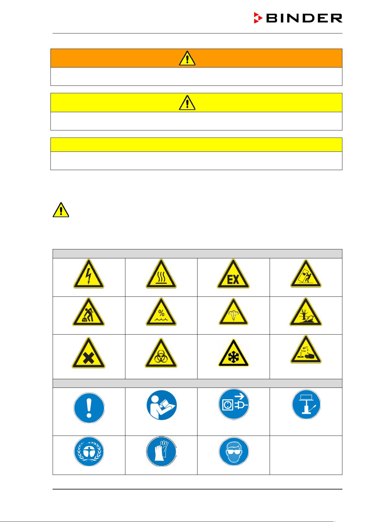
Warning signs
Electrical hazard
Hot surface
Explosive atmosphere
Lifting hazard
High humidity
Pollution hzard
or chemical burns
Mandatory action signs
instructions
plug
Environment protection
Wear protective gloves
WARNING
Indicates a potentially hazardous situation which, if not avoided, could result in death or serious (irreversible) injury
CAUTION
Indicates a potentially hazardous situation which, if not avoided, may result in moderate or minor
(reversible) injury
CAUTION
Indicates a potentially hazardous situation which, if not avoided, may result in damage to the product
and/or its functions or of a property in its proximity.
1.2.2 Safety alert symbol
Use of the safety alert symbol indicates a risk of injury.
Observe all measures that are marked with the safety alert symbol in order to avoid death or
injury.
1.2.3 Pictograms
Harmful substances
Biohazard
Scalding hazard
Danger of frost
Stability hazard
Risk of corrosion and /
Mandatory regulation
MKF+ MKFT (E3.2) 07/2017 page 6/115
Read operating
Disconnect the power
Wear safety goggles
Lift with mechanical
assistance
Page 7
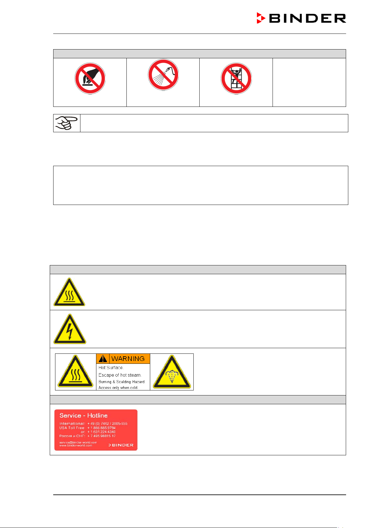
Prohibition signs
water
Pictograms (Warning signs)
Service label
Do NOT touch
Information to be observed in order to ensure optimum function of the product.
Do NOT spray with
Do NOT climb
1.2.4 Word message panel structure
Type / cause of hazard.
Possible consequences.
∅ Instruction how to avoid the hazard: prohibition
Instruction how to avoid the hazard: mandatory action
Observe all other notes and inf ormation not necessarily emphasi zed in the same way, in order to avoid
disruptions that could result in direct or indirect injury or property damage.
1.3 Localization / position of safety labels on the chamber
The following labels are located on the chamber:
Hot surface (on outer chamber door)
Electrical hazard
(chamber with voltage and frequency changer : on the voltage and frequency changer)
Burning and scalding hazard
(on chamber rear)
MKF+ MKFT (E3.2) 07/2017 page 7/115
Page 8
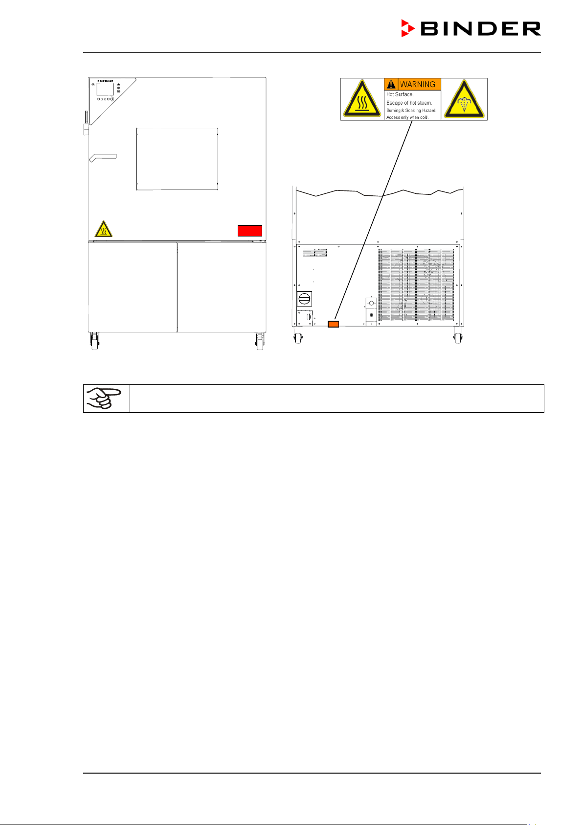
Figure 1: Position of labels on the chamber
Keep safety labels complete and legible.
Replace safety labels that are no longer legible. Contact BINDER service for these replacements.
MKF+ MKFT (E3.2) 07/2017 page 8/115
Page 9
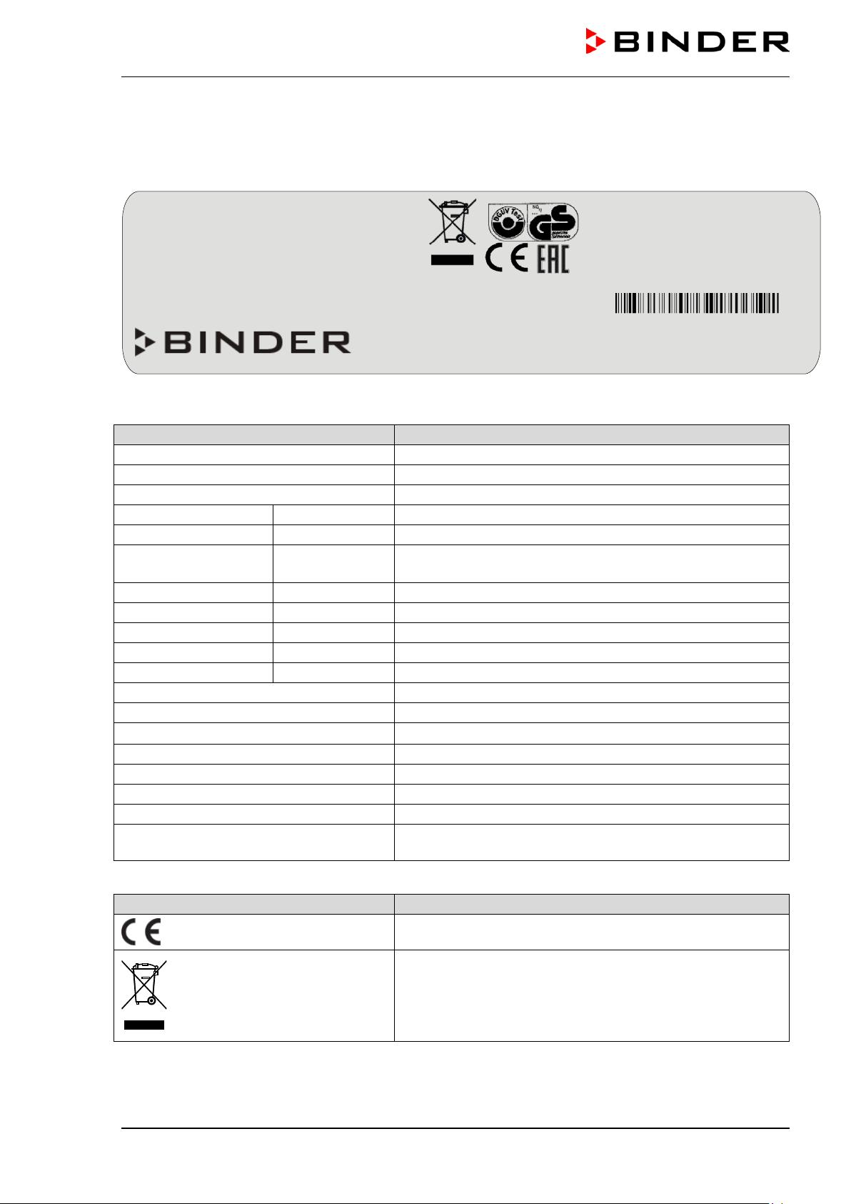
Indications of the type plate (example)
Information
BINDER
Manufacturer: BINDER GmbH
MKFT 240
Model designation
Alternating climate chamber
Device name
Serial No.
000000000000
Serial no. of the chamber
Built
2017
Year of construction
180 °C
356°F
IP protection
20
IP type of protection acc. to standard EN 60529
Temp. safety device
DIN 12880
Temperature safety device acc. to standard DIN 12880
Class
2.0
Class of temperature safety device
Art. No.
9020-0286
Art. no. of the chamber
Project No.
---
Optional: Special application acc. to project no.
6,50 kW
Nominal power
12,0 A
Nominal current
400 V / 50 Hz
Nominal voltage ± 10% at the indicated power frequency
3 N ~
Current type
Max operating pressure 29 bar
Max operating pressure in the refrigerating system
Stage 1: R 404A – 2,20 kg
Cooling 1st stage: Refrigerant type, filling weight
Stage 2: R 23 – 0,40 kg
Cooling 2nd stage: Refrigerant type, filling weight
covered by the Kyoto Protocol
Kyoto Protocol
Symbol on the type plate
Information
Nominal temp.
180 °C
6,50 kW / 12,0 A
Max. operating pre s sure 29 bar
356 °F
400 V / 50 Hz
Stage 1: R 404 A – 2,20 kg
IP protection
20
Stage 2: R 23 - 0,40 kg
Safety device
DIN 12880
3 N ~
Contains fluorinated greenhouse gases
Class
2.0 covered by the Kyoto Protocol
Art. No.
9020-0286
Project No.
Built
2017
Alternating climate chamber
BINDER GmbH
www.binder-world.com
MKFT 240
Serial No. 00000000000000
1.4 Type plate
The type plate stick s to the left side of the chamber, bottom right-hand, above the refrigerating and humidity module.
Im Mittleren Ösch 5
78532 Tuttlingen / Germany
E3.2
Figure 2: Type plate (example of MKFT 240 regular unit)
Made in Germany
Nominal temperature
Contains fluorinated green hous e gas es
Nominal temperature
Contains fluorinated green hous e gas es cover ed b y the
CE conformity marking
Electrical and electronic equipment manufactured / placed
on the market in the EU after 13 August 2005 and be disposed of in separate collection according to Directive
2012/19/EU on waste electrical and electronic equipment
(WEEE).
MKF+ MKFT (E3.2) 07/2017 page 9/115
Page 10
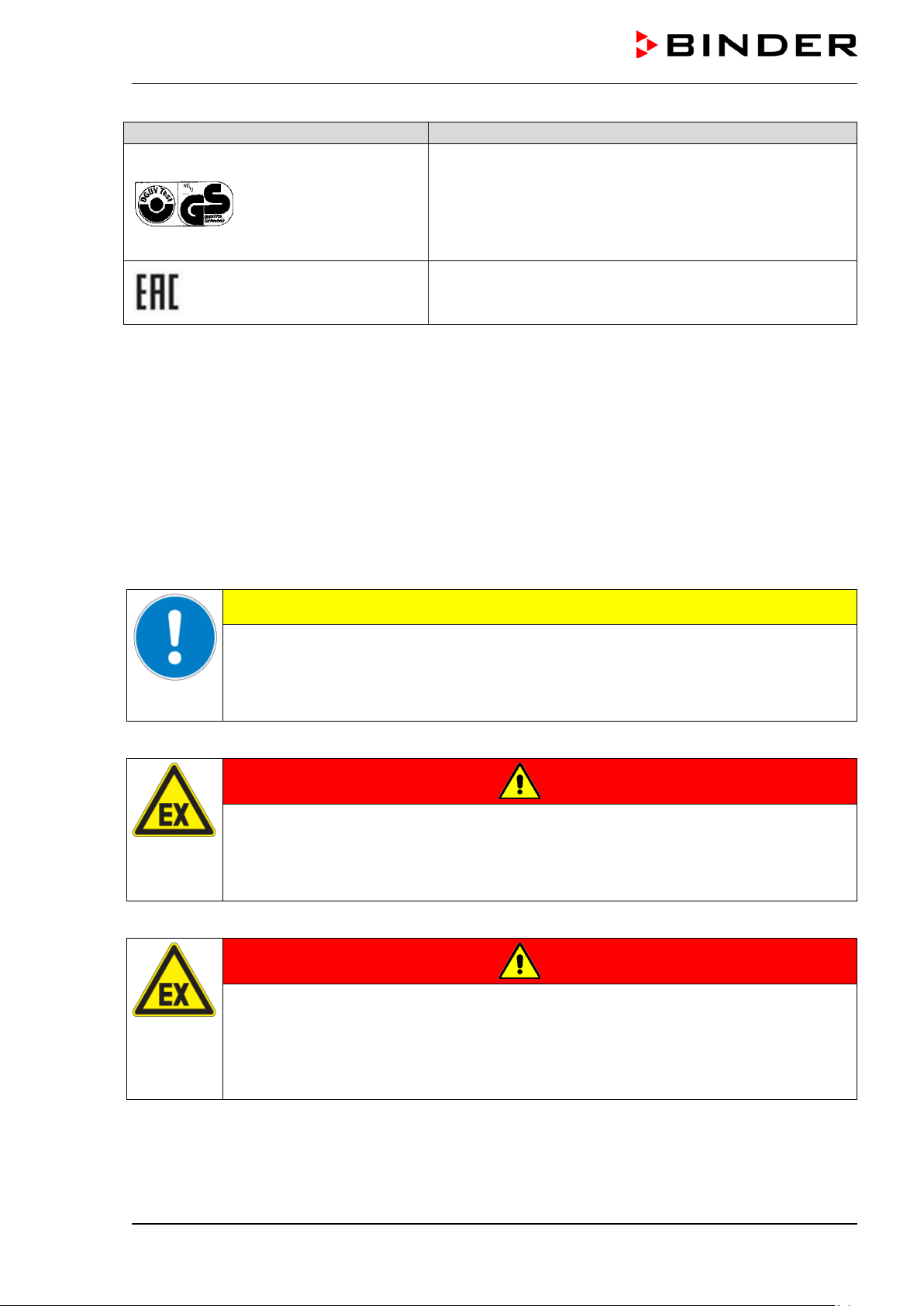
Symbol on the type plate
Information
GS mark of conformity of the “Deutsche Gesetzliche Unfallversicherung e.V. (DGUV), Prüf- und Zertifizierungsstelle
Nahrungsmittel und Verpackung im DGUV Test“ (German
Social Accident Insurance (DGUV), Testing and Certification Body for Foodstuffs and Packaging Industry in DGUV
Test).
The equipment is certified according to Customs Union
Technical Regulation (CU TR) for the Eurasian Economic
Union (Russia, Belarus, Armenia, Kazakhstan Kyrgyzstan).
1.5 General safety instructions on installing and operating the chamber
With regard to operating th e chamber and to the installation location, please observe the DGUV guidelines 213-850 on safe working in laborator ies (formerly BGI/GUV-I 850-0, BGR/GUV-R 120 or ZH 1/119,
issued by the employers’ liability insurance association) (for Germany).
BINDER GmbH is only respons ible for the safety feat ures of the chamber provided sk illed electricians or
qualified personnel authorized by BIND ER perform all m aintenance and repair, and if com ponents relating to chamber safety are replaced in the event of failure with original spare parts.
To operate the chamber, use only original BINDER ac cessories or ac cessories f rom third-par ty suppliers
authorized by BINDER. The user is responsible for any risk caused by using unauthorized accessories.
CAUTION
Danger of overheating.
Damage to the chamber.
∅ Do NOT install the chamber in unventilated recesses.
Ensure sufficient ventilation for dispersal of the heat.
Do not operate the chamber in hazardous locat ions .
DANGER
Explosion hazard.
Danger of death.
∅ Do NOT operate the chamber in potentially explosive areas.
∅ KEEP explosive dust or air-solvent mixtures AWAY from the chamber.
The alternating chamber does not dispose of any measures of explosion pr otec t ion .
DANGER
Explosion hazard.
Danger of death.
∅ Do NOT introduce any substance combustible or explosive at working temperature into
the alternating climate chamber.
∅ NO explosive dust or air-solvent mixture in the inner chamber.
Any so lvent contained in the c harging material m ust not be explosive or inflamm able. I.e., irrespecti ve of
the solvent concentrati on in the steam room, NO explosi ve mixture with air must f orm. The temperature
inside the chamber mus t lie below the flash point or b elow the sublim ation point of the charging m aterial.
Familiarize yourself with the physical and chemical properties of the charging material, as well as the
contained moisture constituent and its behavior with the addition of heat energy and humidity.
MKF+ MKFT (E3.2) 07/2017 page 10/115
Page 11
Familiarize yourself with a ny potential health ris ks caused by the chargi ng material, a possibl y contained
moisture constituent or by reaction products that ma y arise during the con ditioning process. Take adequate measures to exclude such risks prior to putting the chamber into operation.
DANGER
Electrical hazard.
Danger of death.
∅ The chamber must NOT become wet during operation or maintenance.
The chambers were produ ced in accordance with VDE regu lations and were routinel y tested in accordance to VDE 0411-1 (IEC 61010-1).
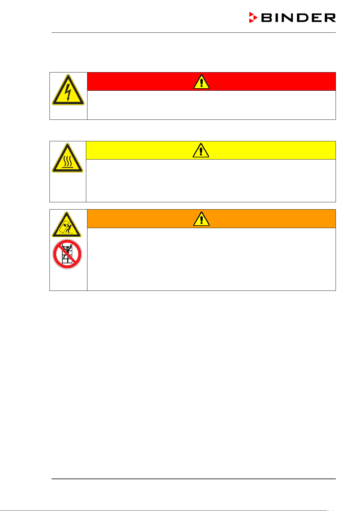
CAUTION
The window, the access ports and the inner chamber will become hot during operation.
Danger of burning.
∅ Do NOT touch the window, the access ports, the inner surfaces or the charging material
during operation.
WARNING
Stability hazard.
Danger of injury.
Damage to the chamber and the charging material.
Housing cover breakaway.
∅ Do NOT climb on the lower housing cover.
∅ Do NOT load the lower housing cover with heavy objects while the chamber door is
open.
MKF+ MKFT (E3.2) 07/2017 page 11/115
Page 12
1.6 Intended use
Alternating climate c hambers series MKF / MKFT are suitable for temper ature drying and heat treatm ent
of solid or pulverized c hargi ng m aterial, as well as bu lk m aterial, usi ng the s uppl y of heat. T he y are su itable for harmless materials . A mixture of any component of the charging m aterial with air must NOT be
explosive. The operat ing tem perature mus t lie below the flas h point or b elow the sublim ation point of the
charging material. Any component of the charging material must NOT be able to release toxic gases.
Other applications are not approved.
The cham bers ar e specially d esign ed for s olving all th e problem s which occ ur du ring m aterial an d age ing
tests.
The chambers are not cl assified as medical devices as defined b y the Medical Dev ice Directive
93/42/EEC.
Due to the special demands of the Medical Device Directive (MDD), these ovens are not qualified for sterilization of medical devices as defined by the directive 93/42/EWG.
Following the instructions in this operating manual and conducting regular maintenance work
(chap. 17) is part of the intended use.
The chambers do not dispose of any measures of explosion protection.
DANGER
Explosion or implosion hazard.
Danger of poisoning.
Danger of death.
∅ Do NOT introduce any subs tance com bustible or ex plosiv e at work ing temper ature into
the chamber, in particular no energy sources such as batteries or lithium-ion batteries
∅ NO explosive dust or air-solvent mixture in the inner chamber.
∅ Do NOT introduce any substance which could lead to release of toxic gases.
The charging material shall not contain any corrosive ingredients that may damage the machine components made of stainless steel, aluminum, and copper. Such ingredients include in
particular acids and halides. Any corrosive damage caused by such ingredients is excluded
from liability by BINDER GmbH.
In case of foreseeable use of the chamber there is no risk for the user through the integration of the
chamber into systems or by special environmental or operating conditions in the sense of EN 610101:2010. For this, the intended use of the chamber and all its connections must be observed.
1.7 Operating instructions
Depending on the applicati on and l ocation of the chamber, the operator of the chamber m ust provide the
relevant information for safe operation of the chamber in a set of operating instructions.
Keep these operating instructions with the chamber at all times in a place where they are
clearly visible. They must be comprehensible and written in the language of the employees.
MKF+ MKFT (E3.2) 07/2017 page 12/115
Page 13

1.8 Measures to prevent accidents
The operator of the chamber must observe the following rule: “Betreiben von Arbeitsmitteln. Betreiben
von Kälteanlagen, W ärmepumpen und Kühleinrichtungen“ (Operation of work equipment. Operation of
refrigeration systems, heat pumps and refrigeration equipment) (GUV-R 500 chap. 2.35) (for Germany).
The manufacturer took the following measures to prevent ign iti on and ex plos io ns :
• Indications on the type plate
See operating manual chap. 1.4.
• Operating manual
An operating manual is available for each chamber.
• Overtemperature monitoring
The chamber is equipped with a temperature display, which can be read from outside.
The chamber is equipped with an additional safety controller (temperature safety device class 2 acc. to
DIN 12880:2007). Visual and audible (buzzer) signals indicate temperature exceeding.
• Safety, measurement, and control equipment
The safety, measuring, and control equipment is easily accessible.
• Electrostatic ch arg e
The interior parts are grounded.
• Non-ionizing radiation
Non-ionizing radiatio n is not intentionall y produced, but release d only for technica l reasons by electr ical equipment (e.g. electric motors, power c ables, solenoids). The m achine has no permanent m agnets. If persons with active im plants (e.g. pac emaker s, defibrillators ) keep a s afe distance (distanc e of
field source to implant) of 30 cm, an influence of these implants can be excluded with high probability.
• Protection against touchable surfaces
Tested according to EN ISO 13732-1:2008.
• Floors
See operating manual chap. 3.4 for correct installation
• Cleaning
See operating manual chap. 17.2.
• Examinations
The chamber has been inspected by the “Deutsche Gesetzliche Unfallversicherung e.V. (DGUV)
(German Social Accident Insurance (DGUV)” (German Social Accident Insurance (DGUV), Testing
and Certification Body for Foodstuffs and Packaging Industry in DGUV Test) and bears the GS mark.
MKF+ MKFT (E3.2) 07/2017 page 13/115
Page 14
Maximum work place
threshold limit value
Tolerated concentration
with permanent load
Substance
Formula
ppm
mg/m3
ppm
mg/m3
Ammonia
NH3
20
14
5500
4000
Acetone
CH3COCH3
500
1200
3300
8000
Benzene
300
1200
150000
Chlorine
Cl2
0.5
1.5
0.7
2
Acetic acid
CH3COOH
10
25
800
2000
Ethyl acetate
CH3COOC2H5
400
1400
4000
15000
Ethanol
C2H5OH
500
960
3500
6000
Ethylene glycol
HOCH2CH2OH
10
26
1200
3000
Formaldehyde
HCHO
0.3
0.37
2400
3000
Isopropanol
(CH3)2CHOH
200
500
4800
12000
Methanol
CH3OH
200
260
3500
6000
Methyl ethyl ketone
C2H5COCH3
200
590
3300
8000
Ozone
O3
0.1
0.2
0.5
1
Hydrochloric acid
HCl 2 3
300
500
Hydrogen sulphide
H2S
10
15
350
500
Nitrogen oxides
NOx 5 9 5 9
Sulphur dioxide
SO2 5 13 5 13
Toluol
C6H5CH3
100
380
1300
5000
Xylene
C6H4(CH3)2
100
440
1300
5000
1.9 Resistance of the humidity sensor against harmful substances
The following list of har mf ul substanc es ref ers onl y to the hum idit y sensor a nd do es not i nclu de an y other
materials incorporated in the chamber or prohibited substances in relation to explosion protection.
Some gases - especially clean gases - do not have an y influe nce on th e hum idity sensor . Others do have
a very small influence, whereas others may influence the sensor to a larger extent.
• The following g ases do not influence the sensor and the humidity measurem ent: Arg on (Ar), carbon
dioxide (CO
• The following gases do not , or to a m inor extent inf luence the sensor and the hu midity measurement:
Butane (C
• The following gases do not , or to a m inor extent inf luence the sensor and the hu midity measur ement,
provided that the indicated loads are not exceeded:
),helium (He), hydrogen (H2), neon (Ne), nitrogen (N2), nitrous oxide (N2O), oxygen (O2)
2
), ethane (C2H6), methane (CH4), natural gas propane (C3H8)
4H10
These values are to be considered only as approximate values. The sensor resistance largely depends on the temperatur e and hum idity conditio ns during t he time of exposure to harm ful substanc es.
Avoid simultaneous condensation. Tolerated error of measurement: ± 2 % r.H. The maximum work
place threshold limit value is the one that can be regarded as harmless for humans.
• Vapors of oil and fat are dangerous for the sens or because they may condensate at t he sensor and
thus prevent its function (insulating la yer). For similar reasons it is not possible to measure smoke
gases.
MKF+ MKFT (E3.2) 07/2017 page 14/115
Page 15

2. Chamber description
The alternat ing clim ate cham ber MKF / MKFT is a special ly developed pr ecision c ooling/ warming cabi net
for the domain of industrial material testing and environment simulation, with an unrivalled c ap acity, which
far exceeds the capabil ities of normal test cabinets, prov iding the ideal facilities for solving all the problems which occur during material as well as ageing and stress tests.
The chambers ar e equipped with a m ultifunctional microproces sor displa y controller with 2-channe l technology for temperature and humidity plus a digital display accurate to on e-tenth of a degree resp. 0.1%
r.H. With its com prehensive program control functions, the d isplay program controller MB1 permits the
high precision perfor mance of temperature and h umidity cycles with rapid he ating up and cooling do wn
phases.
With its micropr ocessor c ontrolled hum idifying and dehum idifying s ystem the chamber is a high-precision
climatic test cham ber . It c o vers th e r e gu lar t es t s pecif i c ations for temperature and c lim ates c orr es pon ding
to DIN und IEC stan dards. Furthermore, it permits simulat ing exac tl y and o ver lon g periods const ant co nditions for other app lications such as sam ple conditioning for m aterial testing of paper, tex tiles, plastics,
building materials, etc.
The patented APT .line™ prehea ting cham ber and a ir conduc tion tech nolog y guarante es excellent spatia l
temperature and hum idity values for the tota l working area. The chamber provides a power ful refrigerating system with rapid coo ling-down spee ds. In addition, the chamber provides almost unlim ited possibilities for adaptation to individual customer requirements based upon extensive programming options.
A resistance hum idifying system hum idifies the air. For this purpose, use deionized (dem ineralized) water. The option BINDER Pur e Aqua Service permits using the chamber with an y degree of water hardness.
The high-quality hous ing insulat ion guarante es both a lo w noise mode of operation an d a c o nsis te ntly low
housing temperature. T he inner chamber, the pre-heating cham ber and the interi or side of the doors are
all made of stainless steel V2A (German m aterial no. 1.4301, US equivalent AISI 304). W hen operating
the chamber at tem per atur es abo ve 150 °C / 302°F, the impac t of the oxygen in the air may cause discoloration of the metallic s urfaces (yellowish-brown or blue) b y natural oxidation processes . These colorations are harmless and will in no way impair the function or qualit y of the chamber. The housing is RA L
7035 powder-coated. All corners and edges are completely coated.
The efficient program controller is equipped with a m ultitude of oper ating f unctions , in additio n to recorder
and alarm functions. Programm ing of tes t cycles is easily accomplished via the modern c olor-display controller MB1 and is also possible directly with a computer via Intranet in connection with the communication
software APT-COM™ 3 DataCo ntrolSystem (option, c hap. 16.1). The chamber comes equipp ed with an
Ethernet serial interf ace for computer comm unication. In addition, th e BINDER communic ation software
APT-COM (option) perm its networking up to 30 chambers and connec ting them to a PC for controlling
and programming, as wel l as recording and repr esenting temper ature and humidity data. F or further options, see chap. 20.6.
The chambers ar e equipped with
brakes.
Temperature ranges:
• MKF without hum idity: -40 °C / 104 °F up to +180 ºC / 356 °F,
four castors . Both front castors can be easi ly locked via the attached
• MKF in climatic operation: + 10 °C / 50 °F up to +95 °C / 203 °F
• MKFT without humidity: -70 °C / -94 °F up to +180 ºC / 356 °F
• MKFT in climatic operation: + 10 °C / 50 °F up to +95 °C / 203 °F
• MKF / MKFT in climatic operation with optional compressed air dryer:
0 °C / 32 °F up to +95 °C / 203°F
Humidity ranges:
• MKF / MKFT: 10% up to 98% r.H.
• MKF / MKFT with optional compressed air dryer: 5 % r.H. up to 98% r.H.
MKF+ MKFT (E3.2) 07/2017 page 15/115
Page 16

(A)
(F)
2.1 Chamber overview
(B)
(C)
(D)
(E)
Figure 3: Alternating climate chamber MKF / MKFT
(A) Instrument panel
(B) Door handle
(C) Window
(D) Door
(E) Refrigeration machine
(F) Access to fill the water can and to the humidity generation module
MKF+ MKFT (E3.2) 07/2017 page 16/115
Page 17
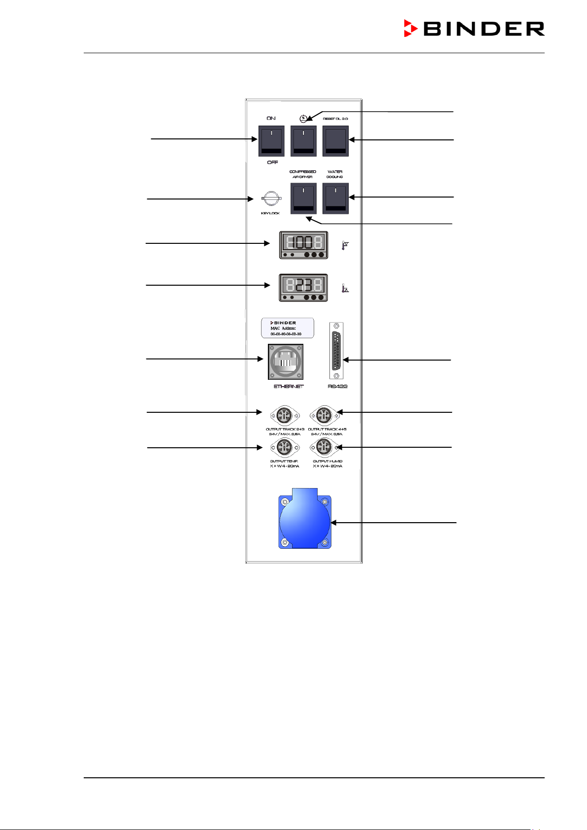
2.2 Lateral control panel
(3)
(6)
(9a)
(9b)
(10a)
(11)
(13)
(4)
(5)
(7)
(8)
(10b)
(12)
(14)
(15)
Figure 4: Lateral control panel MKF / MKFT at the right side of the humidity module with options
(3) Main power switch ON/OFF
(4) Humidity switch ON/OFF
(5) Reset switch for over and under temperature safety device class 2 (option)
(6) Key switch for keyboard locking (option)
(7) Switch for water cooling (only with MKF / MKFT 115 and 240) (option)
(8) Switch for compressed air dryer (option)
(9) Temperature safety device class 2 for over and under temperature (option):
Entry displays for upper (9a) and lower (9b) temperature limit
(10a) Ethernet interface for computer communication
(10b) RS422 interface for computer communication (option)
(11) 2 zero-voltage relay outputs via operation lines 2 and 3
(12) 2 zero-voltage relay outputs via operation lines 4 and 5
(13) Analog output temperature (option)
(14) Analog output humidity (option)
(15) Socket 230 V AC, max. 500 W
MKF+ MKFT (E3.2) 07/2017 page 17/115
Page 18
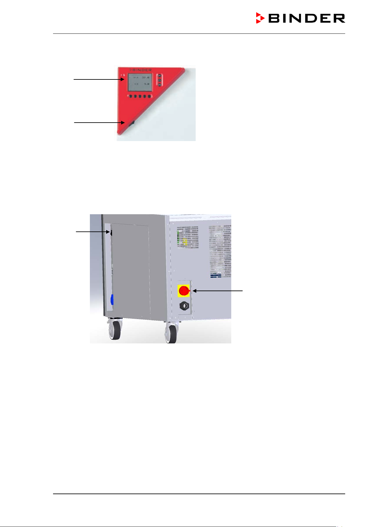
2.3 Instrument panel
(1)
(2)
(1) Microprocessor program controller MB1 with 2-channel technology for temperature and humidity
(2) Switch for interior chamber light
Figure 5: Triangle instrument panel
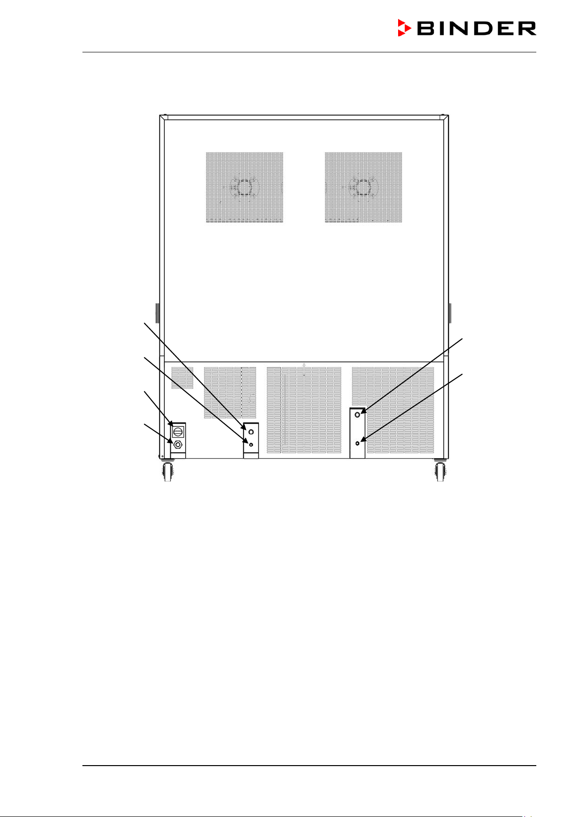
2.4 Rear power switch
(3)
(20)
Figure 6: Rear view of the chamber
(3) Main power switch
(20) Rear power switch
MKF+ MKFT (E3.2) 07/2017 page 18/115
Page 19
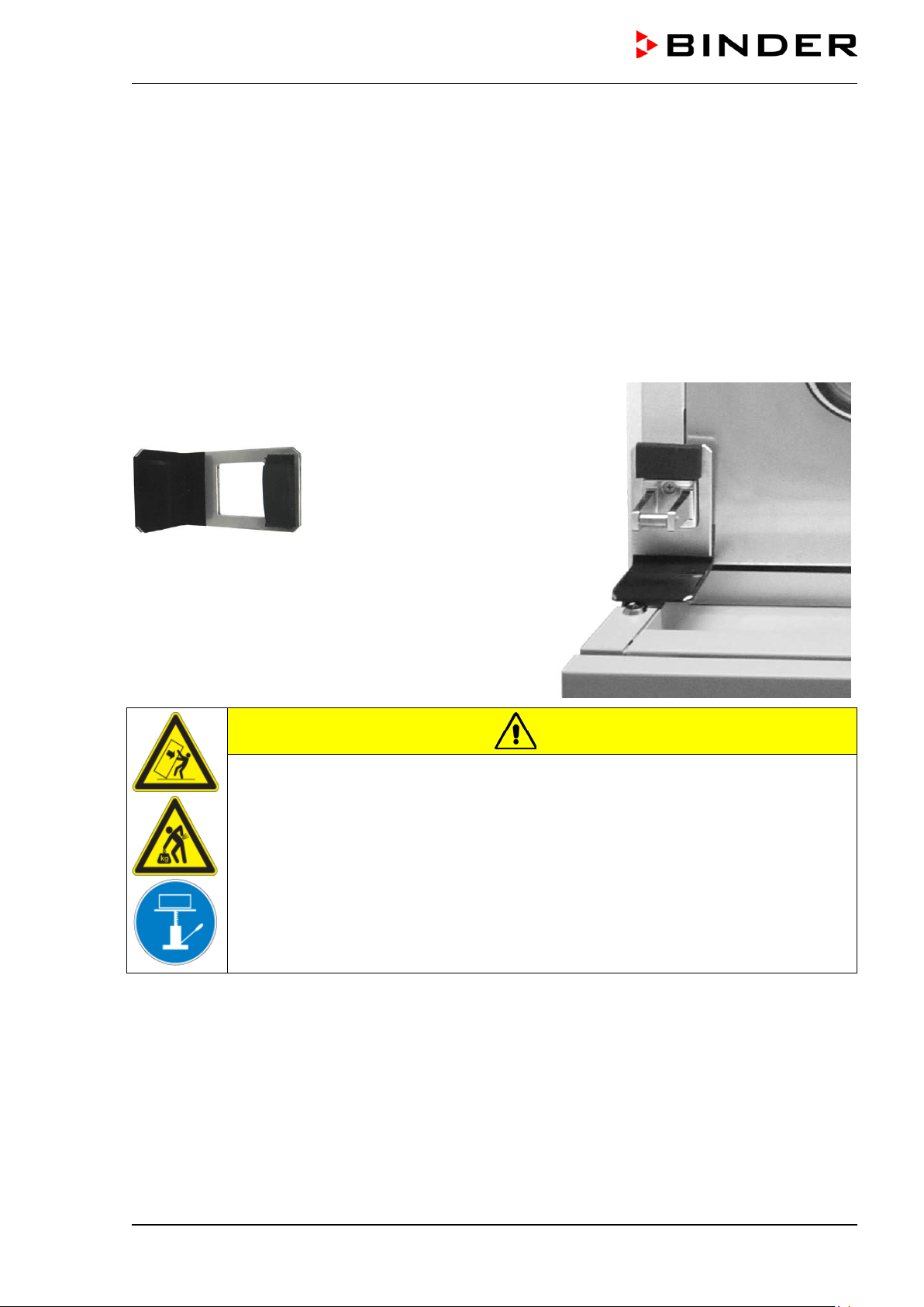
Remove the upholstered transport piece (L-type profile)
3. Completeness of delivery, transportation, storage, and installa-
tion
3.1 Unpacking, and checking equipment and completeness of delivery
After unpacking, p lease check the chamber and its o ptional accessories, if any, base d on the delivery
receipt for completenes s and for transportation damage. I nform the carrier immediately if transportation
damage has occurred.
The final tests of the manufactur er m a y have caused t rac es of the s helves on the i nner s urfaces. This has
no impact on the function and performance of the chamber.
Please remove an y transportation protection de vices and adh esives in/on th e chamber and on th e doors
and take out the operating manuals and accessory equipment.
from the lower door locking and keep it for possible later
transportation.
Figure 7:
Door locking with transport piece (state of delivery)
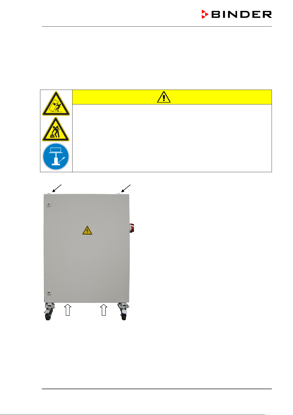
CAUTION
Sliding or tilting of the chamber.
Damage to the chamber.
Risk of injury by lifting heavy loads.
∅ Do NOT lift or transport the chamber using the door handle, the door or the lower
housing.
∅ Do NOT lift the chamber by hand.
Keep the chamber in upright position.
Lift the chamber from the pallet using technical devices (fork lifter). Set the fork lifter
only from the rear in the middle of the chamber. Make sure to place all the lateral supports of the chamber on the forks.
If you need to return the chamber, please use the original packing and observe the guidelines for s afe
lifting and transportation (chap. 3.2).
For disposal of the transport packing, see chap. 18.1.
Note on second-hand units (Ex-Demo-Units)
Second-hand units ar e chambers that have been used for a short time for tests or ex hibitions. They are
thoroughly tested before resale. BINDER ensures that the chamber is technically sound and will work
flawlessly.
Second-hand units are marked with a sticker on the chamber door. Please remove the sticker before
commissioning the chamber.
MKF+ MKFT (E3.2) 07/2017 page 19/115
Page 20
3.2 Guidelines for safe lifting and trans por ta tion
The front castors of the cham ber c an be block ed by b rak es. Please m ove the chambers with cas tors on ly
when empty and on an even surface, otherwise the castors may be damaged. Mount the upholstered
steel L-type profile at t he lo wer do or loc king. After operation p lease obs erve the guidelines for t emporarily
decommissioning the chamber (chap. 18.2).
CAUTION
Sliding or tilting of the chamber.
Damage to the chamber.
Risk of injury by lifting heavy loads.
Do NOT lift or transport the chamber using the door handle, the door or at the lower
housing.
Do NOT lift the chamber by hand.
Transport the chamber only in its original packaging.
Secure the chamber with transport straps for transport.
Keep the chamber in upright position.
Place the chamber using technical devices (fork lifter) on the transport pallet. Set the
fork lifter only from the rear in the middle of the chamber. Make sure to place all the
lateral supports of the chamber on the forks.
Transport the chamber with the original transport pallet. Set the fork lifter ONLY to the
pallet. Without the pallet the chamber is in imminent danger of overturning.
You can order transport packing and pallets for transportation purposes from BINDER service.
Permissible ambient temperature range during transport:
• If the steam humidifying system has NOT been emptied: +3 °C / 37.4 °F to +60 °C / 140 °F.
• After BINDER Service has emptied the steam humidifying system: -10 °C / 14 °F to +60 °C / 140 °F.
With temperatures below +3 °C / 37.4°F, water must be completely removed from the humidifying system.
CAUTION
Transport below +3 °C / 37.4°F with filled steam humidifying system.
Freezing in the steam generator.
Damage to the chamber.
Contact BINDER Service bef or e any transp ortat ion be l o w +3 °C / 37.4°F.
3.3 Storage
Intermediate storage of the chamber is possible in a closed and dr y room. Observe the guidelines for
temporary decommissioning (chap. 18.2).
Permissible ambient temperature range during storage:
• If the steam humidifying system has NOT been emptied: +3 °C / 37.4 °F to +60 °C / 140 °F.
• After BINDER Service has emptied the steam humidifying system: -10 °C / 14 °F to +60 °C / 140 °F.
MKF+ MKFT (E3.2) 07/2017 page 20/115
Page 21
CAUTION
With temperatures below +3 °C / 37.4 °F, water must be complet ely removed from the humidifying system.
Storage below +3 °C / 37.4 °F with filled steam humidifying system.
Freezing in the steam generator.
Damage to the chamber.
Contact BINDER Service before any storage below +3 °C / 37.4 °F.
• Permissible ambient humidity: max. 70 % r.H., non-condensing
CAUTION
Condensation by excess humidity.
Danger of corrosion on the housing after operating at humidity values > 70 % r.H.
for a long period.
Dry the appliance completely before shut-down:
• Set the humidity to 0 % r.H. or turn off humidity switch (4).
• Set the tem perature set point to 150 °C / 302 °F (Manual m ode). Let the chamber
operate for approx. 2-3 hours with closed door. Remove the access port plugs.
• Only then, shut do w n th e chamber at the main p o wer s witc h (3) an d c lose the tap of
the water supply.
After drying the chamber for decommissioning, the humidity value will approximate ambient
humidity.
When after storage in a co ld location you transfer the chamber to its warmer ins tallation site, condensation may form. Before s tart-up, wait at least two hour s until the chamber has att ained ambient temper ature and is completely dry and the oil in the compressors has warmed up.
In case of a prolonged temporal d ecommissioning: Leave the chamber door open or remove the ac cess
port plugs.
3.4 Location of installation and ambient conditions
Set up the chamber on a flat, even and non-flammable surface, free from vibration, and in a wellventilated, dry locatio n and align it using a spir it level. The site of installation m ust be capa ble of s upporting the chamber’s weight (s ee technical data, chap. 20.4). T he chambers are designed f or setting up inside a building (indoor use).
When after storage in a co ld location you transfer the chamber to its warmer ins tallation site, condensation may form. Before s tart-up, wait at least two hour s until the chamber has att ained ambient temper ature and is completely dry and the oil in the compressors has warmed up.
CAUTION
Danger of overheating.
Damage to the chamber.
∅ Do NOT set up chambers in non-ventilated recesses.
Ensure sufficient ventilation for dispersal of the heat.
MKF+ MKFT (E3.2) 07/2017 page 21/115
Page 22
• Permissible ambient temperature range during operation: +18 °C / 64. 4 °F to +32 °C / 89.6 °F. At
elevated ambient temperature values, fluctuations in temperature can occur.
The ambient temperature should not be substantially higher than the indicated ambient temperature of +25 °C / 77°F to which the specified technical data relate. For other ambient conditions, deviations from the indicated data are possible.
• Permissible ambient humidity: 70 % r.H. max., non-condensing.
When operating the cham ber at tem perature s et-po ints belo w am bient tem peratu re, hig h am bient hum idity may lead to condensation on the chamber.
• Installation height: max. 2000 m / 6.6 ft. above sea level.
A water tap (1 bar to 10 bar) is neces sary for the installation of the hum idification system. If no suitable
house water connection is available, you can manually supply water by filling the water can (chap. 4.2).
To avoid any possible water damage, provide a floor drain at the location of the device. Select
a suitable installation site to avoid any consequential damage by splashing water.
When placing several chambers of the same size sid e by side, m ainta in a m inimum distance of 250 m m /
9.84 in betwee n each chamber. Wall distances: r ear 300 mm / 11.81 in, sides 200 mm / 7.87 in. Spac ing
above the chamber of at least 200 mm / 7.87 in must also be maintained.
• With optiona l compressed air dryer: Wall distance r ear approx. 1 m / 3.28 ft so that it is possible to
read the status display of the compressed air dryer on the chamber rear.
• Chambers with v oltage and freque ncy changer: rear w all distance of the a lternating clim ate chamber
approx. 1 m / 3.28 ft to set up the voltage and frequency changer
CAUTION
Danger by stacking.
Damage to the chambers.
∅ Do NOT place the alternating climate chambers on top of each other.
To completely separat e the chamber f rom the power supp ly, you mus t disconnect the power plug . Install
the chamber in a way that the power plug is easily accessible and can be easily pulled in case of danger.
With an increased amount of dust in the ambient air, clean the cond enser fan several times a year. We
recommend check ing the fan grid (behind the lef t maintenance access flap) every week. In case of v is ible
dirt accumulation, disconnect the chamber and clean the fan grid by suction.
Avoid any conducti ve dust in the ambiance accor ding to th e chamber layout com plying with pollution degree 2 (IEC 61010-1).
The chamber must not be installed and operated in potentially explosive areas.
DANGER
Explosion hazard.
Danger of death.
∅ Do NOT operate the chamber in potentially explosive areas.
∅ KEEP explosive dust or air-solvent mixtures AWAY from the vicinity of the chamber.
MKF+ MKFT (E3.2) 07/2017 page 22/115
Page 23
4. Installation and connecti ons
(18)
(17)
(20)
(21)
(22)
(16)
Figure 8: Rear view of the chamber with water connections and optional water cooling
(16) Power cable
(17) Wastewater connection “OUT” with hose olive for hose ½“
(18) Freshwater connection “IN” with screw thread ¾’’ for hose ½“, with union nut
(20) Rear power switch
(21) Connection “OUT ” for cooling water ou tlet with s crew thread ¾ ’’ for hose ½“, with union nut (option
water cooling)
(22) Connection “IN” for cooling water inlet with screw thread ¾’’ for hose ½“, with union nut (option
water cooling)
MKF+ MKFT (E3.2) 07/2017 page 23/115
Page 24
4.1 Wastewater connection for humidifying system
Fasten the wastewater h ose to th e waste water c onnec tion “OU T” (17) ( Figure 8) on the rear of the chamber (olive ∅ 14 mm). Observe the following points:
• You can use a part of the supplied tap water hose as a drainage hose. In case another hose is us ed , it
has to be permanently resistant against at least 95 °C / 203 °F.
• Mount the waste water hose with a m axim um pos itive inclinat ion of 1 m and a m ax im um total length of
3 m.
• Protect both ends of the drainage hose with two of the four supplied hose clamps.
Wastewater is collected in an internal can with a volume of approx. 0.5 liters. It is pumped off
only when required, thus there is no continuous wastewater flow.
Protect the wastewater supply at both sides with the supplied hose clamps.
4.2 Freshwater supply for humidifying system
Connect the wastewater pipe before connecting the chamber to a freshwater pipe or filling the
water can.
You can supply the chamber with freshwater via a wat er pipe or b y manua ll y filling the int ernal water can.
It is not necessary to switch between both poss ibilit ies . When connecting to a wat er pip e, th e wa ter c an is
automatically filled.
Water intake temperature NOT below +5 °C / 41 °F and not exceeding 40 °C / 104 °F.
CAUTION
Calcification of the humidifying system.
Damage to the chamber.
Operate the chamber with deionized (demineralized) water only.
Types of suitable water quality
• Deionized water from a water treatment installation alr ead y existin g at the c ustom er's s ite. Con duct iv ity from 1 µS /cm up to a max im um of 20 µS/c m . (Water, which is in equilibrium with the CO
and has a conductivity below 1 µS/cm (ultrapure water), may cause acid corrosion due to its low pH.)
• Water treated by the optional water treatment system BINDER Pure Aqua Service (disposable system). A reusable measuring equipment to assess the water quality is included (chap. 16.6).
in the air,
2
BINDER GmbH is NOT responsible for the water quality at the user’s site.
Any problems and malfunctions that might arise following use of water of deviating quality is
excluded from liability by BINDER GmbH.
The warranty becomes void in the event of use of water of deviating quality.
MKF+ MKFT (E3.2) 07/2017 page 24/115
Page 25
the rear of
4.2.1 Automatic fresh water supply for humidifying system via water pipe
An enclosure inside the chamber contains the conn ection kit for water suppl y and wastewater. I nstall the
water supply connect ion using either the e nclosed water hos e or another pressur e-resistant one. T o accomplish this, remove the c over of the fres hwater c onnection “ IN” (18) (Figure 8) on the rear of the chamber. Protect both ends of the hose with two of the four supplied hose clamps. Before turning on the
chamber, check the c onnection for leaks. W ater supply is automaticall y effected via the freshwater c onnection “IN” (18).
As the chamber only lets in water when required, there is no continuous water flow.
• Supply pressure 1 to 10 bar when connecting to a water pipe.
• Water type: deionized (demineralized) water
• Water intake temperature NOT below +5 °C / 41 °F and not exceeding 40 °C / 104 °F.
• The water intake shall be provided with a shut-off slide or water-tap.
• For the water sup ply, fix the delivered adapter with hose olive on the thread at
the chamber.
• Protect the water supply at one side with the supplied hose clamp.
4.2.2 Manual fresh water supply for humidifying system via internal freshwater can
If no house water connec tion with s uitab le water is av ailable, you ca n m anua lly s upply wat er b y fi lling th e
freshwater can (total volume: 19 liters / 0.67 cu.ft. up to the maximum level mark), which is located behind
the right door of the humidity generation module.
The cover of the water inl et va lve must be screwed on the fres hwater c on nection “IN” (18). Open the do or
(F) (Figure 3) to access the filler neck of one of the water can. You cannot totally tak e out the water can
because of its fix c onnec t io ns . Fil l t he water ca n o nly up to ¾, up to the m axim um level mark. When filling
it too much with the chamber turn ed on, the alarm message “
controller (chap. 13.1). Manually suck off the wat er, or operate the chamber with high temperature and
humidity values until the ex cess water is consum ed. W hen filling it too muc h with the cham ber turned of f,
water can escape from the chamber. Thus, ensure not to f ill the can by more than the maximum level
mark.
To guarantee humidification during 24 hours even at high humidity set-points with manual
water supply, we recommend filling the freshwater can (option) daily at the end of the day.
WATER LEVEL TOO HIGH” is displayed on the
MKF+ MKFT (E3.2) 07/2017 page 25/115
Page 26

(19)
4.2.3 Water circle: lever for condensate recycling (option)
Figure 9: Lever for condensate recycling (open position)
next to the freshwater can behind the maintenance access door
The lever (19) for c ondensate rec ycling is located behind the m aintenanc e access door next to t he freshwater can.
• Open lever (ver tica l position): the condensate f r om the interi or is c onducted to the freshwater can. Use
only with clean interior!
• Closed lever (horizontal position): the condensate is conducted to the wast e water connection. Use this
position in case of soiling / contamination of the interior.
CAUTION
Soiling of the vapor humidification system.
Damage to the chamber.
Conduct the condensate to the wastewater connection in case of soiling / contamina-
tion of the interior (horizontal lever position).
MKF+ MKFT (E3.2) 07/2017 page 26/115
Page 27

4.3 Connection of cooling water outlet for water cooling (option)
An enclosure inside the chamber contains the connection kit for the cooling water inlet and outlet.
• Fasten the coo ling hose to the connection “O UT” (21) (Figure 8) on the rear of the chamber (screw
thread ¾’’).
• You can use a part of the supplied tap water hose as a drainage hose. In case another hose is us e d , it
has to be permanently resistant against max. 50 °C / 122 °F.
• Protect both ends of the drainage hose with two of the f our supplied hose clamps. Befor e turning on
the chamber, check the connection for leaks.
4.4 Connection of cooling water inlet for water cooling (option)
Connect the cooling wat er outl et before connecting the cooling water inlet.
Type of suitable water quality:
• Water intake temperature: max. 10 °C / 50 °F.
• pH value 4-7
• connection pressure: 4 to 10 bar
BINDER GmbH is NOT responsible for the water quality at the user’s site.
Any problems and malfunctions that might arise following use of water of deviating quality is
excluded from liability by BINDER GmbH.
The warranty becomes void in the event of use of water of deviating quality.
An enclosure inside the chamber contains the connection kit for the cooling water inlet and outlet.
• Fasten the cooling water hos e to t he c o nnec t ion “I N” ( 22) (Figure 8) on the re ar o f the chamber (screw
thread ¾’’).
• Install the water supply connec tion using eit her the en closed water hose or anoth er press ure-resistant
one. To acc om plish this, re move the cover of the freshwater conn ec tio n “ IN” (22) ( Figure 8) on the rear
of the chamber.
• Protect both ends of the hose with t wo of the four suppli ed hose clam ps. Before turnin g on the chamber, check the connection for leaks.
MKF+ MKFT (E3.2) 07/2017 page 27/115
Page 28

4.5 Connection kit for connecting the chamber’s freshwater connection to a
water pipe
A safety kit against f looding c aused by bur st water h oses is enclosed with the chamber. It consists of the
following:
• Hose burst protection device
• Hose nozzle with screwing
• 4 hose clamps
• 6m water hose, divisible for the feed hose and drain
Protection principle of hose burst protection:
Whenever a strong water flow of approx. 18 l / min. occurs, e.g. c aused by a burst water h ose, a valve
automatically cuts off the water supply, which can be heard as a clic king noise. The water supply now
remains shut until it is manually released.
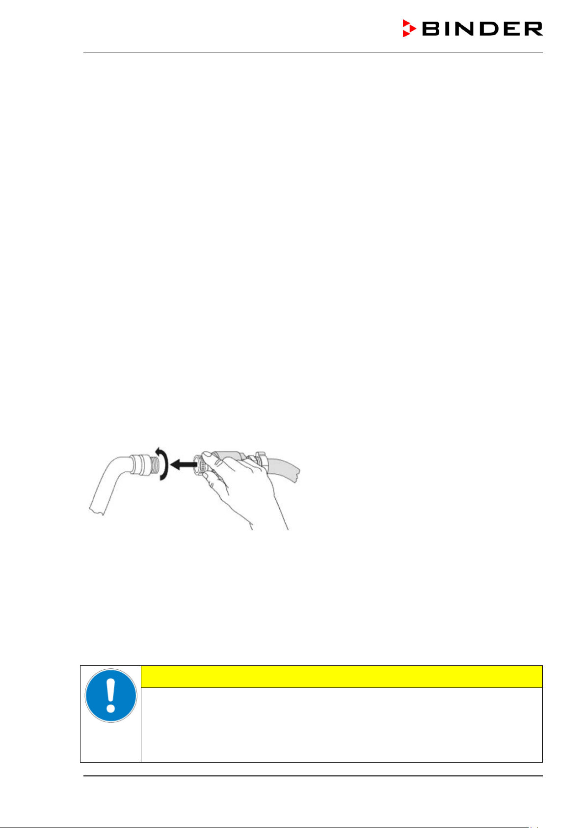
Assembly:
Screw the hose burst protec tion device onto a water tap with a G¾ inch right turning thread connec tion.
The connection is self -sealing. Establish the connecti on between the safety kit and the cham ber with a
part of the supplied hose. Protect both ends of the hose by the supplied hose clamps.
We recommend connectin g t he hose as th e las t s te p in order to a void twisting the hose while scre wing o n
the safety kit.
Open the water tap slowly in order to avoid actuating the hose burst protection device.
Figure 10: Assembly of the connection kit
Release of the reflux protection device:
In case the burst protection device has interru pted the water supp ly, firs t find the r eason and r em ove it as
necessary. Close the wate r tap. Release the valve by a half lef t-turn of the upper knurled part. You can
hear the release of the valve as a c lick ing noise. T ighten the burs t prot ection de vice agai nst the water tap
by a right turn. Open the water tap slowly afterwards.
Maintenance of the assembly of the hose burst protection device:
Calcification can im pair valve function. We recommend an a nnual inspection by a skilled plum ber. The
plumber should rem ove the safety kit to check the valve b y hand for proper function and calc ification or
blockage.
CAUTION
Danger of calcification.
Impairment of valve function.
Have a plumber inspect the valve annually.
Remove calcifications by citric acid or acetic acid solutions.
Continue by testing the function and tightness of the mounted unit.
Check: Quickl y open the water tap while there is n o chamber connected – the valve should cut off the
water flux without any delay.
MKF+ MKFT (E3.2) 07/2017 page 28/115
Page 29
4.6 Safety kit: Hose burst protection device with reflux protection device for
the chamber’s freshwater connection (available via BINDER INDIVIDUAL
customized solutions)
A safety kit with a reflux protec tion device is available for protecti on of the dri nking water system against
flooding caused by burst water hoses.
Protection principles:
Whenever a strong water flow of approx. 18 l / min. occurs, e.g. cause d by a burst water hose, a valve
automatically cuts off the water supply, which can be heard as a clic king noise. The water supply now
remains shut until it is manually released.
A possible endang erin g of the dr inking water system d epen ds o n t he r is k potential of the chargi ng material. Under unfavorable conditions (e.g. decreasing pressure inside the tap water system), drained off
charging material coul d be suck ed out of the cham ber via the steam generator i nto the tap water system
and therefore contaminate the drinking water . The safety kit with a reflux protection device pro vi des s ecurity in case of short-term utilization of s ubstances with low risk potential. W hen using substanc es bearing
a higher risk potent ial, install a pip e disconnector to assure absolute protection. It is the user’s respons ibility to prevent (acc ording to national standards) an y reflux of contaminated water f rom getting into the
drinking water system.
Assembly:
The standard supplied parts – hose burst protection device, hose nozzle with screwing – are not needed.
Screw the pre-mounted as sembly of the hose burst p rotection and ref lux protection de vices onto a water
tap with a G¾ inch right tu rning thread connec tion. The connect ion is self-seal ing. Establish the co nnection between the safety kit and the c hamber with a part of the supplied hose. Protect both ends of the
hose with the supplied hose clamps.
We recommend connectin g the hose as the last step in order to avoid twisting it while s crewing on the
safety kit.
Open the water tap slowly in order to avoid actuating the hose burst pr otec ti on de vice.
Figure 11: Assembly of the safety kit: hose burst
protection and reflux protection devices (option)
Release of the reflux protection device:
In case the hose burst prot ection device interru pts the water supp ly, firs t find th e reason an d rem ove it as
necessary. Close the wate r tap. Release the valve by a half lef t-turn of the upper knurled part. You can
hear the release of the valve as a c lick ing noise. T ighten the burs t prot ection de vice agai nst the water tap
by a right turn. Open the water tap slowly afterwards.
Maintenance of the assembly of hose burst protection and reflux protection devices:
Calcification can impair the function of both valves. We recommend an annual inspection by a skilled
plumber. The plumber should remove the safety kit with the reflux protection device to check the two
valves by hand for proper function and calcification or blockage.
CAUTION
Danger of calcification.
Impairment of valve function.
Have a plumber inspect the two valves annually.
Remove calcifications by citric acid or acetic acid solutions.
Continue by testing the function and tightness of the mounted unit.
MKF+ MKFT (E3.2) 07/2017 page 29/115
Page 30
(a)
(b)
(a)
(b)
Check: Quickl y open the water tap while there is n o chamber connected – the valve should cut off the
water flux without any delay.
4.7 Installation of the voltage and fre quency changer
(chambers with voltage and frequenc y changer )
The voltage and frequency changer is supplied packed separately together with the chamber.
CAUTION
Sliding or tilting of the voltage an d fre q u ency changer.
Damage to the voltage and frequency changer.
Risk of injury by lifting heavy loads.
∅ Do NOT lift the voltage and frequency changer by hand.
Lift the voltage and frequency changer from the pallet using technical devices (for k
lifter). Set the fork lifter only from the rear in the middle of the chamber.
Alternatively, the voltage and frequency changer can also be lifted at the eyelets on
the top by means of a lift truck
(a) Eyelets for lifting with a lift truck
(b) Positions for a forklift
Figure 12: Positioning of aids for lifting the voltage
and frequency changer
For the installation of the voltage and frequenc y changer behind the chamber, pr ovide a rear wall distance of the chamber of approx. 1 m / 3.3 ft.
If possible, fix the volta ge a nd f requenc y changer at the chamber . For this purpose, an Allen k e y size 4 is
required. Connect t he slots at the e nd of the chassis with two M6 scr ews to the threads provided below
on the rear panel of the chamber (see Figure 13).
MKF+ MKFT (E3.2) 07/2017 page 30/115
Page 31

MKF 115
MKF 240
16 Amp
3 x internal
MKF 720
MKFT 720
25 Amp
CAUTION
Danger of overheating.
Damage to the voltage and frequency changer.
∅ Do NOT install the voltage and frequency changer in unventilated recesses.
Ensure sufficient ventilation for dispersal of the heat.
The voltage and frequenc y changer is equipped with four castors. The r ear castors can be easily lock ed
via the attached brakes
4.8 Electrical connection
4.8.1 Information on connecting the alternating climate chamber
The chambers are suppli ed r ead y for c onnection. They come with a fixed p o wer c onnec t ion ca bl e of 2700
mm / 8.9 ft in length and are equipped with3 internal overload releases against excess-current.
Model Power plug
MKFT 115
MKFT 240 CEE plug 5-poles, 16 Amp 400 V at 50 Hz 3 N~
• The domes tic socket must also prov ide a protective conduct or. Make sure that the connection of the
protective conductor of the domes tic installatio ns to th e cham ber ’s protective co nductor meets the latest technology. The protective conductors of the socket and plug must be compatible!
• Prior to con nect ion and s tar t-up, chec k the po wer su ppl y voltag e. Com par e the v alues to the s pecif ied
data located on the chamber’s type plate (left chamber side, bottom right-hand, chap. 1.4)
• When connecting, please observe the regulations specified by the local electricity supply company and
as well as the VDE directives (for Germany). We recommend the use of a residual current circuit
breaker.
• Pollution degree (acc. to IEC 61010-1): 2
• Over-voltage category (acc. to IEC 61010-1): II
CEE plug 5-poles, 16 Amp
CEE plug 5-poles, 32 Amp
Nominal voltage ± 10% at the
indicated power frequency
400 V at 50 Hz
400 V at 50 Hz
Current
type
3 N~
3 N~
Chamber
fuse
16 Amp
3 x internal
3 x internal
CAUTION
Danger of incorrect power supply voltage.
Damage to the equipment.
Check the power supply voltage before connection and start-up.
Compare the power supply voltage with the data indicated on the type plate.
See also electrical data (chap. 20.4).
To completely separate the chamber from the power supply, you must disconnect the power
plug. Install the chamber in a way that the power plug is easily accessible and can be easily
pulled in case of danger.
MKF+ MKFT (E3.2) 07/2017 page 31/115
Page 32

chamber
(H)
(I)
(G)
4.8.2 Connecting the voltage and frequency changer (for chambers equipped with a
voltage and frequency changer)
The voltage and frequenc y changer is supplied with a fixed power connec tion cable without a p lug. It is
protected against exc ess-current with 3 internal overload releases. The connection is m ade by the customer.
The socket must provide a protective conductor.
Electrical connection data:
• Input side: 480 V, 60 Hz, 4-wire
• Output side (to the chamber): 400 V, 50 Hz, 5-wire
To establish the elec trical connection of the alternating climate cham ber with the volta ge and frequency
changer, proceed in the following order:
1. Connect the chamber to the connection socket (G) of the voltage and frequency changer
2. Establish the power connection of the voltage and frequency changer using the power cable (I)
3. Turn on the voltage and frequency changer at the power switch (H) (position “ON”)
4. Turn on the chamber with the main power switch (3) in the lateral control panel
Left side of the voltage and frequency changer
with connection socket (G) for the alternating climate
Figure 13: Voltage and frequency changer, mounted
MKF+ MKFT (E3.2) 07/2017 page 32/115
Right side of the voltage and frequency changer
with power switch (H) and power cable (I)
Page 33

Pilot lamp: Ready for operation
Figure 14: Power switch (H) of the voltage and frequency changer in position “ON”
In position “OFF” the switch can be locked, e.g. with a padlock.
5. Start up
After connecting the supply lines (chap. 4), you can start up the chamber.
• Turn on the rear power switch (20) at least one hour before operating the chamber.
• Turn on the chamber by the main power switch (3) in the lateral control panel.
• Open the water-tap for supply. Alternatively, fill the freshwater can (chap. 4).
• Turn on the humidifying and dehumidifying system with switch (4) (humidity switch ON/OFF).
After the first turn ing on of the hum idity or after an interruption of the po wer supply the re lative humidit y
will increase after a de lay of approx. 20 m inutes. During this period, the r elative humidity can dr op considerably.
The refrigerating and dehu m idification f unctions are a vaila ble onl y one hour af ter turning o n the rear po wer switch (20). This is in dicated by the notific ation “1H PREHEAT PHASE” i n the control ler displa y (chap.
13.1). After 1 minute the m essage “WATER TANK EMPTY” appears on the c ontroller display. You can
reset this message only after the 1-hour prehe ati ng ph ase.
Warming chambers may release odors in t he first few da ys after comm issioning. T his is not a quality de-
fect. To reduce odors quickl y we recommend heating up the chamber to its nom inal temperature for one
day and in a well-ventilated location.
5.1 Function overview of display program controlle r MB1
EXIT button (to exit a menu point)
MKF+ MKFT (E3.2) 07/2017 page 33/115
AUTOMATIC button (to start a previously entered program)
ENTER button (to confirm a selection)
Navigation buttons (functions are assigned by the menu)
Switch for interior chamber light (2)
Figure 15: Temperature and humidity program controller MB1
Page 34

W
X
08:43:55 15.12.13
CONFIG
VIEW->
PGM
TEMP
40.0
36.8
°C
HUMID
65.0
58.6
%rH
HAND
The 2-channel program controller MB1 controls the following values inside the chamber:
• Channel 1: Temperature in °C. Range without humidity: -40 °C / -40°F up to 180 °C / 356°F,
in climatic operation: +10 °C / 50°F up to +95 °C / 203°F.
• Channel 2: Relative humidity in % r.H. Range 10 % r.H. to 98 % r.H.
You can enter the desired set point values in Ma nual Mode or Pro gram Mode (c hap. 5.2) on the display
controller. For the control range of temperature and relative humidity, see chap. 14.
Set point values Actual values
Figure 16: Normal display of the MB1 program controller in Manual mode
5.2 Operating modes
The 2-channel program controller MB1 operates in 3 modes:
Idle Mode
The controller is not functional, i.e., there is no heating or refrigeration and
no humidification. The fan is off.
Manual Mode
(Fixed value operation)
The controller operates as a fixed-point control, i.e., set-points for temperature and humidity can be defined, which are then maintained (chap. 8).
(HAND)
Program Mode (AUTO)
An entered temperature and humidity program is run (chap. 9).
The 2-channel program controller MB1 permits programming temperature and humidity cycles.
The controller off ers 25 program memory positio ns with 100 pr ogram s ections eac h. The total num ber of
program sections of all programs is limited to 500.
Programming can be done directly through the keypad of the contro ller or graphically through the sof t-
ware APT-COM™ 3 DataControlSystem (option, chap. 16.1) specially developed by BINDER.
5.3 Behavior after power failure
After power returns, t he chamber continues to functio n in the or iginal op erating m ode it was in previous ly
before an actual power failure had occurred. In Manual Mode (HAND), t he controller regulates temperature and humidity to the last entered set-po ints, while in Progr am Mode (AUTO) it regulates temper ature
and humidity to their set -points that were re ache d dur ing t he progr am operation . T he po wer failur e is noted in the event list (chap. 6.2) however, no error mes sage is displa yed indicating that a power f ailure has
taken place.
5.4 Behavior when opening the door
When you open the door, temperature control (heating and refrigeration) immediately stops (the compressor continues run ning f or 5 m inutes without c ooli ng). Humidification and dehu m idification are of f. The
fan is off.
MKF+ MKFT (E3.2) 07/2017 page 34/115
Page 35

5.5 Turning on the chamber
Turn on the rear power switch (20) at least one hour before operating the chamber.
Set the main power switch (3) in position I. The pilot lamp shows the chamber is ready for operation.
Observe a delay time of approx. 30s between turning Off and again On the main power switch
(3). Otherwise an initialization problem might occur (display showing e.g. “–1999”).
The refrigerating and dehu m idification f unctions are a vaila ble onl y one hour af ter turning o n the rear po wer switch (preheating phase). This is indicated by the notification “1H PREHEAT PHASE” on the controller
display. After 1 minute the message “W ATER TANK EM PTY” appears on th e controller display. You c an
reset this message only after the 1-hour preheating phase.
Note that the cham ber is i n stand-b y mode when t he m ain power s witch is in pos ition I and t he contr oller
display is dark. Turn on the chamber by pressing any button. W hen turned on, the chamber f unctions in
the operating mode enter e d bef or e turning off. In Manual Mode (H AN D) , the c o nt rol ler re gu lates t emperature and humidit y to the last entered set-poi nts, and in Program Mode (AUTO) it regulates tem perature
and humidity to their set-points reached during previous program operation.
Structure of toggling between Idle Mode / Manual Mode / Program Mode:
Menu Program start
Program Mode (AUTO)
or
For control reasons the refrigeration machine starts with a delay time. The refrigeration machine also turns off with a 5 minutes delay. This explains why the compressor may remain
operating also during positive temperature jumps.
Idle Mode
HAND
Manual Mode (HAND)
EXIT
EXIT
MKF+ MKFT (E3.2) 07/2017 page 35/115
Page 36

User Level
Date and time
Summer time
Language
Temperature unit
Buzzer
Safety controller
User-code No.
English
°C 1 Active
Sollwert Art
Offset
Language
English
User-settings
Instrument data
Contrast
Displ. Power down
Contin. operat i o n
User Level
Safety control. Act + 36.8°C
Safety control. Set. 38.5
°C
29
User-Settings
08:43:55 15.12.13
Configuration 2
Configuration 1
Parameters
Choose variation
08:43:55 15.12.13
Configuration 2
Parameters
Choose variation
Configuration 1
User-Settings
CONFIG
4 X
6. Controller MB1 settings
6.1 Selection of the menu language
The display program controller MB1 c ontrols the tem perature and hum idity inside the ch amber. T he controller communicates by a menu guide using real words in German, English and French.
The selection of the desired menu language is located in the sub-menu “User-Level” of the “UserSettings” menu. Select menu point “Language“.
User level code no. 1 (factory setting)
The row of buttons below the dis p lay is context-sensitive. The insc ripti on ab o ve th e butto ns on the d isplay
defines the button’s function.
Do NOT change the temperature unit from °C to °F.
MKF+ MKFT (E3.2) 07/2017 page 36/115
Page 37

(Idle Mode or Manual Mode or
VIEW ->
point values (X).
CONTACT PAGE
NORMAL DISPLAY Idle Mode
W
X
08:43:55 15.12.
13
CONFIG
VIEW->
PGM
TEMP
0.0
26.8
°C
HUMID
0.0
58.6
%rH
HAND
W
X
08:43:55 15.12.13
CONFIG
VIEW->
PGM
X - TEMP
26.8
°C
X - HUMID
58.6
%rH
HAND
No heating or refrigeratio n, no hum idificati on or dehum idificat ion. T he ac tual value s (X) approx im ate ambi-
NORMAL DISPLAY Manual Mode
W
X
08:43:55 15.12.13
CONFIG
VIEW->
PGM
TEMP
40.0
36.8
°C
HUMID
65.0
58.6
%rH
HAND
according to the previous entered set-points (W).
NORMAL DISPLAY Program Mode
W X
08:43:55 15.12.13
PROGRAM 01/SEC1 00:09:59
CONFIG
HAND VIEW->
PGM
TEMP
40.0
36.8
°C
HUMID
65.0
58.6
%rH
AUTO
A temperature and humidity program entered before
via a program table is run.
EVENT LIST
CHART RECORDER FUNCTION
corresponds to a supervision period of 2.5 days.
11:32:14 15.12.13
10:45:00
+23.9 °C
H
+22.6 % rH
11:05:00
08:43:55 15.12.13
08:43:55 15.12.13
Service Hotline
International: +49 7462 205 555
USA Toll Free: +1 866 885 9794
or +1 631 224 4340
: +7 495 988 1517
РоссияиСНГ
service@binder-world.com
www.binder-world.com
CONFIG
VIEW-> VIEW->
Best conditions for your success
6.2 Function overview program c ontrol ler MB1
The main operation level contains the following different displays:
• Normal display
Program Mode)
• Event List
• Chart recorder function
• Contact page
Toggle between the displays by pressing button
.
The NORMAL D I S P LAY enables comparis on of the
current temperature and humidity (W) to the set-
BINDER Service contact display.
or
ent temperature and humidity. The fan is off.
Temperature and hum idity values are maintained
Overview over the last 16 events or error occurrences of the unit.
Graphical display of the current temperature and humidity values and review of the previous measurements on a historical displa y. A memory interval of 5s
MKF+ MKFT (E3.2) 07/2017 page 37/115
Page 38

User-settings
Instrument data
Contrast
Displ. Power down
Contin. operation
User Level
Safety control. Act + 100.8 °C
Safety control. Set. + 110.0 °C
29
6.3 Menu settings in the “User-settings” menu
Instrument data
• Instrument Name
Enter an individual name of the chamber.
• Address
Enter a controller address (1 to 30) for operation with the communication software APT-COM™.
All other entries are relevant only for service purposes.
Contrast:
No function.
Displ. power down
• Switch off event
Do not change the entry “Wait. Period”.
• Waiting period
You can enter a delay time after which th e display, following manual acti vation, will automaticall y be
turned off again, on c ondition that t he moment is outs ide the operat ion time defined in menu ”Contin.
operation”.
Contin. operation
Enter an operation tim e to determ ine the per iod of displa y activ it y. Outside t he def ined peri od, the display
is automatically turned of f. Pressing down any key will reac tivate the display. After the time s et in menu
“Displ. power down“, the dis play will turn off again as far as the actua l time is not within the operation tim e
fixed in menu “Cont. operation“.
User Level
Toggle here to the displa y menu “User Level” (c hap. 6.4) by enter ing a passwor d. Factory default s etting
for this password is +00001. You can change the password (“user code”) in the “User Level” menu.
Safety control.Set
The setting of the toleranc e lim it of the saf ety controller (c hap. 12.2) is disp layed. You c annot c hang e it in
this view.
Safety control.Act
The measuring result of the safety controller is displayed. The safety controller compares the value
measured by a second independent temperature sensor to the entered tolerance limit.
MKF+ MKFT (E3.2) 07/2017 page 38/115
Page 39

User Level
Date and time
Summer time
Language
Temperature unit
Buzzer
Safety controller
User-code No.
English
°C
1
Active
6.4 Menu settings in the “User Level” menu
Date and time
Enter the actual date and ti me to pr ovide the proper m easurem ent records . Data is displa yed in the char t
recorder function (chap. 7) of the controller and will remain stored in case of a power failure.
Summer time
Time is set one hour in advance during the summer time period.
Setting the summer time switch:
• Off: No change to summer time occurs
• User timed: Beginning and end of summer time can be set individually
• Automatic: The summer time arrangement for central Europe is enabled (summer time from last
Sunday of March until last Sunday of October)
Language
Select the menu language as German, English, or French (chap. 6.1).
Temperature unit
Do NOT change the temperature unit from °C to °F.
Buzzer
Audible alarm buzzer
• Inactive: No audible alarm will sound if an alarm event happens (chap. 13).
• Active: An audible alarm will sound in case of an alarm event (chap. 13).
Safety controller
Enter a safety controll er tolerance limit to prevent tem perature from exceeding this setting. For settin g,
see chap. 12.2.
User-Code No.
Change the password (“us er code”) needed to acces s the menu “User settings”. Fac tory default setting
+00001.
Make a note of any change in the user password. There is no access to this menu without the
correct password.
MKF+ MKFT (E3.2) 07/2017 page 39/115
Page 40

Normal display of the chart recorder function:
Top left: The actual date and time are displayed.
H
Activation of the optio nal over- or under temperatur e safety device (chap. 12.3) is dis played on the right
History display with cursor:
Select button
H
= History. A pink line appears on
History - zoom function:
: Zoom and zoom
11:32:37 15.12.13
+22.6
% rH
11:32:20 15.12.13
10:45:00
+23.9 °C
+22.6
% rH
11:05:00
11:32:14 15.12.13
10:45:00
+23.9 °C
CONFIG
VIEW->
H
+22.6 % rH
11:05:00
7. Graphic representation of the historical measurement (chart
recorder function)
The representation of data im itates a char t r ecorder a nd al lows rec al ling an y set o f m eas ured data of an y
point of time taken from the recorded period.
Below: The current values of temperature [ °C] and humidity [% r.H.] are numerically and graphically displayed.
Scaling:
MKF: Temperature: -50 °C / -58°F to +200 °C / 392°F
MKFT: Temperature: -100 °C / -148°F to +200 °C / 392°F.
Humidity: 0% r.H. to 100% r.H.
Button
permits toggling between different repre-
sentations.
Depending on the s elected kind of representatio n, button
might not have been visible until this procedure.
side of the display as an enlarged blue line.
The active bedew protection is displayed on the right side of the display as an enlarged green line.
the display marking as a c ursor the selected m om ent. You
can now recall the recorded data of any defined moment.
Top left: Date and tim e of the se lected cursor position are
displayed.
Below: The correspon ding temperature and humidity values of this instance are numerically and graphically displayed.
Scroll the cursor position using the arrow buttons.
Single arrow buttons: fine-tuning.
Double arrow buttons: page-up and page-down.
Switch to the zoom display by pressing butt on
:
Magnifier buttons
back (i.e., shorten or extend the displayed period).
Toggle back to the f ormer representation disp lay using
.
this button
MKF+ MKFT (E3.2) 07/2017 page 40/115
Page 41

Now you can access any moment that you would like to
STA R T
History display at the selected point of time:
Storage rate
Storage duration
(hours)
(days)
5 sec
60
2.5
10 sec
120
5
1 min
720
30
5 min
3600
150
10 min
7200
300
20:30:00 30.11.13
20:00:00
+22.7 °C
+28.4 % rH
21:00:00
19:00:00
Cursor position
Date
Time
Grenzwert
Offset
Date
10.01.02
Offset
Date
30.11.13
11:34:39 15.12.13
STAR
T
Cursor
Date 15.12.13
Time 11:34:27
11:34:27 15.12.13
You can also directly enter any cursor position as a numerical input.
History representation: Toggling to any defined moment:
Press button . The window “Cur sor position” opens
to enter date and time.
Select date or tim e with the arro w butt ons and conf irm with
ENTER.
recall. Enter date and tim e with the ar row butt ons and confirm with ENTER.
Press button
.
Top left: Date and tim e of the selected cursor pos ition are
displayed.
Below: The corresponding temperature and humidity values of this moment are numerically and graphically displayed.
The available presentatio n depends on the pre-s elected storage rate. This means the higher the stora ge
rate, the more precisely but shorter the data representation will be, see table below:
Setting the storage rate clears the measured-value memory.
Danger of information loss.
Change the storage rate ONLY if the previously registered data is no longer needed.
The cursor line marks the corresponding moment.
CAUTION
MKF+ MKFT (E3.2) 07/2017 page 41/115
Page 42

Configuration 1
Diagram view
Feed view
Event tracks
Datalogging
Interface
Analog view
Time/div
Sollwert Art
Storage rate
EXIT
Datalogging
Normal operation
Event operation
Timed operation
Normal operation
Store status
Store value
s
Storage rate
Actual val.
60s
On
CONFIG
User-Settings
Configuration 2
Configuration 1
Parameters
Choose variation
Parameters
Choose variation
2 X 3 X
11:44:17 20.12.13
11:44:17 20.12.13
2 X
User-Settings
Configuration 2
Configuration 1
Grenzwert
Offset
User-Code ?
+00001
1 X
7.1 Setting the storage rate
Enter the storage rate with the arrow keys and
confirm by pressing “ENTER”.
To leave this menu pr es s the “ EX IT ” button s ev eral
times.
MKF+ MKFT (E3.2) 07/2017 page 42/115
Page 43

Arrow buttons to select the operation
(Operation line 1 = bedew protection)
Arrow buttons to
08:43:55 15.12.13
HAND
08:43:55 15.12.13
Operating contacts
DRY
Contact 2
Contact 3
Contact 4
Contact 5
Contact
Contact 7
Contact 8
On
Off
Aus
Aus
Aus
Aus
Aus
Off
HAND
DRY
Off
On
Hand-Mode
TEMP
Oper
+40.0 °C
+80.0 %
TEMP
+0060.0
°C
HUMID
+65.0 %r.H.
EXIT
08:43:55 15.03.13
HAND
HAND
Hand-Mode
TEMP
Steuerkontakte
+29.3 °C
+80.0 %
Hand-Mode
TEMP
Operating contacts
+40.0 °C
PGM
CONFIG
W
VIEW->
EXIT
HUMID
+65.0 %r.H.
W
X
08:43:55 15.12.13
CONFIG
VIEW->
PGM
TEMP
0.0
26.8
°C
HUMID
0.0
58.6
%rH
HAND
8. Manual Mode
In Manual Mode (HAND) you can enter a temperatur e set-point, a humidit y set-point, and the switch ingstate of up to 8 operation lines. O peration line 1 can be used to c ontrol the bedew protec tion (chap. 10).
Operation lines 2 to 5 serve to switch an y device connec ted to the zero-voltage relay outp uts (DIN soc kets (11) and (12), chap . 11). Operation line 8 re leas es the com pres sed air dr yer (opti on, c hap. 16.7). The
other operation lines are non-functional. All set tings remain valid in Ma nual Mode (HAND) until the next
manual change, if th e chamber had b een turned off or in case of toggli ng to Idl e Mode or Program Mode
(AUTO).
8.1 Set-point entry
Idle Mode
No heating or refrigerating function,
no humidification.
The fan is off.
Toggling to Manual Mode
Change of page
Toggling between temperature set-point, humidity set-point, and operation lines.
6
lines
Unlock the keyboard locking (option, chap. 16.5) via the key switch to enter the set-point.
MKF+ MKFT (E3.2) 07/2017 page 43/115
Button to move the decimal point
enter the value
Page 44

Ranges:
Temperature
MKF
Temperature
MKFT
Humidity
Setting range (range -50 °C up to -40 °C
not provided for operation)
Control range without humidity
Control range in climatic operation
Control range in climatic operation, with
optional compressed air dryer
Setting range (range -80 °C up to -70 °C
not provided for operation)
Control range without humidity
Control range in climatic operation
Control range in climatic operation, with
optional compressed air dryer
-50 °C / -58°F up to 180 °C / 356°F
- 40ºC / -40°F to + 180ºC / 356°F
+ 10 °C / 50°F up to +95 °C / 203°F
0 °C / 32 °F up to +95 °C / 203°F
-80 °C / -112 °F up to 180 °C / 356°F
-70 ºC / -94 °F up to 180 °C / 356°F
+ 10 °C / 50°F up to +95 °C / 203°F
0 °C / 32 °F up to +95 °C / 203°F
Setting range 0 % r.H. up to 100 % r.H.
Control range 10 % r.H. up to 98 % r.H.
Control range with optional compressed
air dryer
5 % r.H. up to 98% r.H.
For possible combinations of temperature and humidity values without condensation,
see temperature / humidity diagram in chap. 14. Outside the indicated control range for
temperature and humidity the humidity system is automatically turned off. The entry of
the humidity set-point 0 % r.H. permits completely turning off humidity in defined program section and thus attaining faster temperature changes.
For the control range of tem peratur e and relativ e humidit y, see the tem per ature / hum idity diagr am (chap.
14).
With set-point type “Limit”, adapt the safety controller (chap. 12.2) always when you changed
the temperature set-point. Set the safety controller set-point by approx. 10 °C above the controller temperature set-point.
We recommend keyboard locking (option, chap. 16.5.) during operation.
In case of the optional temperature safety device (chap. 12.3), check and, if necessary, adjust
the temperature limits entered there.
In Manual Mode, no progr am c an be started. Set -point s can be ent ered for tem perature an d for hum idity.
The actual values equilibrate to these set-points.
When pushing the EX IT button in Manua l Mode, the contr oller changes to Idle Mode. The set -points entered in Manual Mode remain saved.
When incidentally pressing the EX IT button duri ng Man ual Mod e operat io n, the co ntr oller will
change to Idle Mode and thus will not adjust any longer to the program set-points.
We recommend keyboard locking (option, chap. 16.5.) during operation.
For a negative set-point entry, enter the numerical value first and then the minus sign (-).
When operating without humidity (humidity switch (4) OFF), set the humidity set-point in Manual Mode to 0 % r.H. in order to avoid alarms (in case of the humidity deviating by more than +/5% from the set-point).
MKF+ MKFT (E3.2) 07/2017 page 44/115
Page 45

W
X
08:43:55 15.12.13
PROGRAM 01/SEC1 00:09:59
CONFIG
HAND VIEW->
PGM
TEMP
40.0
36.8
°C
HUMID
65.0
58.6
%rH
AUTO
DEL PGM
08:43:55 15.12.13
Prog select Fr. Abs. 372
Prog 1 PROG 01
Prog 2
Prog 3
Prog 4
Prog 5
Prog 6
Prog 7
Prog 8
Prog 9
Prog10
Prog11
Prog12
Prog13
Prog14
Prog15
Prog16
8.2 Performance after power failure in Manual Mode
In Manual Mode (HAND ), all functions return exactly to the same s tatus the chamber had bef ore power
failure. The set-points are immediately resumed, the switching states of the operation lines are conserved. No error message indicating that a po wer f ailure has taken place is displayed. However, the power failure will appear in the event list.
9. Program operation
The 2-channel program controller MB1 permits programming tem perature and humidity cycles. It offers
25 program mem ory positions with 100 program sections each. The to tal cumulative n umber of program
sections is limited to 500. It is not possible to link several programs.
For each program section you can enter a t emperature set-point, a humidity set-point, and the switching
state of up to 8 operation lines. O perating line 1 can be used to c ontrol the bedew protec tion (chap. 10).
Operation lines 2 to 5 serve to switch an y device connec ted to the zero-voltage relay outp uts (DIN soc kets (11) and (12), chap . 11). Operation line 8 re leas es the c om press ed air dryer (option, chap . 16.7). The
other operation lines are non-functional.
Programming is possible directly by the keypad of the controller or graphically by the software APTCOM™ 3 DataControlSystem (option, chap. 16.1) specially developed by BINDER.
9.1 Menu-based program entry
Display showing the initial normal display in Idle Mode
Press the “PGM” button. The window program selection appears
PROG 02
PROG 03
PROG 04
PROG 05
PROG 06
PROG 07
PROG 08
PROG 09
PROG 10
PROG 11
PROG 12
PROG 13
PROG 14
PROG 15
PROG 16
Select a program via the arrow keys and confirm by pressing ENTER
The following display serves to select a subroutine:
TP-Program 1 Entry of the temperature values and the switching states of operation lines
TP-Program 2 Entry of the humidity values
TP-Program 3 no function
MKF+ MKFT (E3.2) 07/2017 page 45/115
Page 46

Temperature at the beginning
Program No.
Subprogram TP-Program No. 1
Total number of program
Operation lines
(1= bedew protection)
Duration of program
Number of start section in case
Number of repeats in case of
ZP-Abschnitt Abs. Nr. 5
insert
delete
new
New lines are added below in the table
insert
New lines are added above a previously selected line
delete
Individual lines that have been selected previously are deleted
nding line via the
PGM
08:43:55 15.02.02
PGM
08:43:55 15.12.13
08:43:55 15.12.13
08:43:57 15.12.13
Prog. Select.
Prog 1 PROG 01
Prog 2 PROG 02
Prog 3 PROG 03
Prog 4 PROG 04
Prog 5 PROG 05
Prog 1 PROG 01
TP- Program 2
TP- Program 3
TP- Program 1
9.2 Entering the temperature values and the switching states of the operation
lines
Select the first subroutine “TP-Program 1” and confirm with ENTER.
A program table will appear, which is initia lly em pty until you enter the tem per ature val ues. You c an now
enter the temperature program.
of the program section
Fan speed in %
(no function)
sections
Parameter set (preselected)
Tolerance band limits tem-
perature (maxim um and minimum temperature)
section
of repeat cycles
repeat cycles
You can enter Program sections into this program table.
Press the “PGM” button. A n inquiry display appears allowing you to ent er or delete individual program
sections:
In this view, new program lines can be entered or deleted:
Create as many lines, i.e. program sections, as desired. As a next step, you can enter values into these
lines. It is possible to add supplementary lines later or to delete individual lines at any time.
To enter values, select the c orrespo
arrow keys.
MKF+ MKFT (E3.2) 07/2017 page 46/115
Press the ENTER button. The program editor appears.
Page 47

Program editor Abs.Nr. 6
****.*
Setpoint 1 +100.0
FAN
Operating contacts
Time 00:45:00
Repeat Section 5
Repeat Number 10
Tol.-band min. -1999.0
Tol.-band max. +9999.0
Parameter set 1
Setpoint 1
Temperature at the start of the program section
FAN
Fan speed in % (no function)
Operating contacts
Operation lines ON/OFF (chap. 10, 11, and 16.7)
Time
Duration of the program section
Repeat Section
No. of start section in case of repeat cycles
Repeat Number
No. of repeats in case of repeat cycles
Tol.-band min.
Temperature limits (maximum / minimum temperature)
Tol.-band max.
Parameter set
Pre-selected value (Do NOT change!)
Enter the individual values of the select ed progr am section.
(In case of exceeding: temporary prog ra m stop)
Select the parameters via the arrow keys and confirm by pressing ENTER.
Then enter the values via the arrow keys, and confirm the entry by pressing ENTER.
For a negative set-point entry, enter the numerical value first, and then the minus sign (-).
With set-point type “Limit”, the user shall adapt the safety controller (chap. 12.2) to the highest temperature set-point value of the program actually used. Check the safety controller for
each temperature program and change it if necessary. Set the safety controller set-point by
approx. 10 °C above the highest temperature set-point of the program.
In case of the optional over-/under temperature safety device (chap. 12.3), check also the
temperature limits entered there, and adjust them if necessary.
Performance after completing the program:
The controller changes to Idle Mode. Hea ting, refrigeratio n, and humidific ation are inacti ve; the chamber
approximates ambient temperature.
The fan is off. The switching states of the operation lines are OFF.
MKF+ MKFT (E3.2) 07/2017 page 47/115
Page 48

08:43:59 15.12.13
Prog. Select.
Prog 1 PROG 01
Prog 2 PROG 02
Prog 3 PROG 03
Prog 4 PROG 04
Prog 5 PROG 05
Prog 6 PROG 06
Prog 7 PROG 07
Prog 8 PROG 08
Prog 9 PROG 09
Prog 10 PROG 10
Prog 11 PROG 11
Prog 1 PROG 01
TP- Program 2
TP- Program 3
TP- Program 1
Humidity at the beginning of
Program No.
Subprogram TP-Program No. 2
Total number of program
ty (maximum and minimum
Operation lines (no function)
Duration of program
Number of start section in case
Number of repeats in case of
08:43:55 15.12.13
2
9.3 Entering the humidity values
Select the second su broutine “TP-Progr am 2” and conf irm by pressing ENTER. A pro gram table will appear, which is initially empty until you enter the humidity values. You can now enter the humidity program.
the program section
Fan speed in %
(no function)
sections
Parameter set (preselected)
Tolerance band lim its humidi-
humidity)
section
of repeat cycles
repeat cycles
Further proceeding is equivalent to the temperature value entry described in chap. 9.2.
The entry of a humidity set-point 0 % r.H. permits completely turning off humidity in defined
program sections and thus attaining faster temperature changes.
Time course of the subroutines
When starting the overa ll program , both subroutines (T P-Program 1 and T P-Program 2) run off synchronously. They should be of the same duration because each of the subroutines becomes inactive after runoff (i.e., no heating or ref rigerat ion, s witchi ng sta tes of the o peratio n lin es OFF , and the fan is of f af ter ZP
1 is completed, no hum idification after ZP 2 is com pleted). When the complete program is finished, the
controller changes to Idle Mode. Temperature and humidity proceed towards ambient values.
Performance after completing the program:
The controller changes to Idle Mode. Heating, refr igeration, and hum idification ar e inactive; the cham ber
approximates ambient temperature.
The fan is off. The switching states of the operation lines are OFF.
MKF+ MKFT (E3.2) 07/2017 page 48/115
Page 49

01
02
03
04
05
06
07
08
09
W
t
9.4 Selecting between set-point ramp and set-point step
Set-points alwa ys refer to the start of a program section, i.e., at the beginni ng of each program sec tion
the entered set-point is tar g eted. D uri ng program section operation, the temperature or humidity gradually
passes to the set-point entered for the next program section.
By appropriate plan ni ng of the pr ogram section timing, you ca n ent er al l kinds of temperatur e an d humidity transitions.
• Gradual temperature / humidity changes “set-point ramp”
The set-point changes its value graduall y w hile proceeding f rom one program s ection to the next one
during the programm ed section length. The actual te mperature or humidit y value (X) follows the co ntinually moving set-point (W) at any time.
• Program sections with constant temperature / humidity
The initial values of two subs equent program sections are identical; so the t emperature or humidity
remains constant during the whole time of the first program section.
• Sudden temperature / humidity changes “set-point step”
Steps are temperature or humidity changes (ram ps) that occur during a very short interval. A section
with a different set-poi nt follows two pro gram sections with a n identical set -point. If the duratio n of this
transitional program section is ver y short (minim um entry 1 sec) , the temperatur e or humidit y change
will proceed rapidly within the minimum amount of time.
Figure 17: Possible temperature or humidity transitions
The following chapter offers examples of programming a set-point ramp and a set-point step.
9.5 Program entry as set-point ramp or as set-point step
In order to avoid incorr ect programming, we r ecommend plottin g both the temperat ure and humidity pr ofiles (chart templat es in c ha p. 9.11 and 9.12) a nd ent er ing the v alues i nto a t ab le (templates in chap. 9.13
and 9.14).
The controller provides 8 operati on lines that can be activate d or de-activated for each program section.
Operating contact 1 can b e used to control th e bedew protec tion (chap. 10). Operation l ines 2 to 5 serve
to switch any device co nnected to the zero-voltage r elay outputs (DIN sock ets (11) and (12), chap. 11).
Operation line 8 releases the compressed air dryer (option, chap. 16.7). The other operation lines are
non-functional.
MKF+ MKFT (E3.2) 07/2017 page 49/115
Page 50

W/°C
t/min.
01
02
03
04
-40
-20
0
20
40
60
30
120
180
380
05
Minimum
tolerance
Maximum
tolerance
ON
OFF
t/min.
ON
OFF
t/min.
ON
OFF
t/min.
ON
OFF
t/min.
ON
OFF
t/min.
ON
OFF
t/min.
Program entry as set-point ramp (example of a temperature program)
Operation line 1 = bedew protection
Operation line 2
Operation line 3
Operation line 4
Operation line 5
Operation line 8
MKF+ MKFT (E3.2) 07/2017 page 50/115
Page 51

Tem-
set-point
Operation lines
No.
W-1
FAN
Time
Sk
No
Cy
Tmin
Tmax
01
-20
****.
00:30:00
0 0 0 0 0 0 0 0 1 0 -1999
+9999
02
0
****.
01:30:00
0 0 0 0 0 0 0 0 1 0 -5
+5
03
60
****.
01:00:00
0 0 0 0 0 0 0 0 1 0 -2
+2
04
60
****.
03:20:00
0 0 0 0 0 0 0 0 1 0 -1999
+9999
05
-40
****.
00:00:01
0 0 0 0 0 0 0 0 1 0 -1999
+9999
PG
08:43:55
PGM
08:43:55 15.12.15
Program table corresponding to the diagram above:
Section
perature
Fan
Section
time
8 7 6 5 4 3 2 1
Target
section
No. of
cycles
Minimum
tolerance
Maximum
tolerance
Now enter the values of the above program table into one of the 25 program places of the controller MB1:
MKF+ MKFT (E3.2) 07/2017 page 51/115
Page 52

W/°C
t/min.
01 02 03 04 05 06 07 08
30
120
180
380
Minimum
tolerance
Maximum
tolerance
-40
-20
0
20
40
60
On
Off
t/min.
On
Off
t/min.
On
Off
t/min.
On
Off
t/min.
On
Off
t/min.
On
Off
t/min.
Program entry as set-point step (example of a temperature program)
Operation line 1 = bedew protection
Operation line 2
Operation line 3
Operation line 4
Operation line 5
Operation line 8
MKF+ MKFT (E3.2) 07/2017 page 52/115
Page 53

Tem-
set-point
Operation lines
No.
W-1
FAN
Time
Sk
No
Cy
Tmin
Tmax
01
-20
****.
00:30:00
0 0 0 0 0 0 0 0 1 0 -1999
+9999
02
-20
****.
00:00:01
0 0 0 0 0 0 0 0 1 0 -1999
+9999
03
0
****.
01:30:00
0 0 0 0 0 0 0 0 1 0 -5
+5
04
0
****.
00:00:01
0 0 0 0 0 0 0 0 1 0 -1999
+9999
05
60
****.
01:00:00
0 0 0 0 0 0 0 0 1 0 -2
+2
06
60
****.
00:00:01
0 0 0 0 0 0 0 0 1 0 -1999
+9999
07
-40
****.
03:20:00
0 0 0 0 0 0 0 0 1 0 -1999
+9999
08
-40
****.
00:00:01
0 0 0 0 0 0 0 0 1 0 -1999
+9999
PGM
09:17:15 15.12.13
Program table corresponding to the diagram above:
Section
perature
Fan
Section
time
8 7 6 5 4 3 2 1
Target
section
No. of
cycles
Minimum
tolerance
Maximum
tolerance
Now enter the values of the above program table into one of the 25 program places of the controller MB1:
For rapid transition phases, do NOT program any tolerance limits in order to permit maximum
heating, refrigerating, and humidification speed.
MKF+ MKFT (E3.2) 07/2017 page 53/115
Page 54

9.6 Information on programming di ffer ent temperature or humidity transitions
• For the end valu e of the desired cycle, add an a dditional section (in the ex amples section 05 for s et-
point ramp and sect ion 08 for set-point step) wit h a se c tion t ime of at least one sec ond. O th erwise, the
program will stop one section too early because the program line is incomplete.
• Program interruption (rest function): Press key "HAND" in order to interr upt the program. During
this interruption tim e, the controller equilibr ates to the set-points of the section actuall y reached. The
display reads AUTO HAND on the bottom right instea d of AUTO (program operation). This state lasts
until you press the EX IT key, then t he program continues. If you wa nt to cancel the interrupted program, keep the AUTOMATIC key pressed down for at least 5 seconds.
• Tolerance band function: If the tolerance minim um is set to e.g. -5 and the tolerance m aximum to
e.g. +5, the program is interrupted when t he actu al val ue deviates b y 5 °C resp. 5 % r.H. or more from
the set-point value. Dur ing this interr uption t ime, t he contr oller e quil ibrates to the set -points of the s ection actually reache d. The display reads AUTO HAND on the bottom right instead of AUTO (program
operation). You can enter different values for tolerance maximum and minimum for each section.
When the temperature or humidity are situated within the entered tolerance limits, the program will
continue automatical ly, and the indication AUTOHAND will disappear. If you want to cancel the interrupted program, keep the AUTOMATIC key pressed down for at least 5 seconds.
Programming of tolerances can extend program duration.
Therefore, the duration of the program may be extended due to the programming of tolerances.
The number -1999 for the tolerance minimum means “-∞”, and the number 9999 for the tolerance
maximum means “+ ∞“. Entry of these numbers will never lead to program interruption.
When leaving the toleranc e bandwidth in one of the subroutines, th e course of time of the whole pro-
gram, i.e., of both subroutines, is halted.
During the rapid tra nsition phase, do NOT pr ogram any tolerance limits in order to permit the m axi-
mum heating, refrigerating, or humidification speed.
• The initial setting ∗∗∗∗.∗ of the f an speed corresponds to t he maximal speed of 100 %. This s etting
cannot be changed.
• Programming is stored even in case of power failure or after turning off the chamber.
• The control ler mem ory can store a m aximum of 25 program s. Each program cannot exc eed 100 sec-
tions. It is not possible to link programs. The total number of progr am sections of all programs is limited to a maximum of 500.
• When the program is finished, the controller changes to Idle Mode.
• Running pro gram (display AUTO): If you inciden tally press the EXI T or AUTOMATIC button, the co n-
troller will change to Idle Mode and thus will not adjust any longer to the program set-points
• Program interr uption with r est function ( display AUTO HAND): If you press the EXIT ke y, the program
continues. Button ENTER is non-functional. To cancel the program, keep the AUTOMATIC button
pressed down for at least 5 seconds.
• Program inter ruption with tolerance band function (display AUTO HAND): Buttons EXIT and E NTER
are non-functional. To cancel the program, keep the AUTOMATIC button pressed down for 5 seconds.
General note:
The controller MB1 dis p lays more menu entries than those described in this manual. These are passwor d
protected because th ey are relevant for s ervice purposes onl y and the user must not m odify them. Only
service authorized by BINDER can access these entries.
MKF+ MKFT (E3.2) 07/2017 page 54/115
Page 55

No.
W-1
FAN
Time
Sk
No
Cy
Tmin
Tmax
01
-20
****.
00:30:00
00000000
1 0 -1999
+9999
02 0 ****.
01:30:00
00000000
1 0 -5
+5
03
60
****.
01:00:00
00000000
1 0 -2
+2
04
60
****.
03:20:00
00000000
1 0 -1999
+9999
05
-40
****.
00:00:01
00000000
1 0 -1999
+9999
No.
W-1
FAN
Time
Sk
No
Cy
Tmin
Tmax
01
-20
****.
00:30:00
00000000
1 0 -1999
+9999
02 0 ****.
01:30:00
00000000
1 0 -5
+5
03
60
****.
01:00:00
00000000
2
30
-2
+2
04
60
****.
03:20:00
00000000
1 0 -1999
+9999
05
-40
****.
00:00:01
00000000
1 0 -1999
+9999
PGM
08:49:07 15.12.13
9.7 Repetition of a section or several sections within a program
Here we use the example of a set-po int ram p tem per ature program of chap. 9.5. The shaded sectio ns 02
and 03 shall be repeated e.g. 30 times.
Section
Temperature
set-point
Fan Section time
Operation
lines
Target
section
No. of
cycles
Minimum
tolerance
Maximum
tolerance
The following table sh ows t he program that results , whereb y the dif ferences to the table a bove are s ha ded.
Section
Temperature
set-point
Fan Section time
Operation
lines
Target
section
No. of
cycles
Minimum
tolerance
Maximum
tolerance
Sections 02 and 03 will be executed in total 31 times; only then will the program continue.
Entry of the values into the display program table:
To have sections repeated indefinitely, enter the number of cycles “Cy” as -1.
9.8 Performance after power failure in Program Mode
The program is resumed at the point where th e interruption occurred with the latest set-points reached
during the program run. The power failure is noted in the event list. No error message is displayed indicating that a power failure had taken place.
MKF+ MKFT (E3.2) 07/2017 page 55/115
Page 56

On
Off
t/min.
DEL PGM
09:13:47 15.12.13
Prog. Select. Fr. Abs. 372
Prog 1 PROG 01 ►
Prog 2
Prog 3
Prog 4
Prog 5
Prog 6
Prog 7
Prog 8
Prog 9
Prog10
Prog11
Prog12
Prog13
Prog14
Prog15
Prog16
089:12:13 15.12.13
Program start
Programm
PROG 01
PROG 02
PROG 03
PROG
PROG 05
PROG 06
PROG 07
PROG 08
PROG 09
PROG 10
PROG 11
PROG 12
PROG 13
09:12:02 15.12.13
Program start
W X 09:11:55 15.12.13
CONFIG
VIEW->
PGM
TEMP
0.0
36.8
°C
HUMID
0.0
58.6
%rH
HAND
9.9 Starting a previously entered program
The program has to be previously entered via a programming table (chap. 9.5, 9.7).
Idle mode
Select a program place
Delayed program start
Start with section …
Remaining time of the
selected start section
Arrow buttons to select the parameter to be set
Program Prog 01
Pre start time 00:00:00
Section 1
Program Prog 01
Pre start time 00:00:00
Section 1
Res time 00:00:00
04
No heating or refrigerating function,
no humidification.
The fan is off.
Press the AUTOMATIC
button to start the program
9.10 De leting a program
To delete individual program sections (table lines) us e the inquir y display for adding or deleting program
sections (chap. 9.1).
MKF+ MKFT (E3.2) 07/2017 page 56/115
Arrow buttons to select the program
PROG 02 ►
PROG 03 ►
PROG 04 ►
PROG 05 ►
PROG 06 ►
PROG 07 ►
PROG 08 ►
PROG 09 ►
PROG 10 ►
PROG 11 ►
PROG 12 ►
PROG 13 ►
PROG 14 ►
PROG 15 ►
PROG 16 ►
Select a program via the arrow keys
Press button
to delete the selected program.
Page 57

Program author:
Program No. (1 to 25):
Operation line 2:
Operation line 5:
Program title:
Date:
Operation line 3:
Operation line 8:
Project:
Operation line 1: bedew protection
Operation line 4:
1 = ON = active 0 = OFF = not active
time
-20
0
20
40
60
80
100
120
140
160
°C
OFF
ON
Operation line 1 (bedew protection):
-40
180
OFF
ON
Operation line 2:
OFF
ON
Operation line 3:
OFF
ON
Operation line 4:
OFF ON
Operation line 5:
OFF
ON
Operation line 8:
9.11 Temperature profile and operation lines template
MKF+ MKFT (E3.2) 07/2017 page 57/115
Page 58

Time
10
20
30
40
60
70
80
90
100
50
% r.H.
0
9.12 Humi dity profile template
Programmer : Program No. (1 to 25): Date:
Program title: Operation lines are without function
Project:
MKF+ MKFT (E3.2) 07/2017 page 58/115
Page 59

Program author:
Program No. (1 to 25):
Operation line 2:
Operation line 5:
Program title:
Date:
Operation line 3:
Operation line 8:
Project:
Operation line 1: bedew protection
Operation line 4:
1 = ON = active 0 = OFF = not active
Section
Set-point
Fan speed
Section time
Operation lines
Sk
Start section for
Number of
Tolerance-
Tolerance-
Parameter
8 5 4 3 2
1
01
.
1 02
.
1 03
.
1 04
.
1 05
.
1 06
.
1 07
.
1 08
.
1 09
.
1 10
.
1
11
.
1 12
.
1 13
.
1 14
.
1
15
1
16
.
1 17
.
1 18
.
1 19
.
1
20
1
9.13 P r ogr am table template for temperature and operation lines
number
No.
W-1
[%]
FAN
Time
repeat cycles
No
repeat cycles
Cy
minimum
Tmin
maximum
Tmax
set
Pa
∗∗∗∗
∗∗∗∗
∗∗∗∗
∗∗∗∗
∗∗∗∗
∗∗∗∗
∗∗∗∗
∗∗∗∗
∗∗∗∗
∗∗∗∗
∗∗∗∗
∗∗∗∗
∗∗∗∗
∗∗∗∗
∗∗∗∗.
∗∗∗∗
∗∗∗∗
∗∗∗∗
∗∗∗∗
∗∗∗∗.
No function Default setting
MKF+ MKFT (E3.2) 07/2017 page 59/115
Page 60

Programmer ::
Program No. (1 to 25):
Date:
Program title:
Operation lines are without function
Project:
W-1
Time
Sk
Tmin
Tmax
Pa
.
.
.
.
.
.
.
.
.
.
.
.
.
.
.
.
.
.
.
.
9.14 P r ogr am table template for humidity
Section
No.
Set-point
Humidity
Fan speed
(no function)
FAN
01
02
03
04
05
06
07
08
09
10
11
12
13
14
15
16
17
18
19
20
∗∗∗∗
∗∗∗∗
∗∗∗∗
∗∗∗∗
∗∗∗∗
∗∗∗∗
∗∗∗∗
∗∗∗∗
∗∗∗∗
∗∗∗∗
∗∗∗∗
∗∗∗∗
∗∗∗∗
∗∗∗∗
∗∗∗∗
∗∗∗∗
∗∗∗∗
∗∗∗∗
∗∗∗∗
∗∗∗∗
no function no function Default setting
Section time
Operation lines
(no function)
Start section for
repeat cycles
No
Number of re-
peat cycles
Cy
Tol. minimum
Humidity
Tol. maximum
Humidity
00000000 1
00000000 1
00000000 1
00000000 1
00000000 1
00000000 1
00000000 1
00000000 1
00000000 1
00000000 1
00000000 1
00000000 1
00000000 1
00000000 1
00000000 1
00000000 1
00000000 1
00000000 1
00000000 1
00000000 1
Parameter
set
MKF+ MKFT (E3.2) 07/2017 page 60/115
Page 61

W/°C
t/min.
00
01
02
03
-40
-20
0
20
40
60
80
120
180
380
04
ON
OFF
t/min.
Minimum
tolerance
Maximum
tolerance
Operation line 1 = bedew protection
PGM
08:43:55 15.12.13
10. Bedew protection facility (Operation line 1)
When operating the chamber with out humidificatio n, the bedew protect ion condensates the c hamber humidity at the coldest point in or der to av oid th e s amples becoming wet by condensation. Bed e w protec t io n
is performed by the evaporator and can be programmed On/Off via operation line 1 in Manual Mode
(HAND) and in Program Mode (AUTO).
Use the bedew protection only if it is necessary to prevent condensation at the charging material.
Use the bedew protection onl y when operating the chamber without humidification.
When the bedew protec tion is ena bled (opera tion line 1 = On) the ref rigeration machine keeps operating
within warm ing -up phases (On = refrigeration machine operating, Off = refrigeration machine off).
• If possible, use the bedew protection only during warm-up phases. If necessar y, you can also
activate it during hold phases.
• Do NOT use the bedew protection above a temperature set-point of +20 °C / 68°F maximum.
To obtain optimal warming results without condensation on the sam ples, program a heating gradient of
approx. 0.5 °C/min.
Example:
In the program table, the state of operation line 1 for bedew protection is represented in the column “Sk”:
On = 00000001
Off = 00000000
Example:
MKF+ MKFT (E3.2) 07/2017 page 61/115
Operation line 1 is activated in the first
program section and remains active up
to 20 °C / 68°F.
Then the refrigeration machine turns off
automatically.
Page 62

OUTPUT TRACK 2+3
24V/MAX.2,5A
OUTPUT TRACK 4+5
24V/MAX.2,5A
Operation line 2
Operation line 3
Operation line 4
Operation line 5
4 5 1 2 4 5 1
2
Depending on size, m aterial, and shape of the charging m aterial and on the heating-up rat e, condensation may form des pite the activa ted bede w protection. This c ondensation is, howe ver, reduced c ompare d
to the state without bedew protection.
11. Zero-voltage rela y outputs via ope ration lines 2 to 5
Operation lines 2 to 5 ser ve to s witch an y device con nect ed to the zero-voltage relay output (DIN s ock ets
(11) and (12) locate d in the lateral control pane l). They can be programmed O N/OFF in Manual Mode
(chap. 8) as well as in Program Mode (AUTO, chap. 9) via operation lines 2 to 5.
Connection for operat ion lines 2 and 3 oc curs via DIN sock et (11), connection for oper ation lines 4 and 5
via DIN socket (12) in the lateral control panel:
Figure 18: Pin configuration of DIN sockets (11) left and (12) right
DIN socket (11):
Pin 1: Pin
Pin 2: Make
DIN socket (12):
Pin 1: Pin
Pin 2: Make
Maximum loading capacity of the switching contacts: 24V AC/DC – 2.5 A
DANGER
Electrical hazard.
Danger of death.
Damage to switching contacts and conn ection socket.
∅ Do NOT exceed the maximum switching load of 24V AC/DC – 2.5A.
∅ Do NOT connect any devices with a higher loading capacity.
Pin 4: Pin
Pin 5: Make
Pin 4: Pin
Pin 5: Make
MKF+ MKFT (E3.2) 07/2017 page 62/115
Page 63

12. Temperature safety devices
12.1 Over temperature protective device (class 1)
The chamber is equipped with an internal tem perature safety device, c lass 1 acc. to DIN 12880:2007. It
serves to protect the chamber and prevents dangerous conditions caused by major defects.
If the actual temperature e xceeds the nominal temperature b y approx. 20 °C, the over temperature pr otective device perm anently turns off the chamber. The user can not restart the dev ice again. The protective cut-off device is located inter nally. Only a service specialist can replac e it. Therefore, please con tact
an authorized service provider or BINDER service.
12.2 Safety controller (over-temperature safety device class 2)
The chamber is equipped with an over temperature safety device cl ass 2 acc. to DIN 12880:2007. It is
designated as the “saf ety controller”. This second, electrically independent temper ature controller takes
over at a selectable set-po int in case of f ault. It serves to protec t the charging m aterial against ext remely
high temperatures.
With the option over-/under temperature safety device class 2 (chap. 12.3), the safety controller must be set to maximum temperature.
The safety controller only activates after the set-point has been reached once.
The message “TEMPERA TURE LIMIT” on the controller displa y indicates safety contro ller activity. The
safety controller contr ols the chamber to the enter ed safety controller set -point until the tem perature inside the chamber returns below this temperature and until you then reset the alarm message b y button
RESET.
Regularly check the safety controller setting for set-point type “Limit” or “Offset”
• in Manual Mode according to the entered set-point temperature value
• in Program Mode according to the highes t temperature value of the s elected temperature
program
Set the safety controller set-point by approx. 10 °C above the highest temperature set-point.
Safety controller set-point types:
Limit
Absolute maximum permitted temperature value.
Example:
Temperature set-point 100 °C/ 212 °F
Limit value (safety controller set-point) set to 110 °C.
Offset
Maximum over temperature above the active temperature set point. The maximum temperature changes internally and automatically with every set-point change it.
Example:
Temperature set-point 100 °C / 212 °F
Offset value (safety controller set-point) set to 10 °C.
Do NOT change the temperature unit from °C to °F.
MKF+ MKFT (E3.2) 07/2017 page 63/115
Page 64

Grundeinstellung
User-settings
Instrument data
Contrast
Displ. Power down
Contin. operation
User Level
Safety control. Act + 100,8 °C
Safety control. Set. + 105.0 °C
29
User Level
Date and time
Summer time
Language
Temperature unit
Buzzer
Safety controller
User-code No.
English
°C 1 Active
Safety Controller
Setpoint type
Setpoint
+ 110.0
Limit
Sollwert Art
Grenzwert
Offset
Setpoint
+0110.0
Sollwert Art
Grenzwert
Offset
Setpoint type
Limit
Offset
4 x
Checking and setting safety controller set-point type and safety controller set-point:
Unlock the keyboard locking (option, chap. 16.5).
User level code no. 1 (factory setting)
In the menu “User Level” select the submenu “Safety controller”.
• Select the safety controller set-point type “Limit” or “Offset” in the field “Setpoint type”
• Enter the value for “Limit” or “Offset” in the field “Setpoint”.
Lock afterwards the keyboard locking (option, chap. 16.5).
For temperature disturbances see alarm indications, chap. 13.
MKF+ MKFT (E3.2) 07/2017 page 64/115
Page 65

up to 200
).
ot lamp K1
P
K2
K1
The entered temperature value is adopted after a few
seconds. The display shows the actual temperature
12.3 Over/under temperature safety device class 2 (option)
The over-/under tem perature safety device consists of two entry modules (9a) and (9b) located i n the latera l control p anel. Both m odules can
be set from -50 °C / -58 °F (MKF) or -80 °C / -112 °F (MKFT)
°C / 392 °F and serve to define the maximum high an d low temper ature
limits.
With this option, the safety controller (chap. 12.2) must be
set to maximum temperature.
(9a) Upper module: Entry of higher limit temperature.
(9b) Lower module: Entry of lower limit temperature.
When the temperatur e inside the chamber leaves t his tolerance bandwidth, the temper ature control, and herewith t he heating and refriger ation, are turned off permanently.
At the corresponding entry module, the red pilot lamp K1 lights up (K2 is
without function).
The controller displays the alarm message „TEMP LIMIT“ (chap. 13
Additionally there is a n audible alert, provided that the buzzer has not
been deactivated in m enu “User level”. In the graphical repr esentation,
the blue line “CLASS” is displayed enlarged (chap. 7).
Let the chamber heat up or cool down to the defined safety temperatur e
range.
The press down RESET button (5) “RESET CL 2.0” located in the lateral control panel to re-activate the chamber. The red pil
goes off.
Then reset the alarm message at the controller display by controller
button RESET (chap. 13).
Setting limit temperatures at modules (9a) and (9b):
• Press down button P
MKF+ MKFT (E3.2) 07/2017 page 65/115
• The display changes to entry mode
• Enter the desired limit temperature via the arrow keys
•
again.
Page 66

immediately
13. Notification and alarm funct ions
13.1 Notification and alarm system overview (auto diagnosis system)
• Visual indications of notification or error messages are blue notes on the display of the MB1controller.
• Visual indications of an alarm messages are red notes with an alarm bell symbol.
In addition, there is an audible alert, if you did not deactivate the buzzer in the “User level” menu
(chap. 6.4).
Event
Lack of water in the freshwater can. The
chamber continues working for a few hours.
In case of freshwater supply via water pipe,
the water tap is closed, or the chamber is
defective.
Wastewater hose clogged. Check the length
and location of the wastewater hose.
or
Wastewater pump or float switch in the
wastewater can defectiv e. Contac t BINDER
service.
Note
(blue field)
WATER LOW
after 5 min
WASTEWATER
after 10 sec.
Alarm
(red field)
Humidifying module defective. Contac t
BINDER service.
Freshwater can is too empty to allow normal
function, or the chamber is defective.
The humidification system turns off.
Fill up the water can or open the water supply.
During the one-hour preheating phase: mes-
sage without significance
When manually filling up the freshwater can:
Freshwater can is too full, or the chamber is
defective. Suck off the water (chap. 4.2.2).
The chamber functions as usual.
If the message persists, contact BINDER service.
Humidity switch OFF or humidity outside control range. No active humidification of the interior. Further dehumidification possible by refrigerating operation
Maintenance of the humidity module is required. Contact BINDER service.
One-hour preheating phase, no refrigerating
and dehumidification functions
HUMID OFF
immediately
HUMID SERVICE
immediately
1H PREHEAT PHASE
FAULT HUMID SYSTEM
immediately
WATER TANK EMPTY
after 60 sec.
WATER LEVEL TOO
HIGH
after 60 sec.
MKF+ MKFT (E3.2) 07/2017 page 66/115
Fault in refrigerating machine. Contact
BINDER service.
FAULT COMPRESSOR
immediately
Page 67

immediately
Event
Operation line 1 (bedew protection) activated
Limit value of safety device exceeded
(blue field)
DRY
immediately
Note
TEMPERATURE LIMIT
immediately
Alarm
(red field)
With option over/under temperature safety device class 2 (chap. 12.3):
Exceeding the maximum / minimum tempera-
ture
TEMP LIMIT
immediately
With option keyboard locking (chap. 16.5):
Locked keyboard
KEY LOCK
The indicated intervals refer to the time after occurrence of the error or notified condition.
Turning off and on again the hum idity switch (4) or turning off and on again the chamber with the m ain
power switch (3) wil l reset t he alarm mess age “FAULTH UMID SYST EM”. In cas e of a f ault, the m essage
will appear again. In this case contact BINDER service.
13.2 Resetting the notification or alarm messages
The “RESET” button, which ser ves to ack nowledge a nd res et the indicat ion, will bec om e visible autom at ically whenever a notification or an alarm message appears.
1. Dependi ng on the type of error, eliminate the caus e of the alarm or wait until the chamber compensates for the reason of the error.
2. Press the “RESET” button to reset the notification or alarm message.
CAUTION
In case the “RESET” button does not cancel the notification or alarm indication, the reason
for the disturbance was not removed correctly.
Contact BINDER service.
MKF+ MKFT (E3.2) 07/2017 page 67/115
Page 68

0
10
20
30
40
50
60
70
80
90
100
10
20
30
40
50
60
70
80
90
100
°C
A
B
0
10
20
30
40
50
60
70
80
90
100
10
20
30
40
50
60
70
80
90
100
°C
A
C
14. Humidity system
The humidity system is turned on with the humidity switch (4) located in the lateral control panel.
The chamber is equi pped with a c apacit ive hum idit y sensor . T his results in a regulat or y accurac y of up to
± 2.5 % r.h. of the set point. T he temperature-hum idity diagrams (Figure 19) show the pos sible working
range for humidity.
Regular chambers Chambers with optional compressed air dryer
Figure 19: Temperature-humidity diagrams MKF / MKFT
Range A: Control range of temperature and relative humidity.
Range B: Discontinuous range (no continuous operation, observe hints on defrosting, chap. 15)
Range C: Enlarged climatic range with optional compressed air dryer.
In climatic operation (with humidity) the preset temperature and humidity values must be situated within range A in order to achieve optimum regulation.
In the short-term set points in the discontinuous range (range B) can also be targeted.
On the edges of the control range (ranges A + B) the regulatory accuracies of ± 2.5 % r.H.
cannot be guaranteed.
With temperature and humidity set-points outside ranges A and B, humidification control is
automatically turned off. Humidity keeps being measured by the sensor and displayed, but
may deviate in case of condensation.
Entry of the humidity set-point 0 % r.h. in defined program sections permits completely turning
off humidity in Program Mode and thus attaining faster temperature changes.
MKF+ MKFT (E3.2) 07/2017 page 68/115
Page 69

CAUTION
housing after operating at humidity values > 70 % r.h. for
The chamber is equipped with a door heating system to prevent condensation in the door area.
Condensation by excess humidity.
Danger of corrosion on the
a long period.
Dry the appliance completely before shut-down:
• Set the humidity to 0 % r.h. or turn off the humidifying system at humidity switch (4).
• Set the tem peratur e set po int to 60 °C / 140°F (Manual m ode). Let the chamber op-
erate for approx. 2 hours with closed door. Remove the access port plugs.
• Only then, shut down the chamber at the main power s witc h (3) and c lose th e water
supply tap.
Having turned off the chamber by the main power switch (3), always close the water supply
tap.
If you operate the chamber at high humidity and then immediately turn off the chamber, the internal
wastewater collector may overflow due to t he condensate. This ma y lead to the emergence of water at
the chamber.
CAUTION
Overflow of the internal wastewater tank due to condensate.
Emergence of water at the chamber.
∅ Following high humidity operation, do NOT directly turn off the chamber.
Pump off the condensate before shut-down:
• Set the humidit y to 0 % r.h. and turn on humidity swit ch (4). Operate the chamber
for at least 2 hours.
• Only then, shut down the chamber at the main power s witc h (3) and c lose th e water
supply tap.
14.1 Function of the humidifying and dehumidifying system
Humidifying system
The humidifying system is located in the humidity generation module. In a cylindrical container with a
volume of approx. 2 liters an electrical resistance heating evap orates water. The water content is kept
exactly at the boilin g point, and thus s team can be imm ediately generated i n sufficient quantit y for rapid
humidity increases or for com pensation of hum idity loss es, e.g. by door opening s. Condensation f orming
on the outer walls of the useable volume is led through a water drain in the outer chamber into the
wastewater can which is pumped off automatically to the wastewater pipe when required.
Freshwater
You can supply the chamber with freshwater via a wat er pipe or b y manuall y fillin g the interna l fres hwater
can. It is not necessary to switc h between both possibilit ies. When connecting t o a water pipe, the water
can automatically fills up. The can is located behind the right door of the humidity generation module.
MKF+ MKFT (E3.2) 07/2017 page 69/115
Page 70

In order to ensure accurate humidifying, observe the following points with regard to the
freshwater supply:
• Supply pressure 1 to 10 bar when connecting to a water pipe
• Water type: deionized (demineralized) water.
• To ensure humidification during 24 hours ev en at h igh hum idity set -points with manual wa-
ter supply, we recommend filling the freshwater can at the end of each day.
• Water intake temperature NOT below +5 °C / 41 °F and not exceeding 40 °C / 104 °F.
BINDER GmbH is NOT responsible for the water provided by the customer.
Any problems and malfunctions that might arise following use of water of deviating quality is
excluded from liability by BINDER GmbH.
Automatic fresh water supply via water pipe
With this type of suppl y, the humidity s ystem is continuousl y functional. The cor rect water suppl y can be
monitored at the inter nal water can, where th e water is interm ediately stored also if a water pipe is co nnected. The correct filling level is automatically maintained at ½ to ¾ of the maximum level.
Manual fresh water supply via internal freshwater can
With this type of s upply, th e humidit y system is func tional o nly if the water c an is s ufficientl y filled. C heck
the filling level dail y. The water reserve in the water can is sufficient f or for a period, which may last b etween one and several da ys, depending on th e humidi ty demand (enter ed hum idity set-poi nt and num ber
of door openings). Fill th e c an up to th e maximum level mark onl y. The cov er of th e water inl et valve m ust
be screwed on the freshwater connection “IN” (18) (chap. 4.2.2).
Wastewater
The condensation water f rom the interior and excess fres hwater (by manual excess filling or in case of
fault) is collected i n a n inter nal c an wit h a vol ume of approx. 1.5 liter s . It is p umped off via the was te water
pipe.
Dehumidifying system
When switch Hum idity ON / OFF (4) (located o n the later al control panel) is in position ON, the cham ber
dehumidifies as needed i n order to reach the e ntered hum idity set-point insid e the Control range of temperature and relative humidity (Figure 19).
Dehumidification occur s in c ase of need by m eans of a def ined dew p oint und ershoot of severa l evapor ators of the refrigeration system. The condensate which forms is carried away as wastewater.
With temperature set-points outside the control range (hatched area in Figure 19), humidification and
dehumidification are autom atica ll y turned off . If the hum idity system is turned of f while there are d escending temperature curves, then operation of the refrigeration system may cause dehumidification of the
charging material.
With humidity set-p oints outs ide the c ontro l rang e (h atc hed area in Fi gure 19), or with entr y of set -point 0
% r.H., the humidificat ion and dehum idification s ystem is turne d off even if the humidity s witch is in pos ition ON.
For error indications concerning water supply and humidity system, see chap.13.1 and 19
MKF+ MKFT (E3.2) 07/2017 page 70/115
Page 71

15. Defrosting at refrigera t ing operation
BINDER alternating climate chambers are very diffusion-proof. To ensure high temperature precision
there is no automatic c yclic defros ting device. Ho wever, at very lo w temperatur es, the moistur e in the air
can condense on the evaporator plates leading to icing.
Always close the door properly.
Operation with temperature set-points above +5 °C / 41 °F at an ambient temperature of 20 °C /
68 °F:
The air defrosts the ice cover automatically. Defrosting is continually performed.
Operation with temperature set-points below +5 °C / 41 °F or in the discontinuous range (chap.
14):
The evaporator can cover with ice. Defrost the chamber manually.
With temperature set-points below +5 °C / 41 °F, regularly defrost the chamber manually:
• Set the humidity to 0 % r.H. and turn on the humidifying system at humidity switch (4).
• Set the temperature to 60 °C / 140 °F ( M anu al Mo de).
• Let the chamber operate for approx. 1 hour with the door closed.
Too much ice on the evaporator is noticeable by reduced refrigerating performance.
When turning off the chamber following pro longed refrigerating below +5 °C / 41 °F, there is danger of
overflowing due to uncontrolled defrosting of icing on the evaporator.
CAUTION
Uncontrolled defrosting of icing on the evaporator.
Danger of overflowing.
After several days of refrigerating below +5 °C / 41 °F:
∅ Do NOT directly turn off the chamber.
Manually defrost the chamber (see description above).
Then, shut down the chamber at the main power switch (3) and close the tap of the
water supply.
MKF+ MKFT (E3.2) 07/2017 page 71/115
Page 72

Pin allocation of the RS 422 interface:
Pin 2: RxD (+)
Pin 7: Ground
ANALOG OUTPUT TEMPERATURE 4-20 mA DC
ANALOG OUTPUT HUMIDITY 4-20 mA DC
16. Options
16.1 Comm uni cation software APT-COM™ 3 DataControlSystem (option)
The chamber is regu larly equipped with an Ethernet interfac e (10a) that can connec t the BINDER communication software APT-COM™ 3 DataControlSystem can be connected. The MAC Address is indicated
next to the Ethernet interf ace. The actual temperat ure and humidity values ar e given at adjustable int ervals. Programm ing can be performed graph ically via PC. Up to 30 chambers with RS 422 interface can
be cross-linked. For f urther inform ation, please ref er to the operati ng manual of the BINDER com munic ation software APT-COM™.
16.2 Interface RS 422 (option)
With this option, the cham ber is equipped with a serial interface R S 422 (10b) instead of the Ethernet
interface (10a) that can connect the BINDER communication software APT -COM™ 3 DataControlSystem. The actual temperature and humidity values are given at adjustable intervals. For further information,
please refer to the operating manual of the BINDER communication software APT-COM™.
Pin 3: TxD (+)
Pin 4: RxD (-)
Pin 5: TxD (-)
16.3 Analog outputs for temperature and humidity (option)
With this option, the chamber is equipped with analogue outputs 4-20 mA for actual value and set-point
value of temperature a nd of humidit y. These outputs allo w transmitting data to external data regis tration
systems or devices.
The connection “ana log outputs for temperature” is real ized as a DIN socket (13) in the later al control
panel as follows:
PIN 1: Temperature actual value –
PIN 2: Temperature actual value +
PIN 4: Temperature set-point value –
PIN 5: Temperature set-point value +
Figure 20: Pin allocation of DIN socket (13) for option analog outputs for temperature
The connection “analog out puts f or humidit y” is carried out as a DIN s ock et (14) in the latera l contro l pan-
el as following:
MKF: Temperature range: -40 °C / -40°F up to +180 °C / -356°F
MKFT: Temperature range: -70 °C / -94°F up to +180 °C / -356°F
A suitable DIN plug is enclosed.
PIN 1: Humidity actual value –
PIN 2: Humidity actual value +
PIN 4: Humidity set-p oi nt v alue –
PIN 5: Humidity set-point value +
Figure 21: Pin allocation of DIN socket (14) for option analog outputs for humidity
MKF+ MKFT (E3.2) 07/2017 page 72/115
Humidity range: 0 % r.H. up to 100 % r.H.
A suitable DIN plug is enclosed.
Page 73

16.4 Da ta logger kits
BINDER Data Logger K its off er an indepen dent l ong-t erm meas uring s ystem f or tem perature and hum idity, available for diff erent tem per ature ranges. Ac cordi ng to the s elected k it, the D ata Lo gger can m eas ure
and record also the ambient temperature and humidity values via a second multi-function sensor.
BINDER Data Loggers are equipped with a keyboard and a large LCD display, alarm functions and a
real-time function. Measurement data are recorded in the Data Logger and can be read out after the
measurement via the RS232 interface of the Data L ogger. It offers a programm able measuring interval
and permits storing up to 64000 measuring va lues. Read ing out is don e with the Data Logger eval uation
software. You can give out a combined alarm and status protocol directly to a serial printer.
Data Logger Kit T 220: Sensor for chamber temperature: Temperature range -90 °C / -130 °F up to +220
°C / 428 °F .
Data Logger Kit TH 100: Multi-function sensor for chamber temperature and humidity: Temperature
range -40 °C / -40 °F up to +100 °C / 212 °F , humidity range 0% r.H. up to 100% r.H.
Data Logger K it TH 100/70: Multi-function sensor for c hamber temperature and humidity: Temperatur e
range -40 °C / -40 °F up to +100 °C / 212 °F, hum idity range 0% r.H. up to 10 0% r.H. Multi-f unction sensor for ambient temper ature and humidity: Temperat ure range -40 °C / -40 °F up to 70 °C / 158 °F , humidity range 0% r.H. up to 100% r.H.
For detailed information on installation and operation of the BINDER Data Logger, please
refer to the mounting instructions Art. No. 7001-0204 and to the original user manual of the
manufacturer, supplied with the data logger.
16.5 Keyboard locking (option)
The keyboard of the M B1 controller c an be lock ed and unlock ed via the ke y switch (6) in the lateral control panel. In the locked position, no entries to the controller are possible.
• Locked keyboard: Switch position vertical
• Unlocked keyboard: Switch position to the right
You can remove the key only when the keyboard is locked.
If the keyboard is lock ed, the notification “KEY LOCK ” is displayed on the contr oller MB1 display (chap.
13).
16.6 BINDE R Pure Aqua Service (option)
The optional BINDER wat er treatm ent system (disposabl e system) s erves to treat tap w ater. The lifetim e
depends on water quality and the amount of treated wat er. The measuring equipm ent to as s ess the wat er
quality is reusable.
For detailed information on operating the water treatment system BINDER Pure Aqua Service and its function, please refer to the operating manual Art. No. 7001-0159, delivered
with BINDER Pure Aqua Service.
MKF+ MKFT (E3.2) 07/2017 page 73/115
Page 74

16.7 Compr essed air dryer (option)
This option permits stronger dehumidification and thus the chamber can obtain lower humidity values, see
modified temperatur e-hum idity diagram (Figure 19). The compres sed air dr yer activates via the switch (8)
in the lateral control panel. Then operation line 8 “AIR DRYER” of the controller serves to control (release) the compressed air dryer. 1 = turned on 2 = turned off.
The chambers with a compr essed air dryer are particularl y suitable for com pliance with the com mon automotive standards.
Compressed air connection: 6 to 8 bar domestic connection
We recommend an annual m aintenance int er val
The status display on the rear panel should be checked about once per month
Normal operating state
Maintenance due
Contact BINDER Ser vic e
Status display
Figure 22: Rear view MKF 720 with optional compressed air dryer
MKF+ MKFT (E3.2) 07/2017 page 74/115
Page 75

W
X
CONFIG
HAND
PGM
VIEW->
09:12:24 15.12.13
TEMP
25.0
25.3
°C
OBJ-T
25.6
°C
HUMID
50.0
49.8
% r.H.
16.8 Water cooling (option)
MKF / MKFT 115 und 240: The water c ooling is tur ned on via th e switch (7) in the lateral contro l panel. It
reduces the heat, which is emitted during cooling oper ation to the ambient air and increases the cool ing
performance of the chamber (air cooling).
MKF / MKFT 720: T he opt i ona l water c oo li ng s er ves t o cooling the chamber instead of the air co ol ing and
reduces the heat, which is emitted to the ambient air during cooling operation.
Retrofitting by the m anufacturer is possible: The chamber must be retur ned to the BINDER factory for
installation.
You can supply the chamber’s humidity system with freshwater and dra in t he was te water v ia a water pipe
or manually with the internal water cans, like with the regular chamber. With the optional w ater cooling,
the chamber is equipped with two additional connections for the inlet and outlet of the cooling water.
Water connections
With the optional water co oling the chamber is supplied with cooling water via a fres hwater pipe (max.
inlet temperature: 10 °C / 50 °F).
• Connection of cooling water inlet: please refer to chap. 4.3.
• Connection of cooling water outlet: please refer to chap. 4.4.
16.9 Additional measuring channel for digita l object temperature indicator with flexible temperature sensor Pt 100 (option)
The object temperat ure display enables the determination of the actual temperatu r e of the c hargi ng material during the whole proc ess. The object tem perature is m easured via a flexible Pt100 temper ature sensor and can b e viewed at t he displ ay contr oller MB1. The s ensor top protec tive t ube of the f lexible Pt 10 0
can be immersed into liquid substances.
Figure 23: Display controller MB1 with object temperature display
The object temperat ure data ar e put out together with the d ata of the temper ature contr oller to t he Ethernet interface as second measuring channel and can be doc umented by the communication sof twar e APTCOM™ (option, chap. 16.1) developed by BINDER.
Technical data of the Pt 100 sensor:
• Three-wire techn iq ue
• Class B (DIN EN 60751)
• Temperature range up to 320 °C / 608°F
• Stainless steel protective tube 45 mm length, material no. 1.4501
MKF+ MKFT (E3.2) 07/2017 page 75/115
Page 76

17. Maintenance, cleaning, and service
17.1 Maintenance intervals, service
DANGER
Electrical hazard.
Danger of death.
∅ The chamber must NOT become wet during operation or maintenance works.
∅ Do NOT remove the rear panel of the chamber.
Disconnect the chamber before conducting maintenance work. Disconnect the power
plug.
General maintenance work must be conducted by licensed electricians or experts au-
thorized by BINDER.
Maintenance work at the refrigeration system must only be conducted by qualified per-
sonnel who underwent training in acc ordanc e wit h EN 1331 3:2 010 ( e.g. a ref rigeration
technician with certified expert knowledge acc. to regulation 303/2008/EC). Follow the
national statutory regulations.
Ensure regular m aintenance work is perf ormed at least onc e a year and that t he legal requirem ents are
met regarding the qu al if ications of s erv ice p er s onn el, s c ope of tes t ing and doc umentation. All work on th e
refrigeration system (repairs, inspections) must be documented in a service log book (equipment records).
The warranty becomes void if maintenance work is conducted by non-au thorized personnel.
Have conducted regular m aintenance work on the steam hum idifier at least once a year. The operating
behavior and the m aint ena nc e i nterv als of the humidifier essential l y de pe nd on t h e a va ilabl e wa ter q ua lity
and the amount of steam produced in the meantime.
We recommend cleaning the condensers every 1 to 2 years. A qualified technician must perform cleaning.
Replace the door gasket only when cold. Otherwise, the door gasket may become damaged.
With an increased amount of dust in the ambient air, clean the cond enser fan several times a year. We
recommend check ing the f an gr i d (be hi nd t he lef t maintenance access flap) e very week. In case of vis ible
dirt accumulation, disconnect the chamber and clean the fan grid by suction.
We recommend taking out a maintenance agreement. Please consult BINDER Service.
BINDER telephone hotline: +49 (0) 7462 2005 555
BINDER fax hotline: +49 (0) 7462 2005 93555
BINDER e-mail hotline: service@binder-world.com
BINDER service hotline USA: +1 866 885 9794 or +1 631 224 4340 x3 (toll-free in the USA)
BINDER service hotline Asia Pacific: +852 390 705 04 or +852 390 705 03
BINDER service hotline Russia and CIS +7 495 988 15 16
BINDER Internet website http://www.binder-world.com
BINDER address BINDER GmbH, post office box 102, D-78502 Tuttlingen
International customers, please contact your local BINDER distributor.
MKF+ MKFT (E3.2) 07/2017 page 76/115
Page 77

17.2 Cleaning and decontamination
Clean the chamber after each use to avoid potential corrosion damage by ingredients of the test material.
DANGER
Electrical hazard.
17.2.1 Cleaning
Disconnect the chamber from the power supply before cleaning. Disconnect the power plug.
The interior of the chamber must be kept clean. Thoroughly remove any residues of test material.
Danger of death.
∅ Do NOT spill water or cleaning agents over the inner and outer surfaces.
Before cleaning, turn off the chamber at the main power switch and dis-
connect the power plug.
Completely dry the chamber before turning it on again.
Wipe the surfaces with a moistened towel. In addition, you can use the following cleaning agents:
Exterior surfaces
inner chamber
racks
door gaskets
Instrument panel Standard commercial cleaning detergents free from acid or halides.
Zinc coated hinge parts
rear chamber wall
Do not use cleaning agent s that may cause a hazard due to reaction with components of the device or
the charging material. If there is doubt regarding the suitability of cleaning products, please contact
BINDER service.
We recommend using the neutral cleaning agent Art. No. Art. Nr. 1002-0016 for a thorough
cleaning.
Any corrosive damage that may arise following use of other cleaning agents is excluded from
liability by BIN DER GmbH.
Any corrosive damage caused by a lack of cleaning, is excluded from liability by BINDER
GmbH.
Standard commercial cleaning detergents free from acid or halides.
Alcohol based solutions.
We recommend using the neutral cleaning agent Art. No. 1002-0016.
We recommend using the neutral cleaning agent Art. No. 1002-0016.
Standard commercial cleaning detergents free from acid or halides. Do
NOT use a neutral cleaning agent on zinc coated surfaces.
CAUTION
Danger of corrosion.
Damage to the chamber.
∅ Do NOT use acidic or chlorine cleaning detergents.
∅ Do NOT use a neutral cleaning agent on other kind of surfaces e.g., the zinc coated
hinge parts or the rear chamber wall.
For surface protectio n, per f orm cleaning as quickly as possible.
After cleaning completely remove cleaning agents from the surfaces with a moistened towel.
Let the chamber dry.
MKF+ MKFT (E3.2) 07/2017 page 77/115
Page 78

Soapsuds may contain chlorides and must therefore NOT be used for cleaning.
With every cleaning method, always use adequate personal safety controls.
Following cleaning, leave the chamber door open or remove the access port plugs.
The neutral cleaning agent may cause health problems in contact with skin and if ingested.
Follow the operating instructions and safety hints labeled on the bottle of the neutral cleaning agent.
Recommended precautions: To protect the eyes use sealed protective goggles. Suitable protective
gloves with full contact: butyl or nitrile rubber, penetration time >480 min.
CAUTION
Skin and eye damage due to chemical burns.
∅ Do not ingest. Keep away from food and beverages.
∅ Do NOT empty into drains.
Contact with skin, ingestion.
Wear protective gloves and goggles.
Avoid skin contact.
17.2.2 Decontamination
The operator must ensure that proper decontamination is performed in case a contamination of the
chamber by hazardous substances has occurred.
Disconnect the chamber from the power supply prior to chemical decontamination. Pull the power plug.
Do not use decontamination agents that m ay cause a hazard due to reaction with components of t he
device or the charging material. If there is doubt regarding the suitability of cleaning products, please
contact BINDER service.
You can use the following disinfectants:
Inner chamber Standard commercial surface disinfectants free from acid or halides.
Alcohol based solutions.
We recommend using the disinfectant spray Art. No. 1002-0022.
For chemical disinfection, we recommend the disinfectant spray Art. No. 1002-0022.
Any corrosive damage that may arise following use of other disinfectants is excluded from
liability by BIN DER GmbH.
With every decontamination method, always use adequate personal safety controls.
MKF+ MKFT (E3.2) 07/2017 page 78/115
Page 79

Return address:
Germany
In case of contam ination of the interior by biologica lly or chemically hazardous m aterial, there are two
possible procedures depending on the type of contamination and charging material:
(1) Spray the inner chamber with an appropriate disinfectant.
Before start-up, the chamber must be abs olutel y dry and v entil ated, as explos ive gas es m a y form during the decontamination proces s .
(2) If necessary, have strongly contaminated inner chamber parts removed by an engineer for cleaning, or
have them exchanged. Sterilize the inner chamber parts in a sterilizer or autoclave.
In case of eye contact, the disinfectant spray may cause eye damage due to chemical
burns. Follow the operating instructions and safety hints labeled on the bottle of the disinfectant spray.
Recommended precautions: To protect the eyes use sealed protective goggles.
VORSICHT
Eye contact.
Eye damage due to chemical burns.
∅ Do NOT empty into drains.
Wear protective goggles.
After using the disinfectant spray, allow the chamber to dry thoroughly, and aerate it sufficiently.
17.3 S ending the chamber back to BINDER GmbH
If you return a BINDER pro duct to us f or repair or an y other reaso n, we will on ly acc ept the product up on
presentation of an authori zation number that has prev iously been issued to you. An authorization num-
ber ( RMA number) wil l be issued after rec eiving your complai nt either in writing or by telephone prior to
your sending the BINDER pr oduct b ack to us. The authorization number will be issued following r ecei pt of
the information below:
• BINDER product type and serial number
• Date of purchase
• Name and address of the dealer from which you bought the BINDER product
• Exact description of the defect or fault
• Complete address, contact person and availability of that person
• Exact location of the BINDER product in your facility
• A contamination clearance certificate (chap. 23) must be faxed in advance
The authorization num ber m ust be applied to th e pac k agi ng in suc h a wa y that it c an be easi l y recog ni zed
or be recorded clearly in the delivery documents.
For security reasons we cannot accept a chamber delivery if it does not carry an authorizat ion
number.
BINDER GmbH
Abteilung Service
Gänsäcker 16
78502 Tuttlingen
MKF+ MKFT (E3.2) 07/2017 page 79/115
Page 80

Packing element
Material
Disposal
Straps to fix packing on pallet
(size 115)
matchwood, IPPC standard)
Metal
Metal recycling
Solid wood (IPPC standard)
Wood recycling
PE foam
Plastic recycling
Cardboard
Paper recycling
Metal
Metal recycling
Top cover
Cardboard
Paper recycling
Edge protection
Styropor® or PE foam
Plastic recycling
Protection of doors and racks
PE foam
Plastic recycling
Keep it for transportation purpose.
Disposal: Metal recycling
Bag for operating manual
PE foil
Plastic recycling
Insulating air cushion foil (packing
of optional accessories)
The chambers bear the s ymbol for the mark ing of ele ctrical and electronic equipm ent m an-
18. Disposal
18.1 Disposal of the transport packing
Plastic Plastic recycling
Wooden transport box (size 720,
option for size 115, 240)
with metal screws
Pallet
with foamed plastic stuffing
Transport box (size 115, 240)
with metal clamps
Upholstered transport piece
(L-type profile) for door support
If recycling is not possible, all packing parts can also be disposed of with normal waste.
Non-wood (compressed
Steel or aluminum with plastic
PE foil Plastic recycling
Wood recycling
18.2 Decommissioning
Turn off the main power s witch (3) and the humidit y switch (4). Turn off the rear power switch (20). D isconnect the chamber from the power supply. Remove the water installation.
After turning off the chamber by the main power switch (3), always close the tap used for the
water supply.
• Temporal decommissioning: See indications for appropriate storage, chap. 3.3.
In case of a prolonged t emporal decommis sioning: Leave the chamber door open or remove the access port plugs. For several weeks out of service, we recommend turning on the chamber every 3
days and operating it about 30 minutes in the cooling mode. This will ensure a quicker restart.
• Final decommissioning: Dispose of the chamber as described in chap. 18.3 to 18.5.
18.3 Disposal of the chamber in the Federal Republic of Germany
According to Annex I of Direc tive 2012/19/EU of the European Parliam ent and of the Council on waste
electrical and electron ic equipment (WEEE), BINDER devices ar e classified as “monitoring and control
instruments” (cat egory 9) onl y intended for pr ofession al use“. T hey must not be disposed of at public co llecting points.
ufactured / placed on the m ar ket in the EU after 13 Au gust 2 005 and be disposed of in s eparate collection according to Directive 2012/19/EU on waste electrical and electronic
equipment (WEEE) and German national law for electrical and electronic equipment (Elektro- und Elektronikgerätegesetz, ElektroG ). WEEE marking: crossed-out wheeled bi n with
solid bar under. A significa nt part of the materials m ust be recycled in order to protect the
environment.
MKF+ MKFT (E3.2) 07/2017 page 80/115
Page 81

CAUTION
At the end of the device’s service l ife, have the chamber dispose d of according to the German national
law for elect rical and electronic e quipment (Elek tro- und Elektronikgeräteg esetz, ElektroG fr om 20 October 2015, BGBl. I p. 173 9) or contact BINDER service who will organize t aking back and dis posal of the
chamber according to the Germ an national law for electrical and electr onic equipment (Elektro- und Elektronikgerätegesetz, ElektroG from 20 October 2015, BGBl. I p. 1739).
Violation against existing law.
∅ Do NOT dispose of BINDER devices at public collecting points.
Have the device disposed of professionally at a recycling company which is certified
according to the German national law for electrical and electronic equipment (Elektround Elektronikgerätegesetz, ElektroG from 20 October 2015, BGBl. I p. 1739).
or
Instruct BINDER Service to dispose of the device. The general terms of payment and
delivery of BINDER GmbH apply, which were valid at the time of purchasing the chamber.
Certified companies dis assemble waste (used) BINDER equipm ent in primary substances for recycling
according to Directive 2012/19/EU. The devices must be free from toxic, infectious or radioactive substances in order to eliminate any health hazards to the employees of the recycling companies.
Prior to handing the chamber over to a recycling company, it is the user’s responsibility that it
is free from toxic, infectious or radioactive substances.
• Prior to disposal, clean all introduced or residual toxic substances from the chamber.
• Prior to dispos a l, d is inf ect the chamber from all sour c e s of inf ection. Be a war e th a t sour c es
of infection may also be located outside the inner chamber.
• If you cannot saf ely remove all toxic subs tances and sources of infection from the chamber, dispose of it as “special” waste according to national law.
• Fill out the contamination clearance certificate (chap. 23) and enclose it with the chamber.
WARNING
Contamination of the device with toxic, infectious or radioactive substances.
Danger of intoxication.
Danger of infection.
∅ NEVER take a chamber contaminated with toxic substances or sources of infection for
recycling according to Directive 2012/19/EU.
Prior to disposal, remove all toxic substances and sources of infection from the cham-
ber.
Dispose of a chamber from which all toxic substances or sources of infection cannot be
safely removed as special waste according to national law.
The refrigerants used 404a and R 23 (MKFT only) are not inflamm able at ambient pressure. They m ust
not escape into the environment. In Europe, recovery of the refrigerants R404a (GW P 3750) and R23
(GWP 12100) is mandatory according to regulation No. 842/2006/EC. Ensure the compliance with the
applicable legal requirements regarding qualification of staff, disposal, and documentation.
MKF+ MKFT (E3.2) 07/2017 page 81/115
Page 82

The chambers bear the symbol for the marking of elec trical and e lectr onic eq uipm ent m an-
18.4 Dis posa l of the chamber in the member states of the EU except for the Federal Republic of Germany
According to Annex I of Direc tive 2012/19/EU of the European Parliament and of the Council on waste
electrical and electron ic equipment (WEEE), BINDER devices ar e classified as “monitoring and control
instruments” (categor y 9) onl y intended for pr ofession al use“. The y must not be disposed of at publ ic collecting points.
ufactured / placed on the market in the EC after 1 3 August 2005 and be disposed of in
separate collection accor ding t o the D irecti ve 20 12/19 /EU on was te el ectric al and elec tronic equipment (WEEE). WEEE marking: crossed-out wheeled bin with solid bar under.
At the end of the device ’s service life, notify the distri butor who sold you the device, who
will take back and dispose of the chamber ac cording to the Direc tive 2012/19/ EU on wast e
electrical and electronic equipment (WEEE).
CAUTION
Violation against existing law.
∅ Do NOT dispose of BINDER devices at public collecting points.
Have the device disposed of professionally at a recycling company that is certified ac-
cording to conversion of the Directive 2012/19/EU into national law.
or
Instruct the distributor who sold you the device to dispose of it. The agreements apply
that were agreed with the distributor when purchasing the chamber (e.g. his general
terms of payment and delivery).
If your distributor is not able to take back and dispose of the chamber, please contact
BINDER service.
Certified companies dis assemble waste (used) BINDER equipment in primar y substances for r ecycling
according to Directive 2012/19/EU. The devices must be free from toxic, infectious or radioactive substances in order to eliminate any health hazards to the employees of the recycling companies.
Prior to handing the chamber over to a recycling company, it is the user’s responsibility that it
is free from toxic, infectious or radioactive substances.
• Prior to disposal, clean all introduced or residual toxic substances from the chamber.
• Prior to dispos a l, d is inf ect the chamber from all sour c e s of inf ection. Be a war e th a t sour c es
of infection may also be located outside the inner chamber.
• If you cannot saf ely remove all sources of infection and toxic substanc es from the chamber, dispose of it as “specia l” waste ac c ordin g to natio n al la w.
• Fill out the contamination clearance certificate (chap. 23) and enclose it with the chamber.
WARNING
Contamination of the device with toxic, infectious or radioactive substances.
Danger of intoxication.
Danger of infection.
∅ NEVER take a chamber contaminated with toxic substances or sources of infection for
recycling according to Directive 2012/19/EU.
Prior to disposal, remove all toxic substances and sources of infection from the cham-
ber.
Dispose of a chamber from which all toxic substances or sources of infection cannot be
safely removed as “special” waste according to national law.
MKF+ MKFT (E3.2) 07/2017 page 82/115
Page 83

The refrigerants used 404a and R 23 (MKFT only) are not inflamm able at ambient pressure. They mus t
not escape into the environment. In Europe, recovery of the refrigerants R404a (GW P 3750) and R23
(GWP 12100) is mandatory according to regulation No. 842/2006/EC. Ensure the compliance with the
applicable legal requirements regarding qualification of staff, disposal, and documentation.
18.5 Disposal of the chamber in non-member states of the EU
CAUTION
Alteration of the environment.
For final decommissioning and disposal of the chamber, please contact BINDER ser-
vice.
Follow the statutory regulations for appropriate, environmentally friendly disposal.
The main board of the cha mber includes a lith ium cell. Please d ispose of it accordin g to national reg ulations.
The refrigerants used 404a and R 23 (MKFT only) are not inflamm able at ambient pressure. They mus t
not escape into the environment. In Europe, recovery of the refrigerants R404a (GW P 3750) and R23
(GWP 12100) is mandatory according to regulation No. 842/2006/EC. Ensure the compliance with the
applicable legal requirements regarding qualification of staff, disposal, and documentation.
MKF+ MKFT (E3.2) 07/2017 page 83/115
Page 84

Fault description
Possible cause
Required measures
Heating
Chamber without function.
switch (3) has no effect
Turn on the rear power switch
operating the chamber.
Semiconductor relay defective.
Pt 100 sensor defective
Controller defective.
Controller not adjusted.
Calibrate and adjust controller.
Heating element defective.
Semiconductor relay defective
Let the chamber cool down and
select suitable limit value.
tive.
Nominal temperature exceeded by 20
responds.
select suitable limit value.
Disconnect the chamber from
select suitable limit value.
Refrigerating performance
(chap.3.4).
tion.
Combination of temperature/humidity
19).
Compressor not turned on.
Electro-valves defective.
No or not enough refrigerant.
play.
19. Troubleshooting
Turning on the main power
Chamber heating permanently,
set-point not maintained.
Chamber doesn’t heat up.
Chamber doesn’t heat up when
turned on.
Safety controller responds.
Chamber permanently turned
off.
Safety device class 2
responds.
Rear power switch (20) not turned on.
Limit temperature reached. Safety
controller (chap. 12.2) set too low.
Safety controller (chap. 12.2) defec-
°C due to chamber failure. Over temperature protective device (class 1)
Limit temperature reached.
(20) at least one hour before
Contact BINDER service.
Contact BINDER service.
press the RESET button of the
MB1 controller. If appropriate,
Contact BINDER service.
Contact BINDER service.
Disconnect the chamber from
the power supply and let it cool
down. Detect the cause and
remove it. Press the “RESET”
button at the controller.
Start up the chamber and check
control functions. If appropriate,
Over-/under temperature safety
device class 2 (option)
responds.
No or low refrigerating performance.
No refrigerating performance;
notification “1H PREHEAT
PHASE” in the controller dis-
Limit temperature reached.
Ambient temperature > 25 °C / 77°F
values not in the optimum range (see
temperature humidity diagram, Figure
Rear power switch (20) turned on
less than 1 hour before operating the
chamber.
the power supply and let it cool
down. Detect cause and remove it. Press button “RESET
CL 2.0” (5).
Start up the chamber and check
control functions. If appropriate,
Select cooler place of installa-
Select combination of temperature/humidity values in the optimum range (chap. 14).
Contact BINDER service.
Turn on the rear power switch
(20) at least one hour before
operating the chamber.
MKF+ MKFT (E3.2) 07/2017 page 84/115
Page 85

Fault description
Possible cause
Required measures
Condensation
Heating-up phase without bede w
protection.
Use the bedew protection
(chap. 10).
(ramp).
Set-point for a long time below ambiing chamber.
Condensation at the samples
troller display.
Humidity
Humidity fluctuation:
r.H. is not reached.
Door gasket defective.
Replace door gasket.
Humidity fluctuation, together
°C above ambient temperature.
Capillary tube blocked.
Not enough refrigerant.
No dehumidification; notificathe controller display.
Rear power switch (20) turned on
chamber.
Turn on the rear power switch
operating the chamber.
Icing at the sides of the inner
chamber.
Set-point was too long below ambient
temperature.
Combination of temperature/humidity
diagram, Figure 19)
Temperature set-poi nt was too long
the preheating chamber.
Combination of temperature/humidity
the dew point.
Select suitable combination of
values.
Controller
Main power switch turned off.
Turn on the main power switch.
LOCK” is displayed
tings”.
Wrong temperature alarms,
accuracy
Change the storage rate ONLY
7).
Condensation at the samples.
Condensation or icing at the
sides of the inner chamber.
or at the sides of the inner
chamber; notification “1H
PREHEAT PHASE” in the con-
Control accuracy of ± 2.5 %
with temperature fluctuation > 1
°C with a set-point approx. 3
No or low dehumidification.
tion “1H PREHEAT PHASE” in
Heating up very fast.
ent temperature, icing in the preheat-
Rear power switch (20) turned on
less than 1 hour before operating the
chamber.
Select lower heating up speed
Defrost the chamber.
Turn on the rear power switch
(20) at least one hour before
operating the chamber.
Door opened very frequently. Open doors less frequently.
Place of installation too hot.
Select cooler place of installation or contact BINDER service.
Contact BINDER service.
less than 1 hour before operating the
(20) at least one hour before
Condensation at the sides of
the inner chamber.
No chamber function
(dark display).
No entries to controller keypad
possible. Notification “KEY
No access to menu “User set-
disturbance of temperature
Defrost the chamber (chap. 15).
set-point values not in the optimum
range (see temperature humidity
below ambient temperature, icing in
set-point values leads to falling below
Select combination of temperature/humidity set-point values in
the optimum range (chap. 14).
Defrost the chamber (chap. 15)
temperature/humidity set-point
Display mode “Standby” active. Press any controller key.
Keyboard locking (option) activated.
Unlock keyboard locking (chap.
16.5).
User code incorrect. Contact BINDER service.
Temperature unit changed to °F.
Set temperature unit to °C
(chap. 6.4).
Chart recorder function: measured-value memory cleared,
information lost.
MKF+ MKFT (E3.2) 07/2017 page 85/115
New setting of storage rate.
if the previously registered data
are no longer required (chap.
Page 86

Fault description
Possible cause
Required measures
Controller (continued)
Controller does not attain setMode.
Button EXIT or AUTOMATIC has
Mode.
Button EXIT or AUTOMATIC has
Mode.
For rapid transition phases, do
tion speed.
When programming, define the
one second.
Select setting “ramp” in the
the chamber controller.
Manual Mode: Enter a humidity
set-point 0% r.H.
Sensor rupture between sensor and
controller or Pt 100 sensor defective.
Short-circuit.
chamber.
points entered in Manual
Controller does not attain program set-points.
Program duration longer than
programmed.
Program stops one section too
early.
Ramp temperature transitions
are only realized as steps.
Humidity alarm message when
operating without humidity
(humidity switch (4) OFF)
been pressed: Chamber is in Idle
been pressed: Chamber is in Idle
Tolerances have been programmed.
Program line is incomplete.
When using the Program Editor of the
software APT-COM™ 3 DataControlSystem, the setting “step” has been
selected.
Humidity set-point set to a value
> 0% r.H.
Change to Manual Mode (chap.
8).
Start the program again (chap.
9.9).
NOT program tolerance limits in
order to permit maximum heating, refrigerating, or humidifica-
end value of the desired cycle
by adding an additional section
with a section time of at least
Program Editor of the software
APT-COM™ 3 DataControlSystem and transfer a program to
set-point 0% r.H.
Program Mode: Enter a humidity subprogram with humidity
Display flashing:
1999 or -1999 or 9999.
Only qualified service personnel authorized by BINDER must perform repair.
Repaired chambers must comply with the BINDER quality standards.
Initialization problem due to turning
on the chamber too early.
Contact BINDER service.
Observe a delay time of approx.
30s between turning the chamber Off and On again the
MKF+ MKFT (E3.2) 07/2017 page 86/115
Page 87

c c b
a
C
B
A
b
a
A, B, C = internal dimensions (W, H, D)
20. Technical descripti on
20.1 Factory calibration and adjustment
The chambers were calibrated and adjusted in the factor y. Calibration a nd adjustment were perform ed
using standardized tes t instructions, acc ording to the QM DIN EN ISO 9001 syst em applied by BINDER
(certified since December 1996 by TÜV CERT) . Al l tes t equ ipment used is subject to th e administration of
measurement and test equipment that is also constituent part of the BINDER QM DIN EN ISO
9001systems. They are controlled and calibrated to a DKD-Standard at regular intervals.
20.2 O ver current protection
The chambers are equip ped with an internal protec tion not accessible f rom outside. If these fuses ha ve
responded, please contact an electronic engineer or BINDER service.
20.3 De fi ni ti on of us able volume
The usable volume illustrated below is calculated as follows:
The technical data refers to the defined usable volume.
Do NOT place samples outside this usable volume.
Do NOT load this volume by more than half to enable sufficient airflow inside the chamber.
Do NOT divide the usable volume into separate parts with large area samples.
Do NOT place samples too close to each other in order to permit circulation between them
and thus obtain a homogenous distribution of temperature and humidity.
a, b, c = wall separation
a = 0.1*A
b = 0.1*B
c = 0.1*C
V
= (A - 2 * a) * (B - 2 * b) * (C - 2 * c)
USE
Figure 24: Determination of the useab le vo lum e
MKF+ MKFT (E3.2) 07/2017 page 87/115
Page 88

Chamber size
115
240
720
Exterior dimensions
Width, gross (including 18 mm / 0.7 in for 1 access
ports (MKF 720), with plug)
Height, gross (incl. castors)
mm / inch
1725 / 67.91
1715 / 67.52
2005 / 78.94
Depth, gross (incl. cable and door handle)
mm / inch
915 / 36.02
1000/ 39.37
1230 / 48.43
Depth, gross (incl. cable and door handle) with optional compressed air dryer
age and frequency changer
Wall clearance rear (minimum)
mm / inch
300 / 11.81
300 / 11.81
300 / 11.81
(minimum)
Wall clearance sides (minimum)
mm / inch
200 / 7.87
200 / 7.87
200 / 7.87
Window width
mm / inch
288 / 11.34
508 / 19.99
508 / 19.99
Window height
mm / inch
222 / 8.74
300 / 11.81
300 / 11.81
Doors
Number of doors
1 1
1
Interior dimensions
Width
mm / inch
600 / 23.62
735 / 28.94
1200 / 47.24
Height
mm / inch
480 / 18.90
700 / 27.56
1020 / 40.16
Depth
mm / inch
400 / 15.75
443 / 17.44
600 / 23.62
Interior volume
l / cu.ft.
115 / 4.06
228 / 8.05
734 / 25.92
Racks
Quantity of racks (regular)
1 1
1
Quantity of racks (max.)
pc. 4 6
11
Maximum load per rack
kg / lbs.
30 / 66
30 / 66
40 / 88
Maximum permitted total load
kg / lbs.
60 / 132
70 / 155
160 / 353
Weight
Weight (empty)
kg / lbs.
280 / 617
360 / 794
590 / 1300
Weight (empty) with optional compressed air dryer
kg / lbs.
295 / 650
375 / 827
605 / 1334
Temperature data (without humidity)
Temperature range
°C / °F
-40 to +180 / -40 to 356
Temperature fluctuation
± K
0.1 to 0.6
0.1 to 0.5
0.1 to 0.5
Temperature uniformity (variation)
± K
0.1 to 1.3
0.1 to 1.5
0.1 to 1.8
Average heating up time acc. to IEC 60068-3-5 *)
K/min.
5.5
5.0
4.8
Average cooling down time acc. to IEC 60068-3-5
K/min.
4.5
5.0
4.8
Max. heat compensation at 25 °C / 77 °F
W
2500
2800
6500
20.4 MKF (E3.2) technical data
port (MKF 115, 240), 36 mm / 1.4 in for 2 access
Depth, gross (incl. cable and door handle) with volt-
Wall clearance rear with optional compressed air
dryer or to set up the voltage and frequency changer
mm / inch 1000 / 39.37 1135/ 44.69 1615 / 63.58
mm / inch 1085 / 42.72 1170 / 46.06 1400 / 55.12
mm / inch 1530 / 60.24 1615 / 36.58 1845 / 72.64
mm / inch
1000 / 39.37
1000 / 39.37 1000 / 39.37
MKF+ MKFT (E3.2) 07/2017 page 88/115
Page 89

Chamber size
115
240
720
Climatic data (with humidity)
Temperature range
°C / °F
+10 to +95 / 50 to 203
Temperature range with optional compressed air
dryer
Temperature fluctuation
± K
0.1 to 1.3
0.1 to 1.3
0.2 to 1.5
Humidity range
% r.H.
10 to 98
10 to 98
10 to 98
Humidity range with optional compressed air dryer
% r.H.
5 to 98
5 to 98
5 to 98
Humidity fluctuation
± % r.H.
≤ 2.5
≤ 2.5
≤ 2.5
Dew point temperature range
°C / °F
+5 to +94 / 41 to 201
Dew point temperature range with optional compressed air dryer
Max. heat compensation at 25 °C / 77 °F and 90 %
r.H. (without optional compressed air dryer)
Electrical data
IP-system of protection acc. to EN 60529
IP
20
20
20
Nominal voltage (+/-10%) at 50 Hz power frequency
V
400
400
400
Current type
3N~
3N~
3N~
Nominal power
kW
4.80
6.80
11.00
Power plug: CEE plug 5-poles
Amp
16
16
32
Over-voltage category acc. to IEC 61010-1
II
II
II
Pollution degree acc. to IEC 61010-1
2 2
2
Over-current release category B,
3 x internal
Electrical data of the voltage and frequency changer
IP-system of protection acc. to EN 60529
IP
23
23
23
Nominal voltage (+/-10%) 60 Hz (input side)
V
480 3N~
480 3N~
480 3N~
Nominal power
kW 9 9
13
Over-voltage category acc. to IEC 61010-1
II
II
II
Pollution degree acc. to IEC 61010-1
2 2
2
Fuse A 16
16
25
Environment-specific data
Noise level (mean value)
dB(A)
62
65
65
Noise level with optional compressed air dryer
(short-term) (mean value)
(mean value)
Energy consumption
at +25 °C / 77 °F and 60 % r.H.
Filling weight of refrigerant R 404A (GWP 3750)
kg / lbs.
2.00 / 4.41
2.20 / 4.85
5.00 / 11.02
°C / °F 0 to +95 / 32 to 203
°C / °F -28 to +94 / -18.4 to 201
W 400 400 1000
Amp 16 16 25
dB(A) 85 85 85
Noise level with voltage and frequency changer
dB(A) 67 67 67
Wh/h 1250 1500 3900
Note: Chambers with voltage and frequency changer: Average heating up time reduced by 0.3 K/min
each.
All technical data is spec ifi ed for unlo aded chambers with standard equipm ent at an am bient tem peratur e
of +22 °C ± 3 °C / 71.6 °F ± 5.4 °F and a power suppl y voltage fluctuation of +/-10%. T echnical data is
determined in accordance to BINDER Factory Standard Part 1:2015 following DIN 12880:2007.
All indications are av erage values, t ypical for chambers p roduced in series. W e reserve the right
to change technical specifications at any time.
If the chamber is fully loaded, the specified heating up and cooling down times may vary according to the load.
Bringing a source of humidity into the inner chamber will affect the minimum humidity specification and may affect the humidity accuracy.
MKF+ MKFT (E3.2) 07/2017 page 89/115
Page 90

Chamber size
115
240
720
Exterior dimensions
ports (MKFT 720), with plug)
Height, gross (incl. castors)
mm / inch
1725 / 67.91
1940 / 76.38
2005 / 78.94
Depth, gross (incl. cable and door handle)
mm / inch
915 / 36.02
1000/ 39.37
1230 / 48.43
Depth, gross (incl. cable and door handle) with optional compressed air dryer
Depth, gross (incl. cable and door handle) with voltage and frequency changer
Wall clearance rear (minimum)
mm / inch
300 / 11.81
300 / 11.81
300 / 11.81
Wall clearance rear with optional compressed air
er (minimum)
Wall clearance sides (minimum)
mm / inch
200 / 7.87
200 / 7.87
200 / 7.87
Window width
mm / inch
288 / 11.34
508 / 19.99
508 / 19.99
Window height
mm / inch
222 / 8.74
300 / 11.81
300 / 11.81
Doors
Number of doors
1 1
1
Interior dimensions
Width
mm / inch
600 / 23.62
735 / 28.94
1200 / 47.24
Height
mm / inch
480 / 18.90
700 / 27.56
1020 / 40.16
Depth
mm / inch
400 / 15.75
443 / 17.44
600 / 23.62
Interior volume
l / cu.ft.
115 / 4.06
228 / 8.05
734 / 25.92
Racks
Quantity of racks (regular)
1 1
1
Quantity of racks (max.)
pc. 4 6
11
Maximum load per rack
kg / lbs.
30 / 66
30 / 66
40 / 88
Maximum permitted total load
kg / lbs.
60 / 132
70 / 155
160 / 353
Weight
Weight (empty)
kg / lbs.
330 / 728
415 / 915
635 / 1400
with optional compressed air dryer
Temperature data (without humidity)
Temperature range
°C / °F
-70 to +180 / -94 to 356
Temperature fluctuation
± K
0.1 to 0.5
0.1 to 0.5
0.1 to 0.5
Temperature uniformity (variation)
± K
0.1 to 1.3
0.2 to 1.8
0.3 to 2.0
Average heating up time acc. to IEC 60068-3-5
K/min.
5.5
5.0
4.8
Average cooling down time acc. to IEC 60068-3-5
K/min.
4.2
4.2
4.0
Max. heat compensation at 25 °C / 77°F
W
1500
3000
5000
Climatic data (with humidity)
Temperature range
°C / °F
+10 to +95 / 50 to 203
with optional compressed air dryer
Temperature fluctuation
± K
0.1 to 1.0
0.1 to 1.5
0.1 to 1.0
Humidity range
% r.H.
10 to 98
10 to 98
10 to 98
Humidity range with optional compressed air dryer
% r.H.
5 to 98
5 to 98
5 to 98
Humidity fluctuation
± % r.H.
≤ 2.5
≤ 2.5
≤ 2.5
20.5 MKF T (E3.2) technical data
Width, gross (including 18 mm / 0.7 in for 1 access
port (MKFT 115, 240), 36 mm / 1.4 in for 2 access
mm / inch 1000 / 39.37 1135 / 44.69 1615 / 63.58
mm / inch 1085 / 42.72 1170 / 46.06 1400 / 55.12
mm / inch 1530 / 60.24 1615 / 36.58 1845 / 72.64
dryer or to set up the voltage and frequency chang-
Weight (empty)
mm / inch
1000 / 39.37
1000 / 39.37 1000 / 39.37
kg / lbs. 345 / 761 430 / 948 650 / 1433
Temperature range
MKF+ MKFT (E3.2) 07/2017 page 90/115
°C / °F 0 to +95 / 32 to 203
Page 91

Chamber size
115
240
720
Climatic data (with humidity) (continued)
Dew point temperature range
°C / °F
+5 to +94 / 41 to 201
Dew point temperature range
with optional compressed air dryer
Max. heat compensation at 25 °C / 77°F and 90 %
r.H. (without optional compressed air dryer)
Electrical data
IP-system of protection acc. to EN 60529
IP
20
20
20
Nominal voltage (+/-10%) at 50 Hz power frequency
V
400
400
400
Current type
3N~
3N~
3N~
Power frequency
Hz
50
50
50
Nominal Power
kW
6.20
7.50
13.00
Power plug: CEE plug 5-poles
Amp
16
16
32
Over-voltage category acc. to IEC 61010-1
II
II
II
Pollution degree acc. to IEC 61010-1
2 2
2
Over-current release category B, 3 x internal
Amp
16
16
25
Electrical data of the voltage and frequency changer
IP-system of protection acc. to EN 60529
IP
23
23
23
Nominal voltage (+/-10%) 60 Hz (input side)
V
480 3N~
480 3N~
480 3N~
Nominal power
kW 9 9
13
Over-voltage category acc. to IEC 61010-1
II
II
II
Pollution degree acc. to IEC 61010-1
2 2
2
Fuse A 16
16
25
Environment-specific data
Noise level (mean value)
dB(A)
62
65
69
(short-term) (mean value)
Noise level with voltage and frequency changer
(mean value)
Energy consumption at +25 °C / 77°F and
60 % r.H.
Filling weight of refrigerant R 404A
(1st stage cooling, GWP 3750)
(2nd stage cooling, GWP 12100)
°C / °F -28 to +94 / -18.4 to 201
W 400 400 800
Noise level with optional compressed air dryer
dB(A) 85 85 85
dB(A) 67 67 67
Wh/h 1250 1500 2200
kg / lbs. 1.60 / 3.53 2.20 / 4.85 4.00 / 8.82
Filling weight of refrigerant R23
kg / lbs. 0.32 / 0.71 0.40 / 0.88 0.87 / 1.92
Note: Chambers with voltage and frequency changer: Average heating up time reduced by 0.3 K/min
each.
All technical data is spec ifi ed for unlo aded c ham bers with s tandar d eq uipm ent at an am bient t em perature
of +22 °C ± 3 °C / 71.6 °F ± 5.4 °F and a power suppl y voltage fluctuation of +/-10%. Technical data is
determined in accordance to BINDER Factory Standard Part 1:2015 following DIN 12880:2007.
All indications are av erage values, t ypical for chambers p roduced in series. W e reserve the right
to change technical specifications at any time.
If the chamber is fully loaded, the specified heating up and cooling down times may vary according to the load.
Bringing a source of humidity into the inner chamber will affect the minimum humidity specification and may affect the humidity accuracy.
MKF+ MKFT (E3.2) 07/2017 page 91/115
Page 92

Regular equipment
Microprocessor displa y progr am controller with 2-channel technology for temperature and humidity
(humidity range, see diagram)
Integrated freshwater can
Heated window and interior lighting
Programmable bedew protection of charging material
Environmentally friendly refrigerant R404a (MKF / MKFT) and R 23 (MKFT)
Temperature safety device class 2 acc. to DIN 12880:2007
Internal socket 230 V AC 230V, 1N ~ 50-60 Hz, max. load 500W, protection type IP 54
4 zero-voltage relay outputs, addressable via operation lines
Ethernet interface for computer communication
2 access ports with silicone plug ∅ 80 mm / 3.15 in left and right (MKF / MKFT 720)
Rack, stainless steel
Aeration / venting
Alarm message in case of lack of water inside the freshwater can
Four castors (2 lockable)
Options / accessories
Additional rack, stainless steel
Perforated rack, stainless steel
Reinforced rack with 1 set of rack lockings
Securing elements for additional fastening of racks (4 pieces)
Keyboard locking
Lockable door
mounted assembly (available via BINDER INDIVIDUAL customized solutions)
Access ports 30 mm, 50 mm, 80 mm, 100 mm, 125 mm, left or right, with silicone plug
Over-/under temperature safety device class 2
socket, DIN plug included
Additional measuring channel in the MB1 controller for digital specimen temperature display with flexible
Pt100 temperature sensor
Communication interface RS422
BINDER Data Logger kit for temperature T 220 (chamber values), for temperature / humidity TH 100
(chamber values) or TH 100/70 (chamber and ambient values)
Controlled compressed air dryer particularly suitable for compliance with the common automotive
standards
Water cooling (MKF. For MKFT available via BINDER INDIVIDUAL customized solutions)
Notch-type access port 35 x 100 mm in the door
BINDER Pure Aqua Service
Exchange cartridge for BINDER Pure Aqua Service
20.6 E quipment and options (extract)
To operate the chamber, use only original BINDER accessories or accessories / components
from third-party suppliers authorized by BINDER. The user is responsible for any risk arising
from using unauthorized accessories.
Electronically controlled humidifying and dehumidifying system with capacitive humidity sensor *)
1 access port with silicone plug ∅ 50 mm / 1.97 in left (MKF / MKFT 115, 240),
Safety kit for water connection with hose burst protection device and reflux protection device, pre-
Analogue outputs 4-20 mA actual and set-point values for temperature and humidity with 6 pole DIN
MKF+ MKFT (E3.2) 07/2017 page 92/115
Page 93

Options / accessories (continued)
Water circle: condensate recycling
Calibration of temperature and humidity including certificate
Spatial temperature and humidity measurement including certificate
Spatial temperature measurement acc. to DIN 12880 and humidity measurement with 9 measuring points
at 25 °C / 77°F and 60% r.H. or at specified values, with measuring protocol and certificate
Qualification folder
Chamber size
115
240
720
Description
Art. no.
Rack, stainless steel
6004-0008
6004-0097
6004-0102
Perforated rack, stainless steel
6004-0030
8009-0447
8009-0511
Reinforced rack, stainless steel, with rack lockings
8012-0709
8012-0605
8012-0684
Rack lockings (4 pieces)
8012-0620
8012-0620
8012-0620
Door gasket silicone inside
6005-0151
6005-0188
6005-0199
Door gasket silicone outside
6005-0152
6005-0157
6005-0173
Description
Art. no.
Water connection kit
8009-0135
Safety kit for water connection with hose burst protection device and reflux
protection device
BINDER INDIVIDUAL
Customized Solutions
Data Logger Kit T 220
8012-0715
Data Logger Kit TH 100
8012-0718
Data Logger Kit TH 100/70
8012-0719
BINDER Pure Aqua Ser v ice
8012-0759
Exchange cartridge for BINDER Pure Aqua Service
6011-0165
Qualification folder MKF
8012-0865
Qualification folder MKFT
8012-0866
Neutral cleaning agent, 1 kg
1002-0016
*) A water supply (1 to 10 bar) is necessary for the installation of the humidifying and de-humidifying
system. If no suitable ho use water connect ion is available, you can manuall y supply water by fillin g a
freshwater can. Furthermore, a water drain in a max. distance of 3 meters / 9.8 ft. and a max. height of
1 meter / 3.3 ft. is required.
If the refrigerating machine is continuously operated, the lifetime of the condenser-fan is 2.3
years.
20.7 Accessories and spare parts (extract)
BINDER GmbH is responsible for the safety features of the chamber only, provided skilled
electricians or qualified personnel authorized by BINDER perform all maintenance and repair,
and if components relating to chamber safety are replaced in the event of failure with original
spare parts. The user is responsible for any risks arising from using unauthorized accessories
/ components.
For information on components not listed here, please contact BINDER Service.
MKF+ MKFT (E3.2) 07/2017 page 93/115
Page 94

Validation service
Art. no.
Qualification folder IQ-OQ for MKF
8012-0865
Qualification folder IQ-OQ for MKFT
8012-0866
Qualification folder IQ-OQ-PQ for MKF
8012-0953
Qualification folder IQ-OQ-PQ for MKFT
8012-0954
Execution of IQ-OQ
DL420300
Execution of IQ-OQ-PQ
DL440500
Calibration service
Art. no.
Calibration of temperature and humidity including certificate
(1 measuring point)
Spatial temperature and humidity measurement including certificate
(9 measuring points temperature, 1 measuring point humidity)
(18 measuring points temperature, 1 measuring point humidity)
Spatial temperature and humidity measurement including certificate
(27 measuring points temperature, 1 measuring point humidity)
DL300301
DL300309
Spatial temperature and humidity measurement including certificate
DL300318
DL300327
MKF+ MKFT (E3.2) 07/2017 page 94/115
Page 95

Heating-up graph MKF 115
Cooling-down graph MKF 115
Heating-up graph MKF 240
Cooling-down graph MKF 240
Heating-up graph MKF 720
Cooling-down graph MKF 720
-50 0 50
100
150
200
10
20
30
40
50
60
70
80
90
100
110
120
t / min.
-50
0
50
100
150
200
10
20
30
40
50
60
70
80
90
100
t / min.
Temp. / °C
-50
0
50
100
150
200
10
20
30
40
50
60
70
80
t/min
Temp/°C
-50
0
50
100
150
200 5 10
20
30
40
50
60
t / min
Temp/°C
Temp. / °C
20.8 Heating-up and cooling-down graphs MKF
MKF+ MKFT (E3.2) 07/2017 page 95/115
Page 96

Heating-up graph MKFT 115
Cooling-down graph MKFT 115
Heating-up graph MKFT 240
Cooling-down graph MKFT 240
Heating-up graph MKFT 720
Cooling-down graph MKFT 720
20
40
60
80
100
t/min
t/min
10
20
30
40
50
t/min
Temp. / °C
-100
-50
0
50
100
150
200
20
40
60
80
100
t/min
10
20
30
40
50
20
40
60
80
90
t/min
Temp. / °C
0
40
120
160
200
80
-40
-80
30
50
70
100
0
40
120
160
200
80
-40
-80
t/min
10
15
20
25
30
35
45
50
40
Temp./ °C
20.9 Heating-up and cooling-down graphs MKFT
MKF+ MKFT (E3.2) 07/2017 page 96/115
Page 97

20.10 Dimensions MKF 115 / MKFT 115
MKF+ MKFT (E3.2) 07/2017 page 97/115
Page 98

20.11 Dimensions MKF 240
MKF+ MKFT (E3.2) 07/2017 page 98/115
Page 99

20.12 Dimensions MKFT 240
MKF+ MKFT (E3.2) 07/2017 page 99/115
Page 100

20.13 Dimensions MKF 720 / MKFT 720
MKF+ MKFT (E3.2) 07/2017 page 100/115
 Loading...