

Binder MKF 115, MKFT 240, MKF 240, MKFT 720, MKF 720 Operating Manual
...
Model
Art. No.
MKF 115 (E3.1)
9020-0107, 9120-0107
MKF 240 (E3.1)
9020-0183, 9120-0183
MKF 720 (E3.1)
9020-0198, 9120-0198
Model
Art. No.
MKFT 115 (E3.1)
9020-0152, 9120-0152
MKFT 240 (E3.1)
9020-0080, 9120-0080
MKFT 720 (E3.1)
9020-0083, 9120-0083
Operating Manual
APT.line™ MKF (E3.1)
Environmental simulation chamber
for complex alternating climate profiles
with display program controller MB1
APT.line™ MKFT (E3.1)
Environmental simulation chamber
for complex alternating climate profiles with low temperature area
with display program controller MB1
BINDER GmbH
Address Post office box 102
D-78502 Tuttlingen
Tel. +49 7462 2005 0
Fax +49 7462 2005 100
Internet http://www.binder-world.com
E-mail info@binder-world.com
Service Hotline +49 7462 2005 555
Service Fax +49 7462 2005 93 555
Service E-Mail service@binder-world.com
Service Hotline USA +1 866 885 9794 or +1 631 224 4340 x3
Service Hotline Asia Pacific +852 39070500 or +852 39070503
Service Hotline Russia and CIS +7 495 98815 17
Issue 04/2013 Art. No. 7001-0219
EG – KONFORMITÄTSERKLÄRUNG
Anschrift / Address / Adresse:
Produkt / Product / Produit:
Typenbezeichnung / Type / Type:
Council Directive 2006/95/EC of 12 December 2006 on the harmonization
of the laws of Member States relating to electrical equipment designed for
Richtlinie 2004/108/EG des Europäischen Parlaments und des Rates
vom 15. Dezember 2004 zur Angleichung der Rechtsvorschriften der
EC – Declaration of Conformity MKF (E3.1)
EC - DECLARATION OF CONFORMITY
CE - DECLARATION DE CONFORMITE
Anbieter / Supplier / Fournisseur:
Die oben beschriebenen Produkte sind konform mit folgenden EG-Richtlinien:
The products described above are in conformity with the following EC guidelines:
Les produits décrits ci-dessus sont conformes aux directives CE suivantes:
Niederspannungsrichtlinie
2006/95/EG
Low voltage directive
2006/95/EC
Directive basse tension
2006/95/CE
Richtlinie 2006/95/EG des Europäischen Parlaments und des Rates vom
12. Dezember 2006 zur Angleichung der Rechtsvorschriften der Mitgliedstaaten betreffend elektrische Betriebsmittel zur Verwendung innerhalb
bestimmter Spannungsgrenzen
use within certain voltage limits
Directive 2006/95/CE du Parlement Européen et du Conseil du 12 dé-
cembre 2006 concernant le rapprochement des législations des États
membres relatives au matériel électrique destiné à être employé dans
certaines limites de tension
BINDER GmbH
Im Mittleren Ösch 5, D-78532 Tuttlingen
Umweltsimulations-Schränke für anspruchsvolle Wechselkli-
maprofile
Environmental simulation chambers for complex alternating clima-
tic profiles
Armoires de simulation de l'environnement pour des profils de
température complexes alternantes
MKF 115, MKF 240, MKF 720
EMV-Richtlinie
2004/108/EG
EMC Directive
2004/108/EC
Directive CEM
2004/108/CE
Die oben beschriebenen Produkte tragen entsprechend die Kennzeichnung CE.
The products described above, corresponding to this, bear the CE-mark.
Les produits décrits ci-dessus, en correspondance, portent l’indication CE.
MKF + MKFT (E3.1) 04/2013 page 2/105
Mitgliedstaaten über die elektromagnetische Verträglichkeit und zur Aufhebung der Richtlinie 89/336/EWG.
Directive 2004/108/EC of the European Parliament and of the Council of
15 December 2004 on the approximation of the laws of the Member
States relating to electromagnetic compatibility and repealing Directive
98/336/EEC.
Directive 2004/108/CE du Parlement Européen et du Conseil du 15 décembre 2004 relative au rapprochement des législations des États
membres concernant la compatibilité électromagnétique et abrogeant le
directive 98/336/CEE.
1 / 3

Sicherheit / safety / sécurité:
EMV / EMC / CEM:
Die oben beschriebenen Produkte sind konform mit folgenden harmonisierten Normen:
The products described above are in conformity with the following harmonized standards:
Les produits décrits ci-dessus sont conformes aux normes harmonisées suivantes:
EN 61010-1:2010 Sicherheitsbestimmungen für elektrische Mess-, Steuer-, Regel- und
Laborgeräte – Teil 1: Allgemeine Anforderungen (DIN EN 610101:2011, VDE 411-1:2011)
Safety requirements for electrical equipment for measurement, control,
and laboratory use – Part 1: General requirements (IEC 61010-1:2010,
BS EN 61010-1:2010)
Règles de sécurité pour appareils électriques de mesurage, de régulation et de laboratoire – Partie 1: Prescriptions générales (CEI 610101:2010, NF EN 61010:2011)
EN 61010-2-010:2003 Sicherheitsbestimmungen für elektrische Meß-, Steuer-, Regel- und
Laborgeräte – Teil 2-010: Besondere Anforderungen an Laborgeräte für
das Erhitzen von Stoffen (DIN EN 61010-2-010:2004)
Safety requirements for electrical equipment for measurement, control,
and laboratory use – Part 2-010: Particular requirements for laboratory
equipment for the heating of materials (IEC 61010-2-10:2005, BS EN
61010-2-10:2003)
Règles de sécurité pour appareils électriques de mesurage, de régulation et de laboratoire – Partie 2-010 : Prescriptions particulières pour
appareils de laboratoire utilisés pour l’échauffement des matières (CEI
61010-2-10:2003, NF EN 61010-2-10:2005)
EN 61326-1:2006
+ Corr. 1:2008 + Corr. 2:2010
Elektrische Mess-, Steuer-, Regel- und Laborgeräte - EMVAnforderungen - Teil 1: Allgemeine Anforderungen (DIN EN 613261:2006 + Berichtigung 1:2008 + Berichtigung 2:2011)
Electrical equipment for measurement, control and laboratory use EMC requirements - Part 1: General requirements (IEC 61326-1:2005 +
Corr. 1:2008 + Corr. 2:2010, BS EN 61326-1:2006+ A1:2008)
Matériel électrique de mesure, de commande et de laboratoire - Exigences relatives à la CEM - Partie 1: Exigences générales (CEI 613261:2005 + AC1:2008, NF EN 61326-1:2006 mod.)
EN 61326-2-2:2006 Elektrische Mess-, Steuer-, Regel- und Laborgeräte – EMV-
Anforderungen. Teil 2-2: Besondere Anforderungen - Prüfanordnung,
Betriebsbedingungen und Leistungsmerkmale für ortsveränderliche
Prüf-, Mess- und Überwachungsgeräte in NiederspannungsStromversorgungsnetzen. (DIN EN 61326-2-2:2006)
Electrical equipment for measurement, control and laboratory use –
EMC requirements. Part 2-2: Particular requirements - Test configurations, operational conditions and performance criteria for portable test,
measuring and monitoring equipment used in low-voltage distribution
systems. (IEC 61326-2-2:2005, BS EN 61326-2-2:2006)
Matériel électrique de mesure, de commande et de laboratoire – Exigences relatives à la CEM. Partie 2-2: Exigences particulières - Configurations d’essai, conditions de fonctionnement et critères d’aptitude à
la fonction des matériels portatifs d’essai, de mesure et de surveillance
utilisés dans des systèmes de distribution basse tension. (CEI 61326-22:2005 + AC1:2007, NF EN 61326-2-2:2006)
MKF + MKFT (E3.1) 04/2013 page 3/105
2 / 3
P. M. Binder
B. Hofmann
D-78532 Tuttlingen, 11.02.2013
BINDER GmbH
Geschäftsführender Gesellschafter
Managing Director
Directeur général
Leiter F & E
Director R & D
Chef de service R&D
3 / 3
MKF + MKFT (E3.1) 04/2013 page 4/105
EG – KONFORMITÄTSERKLÄRUNG
Anbieter / Supplier / Fournisseur:
Anschrift / Address / Adresse:
Produkt / Product / Produit:
Typenbezeichnung / Type / Type:
Council Directive 2006/95/EC of 12 December 2006 on the harmonization
lating to electrical equipment designed for
Richtlinie 2004/108/EG des Europäischen Parlaments und des Rates
ten der
EC – Declaration of Conformity MKFT (E3.1)
EC - DECLARATION OF CONFORMITY
Die oben beschriebenen Produkte sind konform mit folgenden EG-Richtlinien:
The products described above are in conformity with the following EC guidelines:
Les produits décrits ci-dessus sont conformes aux directives CE suivantes:
CE - DECLARATION DE CONFORMITE
BINDER GmbH
Im Mittleren Ösch 5, D-78532 Tuttlingen
Umweltsimulations-Schränke für anspruchsvolle Wechselklima-
profile mit Tieftemperaturbereich
Environmental simulation chambers for complex alternating cli-
matic profiles with low temperature area
Armoires de simulation de l'environnement pour des profils de
température complexes alternantes avec un domaine de basses
températures
MKFT 115, MKFT 240, MKFT 720
Niederspannungsrichtlinie
2006/95/EG
Low voltage directive
2006/95/EC
Directive basse tension
2006/95/CE
EMV-Richtlinie
2004/108/EG
EMC Directive
2004/108/EC
Directive CEM
2004/108/CE
Richtlinie 2006/95/EG des Europäischen Parlaments und des Rates vom
12. Dezember 2006 zur Angleichung der Rechtsvorschriften der Mitgliedstaaten betreffend elektrische Betriebsmittel zur Verwendung innerhalb
bestimmter Spannungsgrenzen
of the laws of Member States re
use within certain voltage limits
Directive 2006/95/CE du Parlement Européen et du Conseil du 12 décembre 2006 concernant le rapprochement des législations des États
membres relatives au matériel électrique destiné à être employé dans
certaines limites de tension
vom 15. Dezember 2004 zur Angleichung der Rechtsvorschrif
Mitgliedstaaten über die elektromagnetische Verträglichkeit und zur Aufhebung der Richtlinie 89/336/EWG.
Directive 2004/108/EC of the European Parliament and of the Council of
15 December 2004 on the approximation of the laws of the Member
States relating to electromagnetic compatibility and repealing Directive
98/336/EEC.
Directive 2004/108/CE du Parlement Européen et du Conseil du 15 décembre 2004 relative au rapprochement des législations des États
membres concernant la compatibilité électromagnétique et abrogeant le
directive 98/336/CEE.
Die oben beschriebenen Produkte tragen entsprechend die Kennzeichnung CE.
The products described above, corresponding to this, bear the CE-mark.
Les produits décrits ci-dessus, en correspondance, portent l’indication CE.
MKF + MKFT (E3.1) 04/2013 page 5/105
1 / 3

Sicherheit / safety / sécurité:
EMV / EMC / CEM:
Die oben beschriebenen Produkte sind konform mit folgenden harmonisierten Normen:
The products described above are in conformity with the following harmonized standards:
Les produits décrits ci-dessus sont conformes aux normes harmonisées suivantes:
EN 61010-1:2010 Sicherheitsbestimmungen für elektrische Mess-, Steuer-, Regel- und
Laborgeräte – Teil 1: Allgemeine Anforderungen (DIN EN 610101:2011, VDE 411-1:2011)
Safety requirements for electrical equipment for measurement, control,
and laboratory use – Part 1: General requirements (IEC 61010-1:2010,
BS EN 61010-1:2010)
Règles de sécurité pour appareils électriques de mesurage, de régulation et de laboratoire – Partie 1: Prescriptions générales (CEI 610101:2010, NF EN 61010:2011)
EN 61010-2-010:2003 Sicherheitsbestimmungen für elektrische Meß-, Steuer-, Regel- und
Laborgeräte – Teil 2-010: Besondere Anforderungen an Laborgeräte für
das Erhitzen von Stoffen (DIN EN 61010-2-010:2004)
Safety requirements for electrical equipment for measurement, control,
and laboratory use – Part 2-010: Particular requirements for laboratory
equipment for the heating of materials (IEC 61010-2-10:2005, BS EN
61010-2-10:2003)
Règles de sécurité pour appareils électriques de mesurage, de régulation et de laboratoire – Partie 2-010 : Prescriptions particulières pour
appareils de laboratoire utilisés pour l’échauffement des matières (CEI
61010-2-10:2003, NF EN 61010-2-10:2005)
EN 61326-1:2006
+ Corr. 1:2008 + Corr. 2:2010
Elektrische Mess-, Steuer-, Regel- und Laborgeräte - EMVAnforderungen - Teil 1: Allgemeine Anforderungen (DIN EN 613261:2006 + Berichtigung 1:2008 + Berichtigung 2:2011)
Electrical equipment for measurement, control and laboratory use EMC requirements - Part 1: General requirements (IEC 61326-1:2005 +
Corr. 1:2008 + Corr. 2:2010, BS EN 61326-1:2006+ A1:2008)
Matériel électrique de mesure, de commande et de laboratoire - Exigences relatives à la CEM - Partie 1: Exigences générales (CEI 613261:2005 + AC1:2008, NF EN 61326-1:2006 mod.)
EN 61326-2-2:2006 Elektrische Mess-, Steuer-, Regel- und Laborgeräte – EMV-
Anforderungen. Teil 2-2: Besondere Anforderungen - Prüfanordnung,
Betriebsbedingungen und Leistungsmerkmale für ortsveränderliche
Prüf-, Mess- und Überwachungsgeräte in NiederspannungsStromversorgungsnetzen. (DIN EN 61326-2-2:2006)
Electrical equipment for measurement, control and laboratory use –
EMC requirements. Part 2-2: Particular requirements - Test configurations, operational conditions and performance criteria for portable test,
measuring and monitoring equipment used in low-voltage distribution
systems. (IEC 61326-2-2:2005, BS EN 61326-2-2:2006)
Matériel électrique de mesure, de commande et de laboratoire – Exigences relatives à la CEM. Partie 2-2: Exigences particulières - Configurations d’essai, conditions de fonctionnement et critères d’aptitude à
la fonction des matériels portatifs d’essai, de mesure et de surveillance
utilisés dans des systèmes de distribution basse tension. (CEI 61326-22:2005 + AC1:2007, NF EN 61326-2-2:2006)
MKF + MKFT (E3.1) 04/2013 page 6/105
2 / 3
P. M. Binder
B. Hofmann
D-78532 Tuttlingen, 11.02.2013
BINDER GmbH
Geschäftsführender Gesellschafter
Managing Director
Directeur général
Leiter F & E
Director R & D
Chef de service R&D
3 / 3
MKF + MKFT (E3.1) 04/2013 page 7/105

Product registration
MKF + MKFT (E3.1) 04/2013 page 8/105

CONTENTS
EC – Declaration of Conformity MKF (E3.1) ................................................................................................. 2
EC – Declaration of Conformity MKFT (E3.1) ............................................................................................... 5
Product registration ....................................................................................................................................... 8
1. SAFETY ................................................................................................................ 12
1.1 Legal considerations ......................................................................................................................... 12
1.2 Structure of the safety instructions .................................................................................................... 12
1.2.1 Signal word panel ................................................................................................................... 12
1.2.2 Safety alert symbol ................................................................................................................. 13
1.2.3 Pictograms .............................................................................................................................. 13
1.2.4 Word message panel structure ............................................................................................... 14
1.3 Localization / position of safety labels on the unit ............................................................................. 14
1.4 Type plate ......................................................................................................................................... 15
1.5 General safety instructions on installing and operating the environmental simulation chamber MKF /
MKFT ................................................................................................................................................. 16
1.6 Intended use ..................................................................................................................................... 17
1.7 Resistance of the humidity sensor against harmful substances ....................................................... 18
2. UNIT DESCRIPTION ............................................................................................ 19
2.1 Unit overview ..................................................................................................................................... 20
2.2 Lateral control panel .......................................................................................................................... 21
2.3 Instrument panel ............................................................................................................................... 22
2.4 Rear power switch ............................................................................................................................. 22
3. COMPLETENESS OF DELIVERY, TRANSPORTATION, STORAGE, AND
INSTALLATION .................................................................................................... 23
3.1 Unpacking, and checking equipment and completeness of delivery ................................................ 23
3.2 Guidelines for safe lifting and transportation..................................................................................... 24
3.3 Storage .............................................................................................................................................. 24
3.4 Location of installation and ambient conditions ................................................................................ 25
4. INSTALLATION AND CONNECTIONS ............................................................... 27
4.1 Wastewater connection for humidifying system ................................................................................ 28
4.2 Freshwater supply for humidifying system ........................................................................................ 28
4.2.1 Automatic fresh water supply for humidifying system via water pipe ..................................... 29
4.2.2 Manual fresh water supply for humidifying system via internal freshwater can...................... 29
4.2.3 Water circle: lever for condensate recycling (option) .............................................................. 30
4.3 Connection of cooling water outlet for water cooling (option) ........................................................... 31
4.4 Connection of cooling water inlet for water cooling (option) ............................................................. 31
4.5 Connection kit for connecting the unit’s freshwater connection to a water pipe ............................... 32
4.6 Safety kit: Hose burst protection device with reflux protection device for the unit’s freshwater
connection (available via BINDER INDIVIDUAL customized solutions) ........................................... 33
4.7 Electrical connection ......................................................................................................................... 34
5. START UP ............................................................................................................ 35
5.1 Function overview of display program controller MB1 ...................................................................... 35
5.2 Operating modes ............................................................................................................................... 36
5.3 Behavior after power failure .............................................................................................................. 36
5.4 Behavior when opening the door ...................................................................................................... 36
5.5 Turning on the unit ............................................................................................................................ 37
6. CONTROLLER MB1 SETTINGS .......................................................................... 38
6.1 Selection of the menu language ....................................................................................................... 38
6.2 Function overview program controller MB1 ...................................................................................... 39
MKF + MKFT (E3.1) 04/2013 page 9/105

6.3
Menu settings in the “User-settings” menu ....................................................................................... 40
6.4 Menu settings in the “User Level” menu ........................................................................................... 41
7. GRAPHIC REPRESENTATION OF THE HISTORICAL MEASUREMENT
(CHART RECORDER FUNCTION) ...................................................................... 42
7.1 Setting the storage rate ..................................................................................................................... 44
8. MANUAL MODE ................................................................................................... 45
8.1 Set-point entry ................................................................................................................................... 45
8.2 Performance after power failure in Manual Mode ............................................................................. 47
9. PROGRAM OPERATION ..................................................................................... 47
9.1 Menu-based program entry ............................................................................................................... 47
9.2 Entering the temperature values and the switching states of the operation lines ............................. 48
9.3 Entering the humidity values ............................................................................................................. 49
9.4 Selecting between set-point ramp and set-point step ....................................................................... 51
9.5 Program entry as set-point ramp or as set-point step ....................................................................... 51
9.6 Information on programming different temperature or humidity transitions ...................................... 55
9.7 Repetition of a section or several sections within a program ............................................................ 56
9.8 Performance after power failure in Program Mode ........................................................................... 56
9.9 Starting a previously entered program .............................................................................................. 57
9.10 Deleting a program ............................................................................................................................ 57
9.11 Temperature profile and operation lines template ............................................................................ 58
9.12 Humidity profile template ................................................................................................................... 59
9.13 Program table template for temperature and operation lines ........................................................... 60
9.14 Program table template for humidity ................................................................................................. 61
10. BEDEW PROTECTION FACILITY (OPERATION LINE 1) .................................. 62
11. ZERO-VOLTAGE RELAY OUTPUTS VIA OPERATION LINES 2 TO 5 .............. 63
12. TEMPERATURE SAFETY DEVICES ................................................................... 64
12.1 Over temperature protective device (class 1) ................................................................................... 64
12.2 Safety controller (over-temperature safety device class 2 DIN 12880) ............................................ 64
12.3 Over/under temperature safety device class 2 (option) .................................................................... 66
13. NOTIFICATION AND ALARM FUNCTIONS ........................................................ 67
13.1 Notification and alarm system overview (auto diagnosis system) .................................................... 67
13.2 Resetting the notification or alarm messages ................................................................................... 68
14. HUMIDITY SYSTEM ............................................................................................. 69
14.1 Function of the humidifying and dehumidifying system .................................................................... 70
15. DEFROSTING AT REFRIGERATING OPERATION ............................................ 72
16. OPTIONS .............................................................................................................. 73
16.1 Communication software APT-COM™ 3 DataControlSystem (option)............................................. 73
16.2 Interface RS 422 (option) .................................................................................................................. 73
16.3 Analog outputs for temperature and humidity (option) ...................................................................... 73
16.4 Data logger kits ................................................................................................................................. 74
16.5 Keyboard locking (option) ................................................................................................................. 74
16.6 Compressed air dryer (available via BINDER Individual) ................................................................. 74
16.7 BINDER Pure Aqua Service (option) ................................................................................................ 74
16.8 Water cooling (option) ....................................................................................................................... 75
16.9 Additional measuring channel for digital object temperature indicator with flexible temperature
sensor Pt 100 (option) ....................................................................................................................... 75
MKF + MKFT (E3.1) 04/2013 page 10/105

17. MAINTENANCE, CLEANING, AND SERVICE .................................................... 76
17.1 Maintenance intervals, service .......................................................................................................... 76
17.2 Cleaning and decontamination ......................................................................................................... 77
17.2.1 Cleaning .................................................................................................................................. 77
17.2.2 Decontamination ..................................................................................................................... 78
17.3 Sending the unit back to BINDER GmbH ......................................................................................... 79
18. DISPOSAL ........................................................................................................... 80
18.1 Disposal of the transport packing ...................................................................................................... 80
18.2 Decommissioning .............................................................................................................................. 80
18.3 Disposal of the unit in the Federal Republic of Germany ................................................................. 80
18.4 Disposal of the unit in the member states of the EC except for the Federal Republic of Germany . 81
18.5 Disposal of the unit in non-member states of the EC ....................................................................... 83
19. TROUBLESHOOTING ......................................................................................... 84
20. TECHNICAL DESCRIPTION ................................................................................ 87
20.1 Factory calibration and adjustment ................................................................................................... 87
20.2 Over current protection ..................................................................................................................... 87
20.3 Definition of usable volume ............................................................................................................... 87
20.4 MKF (E3.1) technical data................................................................................................................. 88
20.5 MKFT (E3.1) technical data .............................................................................................................. 89
20.6 Equipment and Options MKF / MKFT ............................................................................................... 91
20.7 Spare parts ........................................................................................................................................ 92
20.8 Heating-up and cooling-down graphs MKF ....................................................................................... 94
20.9 Heating-up and cooling-down graphs MKFT .................................................................................... 95
20.10 Dimensions MKF 115 / MKFT 115 .................................................................................................... 96
20.11 Dimensions MKF 240 ........................................................................................................................ 97
20.12 Dimensions MKFT 240 ...................................................................................................................... 98
20.13 Dimensions MKF 720 / MKFT 720 .................................................................................................... 99
21. CONTAMINATION CLEARANCE CERTIFICATE ............................................. 100
21.1 For units located outside North America and Central America ....................................................... 100
21.2 For units in North America and Central America ............................................................................ 103
MKF + MKFT (E3.1) 04/2013 page 11/105
Dear customer,
For the correct operation of the environmental simulation chamber MKF / MKFT, it is important that you
read this operating manual completely and carefully and observe all instructions as indicated. Failure to
read, understand and follow the instructions may result in personal injury. It can also lead to damage to
the unit and/or poor equipment performance.
1. Safety
This operating manual is part of the components of delivery. Always keep it handy for reference. The
device should only be operated by laboratory personnel especially trained for this purpose and familiar
with all precautionary measures required for working in a laboratory. To avoid injuries and damage observe the safety instructions of the operating manual.
WARNING
Failure to observe the safety instructions.
Serious injuries and unit damage.
Observe the safety instructions in this operating manual.
Carefully read the complete operating instructions of the environmental simulation
chamber MKF / MKFT.
1.1 Legal considerations
This operating manual is for informational purposes only. It contains information for installing, start-up,
operation and maintenance of the product. Note: the contents and the product described are subject to
change without notice.
Understanding and observing the instructions in this operating manual are prerequisites for hazard-free
use and safety during operation and maintenance. In no event shall BINDER be held liable for any damages, direct or incidental arising out of or related to the use of this manual.
This operating manual cannot cover all conceivable applications. If you would like additional information,
or if special problems arise that are not sufficiently addressed in this manual, please ask your dealer or
contact us directly by phone at the number located on page one of this manual
Furthermore, we emphasize that the contents of this operating manual are not part of an earlier or existing agreement, description, or legal relationship, nor do they modify such a relationship. All obligations on
the part of BINDER derive from the respective purchase contract, which also contains the entire and exclusively valid statement of warranty administration. The statements in this manual neither augment nor
restrict the contractual warranty provisions.
1.2 Structure of the safety instructions
In this operating manual, the following safety definitions and symbols indicate dangerous situations following the harmonization of ISO 3864-2 and ANSI Z535.6.
1.2.1 Signal word panel
Depending on the probability of serious consequences, potential dangers are identified with a signal
word, the corresponding safety color, and if appropriate, the safety alert symbol.
DANGER
Indicates an imminently hazardous situation that, if not avoided, will result in death or serious (irreversible) injury.
WARNING
Indicates a potentially hazardous situation which, if not avoided, could result in death or serious (irreversible) injury
MKF + MKFT (E3.1) 04/2013 page 12/105
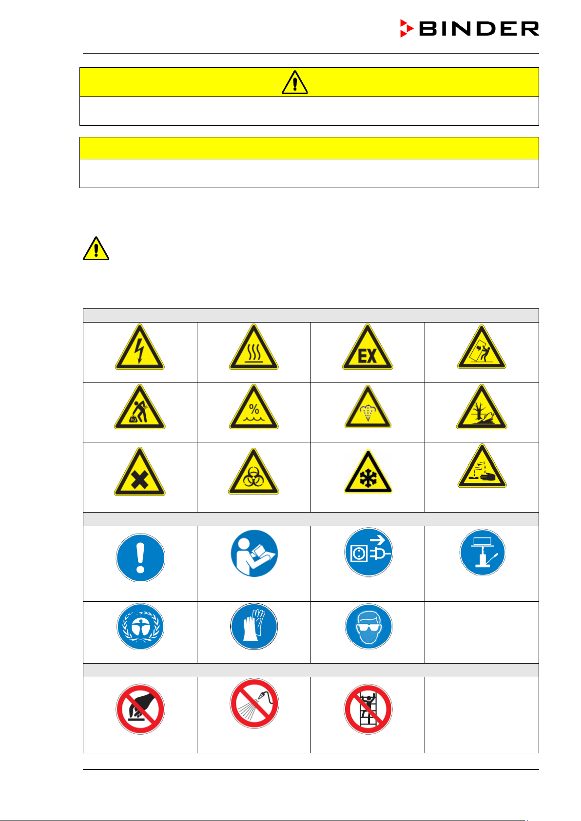
Warning signs
Electrical hazard
Hot surface
Explosive atmosphere
Lifting hazard
High humidity
Pollution hzard
or chemical burns
Mandatory action signs
instructions
plug
Environment protection
Wear protective gloves
Prohibition signs
water
CAUTION
Indicates a potentially hazardous situation which, if not avoided, may result in moderate or minor
(reversible) injury
CAUTION
Indicates a potentially hazardous situation which, if not avoided, may result in damage to the product
and/or its functions or of a property in its proximity.
1.2.2 Safety alert symbol
Use of the safety alert symbol indicates a risk of injury.
Observe all measures that are marked with the safety alert symbol in order to avoid death or
injury.
1.2.3 Pictograms
Harmful substances
Mandatory regulation
Biohazard
Read operating
Scalding hazard
Danger of frost
Disconnect the power
Wear safety goggles
Stability hazard
Risk of corrosion and /
Lift with mechanical
assistance
MKF + MKFT (E3.1) 04/2013 page 13/105
Do NOT touch
Do NOT spray with
Do NOT climb
Pictograms (Warning signs)
Service label
Information to be observed in order to ensure optimum function of the product.
1.2.4 Word message panel structure
Type / cause of hazard.
Possible consequences.
∅ Instruction how to avoid the hazard: prohibition
Instruction how to avoid the hazard: mandatory action
Observe all other notes and information not necessarily emphasized in the same way, in order to avoid
disruptions that could result in direct or indirect injury or property damage.
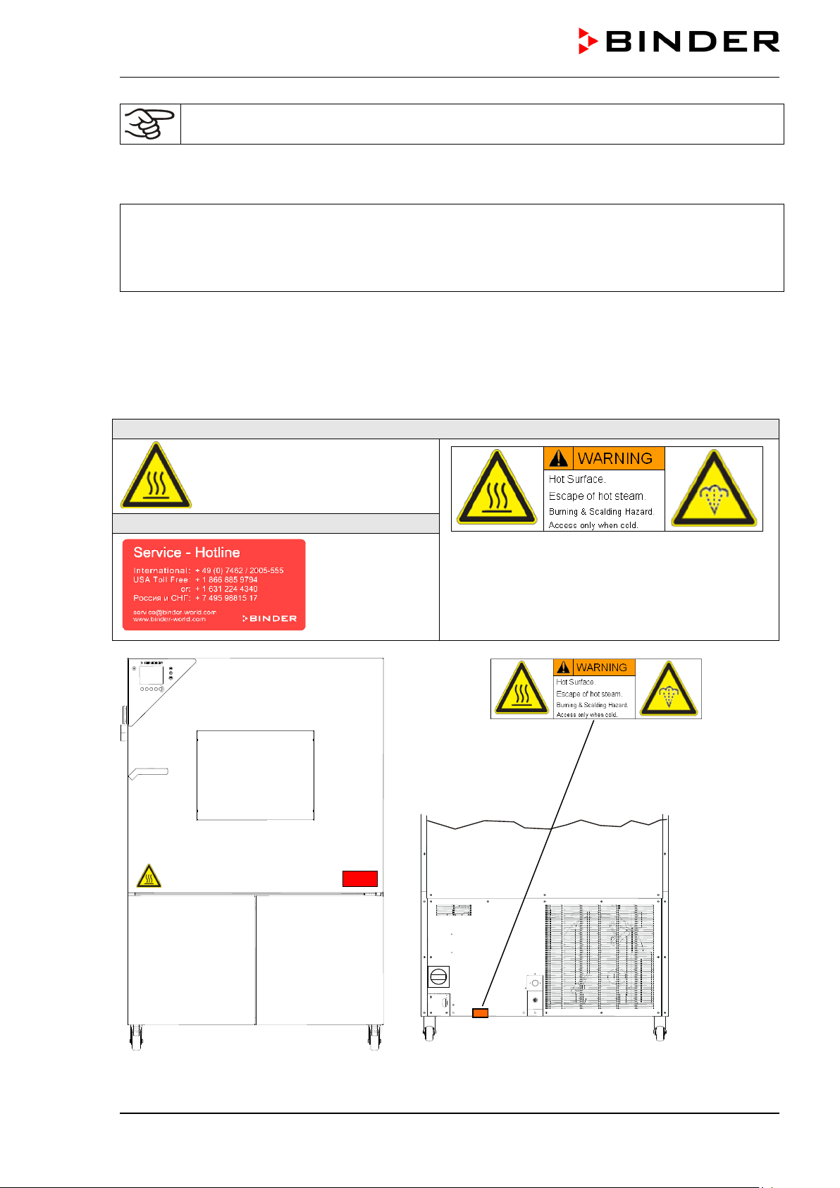
1.3 Localization / position of safety labels on the unit
The following labels are located on the unit:
Hot surface
Burning and scalding hazard
MKF + MKFT (E3.1) 04/2013 page 14/105
Figure 1: Position of labels on the unit
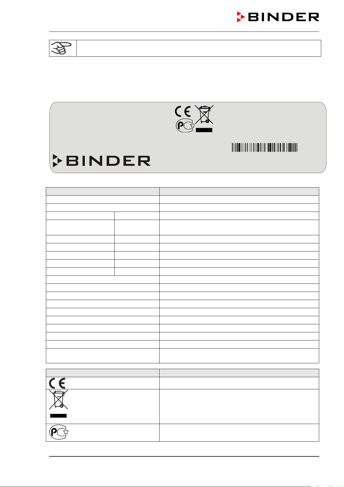
Indications of the type plate (example)
Information
BINDER
Manufacturer: BINDER GmbH
MKF 240
Model MKF 240
Serial No.
00-00000
Serial No. 00-00000
Nominal temperature
180 °C
356°F
Nominal temperature
Enclosure protection
IP 20
IP type of protection 20 acc. to EN 60529
Temp. safety device
DIN 12880
Temperature safety device acc. to standard DIN 12880
Class
2.0
Temperature safety device, class 2.0
Art. No.
9020-0183
Art. No. 9020-0183
Project No.
---
(Special application acc. to project no.)
6,80 kW
Nominal power 6.80 kW
400 V 3 N ~
Nominal voltage 400 V (+/-10%), three-phase unit
11,5 A
Nominal current 11.5 Amp
50 Hz
Power frequency 50 Hz
Max operating pressure 29 bar
Max operating pressure 29 bar in the refrigerating system
Stage 1
Cooling 1st stage
Stage 2
Cooling 2nd stage
R 404A – 2,20 kg
Refrigerant type R 404 A, filling weight: 2.20 kg
R 23 – 0,40 kg
Refrigerant type R 23, filling weight: 0.40 kg
Contains fluorinated greenhouse gases
covered by the Kyoto Protocol
Contains fluorinated greenhouse gases covered by the
Kyoto Protocol
Symbol on the type plate
Information
CE conformity marking
Electrical and electronic equipment manufactured / placed
(WEEE).
The equipment is certified in the GOST R certification sys-
Nominal temperature
180 °C
7,50 kW
Max operating pressure 29 BAR
356°F
400 V 3 N ~
Stage 1: R 404 A - 2,20 kg
Temp. safety device
IP 20
DIN 12880
50 Hz
Contains fluorinated greenhouse gases
Class
2.0 covered by the Kyoto Protocol
Art. No.
9020-0080
US PATS 4585923 / 5222612 / 5309981
D 78532 Tuttlingen / Germany
Internet: www.binder-world.com
Keep safety labels complete and legible.
Replace safety labels that are no longer legible. Contact BINDER service for these replacements.
1.4 Type plate
The type plate sticks to the left side of the unit, bottom right-hand, above the refrigerating and humidity
module.
Enclosure protection
Project No.
12,5 A
5405194 / 5601143 / 5773287 / 6079403
Tel. + 49 (0) 7462/ 2005-0
Stage 2: R 23 - 0,40 kg
MKFT 240 Serial No. 00-00000
Figure 2: Type plate (example of MKFT 240 regular unit)
Made in Germany
MKF + MKFT (E3.1) 04/2013 page 15/105
on the market in the EC after 13 August 2005 and be disposed of in separate collection according to the directive
2002/96/EC on waste electrical and electronic equipment
tem of GOSTSTANDARD Russia.
1.5 General safety instructions on installing and operating the environmental
simulation chamber MKF / MKFT
With regard to operating the environmental simulation chamber MKF / MKFT and to the installation location, please observe the guideline BGI/GUV-I 850-0 on safe working in laboratories (formerly BGR/GUVR 120 or ZH 1/119 laboratory guidelines issued by the employers’ liability insurance association) (for
Germany).
BINDER GmbH is only responsible for the safety features of the unit provided skilled electricians or qualified personnel authorized by BINDER perform all maintenance and repair, and if components relating to
chamber safety are replaced in the event of failure with original spare parts.
To operate the unit, use only original BINDER accessories or accessories from third-party suppliers authorized by BINDER. The user is responsible for any risk caused by using unauthorized accessories.
CAUTION
Danger of overheating.
Damage to the unit.
∅ Do NOT install the unit in unventilated recesses.
Ensure sufficient ventilation for dispersal of the heat.
Do not operate the environmental simulation chamber MKF / MKFT in hazardous locations.
DANGER
Explosion hazard.
Danger of death.
∅ Do NOT operate the unit in potentially explosive areas.
∅ KEEP explosive dust or air-solvent mixtures AWAY from the unit.
The environmental simulation chamber MKF / MKFT does not dispose of any measures of explosion protection.
DANGER
Explosion hazard.
Danger of death.
∅ Do NOT introduce any substance combustible or explosive at working temperature into
the environmental simulation chamber.
∅ NO explosive dust or air-solvent mixture in the inner chamber.
Any solvent contained in the charging material must not be explosive or inflammable. I.e., irrespective of
the solvent concentration in the steam room, NO explosive mixture with air must form. The temperature
inside the chamber must lie below the flash point or below the sublimation point of the charging material.
Familiarize yourself with the physical and chemical properties of the charging material, as well as the
contained moisture constituent and its behavior with the addition of heat energy and humidity.
Familiarize yourself with any potential health risks caused by the charging material, a possibly contained
moisture constituent or by reaction products that may arise during the conditioning process. Take adequate measures to exclude such risks prior to putting the environmental simulation chamber into operation.
MKF + MKFT (E3.1) 04/2013 page 16/105
DANGER
Electrical hazard.
Danger of death.
∅ The unit must NOT become wet during operation or maintenance.
The environmental simulation chambers were produced in accordance with VDE regulations and were
routinely tested in accordance to VDE 0411-1 (IEC 61010-1).
CAUTION
The window, the access ports and the inner chamber will become hot during operation.
Danger of burning.
∅ Do NOT touch the window, the access ports, the inner surfaces or the charging material
during operation.
WARNING
Stability hazard.
Danger of injury.
Damage to the unit and the charging material.
Housing cover breakaway.
∅ Do NOT climb on the lower housing cover.
∅ Do NOT load the lower housing cover with heavy objects while the unit door is open.
1.6 Intended use
Environmental simulation chambers series MKF / MKFT are suitable for temperature drying and heat
treatment of solid or pulverized charging material, as well as bulk material, using the supply of heat. They
are suitable for harmless materials. A mixture of any component of the charging material with air must
NOT be explosive. The operating temperature must lie below the flash point or below the sublimation
point of the charging material.
Other applications are not approved.
Observing the instructions in this operating manual and conducting regular maintenance work
(chap. 17) is part of the intended use.
DANGER
Explosion hazard.
Danger of death.
∅ Do NOT introduce any substance combustible or explosive at working temperature into
the climatic chamber.
∅ NO explosive dust or air-solvent mixture in the inner chamber.
The charging material shall not contain any corrosive ingredients that may damage the machine components made of stainless steel, aluminum, and copper. Such ingredients include in
particular acids and halides. Any corrosive damage caused by such ingredients is excluded
from liability by BINDER GmbH.
MKF + MKFT (E3.1) 04/2013 page 17/105
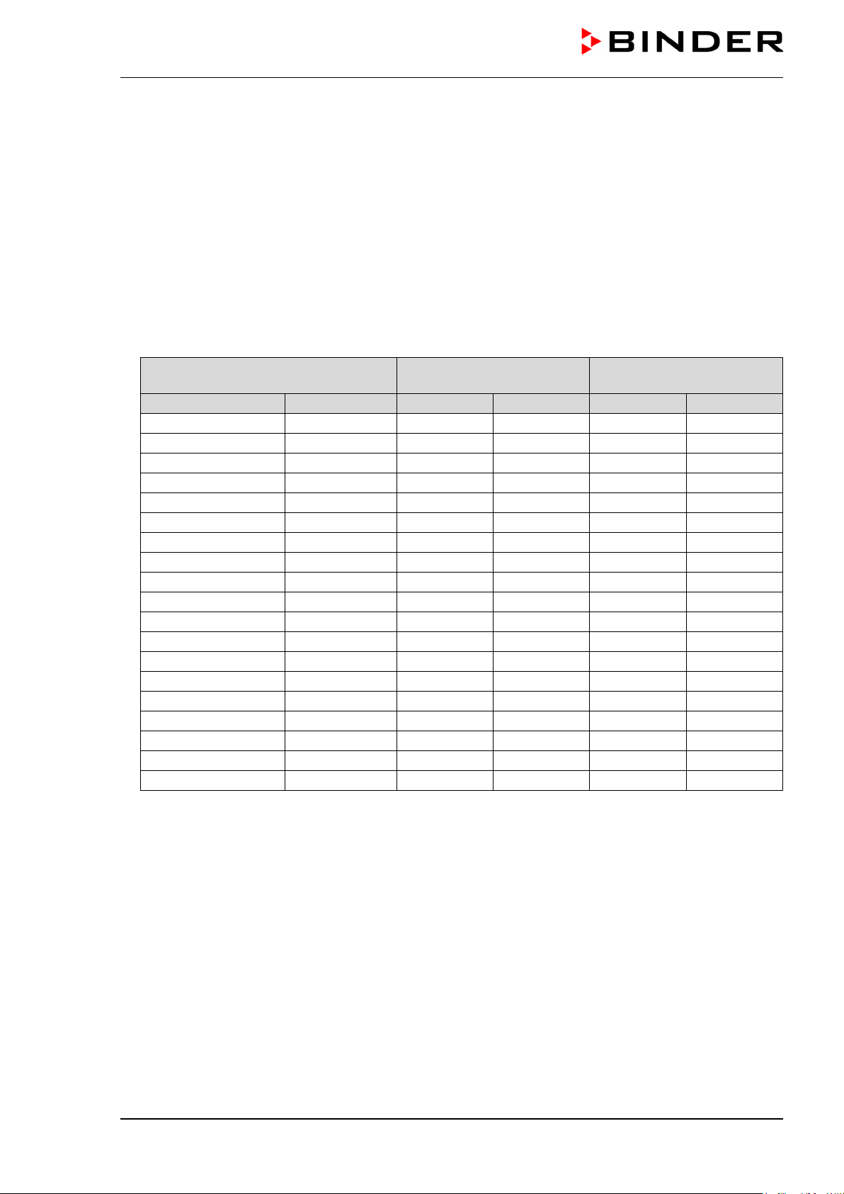
Maximum work place
threshold limit value
Tolerated concentration
with permanent load
Substance
Formula
ppm
mg/m3
ppm
mg/m3
Ammonia
NH3
20
14
5500
4000
Acetone
CH3COCH3
500
1200
3300
8000
Benzene
300
1200
150000
Chlorine
Cl2
0.5
1.5
0.7
2
Acetic acid
CH3COOH
10
25
800
2000
Ethyl acetate
CH3COOC2H5
400
1400
4000
15000
Ethanol
C2H5OH
500
960
3500
6000
Ethylene glycol
HOCH2CH2OH
10
26
1200
3000
Formaldehyde
HCHO
0.3
0.37
2400
3000
Isopropanol
(CH3)2CHOH
200
500
4800
12000
Methanol
CH3OH
200
260
3500
6000
Methyl ethyl ketone
C2H5COCH3
200
590
3300
8000
Ozone
O3
0.1
0.2
0.5
1
Hydrochloric acid
HCl 2 3
300
500
Hydrogen sulphide
H2S
10
15
350
500
Nitrogen oxides
NOx 5 9 5 9
Sulphur dioxide
SO2 5 13 5 13
Toluol
C6H5CH3
100
380
1300
5000
Xylene
C6H5(CH3)2
100
440
1300
5000
1.7 Resistance of the humidity sensor against harmful substances
The following list of harmful substances refers only to the humidity sensor and does not include any other
materials incorporated in the unit or prohibited substances in relation to explosion protection.
Some gases - especially clean gases - do not have any influence on the humidity sensor. Others do have
a very small influence, whereas others may influence the sensor to a larger extent.
• The following gases do not influence the sensor and the humidity measurement: Argon (Ar), carbon
dioxide (CO
• The following gases do not, or to a minor extent influence the sensor and the humidity measurement:
Butane (C
• The following gases do not, or to a minor extent influence the sensor and the humidity measurement,
provided that the indicated loads are not exceeded:
),helium (He), hydrogen (H2), neon (Ne), nitrogen (N2), nitrous oxide (N2O), oxygen (O2)
2
), ethane (C2H6), methane (CH4), natural gas propane (C3H8)
4H10
These values are to be considered only as approximate values. The sensor resistance largely depends on the temperature and humidity conditions during the time of exposure to harmful substances.
Avoid simultaneous condensation. Tolerated error of measurement: ± 2 % r.H. The maximum work
place threshold limit value is the one that can be regarded as harmless for humans.
• Vapors of oil and fat are dangerous for the sensor because they may condensate at the sensor and
thus prevent its function (insulating layer). For similar reasons it is not possible to measure smoke
gases.
MKF + MKFT (E3.1) 04/2013 page 18/105

2. Unit description
The environmental simulation chamber MKF / MKFT is a specially developed precision cooling/warming
cabinet for the domain of industrial material testing and environment simulation, with an unrivalled capacity, which far exceeds the capabilities of normal test cabinets, providing the ideal facilities for solving all
the problems which occur during material as well as ageing and stress tests.
The environmental simulation chambers MKF / MKFT are equipped with a multifunctional microprocessor
display controller with 2-channel technology for temperature and humidity plus a digital display accurate
to one-tenth of a degree resp. 0.1% r.H. With its comprehensive program control functions, the display
program controller MB1 permits the high precision performance of temperature and humidity cycles with
rapid heating up and cooling down phases.
With its microprocessor controlled humidifying and dehumidifying system the MKF / MKFT is a highprecision climatic test chamber. It covers the regular test specifications for temperature and climates corresponding to DIN und IEC standards. Furthermore, it permits simulating exactly and over long periods
constant conditions for other applications such as sample conditioning for material testing of paper, textiles, plastics, building materials, etc.
The patented APT.line™ preheating chamber and air conduction technology guarantees excellent spatial
temperature and humidity values for the total working area. The environmental simulation chamber MKF /
MKFT provides a powerful refrigerating system with rapid cooling-down speeds. In addition, the environmental simulation chamber MKF / MKFT provides almost unlimited possibilities for adaptation to individual customer requirements based upon extensive programming options.
A resistance humidifying system humidifies the air. For this purpose, use deionized (demineralized) water. The option BINDER Pure Aqua Service permits using the chamber with any degree of water hardness.
The inner chamber, the pre-heating chamber and the interior side of the doors are all made of stainless
steel (material no. 1.4301 in Germany). When operating the chamber at temperatures above 150 °C /
302°F, the impact of the oxygen in the air may cause discoloration of the metallic surfaces (yellowishbrown or blue) by natural oxidation processes. These colorations are harmless and will in no way impair
the function or quality of the unit. The housing is RAL 7035 powder-coated. All corners and edges are
completely coated.
The efficient program controller is equipped with a multitude of operating functions, in addition to recorder
and alarm functions. Programming of test cycles is easily accomplished via the modern color-display controller MB1 and is also possible directly with a computer via Intranet in connection with the communication
software APT-COM™ 3 DataControlSystem (option, chap. 16.1). The environmental simulation chamber
MKF / MKFT comes equipped with an Ethernet serial interface for computer communication. In addition,
the BINDER communication software APT-COM (option) permits networking up to 30 units and connecting them to a PC for controlling and programming, as well as recording and representing temperature and
humidity data. For further options, see chap. 20.6.
The environmental simulation chambers MKF / MKFT are equipped with
can be easily locked via the attached brakes.
• Temperature range MKF: without humidity -40 °C / 104 °F up to +180 ºC / 356 °F, in climatic operation
+ 10 °C / 50 °F up to +95 °C / 203 °F
• Temperature range MKFT: without humidity -70 °C / -94 °F up to +180 ºC / 356 °F, in climatic operation
+ 10 °C / 50 °F up to +95 °C / 203 °F
four castors. Both front castors
• Humidity range MKF / MKFT: 10% up to 98% r.H.
MKF + MKFT (E3.1) 04/2013 page 19/105
(A)
(F)
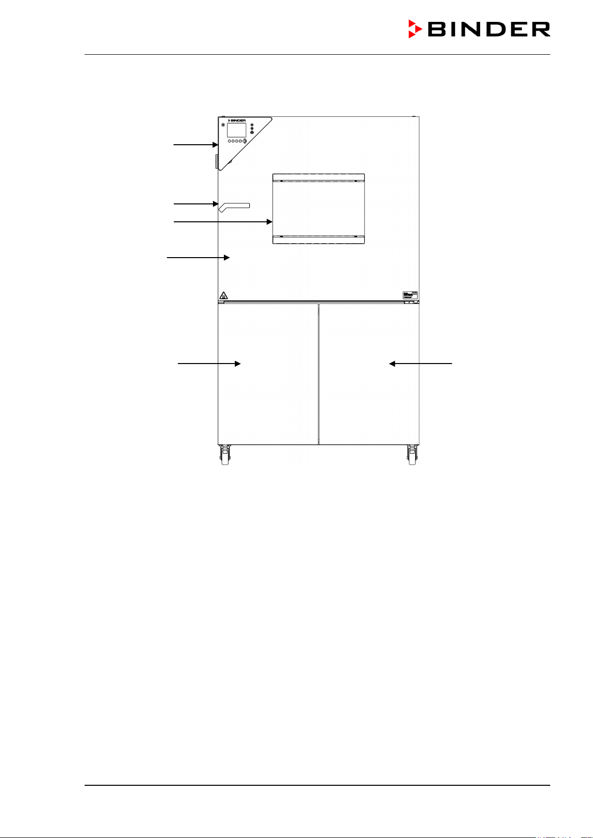
2.1 Unit overview
(B)
(C)
(D)
(E)
Figure 3: Environmental simulation chamber MKF / MKFT
(A) Instrument panel
(B) Door handle
(C) Window
(D) Door
(E) Refrigeration machine
(F) Access to fill the water can and to the humidity generation module
MKF + MKFT (E3.1) 04/2013 page 20/105
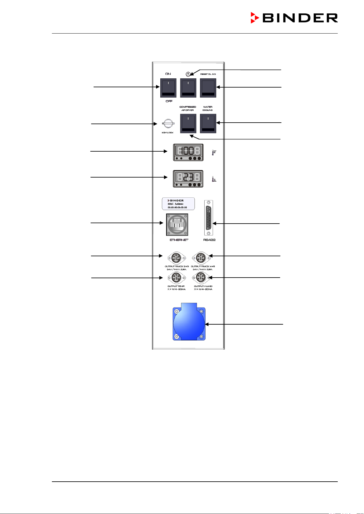
2.2 Lateral control panel
(3)
(6)
(9a)
(9b)
(10a)
(11)
(13)
(4)
(5)
(7)
(8)
(10b)
(12)
(14)
(15)
Figure 4: Lateral control panel MKF / MKFT at the right side of the humidity module with options
(3) Main power switch ON/OFF
(4) Humidity switch ON/OFF
(5) Reset switch for over and under temperature safety device class 2 (option)
(6) Key switch for keyboard locking (option)
(7) Switch for water cooling (only with MKF / MKFT 115 and 240) (option)
(8) Switch for compressed air dryer (option)
(9) Temperature safety device class 2 for over and under temperature (option):
Entry displays for upper (9a) and lower (9b) temperature limit
(10a) Ethernet interface for computer communication
(10b) RS422 interface for computer communication (option)
(11) 2 zero-voltage relay outputs via operation lines 2 and 3
(12) 2 zero-voltage relay outputs via operation lines 4 and 5
(13) Analog output temperature (option)
(14) Analog output humidity (option)
(15) Socket 230 V AC, max. 500 W
MKF + MKFT (E3.1) 04/2013 page 21/105
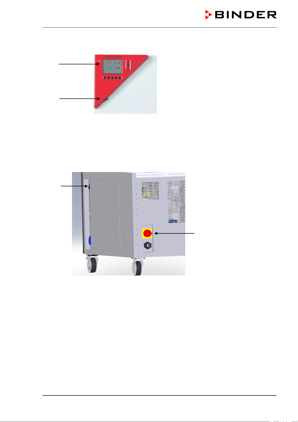
2.3 Instrument panel
(1)
(2)
(1) Microprocessor program controller MB1 with 2-channel technology for temperature and humidity
(2) Switch for interior chamber light
Figure 5: Triangle instrument panel
2.4 Rear power switch
(3)
(20)
Figure 6: Rear view MKF / MKFT
(3) Main power switch
(20) Rear power switch
MKF + MKFT (E3.1) 04/2013 page 22/105
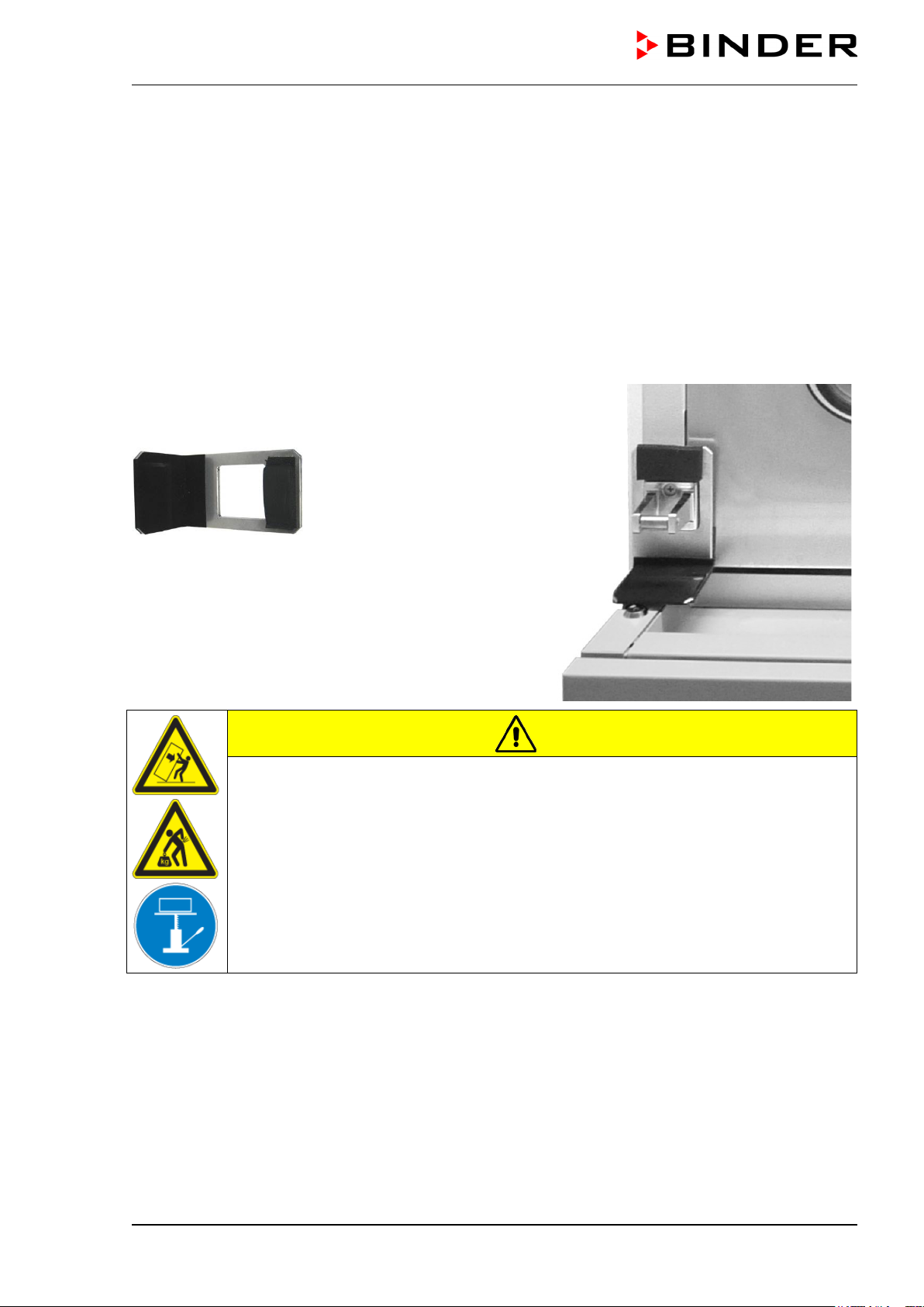
Remove the upholstered transport piece (L-type profile)
from the lower door locking and keep it for possible later
3. Completeness of delivery, transportation, storage, and installa-
tion
3.1 Unpacking, and checking equipment and completeness of delivery
After unpacking, please check the unit and its optional accessories, if any, based on the delivery receipt
for completeness and for transportation damage. Inform the carrier immediately if transportation damage
has occurred.
The final tests of the manufacturer may have caused traces of the shelves on the inner surfaces. This has
no impact on the function and performance of the unit.
Please remove any transportation protection devices and adhesives in/on the unit and on the doors and
take out the operating manuals and accessory equipment.
transportation.
Figure 7:
Door locking with transport piece (state of delivery)
CAUTION
Sliding or tilting of the unit.
Damage to the unit.
Risk of injury by lifting heavy loads.
∅ Do NOT lift or transport the unit using the door handle, the door or the lower housing.
∅ Do NOT lift the unit by hand.
Lift the unit from the pallet using technical devices (fork lifter). Set the fork lifter only
from the rear in the middle of the unit. Make sure to place all the lateral supports of the
unit on the forks.
If you need to return the unit, please use the original packing and observe the guidelines for safe lifting
and transportation (chap. 3.2).
For disposal of the transport packing, see chap. 18.1.
Note on second-hand units (Ex-Demo-Units)
Second-hand units are units that have been used for a short time for tests or exhibitions. They are thor-
oughly tested before resale. BINDER ensures that the chamber is technically sound and will work flawlessly.
Second-hand units are marked with a sticker on the unit door. Please remove the sticker before commissioning the unit.
MKF + MKFT (E3.1) 04/2013 page 23/105

3.2 Guidelines for safe lifting and transportation
The front castors can be blocked by brakes. Please move the units with castors only when empty and on
an even surface, otherwise the castors may be damaged. Mount the upholstered steel L-type profile at
the lower door locking. After operation please observe the guidelines for temporarily decommissioning the
unit (chap. 18.2).
CAUTION
Sliding or tilting of the unit.
Damage to the unit.
Risk of injury by lifting heavy loads.
Transport the unit only in its original packaging.
Secure the environmental simulation chamber with transport straps for transport.
∅ Do NOT lift or transport the unit using the door handle, the door or at the lower hous-
ing.
∅ Do NOT lift the unit by hand.
Place the unit using technical devices (fork lifter) on the transport pallet. Set the fork
lifter only from the rear in the middle of the unit. Make sure to place all the lateral sup-
ports of the unit on the forks.
Transport the unit with the original transport pallet. Set the fork lifter ONLY to the pal-
let. Without the pallet the unit is in imminent danger of overturning.
You can order transport packing and pallets for transportation purposes from BINDER service.
Permissible ambient temperature range during transport:
• If the steam humidifying system has NOT been emptied: +3 °C / 37.4 °F to +60 °C / 140 °F.
• After BINDER Service has emptied the steam humidifying system: -10 °C / 14 °F to +60 °C / 140 °F.
With temperatures below +3 °C / 37.4°F, water must be completely removed from the humidifying system.
CAUTION
Transport below +3 °C / 37.4°F with filled steam humidifying system.
Freezing in the steam generator.
Damage to the unit.
Contact BINDER Service before any transportation below +3 °C / 37.4°F.
3.3 Storage
Intermediate storage of the unit is possible in a closed and dry room. Observe the guidelines for temporary decommissioning (chap. 18.2).
Permissible ambient temperature range during storage:
• If the steam humidifying system has NOT been emptied: +3 °C / 37.4 °F to +60 °C / 140 °F.
• After BINDER Service has emptied the steam humidifying system: -10 °C / 14 °F to +60 °C / 140 °F.
MKF + MKFT (E3.1) 04/2013 page 24/105
CAUTION
CAUTION
d close the tap of the
With temperatures below +3 °C / 37.4 °F, water must be completely removed from the humidifying sys-
tem.
Storage below +3 °C / 37.4 °F with filled steam humidifying system.
Freezing in the steam generator.
Damage to the unit.
Contact BINDER Service before any storage below +3 °C / 37.4 °F.
• Permissible ambient humidity: max. 70 % r.H., non-condensing
Condensation by excess humidity.
Danger of corrosion on the housing after operating at humidity values > 70 % r.H.
for a long period.
Dry the appliance completely before shut-down:
• Set the humidity to 0 % r.H. or turn off humidity switch (4).
• Set the temperature set point to 150 °C / 302 °F (Manual mode). Let the unit oper-
ate for approx. 2-3 hours with closed door. Remove the access port plugs.
• Only then, shut down the unit at the main power switch (3) an
water supply.
After drying the unit for decommissioning, the humidity value will approximate ambient humidity.
When after storage in a cold location you transfer the unit to its warmer installation site, condensation
may form. Before start-up, wait at least two hours until the chamber has attained ambient temperature
and is completely dry and the oil in the compressors has warmed up.
In case of a prolonged temporal decommissioning: Leave the unit door open or remove the access port
plugs.
3.4 Location of installation and ambient conditions
Set up the environmental simulation chamber on a flat, even surface, and in a well-ventilated, dry location
and align it using a spirit level. The site of installation must be capable of supporting the unit’s weight (see
technical data, chap. 20.4). The chambers are designed for setting up inside a building (indoor use).
When after storage in a cold location you transfer the unit to its warmer installation site, condensation
may form. Before start-up, wait at least two hours until the chamber has attained ambient temperature
and is completely dry and the oil in the compressors has warmed up.
CAUTION
Danger of overheating.
Damage to the unit.
∅ Do NOT set up units in non-ventilated recesses.
Ensure sufficient ventilation for dispersal of the heat.
• Permissible ambient temperature range during operation: +18 °C / 64.4 °F to +32 °C / 89.6 °F. At
elevated ambient temperature values, fluctuations in temperature can occur.
The ambient temperature should not be substantially higher than the indicated ambient temperature of +25 °C / 77°F to which the specified technical data relate. For other ambient conditions, deviations from the indicated data are possible.
MKF + MKFT (E3.1) 04/2013 page 25/105
CAUTION
• Permissible ambient humidity: 70 % r.H. max., non-condensing.
When operating the chamber at temperature set-points below ambient temperature, high ambient humidity may lead to condensation on the unit.
• Installation height: max. 2000 m / 6.6 ft. above sea level.
A water tap (1 bar to 10 bar) is necessary for the installation of the humidification system. If no suitable
house water connection is available, you can manually supply water by filling the water can (chap. 4.2).
When placing several units of the same size side by side, maintain a minimum distance of 250 mm / 9.84
in between each unit. Wall distances: rear 300 mm / 11.81 in, sides 200 mm / 7.87 in. Spacing above the
unit of at least 200 mm / 7.87 in must also be accounted for.
Danger by stacking.
Damage to the units.
∅ Do NOT place environmental simulation chambers on top of each other.
To completely separate the unit from the power supply, you must disconnect the power plug. Install the
unit in a way that the power plug is easily accessible and can be easily pulled in case of danger.
With an increased amount of dust in the ambient air, clean the condenser fan several times a year. We
recommend checking the fan grid (behind the left maintenance access flap) every week. In case of visible
dirt accumulation, disconnect the unit and clean the fan grid by suction.
Avoid any conductive dust in the ambiance according to the unit layout complying with pollution degree 2
(IEC 61010-1).
The environmental simulation chamber MKF / MKFT must not be installed and operated in potentially
explosive areas.
DANGER
Explosion hazard.
Danger of death.
∅ Do NOT operate the unit in potentially explosive areas.
∅ KEEP explosive dust or air-solvent mixtures AWAY from the vicinity of the unit.
MKF + MKFT (E3.1) 04/2013 page 26/105
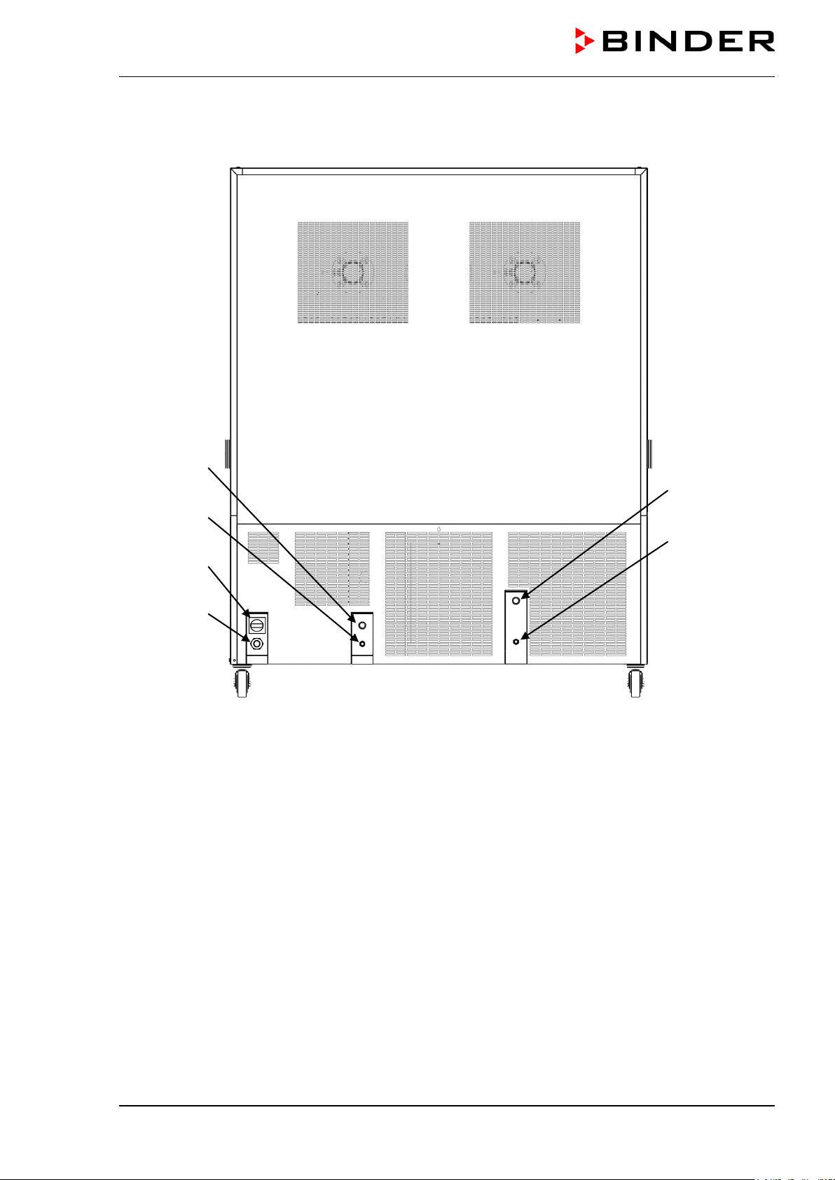
4. Installation and connections
(18)
(17)
(20)
(21)
(22)
(16)
Figure 8: Rear view MKF / MKFT with water connections and optional water cooling
(16) Power cable
(17) Wastewater connection “OUT” with hose olive for hose ½“
(18) Freshwater connection “IN” with screw thread ¾’’ for hose ½“, with union nut
(20) Rear power switch
(21) Connection “OUT” for cooling water outlet with screw thread ¾’’ for hose ½“, with union nut (option
water cooling)
(22) Connection “IN” for cooling water inlet with screw thread ¾’’ for hose ½“, with union nut (option
water cooling)
MKF + MKFT (E3.1) 04/2013 page 27/105
4.1 Wastewater connection for humidifying system
Fasten the wastewater hose to the wastewater connection “OUT” (17) (Figure 8) on the rear of the unit
(olive ∅ 14 mm). Observe the following points:
• You can use a part of the supplied tap water hose as a drainage hose. In case another hose is used, it
has to be permanently resistant against at least 95 °C / 203 °F.
• Mount the wastewater hose with a maximum positive inclination of 1 m and a maximum total length of
3 m.
• Protect both ends of the drainage hose with two of the four supplied hose clamps.
Wastewater is collected in an internal can with a volume of approx. 0.5 liters. It is pumped off
only when required, thus there is no continuous wastewater flow.
Protect the wastewater supply at both sides with the supplied hose clamps.
4.2 Freshwater supply for humidifying system
Connect the wastewater pipe before connecting the unit to a freshwater pipe or filling the water can.
You can supply the unit with freshwater via a water pipe or by manually filling the internal water can. It is
not necessary to switch between both possibilities. When connecting to a water pipe, the water can is
automatically filled.
Water intake temperature NOT below +5 °C / 41 °F and not exceeding 40 °C / 104 °F.
CAUTION
Calcification of the humidifying system.
Damage to the unit.
Operate the unit with deionized (demineralized) water only.
Types of suitable water quality
• Deionized water from a water treatment installation already existing at the customer's site. Conductivity from 1 µS /cm up to a maximum of 20 µS/cm. (Water, which is in equilibrium with the CO
and has a conductivity below 1 µS/cm (ultrapure water), may cause acid corrosion due to its low pH.)
• Water treated by the optional water treatment system BINDER Pure Aqua Service (disposable system). A reusable measuring equipment to assess the water quality is included (chap. 16.7).
in the air,
2
BINDER GmbH is NOT responsible for the water quality at the user’s site.
Any problems and malfunctions that might arise following use of water of deviating quality is
excluded from liability by BINDER GmbH.
The warranty becomes void in the event of use of water of deviating quality.
MKF + MKFT (E3.1) 04/2013 page 28/105
delivered adapter with hose olive on the thread at the rear of
4.2.1 Automatic fresh water supply for humidifying system via water pipe
An enclosure inside the unit contains the connection kit for water supply and wastewater. Install the water
supply connection using either the enclosed water hose or another pressure-resistant one. To accomplish
this, remove the cover of the freshwater connection “IN” (18) (Figure 8) on the rear of the unit. Protect
both ends of the hose with two of the four supplied hose clamps. Before turning on the unit, check the
connection for leaks. Water supply is automatically effected via the freshwater connection “IN” (18).
As the unit only lets in water when required, there is no continuous water flow.
• Supply pressure 1 to 10 bar when connecting to a water pipe.
• Water type: deionized (demineralized) water
• Water intake temperature NOT below +5 °C / 41 °F and not exceeding 40 °C / 104 °F.
• The water intake shall be provided with a shut-off slide or water-tap.
• For the water supply, fix the
the chamber.
• Protect the water supply at one side with the supplied hose clamp.
4.2.2 Manual fresh water supply for humidifying system via internal freshwater can
If no house water connection with suitable water is available, you can manually supply water by filling the
freshwater can (total volume: 19 liters / 0.67 cu.ft. up to the maximum level mark), which is located behind
the right door of the humidity generation module.
The cover of the water inlet valve must be screwed on the freshwater connection “IN” (18). Open the door
(F) (Figure 3) to access the filler neck of one of the water can. You cannot totally take out the water can
because of its fix connections. Fill the water can only up to ¾, up to the maximum level mark. When filling
it too much with the chamber turned on, the alarm message “
controller (chap. 13.1). Manually suck off the water, or operate the unit with high temperature and humidity values until the excess water is consumed. When filling it too much with the chamber turned off, water
can escape from the unit. Thus, ensure not to fill the can by more than the maximum level mark.
To guarantee humidification during 24 hours even at high humidity set-points with manual
water supply, we recommend filling the freshwater can (option) daily at the end of the day.
WATER LEVEL TOO HIGH” is displayed on the
MKF + MKFT (E3.1) 04/2013 page 29/105
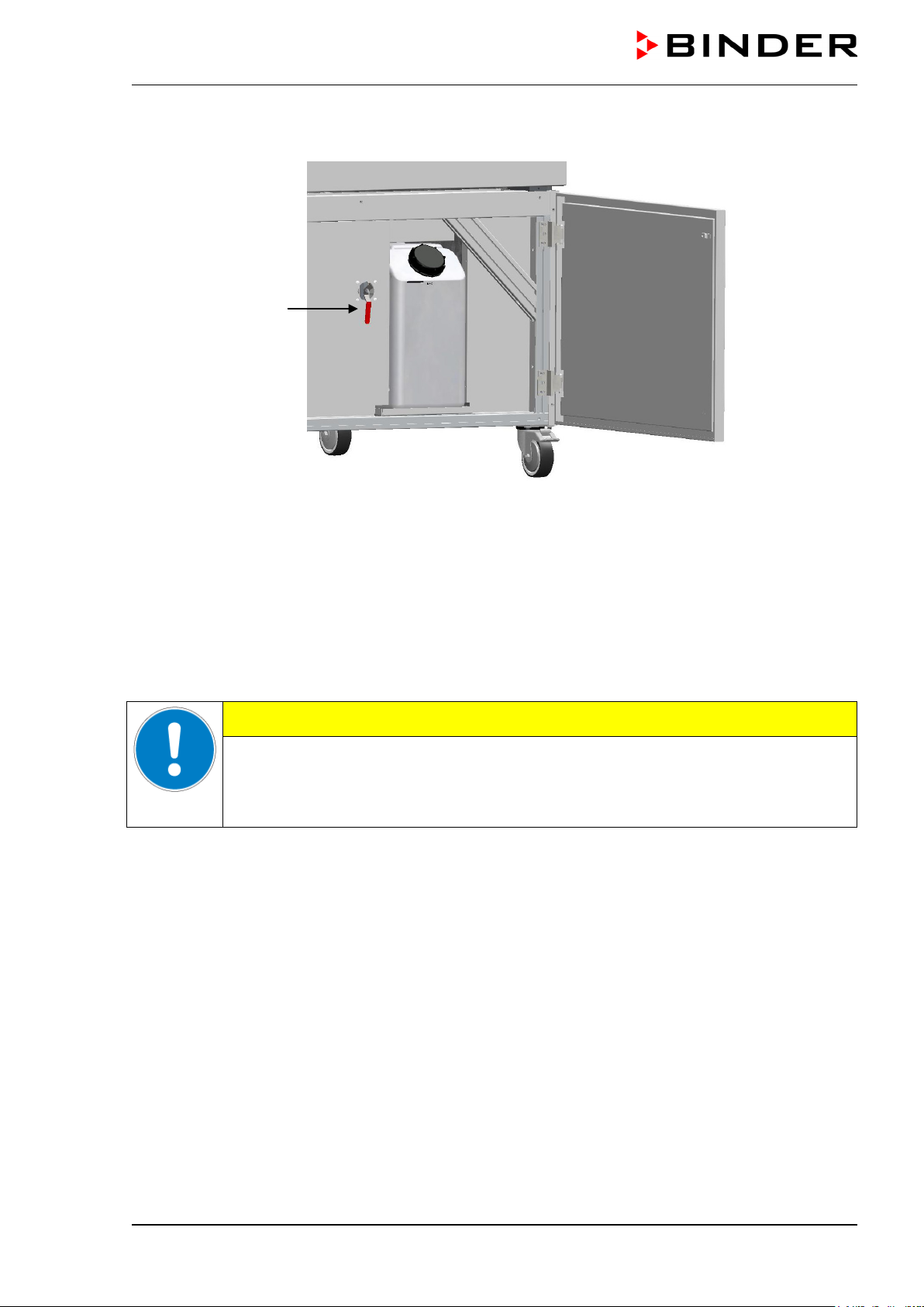
(19)
4.2.3 Water circle: lever for condensate recycling (option)
Figure 9: Lever for condensate recycling (open position)
next to the freshwater can behind the maintenance access door
The lever (19) for condensate recycling is located behind the maintenance access door next to the freshwater can.
• Open lever (vertical position): the condensate from the interior is conducted to the freshwater can. Use
only with clean interior!
• Closed lever (horizontal position): the condensate is conducted to the wastewater connection. Use this
position in case of soiling / contamination of the interior.
CAUTION
Soiling of the vapor humidification system.
Damage to the unit.
Conduct the condensate to the wastewater connection in case of soiling / contamina-
tion of the interior (horizontal lever position).
MKF + MKFT (E3.1) 04/2013 page 30/105
 Loading...