

Page 1
Model
Model version
Art. No.
Model
Model version
Art. No.
Operating Manual
Translation of the original operating manual
MK (E5)
Alternating climate chambers with program control
MK 56 MK056-230V 9020-0374, 9120-0374
MK056-240V 9020-0388, 9120-0388
MK 115
MK 240
MK 720
MK115-400V
MK115-400V-C 9020-0303 (with voltage and frequency changer)
MK240-400V
MK240-400V-C
MK720-400V
MK720-400V-C
9020-0375, 9120-0375
9020-0376, 9120-0376
9020-0355 (with voltage and frequency changer)
9020-0377, 9120-0377
9020-0356 (with voltage and frequency changer)
MKT (E5)
Alternating climate chambers with deep temperature
and program control
MKT 115
MKT 240
MKT 720
MKT115-400V
MKT115-400V-C
MKT240-400V
MKT240-400V-C
MKT720-400V
MKT720-400V-C
BINDER GmbH
9020-0385, 9120-0385
9020-0363 (with voltage and frequency changer)
9020-0386, 9120-0386
9020-0364 (with voltage and frequency changer)
9020-0387, 9120-0387
9020-0365 (with voltage and frequency changer)
Address: Post office box 102, 78502 Tuttlingen, Germany Phone: +49 7462 2005 0
Fax: +49 7462 2005 100 Internet: http://www.binder-world.com
E-mail: info@binder-world.com Service Hotline: +49 7462 2005 555
Service Fax: +49 7462 2005 93 555 Service E-Mail: service@binder-world.com
Service Hotline USA: +1 866 885 9794 or +1 631 224 4340 x3
Service Hotline Asia Pacific: +852 390 705 04 or +852 390 705 03
Service Hotline Russia and CIS: +7 495 988 15 16
Issue 03/2019 Art. no. 7001-0364
Page 2

Contents
1. SAFETY .................................................................................................................. 6
1.1 Legal considerations ........................................................................................................................... 6
1.2 Structure of the safety instructions ...................................................................................................... 6
1.2.1 Signal word panel ...................................................................................................................... 6
1.2.2 Safety alert symbol .................................................................................................................... 7
1.2.3 Pictograms ................................................................................................................................ 7
1.2.4 Word message panel structure ................................................................................................. 8
1.3 Localization / position of safety labels on the chamber ....................................................................... 8
1.4 Type plate ............................................................................................................................................ 9
1.5 General safety instructions on installing and operating the chamber ................................................ 10
1.6 Intended use ...................................................................................................................................... 12
1.7 Operating instructions ....................................................................................................................... 13
1.8 Measures to prevent accidents ......................................................................................................... 13
2. CHAMBER DESCRIPTION .................................................................................. 14
2.1 Chamber overview ............................................................................................................................ 15
2.2 Instrument panel................................................................................................................................ 15
2.3 Lateral control panel .......................................................................................................................... 16
2.4 Main power switch (MK 56) ............................................................................................................... 17
2.5 Rear power switch (MK / MKT 115, 240, 720) .................................................................................. 17
2.6 Rear chamber view ........................................................................................................................... 18
3. COMPLETENESS OF DELIVERY, TRANSPORTATION, STORAGE, AND
INSTALLATION .................................................................................................... 20
3.1 Unpacking, and checking equipment and completeness of delivery................................................. 20
3.2 Guidelines for safe lifting and transportation ..................................................................................... 21
3.3 Storage .............................................................................................................................................. 21
3.4 Location of installation and ambient conditions ................................................................................. 21
4. INSTALLATION AND CONNECTIONS ................................................................ 23
4.1 Connection of cooling water outlet for water cooling (option for MK 56) ........................................... 23
4.2 Connection of cooling water inlet for water cooling (option for MK 56) ............................................. 23
4.3 Installation of the voltage and frequency changer (chambers with voltage and frequency changer) 24
4.4 Electrical connection ......................................................................................................................... 26
4.4.1 Information on connecting the alternating climate chamber ................................................... 26
4.4.2 Connecting the voltage and frequency changer (for chambers equipped with a voltage and
frequency changer) ................................................................................................................. 27
5. FUNCTIONAL OVERVIEW OF THE MB2 CHAMBER CONTROLLER ............... 28
5.1 Operating functions in normal display ............................................................................................... 29
5.2 Display views: Normal display, program display, chart-recorder display ........................................... 30
5.3 Controller icons overview .................................................................................................................. 31
5.4 Operating modes ............................................................................................................................... 33
5.5 Controller menu structure .................................................................................................................. 34
5.5.1 Main menu .............................................................................................................................. 35
5.5.2 “Settings” submenu ................................................................................................................. 36
5.5.3 “Service” submenu .................................................................................................................. 36
5.6 Principle of controller entries ............................................................................................................. 37
5.7 Performance during and after power failures .................................................................................... 37
5.8 Performance when opening the door ................................................................................................ 38
6. START UP ............................................................................................................ 38
6.1 Turning on the chamber .................................................................................................................... 38
6.2 Controller settings upon start up ....................................................................................................... 39
MK / MKT (E5) 03/2019 page 2/158
Page 3

7. SET-POINT ENTRY IN “FIXED VALUE” OPERATING MODE ........................... 40
7.1 Set-point entry through the “Setpoints” menu ................................................................................... 40
7.2 Direct setpoint entry via Normal display ............................................................................................ 41
7.3 Special controller functions via operation lines ................................................................................. 41
8. TIMER PROGRAM: STOPWATCH FUNCTION ................................................... 43
8.1 Starting a timer program ................................................................................................................... 43
8.1.1 Performance during program delay time ................................................................................ 43
8.2 Stopping a running timer program ..................................................................................................... 44
8.2.1 Pausing a running timer program............................................................................................ 44
8.2.2 Cancelling a running timer program ........................................................................................ 44
8.3 Performance after the end of the program ........................................................................................ 44
9. TIME PROGRAMS ............................................................................................... 45
9.1 Starting an existing time program ..................................................................................................... 45
9.1.1 Performance during program delay time ................................................................................ 46
9.2 Stopping a running time program ...................................................................................................... 46
9.2.1 Pausing a running time program ............................................................................................. 46
9.2.2 Cancelling a running time program ......................................................................................... 46
9.3 Performance after the end of the program ........................................................................................ 46
9.4 Creating a new time program ............................................................................................................ 47
9.5 Program editor: program management ............................................................................................. 47
9.5.1 Deleting a time program .......................................................................................................... 48
9.6 Section editor: section management ................................................................................................. 49
9.6.1 Add a new program section .................................................................................................... 50
9.6.2 Copy and insert or replace a program section ........................................................................ 50
9.6.3 Deleting a program section ..................................................................................................... 51
9.7 Value entry for a program section ..................................................................................................... 52
9.7.1 Section duration ...................................................................................................................... 52
9.7.2 Set-point ramp and set-point step ........................................................................................... 53
9.7.3 Special controller functions via operation lines ....................................................................... 54
9.7.4 Setpoint entry .......................................................................................................................... 55
9.7.5 Tolerance range ...................................................................................................................... 56
9.7.6 Repeating one or several sections within a time program ...................................................... 57
9.7.7 Saving the time program ......................................................................................................... 57
10. WEEK PROGRAMS ............................................................................................. 58
10.1 Starting an existing week program .................................................................................................... 58
10.2 Cancelling a running week program .................................................................................................. 58
10.3 Creating a new week program .......................................................................................................... 59
10.4 Program editor: program management ............................................................................................. 60
10.4.1 Deleting a week program ........................................................................................................ 61
10.5 Section editor: section management ................................................................................................. 62
10.5.1 Add a new program section .................................................................................................... 63
10.5.2 Copy and insert or replace a program section ........................................................................ 63
10.5.3 Deleting a program section ..................................................................................................... 64
10.6 Value entry for a program section ..................................................................................................... 64
10.6.1 Set-point ramp and set-point step modes ............................................................................... 64
10.6.2 Weekday ................................................................................................................................. 65
10.6.3 Start time ................................................................................................................................. 65
10.6.4 Setpoint entry .......................................................................................................................... 66
10.6.5 Special controller functions via operation lines ....................................................................... 66
11. NOTIFICATION AND ALARM FUNCTIONS ........................................................ 67
11.1 Notification and alarm messages overview ....................................................................................... 67
11.1.1 Notifications ............................................................................................................................ 67
11.1.2 Alarm messages ..................................................................................................................... 68
MK / MKT (E5) 03/2019 page 3/158
Page 4

11.2
State of alarm .................................................................................................................................... 68
11.3 Resetting an alarm, list of active alarms ........................................................................................... 69
11.4 Activating / deactivating the audible alarm (alarm buzzer) ................................................................ 69
12. TEMPERATURE SAFETY DEVICES ................................................................... 70
12.1 Over temperature protective device (class 1) ................................................................................... 70
12.2 Overtemperature safety controller class 2 ........................................................................................ 70
12.2.1 Safety controller modes .......................................................................................................... 70
12.2.2 Setting the safety controller ..................................................................................................... 71
12.2.3 Message and measures in the state of alarm ......................................................................... 72
12.2.4 Function check ........................................................................................................................ 72
12.3 Over/under temperature safety device class 2 (option) .................................................................... 73
13. USER MANAGEMENT ......................................................................................... 74
13.1 Authorization levels and password protection ................................................................................... 74
13.2 Log in ................................................................................................................................................. 77
13.3 Log out .............................................................................................................................................. 78
13.4 User change ...................................................................................................................................... 78
13.5 Password assignment and password change ................................................................................... 79
13.5.1 Password change ................................................................................................................... 79
13.5.2 Deleting the password for an individual authorization level .................................................... 81
13.5.3 New password assignment for “Service” or “Admin” authorization level when the password
function was deactivated ......................................................................................................... 82
13.6 Activation code .................................................................................................................................. 83
14. GENERAL CONTROLLER SETTINGS ................................................................ 84
14.1 Selecting the controller’s menu language ......................................................................................... 84
14.2 Setting date and time ........................................................................................................................ 84
14.3 Selecting the temperature unit .......................................................................................................... 86
14.4 Display configuration ......................................................................................................................... 86
14.4.1 Adapting the display parameters............................................................................................. 86
14.4.2 Touchscreen calibration .......................................................................................................... 87
14.5 Network and communication ............................................................................................................. 88
14.5.1 Serial interfaces ...................................................................................................................... 88
14.5.2 Ethernet................................................................................................................................... 89
14.5.2.1 Configuration ................................................................................................................... 89
14.5.2.2 Display of MAC address .................................................................................................. 90
14.5.3 Web server ............................................................................................................................. 90
14.5.4 E-Mail ...................................................................................................................................... 91
14.6 USB menu: Data transfer via USB interface ..................................................................................... 92
14.7 Turning off the interior lighting automatically ..................................................................................... 93
15. GENERAL INFORMATION .................................................................................. 93
15.1 Service contact page ......................................................................................................................... 93
15.2 Current operating parameters ........................................................................................................... 94
15.3 Event list ............................................................................................................................................ 95
15.4 Technical chamber information ......................................................................................................... 95
15.5 Self-test function (MK 56) .................................................................................................................. 96
16. CHART RECORDER DISPLAY ............................................................................ 98
16.1 Views ................................................................................................................................................. 98
16.1.1 Show and hide legend ............................................................................................................. 98
16.1.2 Switch between legend pages ................................................................................................ 98
16.1.3 Show and hide specific indications ......................................................................................... 99
16.1.4 History display ......................................................................................................................... 99
16.2 Setting the parameters .................................................................................................................... 102
17. NOTES ON REFRIGERATING OPERATION .................................................... 103
MK / MKT (E5) 03/2019 page 4/158
Page 5

18. ANTI-CONDENSATION PROTECTION VIA OPERATION LINE ....................... 104
19. ZERO-VOLTAGE SWITCHING OUTPUTS VIA OPERATION LINES ............... 105
20. OPTIONS ............................................................................................................ 106
20.1 APT-COM™ 4 Multi Management Software (option) ...................................................................... 106
20.2 RS485 interface (option) ................................................................................................................. 106
20.3 Data logger kit (option) .................................................................................................................... 106
20.4 Analog outputs for temperature (option) ......................................................................................... 106
20.5 Compressed air connection (option) ............................................................................................... 107
20.6 Compressed air dryer (option)......................................................................................................... 107
20.7 Water cooling (option) ..................................................................................................................... 109
20.8 Object temperature display with flexible Pt 100 temperature sensor (option) ................................. 109
21. MAINTENANCE, CLEANING, AND SERVICE ................................................... 110
21.1 Maintenance intervals, service ........................................................................................................ 110
21.2 Cleaning and decontamination ........................................................................................................ 111
21.2.1 Cleaning ................................................................................................................................ 111
21.2.2 Decontamination ................................................................................................................... 113
21.3 Sending the chamber back to BINDER GmbH ............................................................................... 114
22. DISPOSAL .......................................................................................................... 114
22.1 Disposal of the transport packing .................................................................................................... 114
22.2 Decommissioning ............................................................................................................................ 115
22.3 Disposal of the chamber in the Federal Republic of Germany ........................................................ 115
22.4 Disposal of the chamber in the member states of the EU except for the Federal Republic of
Germany .......................................................................................................................................... 116
22.5 Disposal of the chamber in non-member states of the EU ............................................................. 117
23. TROUBLESHOOTING ....................................................................................... 118
24. TECHNICAL DESCRIPTION .............................................................................. 121
24.1 Factory calibration and adjustment ................................................................................................. 121
24.2 Over-current protection ................................................................................................................... 121
24.3 Definition of usable volume ............................................................................................................. 121
24.4 MK (E4) technical data .................................................................................................................... 122
24.5 MKT (E4) technical data .................................................................................................................. 124
24.6 Equipment and options (extract) ..................................................................................................... 126
24.7 Accessories and spare parts (extract)............................................................................................. 127
24.8 MK heating-up and cooling-down graphs ........................................................................................ 128
24.9 MKT heating-up and cooling-down graphs ...................................................................................... 132
24.10 MK heat compensation.................................................................................................................... 135
24.11 MKT heat compensation ................................................................................................................. 136
24.12 Dimensions...................................................................................................................................... 138
25. CERTIFICATES AND DECLARATIONS OF CONFORMITY ............................. 143
25.1 EU Declaration of Conformity for MK .............................................................................................. 143
25.2 EU Declaration of Conformity for MKT ............................................................................................ 146
25.3 Certificate for the GS mark of conformity of the “Deutsche Gesetzliche Unfallversicherung e.V.“
(German Social Accident Insurance) DGUV ................................................................................... 149
26. PRODUCT REGISTRATION .............................................................................. 151
26.1 Registering a BINDER chamber ..................................................................................................... 151
26.2 Multi Management Software APT-COM™ 4 BASIC-Edition ........................................................... 152
27. CONTAMINATION CLEARANCE CERTIFICATE .............................................. 153
27.1 For chambers located outside the USA and Canada ...................................................................... 153
27.2 For chambers located in the USA and Canada ............................................................................... 156
MK / MKT (E5) 03/2019 page 5/158
Page 6
Dear customer,
For the correct operation of the chambers, it is important that you read this operating manual c ompletely
and carefully and observe all instructions as indicated. Failure to read, understand and follow the instructions may result in personal injury. It can also lead to damage to the chamber and/or poor equipm ent performance.
1. Safety
This operating manual is part of the components of delivery. Always keep it handy for reference. The device should only be operated by laboratory personnel especially trained for this purpose and familiar with
all precautionary measures required f or working in a laborator y. Observe the national regulations on minimum age of laboratory personnel. To avoid injuries and damage obs erve the safety instructions of the
operating manual.
WARNING
Failure to observe the s afety instructions.
Serious injuries and chamber damage.
Observe the safety instructions in this operating manual
Carefully read the complete operating instructions of the chambers.
1.1 Legal considerations
This operating manual is for informational purposes only. It contains inform ation for installing, start-up,
operation and maintenance of the product. Note: the contents and the product described are s ubject to
change without notice.
Understanding and observing the instr uctions in this operating manual are prerequisites for hazard-free
use and safety during operation and maintenance. In no event shall BINDER be held liable for any damages, direct or incidental arising out of or related to the use of this manual.
This operating manual cannot cover all conc eivable applications. If you would like additional information,
or if special problems aris e that are not sufficiently addressed in this manual, please ask your dealer or
contact us directly by phone at the number located on page one of this manual
Furthermore, we emphas ize that the contents of this operat ing m anual ar e not part of an earlier or existing
agreement, description, or legal relationship, nor do they modif y such a relationship. All obligations on the
part of BINDER derive from the respective purchase c ontract, which also contains the entire and exclusively valid statement of warranty administration. The statements in this manual neither augment nor restrict the contractual warranty provisions.
1.2 Structure of the safety instructions
In this operating manual, the following safety definitions and symbols indicate dangerous situations following the harmonization of ISO 3864-2 and ANSI Z535.6.
1.2.1 Signal word panel
Depending on the probability of serious consequences, potential dangers are identified with a signal word,
the corresponding safety color, and if appropriate, the safety alert symbol.
DANGER
Indicates an imminently hazardous situation that, if not avoided, will result in death or serious
(irreversible) injury.
MK / MKT (E5) 03/2019 page 6/158
Page 7
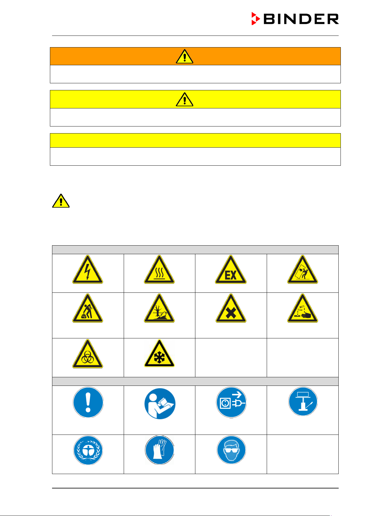
Warning signs
Electrical hazard
Hot surface
Explosive atmosphere
Stability hazard
or chemical burns
Biohazard
Mandatory action signs
instructions
Environment protection
WARNING
Indicates a potentially hazardous situation which, if not avoided, could result in death or serious
(irreversible) injury
CAUTION
Indicates a potentially hazardous situation which, if not avoided, may result in moderate or minor
(reversible) injury
CAUTION
Indicates a potentially hazardous situation which, if not avoided, may result in damage to the product
and/or its functions or of a property in its proximity.
1.2.2 Safety alert symbol
Use of the safety alert symbol indicates a risk of injury.
Observe all measures that are marked with the safety alert symbol in order to avoid death or
injury.
1.2.3 Pictograms
Lifting hazard
Pollution Hazard
Danger of frost
Harmful substances
Risk of corrosion and /
Mandatory regulation
MK / MKT (E5) 03/2019 page 7/158
Read operating
Wear protective gloves
Disconnect the power
plug
Wear safety goggles
Lift with mechanical
assistance
Page 8
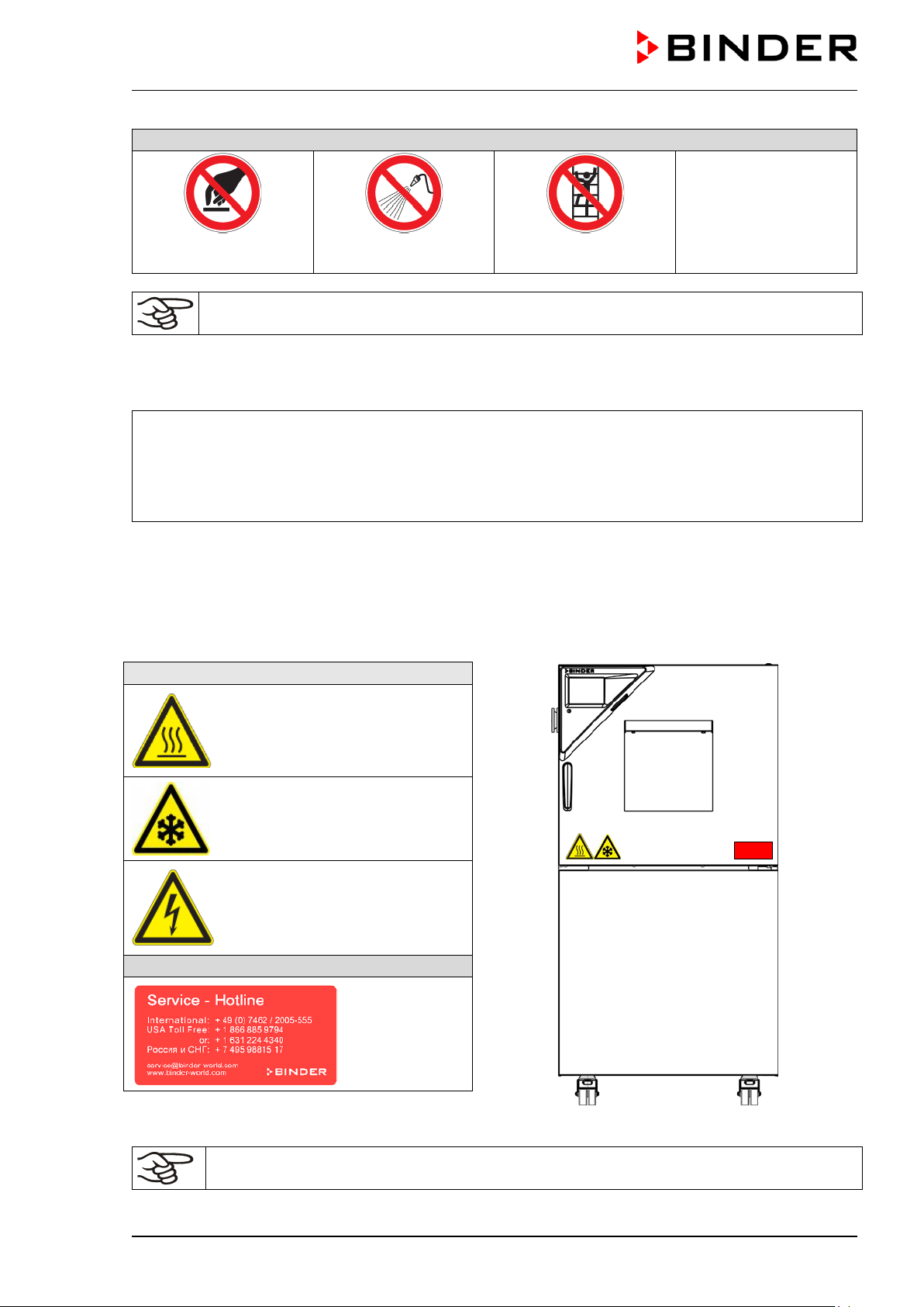
Prohibition signs
water
Pictograms (Warning signs)
Service label
Figure 1: Position of labels on the chamber
Do NOT touch
Do NOT spray with
Information to be observed in order to ensure optimum function of the product.
Do NOT climb
1.2.4 Word message panel structure
Type / cause of hazard.
Possible consequences.
∅ Instruction how to avoid the hazard: prohibition.
Instruction how to avoid the hazard: mandatory action.
Observe all other notes and information not nec essarily emphasized in the same way, in order to avoid
disruptions that could result in direct or indirect injury or property damage.
1.3 Localization / position of safety labels on the chamber
The following labels are located on the chamber:
Hot surface (on chamber door)
Cold surface (on chamber door)
Electrical hazard
(chamber with voltage and frequency changer: on the voltage
and frequency changer)
Keep safety labels complete and legible.
Replace safety labels that are no longer legible. Contact BINDER service for these replacements.
MK / MKT (E5) 03/2019 page 8/158
Page 9
Indications of the type p late (example)
Information
BINDER
Manufacturer: BINDER GmbH
MKT 240
Model
Alternating climate chamber
Device name
Serial No.
00000000000000
Serial no. of the chamber
Built
2018
Year of construction
356 °F
IP protection
20
IP type of protection acc. to EN 60529
Temp. safety device
DIN 12880
Temperature safety device acc. to standard DIN 12880
Class
2.0
Class of temperature safety device
Art. No.
9020-0230
Art. no. of the chamber
Project No.
---
Optional: Special application acc. to project no.
6,50 kW
Nominal power
400 V / 50 Hz
Nominal voltage ± 10% at the indicated power frequency
3 N ~
Current type
11,3 A
Nominal current
Max operating pressure 29 bar
Max operating pressure in the refrigerating system
Stage 1: R 452A – 2,20 kg
Cooling 1st stage: Refrigerant type, filling weight
Stage 2: R 23 – 0,38 kg
Cooling 2nd stage: Refrigerant type, filling weight
Contains fluorinated greenhouse gases
covered by the Kyoto Protocol
Contains fluorinated greenhouse gases covered by the
Kyoto Protocol
Symbol on the type plate
Information
Nominal temp.
180 °C
6,50 kW / 11,3 A
Max. operating pressure 29 bar
356 °F
400 V / 50 Hz
Stage 1: R 452 A – 2,20 kg
IP protection
20
Stage 2: R 23 - 0,38 kg
Safety device
DIN 12880
3 N ~
Contains fluorinated greenhouse gases
Class
2.0 covered by the Kyoto Protocol
Art. No.
9020-0230
Project No.
Built
2018
Alternating climate chamber
BINDER GmbH
www.binder-world.com
MKT 240
Serial No. 00000000000000
1.4 Type plate
The type plate sticks to the left side of the chamber, bottom right-hand, above the refrigerating module.
Im Mittleren Ösch 5
78532 Tuttlingen / Germany
E5
Figure 2: Type plate (example of MKT 240 regular chamber)
Made in Germany
Nominal temperature
180 °C
Nominal temperature
CE conformity marking
Electrical and electronic equipment manufactured / placed on the
market in the EU after 13 August 2005 and to be disposed of in
separate collection according to Directive 2012/19/EU on waste
electrical and electronic equipment (WEEE).
MK / MKT (E5) 03/2019 page 9/158
Page 10
Symbol on the type plate
Information
CAUTION
GS mark of conformity of the “Deutsche Gesetzliche Unfallversicherung e.V. (DGUV), Prüf- und Zertifizierungsstelle Nahrungsmittel
und Verpackung im DGUV Test“ (German Social Accident Insurance (DGUV), Testing and Certification Body for Foodstuffs and
Packaging Industry in DGUV Test). (Not valid for MKF056-240V)
The chamber is certified according to Customs Union Technical
Regulation (CU TR) for the Eurasian Economic Union (Russia, Belarus, Armenia, Kazakhstan Kyrgyzstan).
1.5 General safety instructions on installing and operating the chamber
With regar d to operating the chamber and to the installation location, please observe the DGUV guidelines
213-850 on safe working in laboratories ( f or merly BGI/GUV-I 850-0, BGR/GUV-R 120 or ZH 1/119, issued
by the employers’ liability insurance association) (for Germany).
BINDER GmbH is only responsible for the safety features of the chamber provided skilled electricians or
qualified personnel authorized by BINDER perform all maintenance and repair , and if components relating
to chamber safety are replaced in the event of failure with original spare parts.
To operate the chamber, use only original BINDER accessories or access ories from thir d-party suppliers
authorized by BINDER. The user is responsible for any risk caused by using unauthorized accessories.
Danger of overheating.
Damage to the chamber.
∅ Do NOT install the chamber in unventilated recesses.
Ensure sufficient ventilation for dispersal of the heat.
Do not operate the chamber in hazardous locations.
DANGER
Explosion hazard.
Danger of death.
∅ Do NOT operate the chamber in potentially explosive areas.
∅ KEEP explosive dust or air-solvent mixtures AWAY from the chamber.
The chamber does not dispose of any measures of explosion protection.
DANGER
MK / MKT (E5) 03/2019 page 10/158
Explosion hazard.
Danger of death.
∅ Do NOT introduce any substance into the alternating climate chamber which is combus-
tible or explosive at working temperature.
∅ NO explosive dust or air-solvent mixture in the inner chamber.
Page 11
Any solvent contained in the charging material must not be explosive or inflamm able. I.e., irrespective of
the solvent concentration in the steam room, NO explosive m ixture with air must form. The tem perature
inside the chamber mus t lie below the flash point or below the sublimation point of the charging m aterial.
Familiarize yourself with the physical and chemical properties of the charging m aterial, as well as the contained moisture constituent and its behavior with the addition of heat energy.
Familiarize yourself with any potential health risks caused by the charging material, the contained moisture
constituent or by reaction products that may arise during the temperature process. Take adequate
measures to exclude such risks prior to putting the chamber into operation.
DANGER
Electrical hazard.
Danger of death.
∅ The chamber must NOT become wet during operation or maintenance.
The chambers were produced in accordance with VDE regulations and were routinely tested in accordance to VDE 0411-1 (IEC 61010-1).
CAUTION
The inner chamber, the door window and the access ports will become hot during
operation.
Danger of burning.
∅ Do NOT touch the inner surfaces, the door window, the front panel around the inner
chamber, the access ports, or the charging material during operation.
WARNING
Stability hazard.
Danger of injury.
Damage to the chamber and the charging material.
Housing cover breakaway.
∅ Do NOT climb on the lower housing cover.
∅ Do NOT load the lower housing cover with heavy objects while the chamber door is
open.
MK / MKT (E5) 03/2019 page 11/158
Page 12
1.6 Intended use
Alternating climate chambers MK / MKT are suitable for temperature treatment of solid or pulverized
charging material, as well as bulk material, using the supply of heat or cold. T he chambers can be used
for drying processes, but they are particularly suitable for all tasks that occur in materials testing and aging
tests.
The chambers ar e suitable for harmless m aterials. A m ixture of any component of the charging m aterial
with air must NO T be explosive. The operating tem perature must lie below the flash point or below the
sublimation point of the char ging material. Any component of the charging m aterial must NOT be able to
release toxic gases.
Other applications are not approved.
Do NOT use the cham ber for drying purpose, especially if greater quantities of steam leading to condensation will be set free.
The chambers are not classified as medical devices as defined by the Medical Device Directive
93/42/EEC.
Due to the special demands of the Medical Device Directive (MDD), these ovens are not qualified for sterilization of medical devices as defined by the directive 93/42/EWG.
Following the instructions in this operating manual and conducting regular maintenance work
(chap. 21) are part of the intended use.
The chambers do not dispose of any measures of explosion protection.
DANGER
Explosion or implosio n h azard.
Danger of poisoning.
Danger of death.
∅ Do NOT introduce any substance com bustible or explosive at working tem perature into
the chamber, in particular no energy sources such as batteries or lithium-ion batteries
∅ NO explosive dust or air-solvent mixture in the inner chamber.
∅ Do NOT introduce any substance which could lead to release of toxic gases.
The charging material shall not contain any corrosive ingredients that may damage the machine components made of stainless steel, aluminum, and copper. Such ingredients include in
particular acids and halides. Any corrosive damage caused by such ingredients is excluded
from liability by BINDER GmbH.
In case of foreseeable use of the chamber there is no risk for the user through the integration of the
chamber into systems or by special environmental or operating conditions in the sense of EN 610101:2010. For this, the intended use of the chamber and all its connections must be observed.
MK / MKT (E5) 03/2019 page 12/158
Page 13

1.7 Operating instructions
Depending on the application and location of the chamber, the operator of the alternating climate chamber
must provide the relevant information for safe operation of the chamber in a set of operating instructions.
Keep these operating instructions with the chamber at all times in a place where they are
clearly visible. They must be comprehensible and written in the language of the employees.
1.8 Measures to prevent accidents
The operator of the cham ber must observe the following rule: “Betreiben von Arbeitsmitteln. Betreiben von
Kälteanlagen, Wärm epumpen und Kühleinrichtungen“ (Operation of work equipment. Operation of refr igeration systems, heat pumps and refrigeration equipment) (GUV-R 500 chap. 2.35) (for Germany).
The manufacturer took the following measures to prevent ignition and explosions:
• Indications on the type plate
See operating manual chap. 1.4.
• Operating manual
An operating manual is available for each chamber.
• Overtemperature monitoring
The chamber is equipped with a temperature display, which can be read from outs.
The chamber is equipped with an additional saf et y controller (tem per ature s af ety device c lass 2 acc . to
DIN 12880:2007). Visual and audible (buzzer) signals indicate temperature exceeding.
• Safety, measurement, a n d control equipment
The safety, measuring, and control equipment is easily accessible.
• Electrostatic charge
The interior parts are grounded.
• Non-ionizing radiation
Non-ionizing radiation is not intentionally produced, but released only for technical reasons by electrical
equipment (e.g. electric m otors, power c ables, solenoids) . The m ac hine has no perm anent magnets . If
persons with active implants (e.g. pacem akers, defibrillators) keep a safe distance (distanc e of field
source to implant) of 30 cm, an influence of these implants can be excluded with high probability.
• Protection against touchable surfaces
Tested according to EN ISO 13732-1:2008.
• Floors
See operating manual chap. 3.4 for correct installation
• Cleaning
See operating manual chap. 21.2.
• Examinations
The chamber has been inspected by the “Deutsche Gesetzliche Unfallversicherung e.V. (DGUV)
(German Social Accident Insurance (DGUV)” (German Social Accident Insurance (DGUV), Testing
and Certification Body for Foodstuffs and Packaging Industry in DGUV Test) and bears the GS mark.
(Not valid for MK056-240V)
MK / MKT (E5) 03/2019 page 13/158
Page 14

2. Chamber description
The alternating climate cham ber MK / MKT is a s pecially developed precision cooling/warming cabinet f or
the domain of industr ial mat erial testing and environm ent sim ulation, with an unrivalled capacity, which far
exceeds the capabilities of norm al test cabinets, providing the ideal facilities for solving all the problems
which occur during material as well as ageing and stress tests.
The chambers ar e equipped with a multifunctional microproces sor display controller for temperature with
a digital display accurate to one-tenth of a degree. W ith its com prehensive progr am contr ol functions, the
display program controller MB2 perm its the high precision perf ormance of temperatur e cycles with rapid
heating up and cooling down phases.
The patented APT.line™ preheating cham ber and air conduction technology guarantees excellent spatial
temperature values for the total working area. T he chamber is equipped with a powerful refrigerating system permitting rapid cooling-down speeds. In addition, it provides almost unlim ited poss ibilities f or adapt ation to individual customer requirements based upon extensive programming options.
The high-quality housing insulation guarantees both a low noise mode of operation and a consistently low
housing temperature. T he inner chamber, the pre-heating cham ber and the interior side of the doors are
all made of stainless steel V2A (Germ an material no. 1.4301, US equivalent AISI 304). When operating
the chamber at temper atures above 150 °C / 302°F, the impact of the oxygen in the air may cause discoloration of the metallic surfac es (yellowish-brown or blue) by natural oxidation processes. These colorations are harmless and will in no way impair the function or quality of the chamber. The hous ing is RAL
7035 powder-coated. All corners and edges are also completely coated.
The efficient program controller is equipped with a m ultitude of operat ing functions , in addition to recorder
and alarm functions. Pr ogramming of test cycles is easily accomplished via the modern touchscreen display controller MB2 and is also pos sible directly with a computer via Intranet in connection with the APTCOM™ 4 Multi Management Software (option, chap. 20.1) . The chamber comes regularly equipped with
an Ethernet serial interface for com puter communication. In addition, the BINDER APT-COM™ 4 Multi
Management Software (option) perm its networking up to 100 chambers and connecting them to a PC for
controlling and programming, as well as rec or ding and repres enting temperature data. For further options,
see chap. 24.6.
The chambers
brakes.
MK: You can operate the chamber in a temperature range from -40 °C / -40 °F up to +180 ºC / 356 °F.
MKT: You can operate the chamber in a temperature range from -70 °C / -94 °F up to +180 ºC / 356 °F.
are equipped with f our castors. Both front castors can be easily locked via the attached
MK / MKT (E5) 03/2019 page 14/158
Page 15
(A)
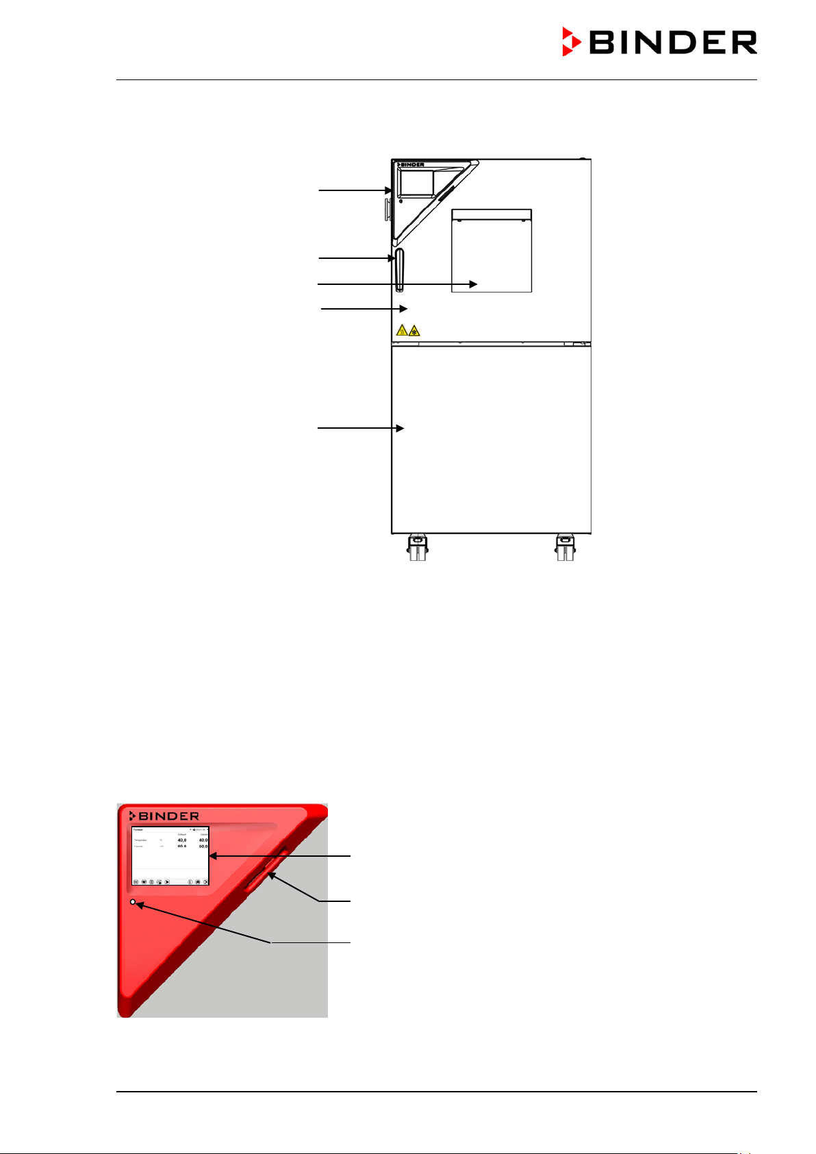
2.1 Chamber overview
(B)
(C)
(D)
(E)
Figure 3: Alternating climate chamber (example: MK 56)
(A) Instrument panel
(B) Door handle
(C) Inspection window
(D) Chamber door
(E) Refrigerating machine, maintenance access flaps
2.2 Instrument panel
5,7" controller display with touchscreen
USB interface
Pilot lamp
Figure 4: Triangle instrument panel with program controller MB2 and USB interface
MK / MKT (E5) 03/2019 page 15/158
Page 16
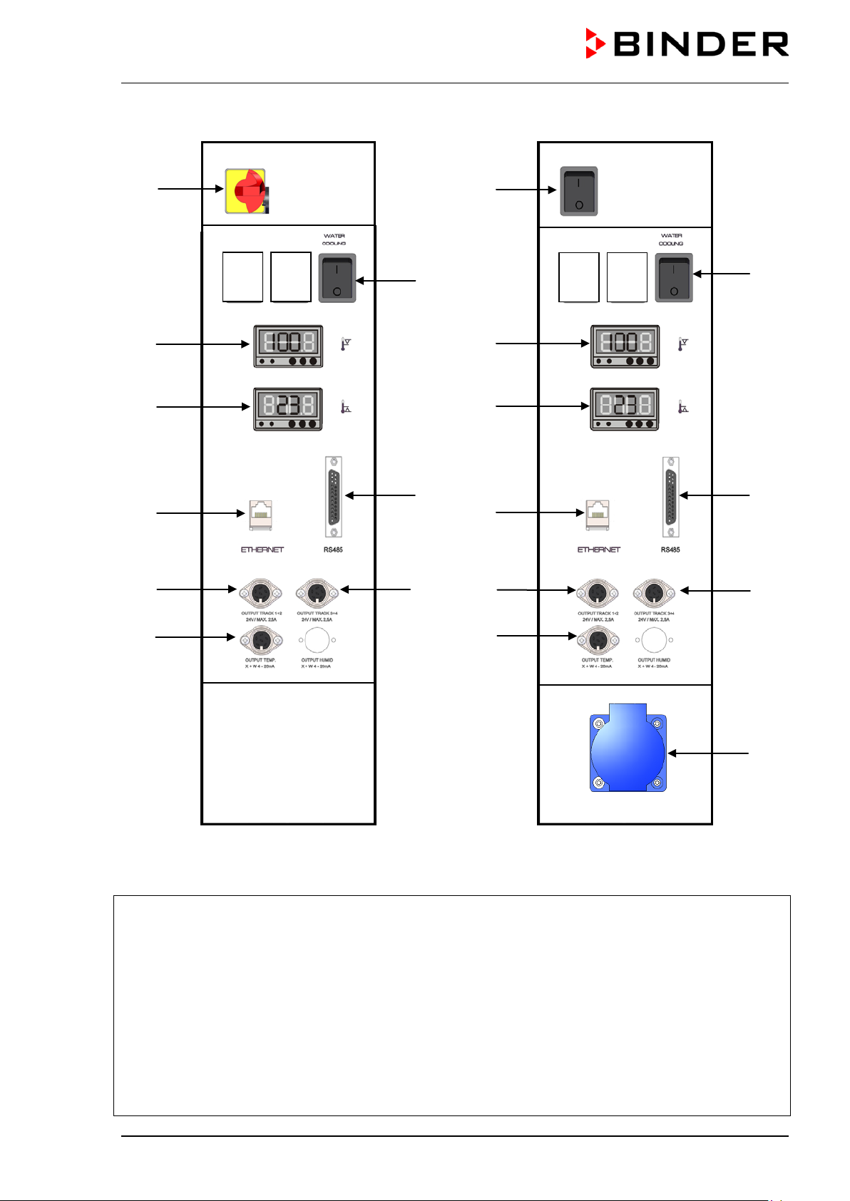
2.3 Lateral control panel
(1)
(4a)
(4b)
(5)
(7)
(9)
(3)
(5a)
(8)
(1)
(4a)
(4b)
(5)
(7)
(9)
(3)
(5a)
(8)
(11)
MK 56 MK 115 / 240 / 720
Figure 5: Lateral control panel at the right side of the refrigerating machine, with options
(1) Main power switch On/Off
(2) not used
(3) Switch for water cooling (option for MK 56, for
other chambers available via BINDER Individual
Customized Solutions)
(4) Temperature safety device class 2 for over and
under temperature (option):
Entry displays for upper (4a) and lower (4b)
temperature limit
(5) Ethernet interface for computer communication
(5a) RS485 interface for computer communi-
cation (option)
(6) not used
(7) 2 zero-voltage switching outputs via op-
eration lines (MKT, option with MK))
(8) 2 zero-voltage switching outputs via op-
eration lines (MKT, option with MK)
(9) Analog output for temperature (option)
(10) not used
Socket 230 V AC, max. 500 W (MK/MKT
(11)
115, 240, 720)
MK / MKT (E5) 03/2019 page 16/158
Page 17
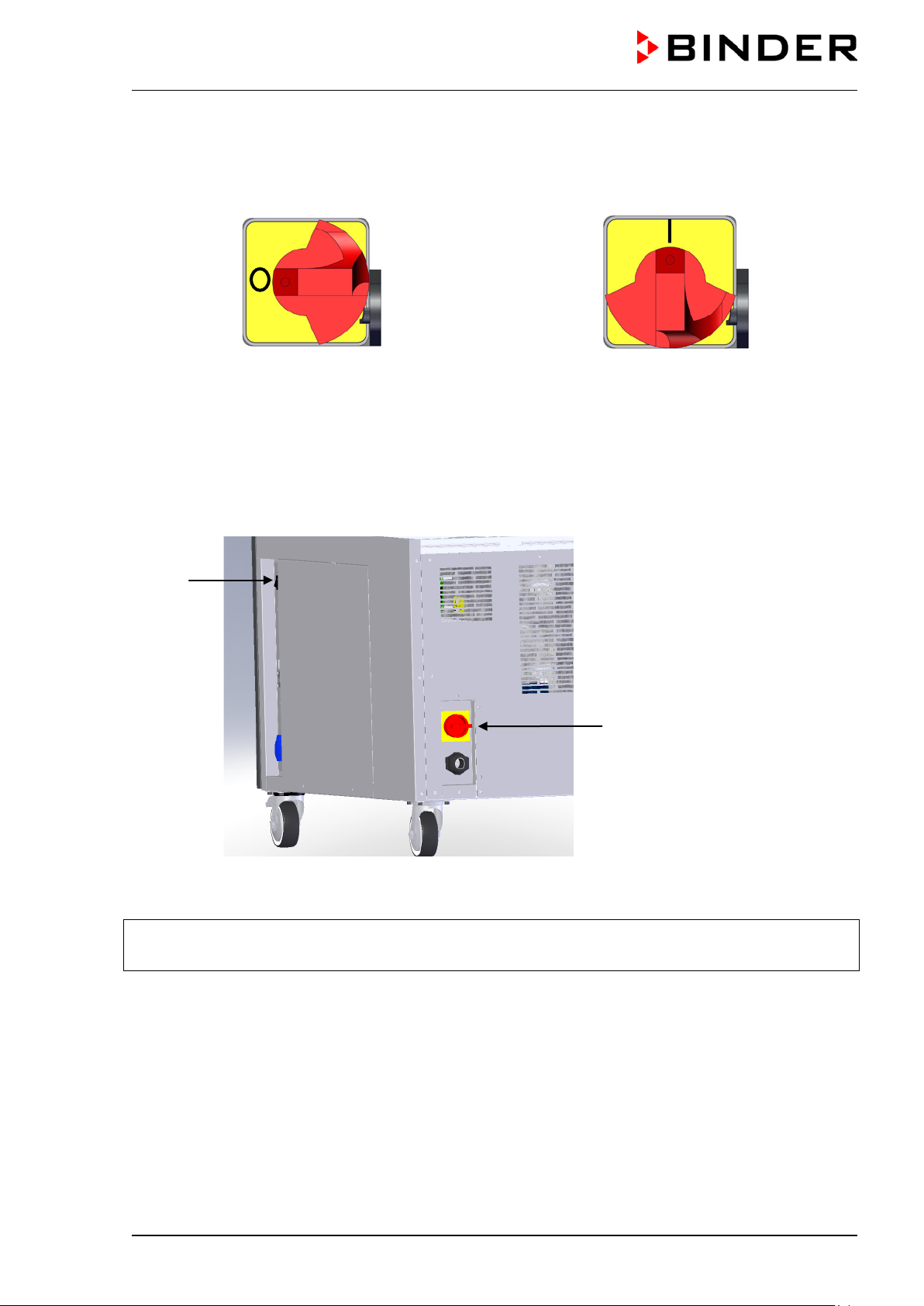
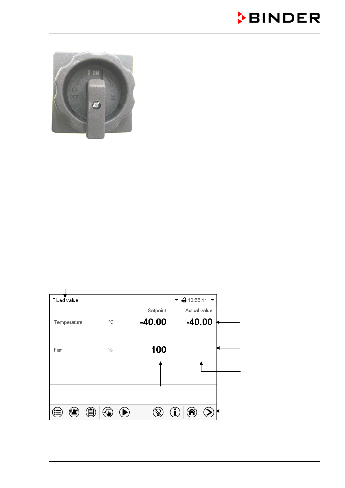
2.4 Main power switch (MK 56)
This switch allows completely switching off the chamber (de-energized condition).
Off On
Figure 6: Main power switch (1) in the MK 56 lateral control panel
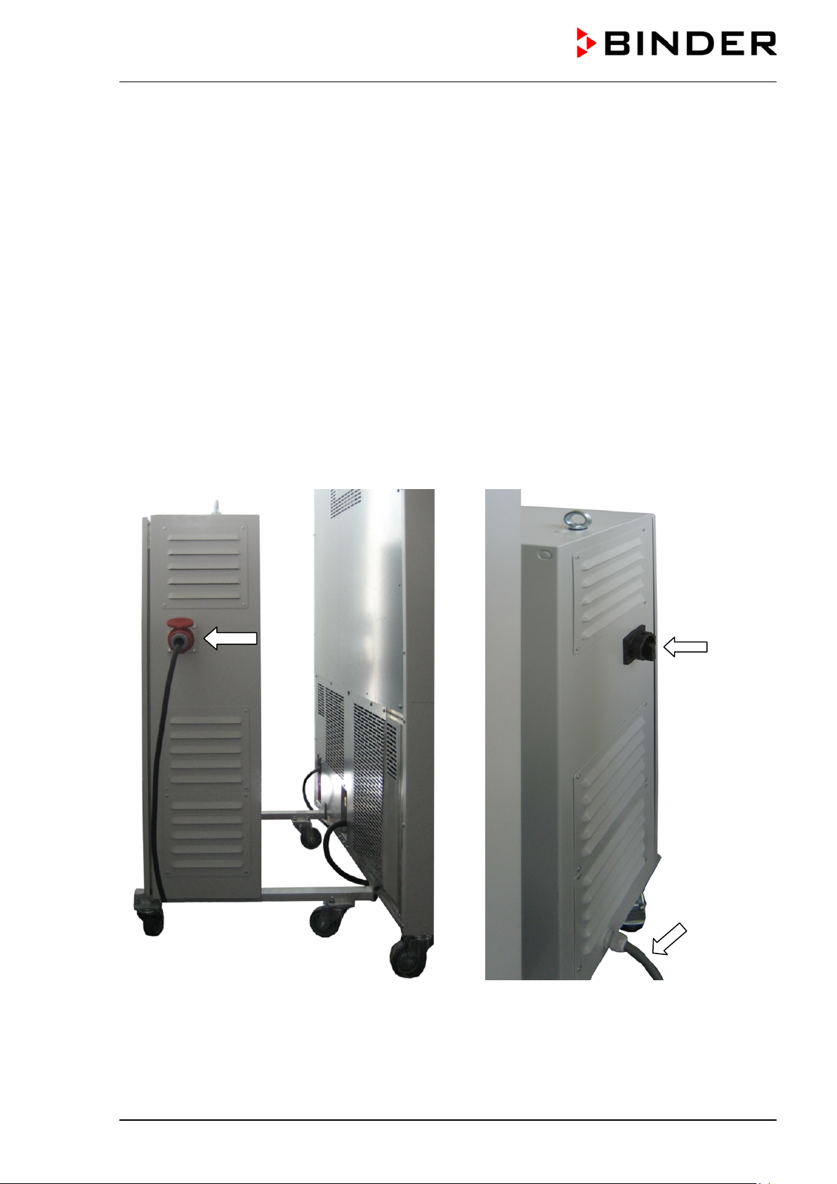
2.5 Rear power switch (MK / MKT 115, 240, 720)
This switch allows completely switching off the chamber (de-energized condition).
(1)
Figure 7: Rear view MK/MKT 115, 240, 720
(1) Main power switch On / Off
(12) Rear power switch
(12)
MK / MKT (E5) 03/2019 page 17/158
Page 18
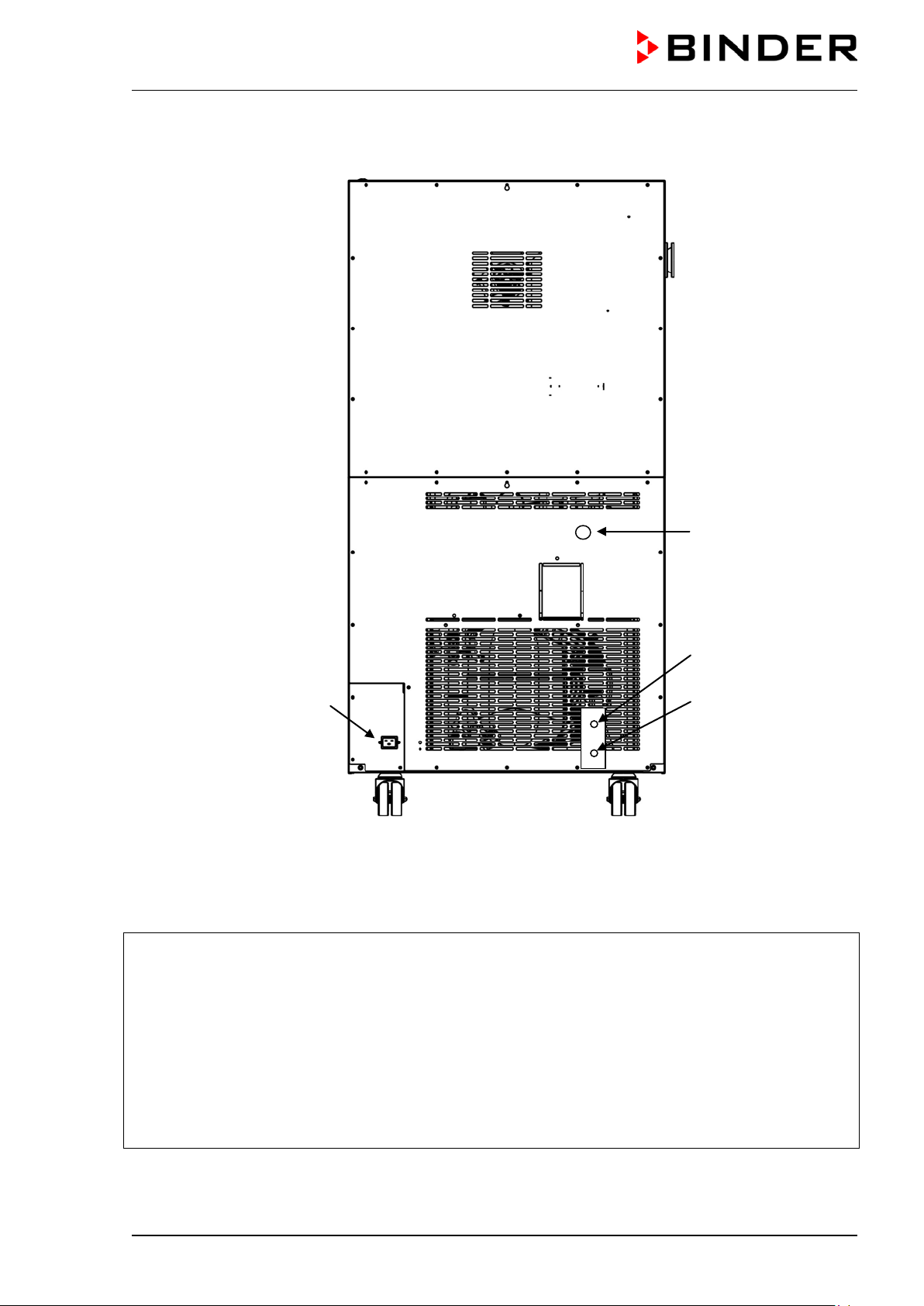
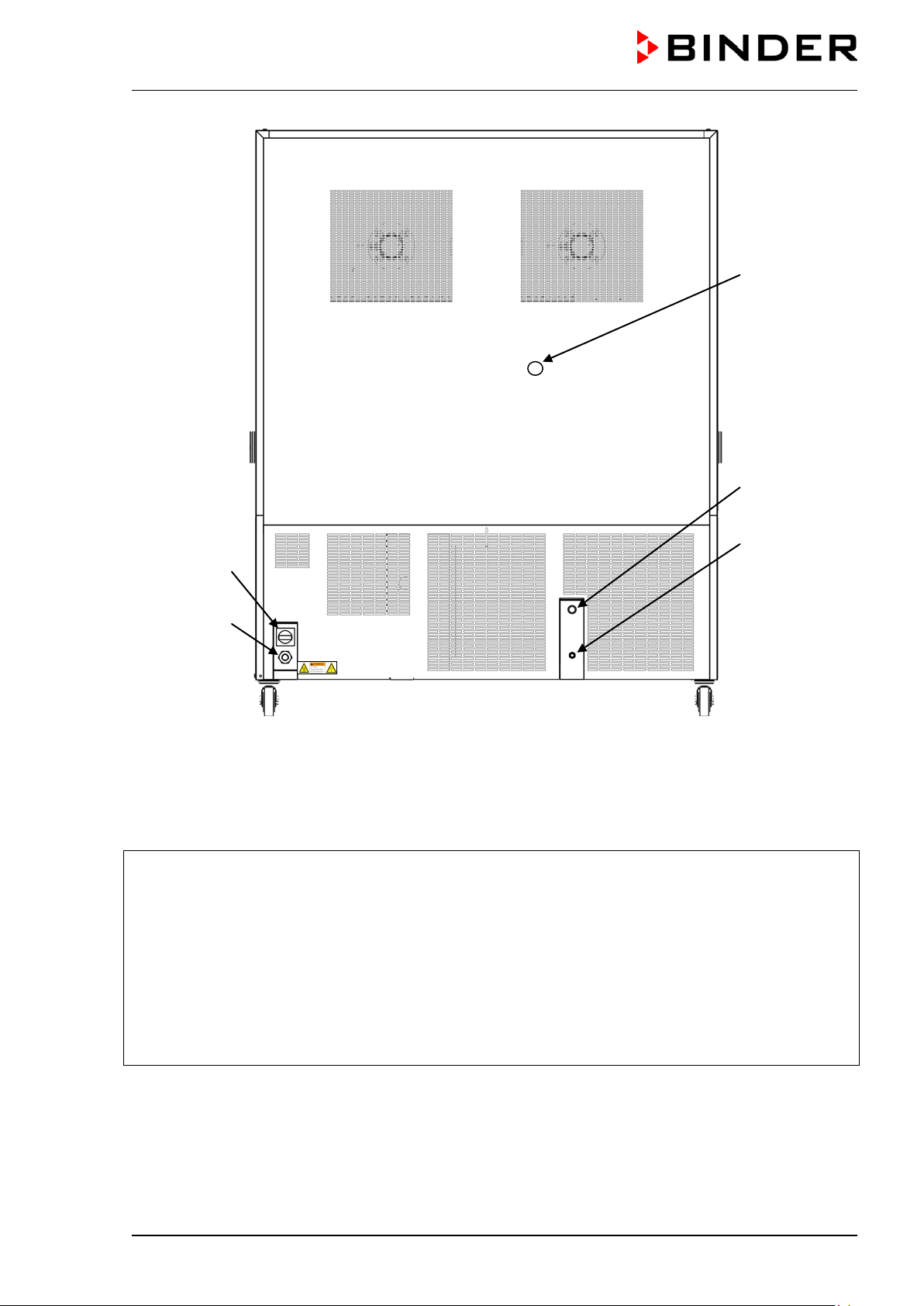
2.6 Rear chamber view
(19)
(20)
(16)
(17)
Figure 8: MK 56 rear chamber view with options water cooling and compressed air connection
(12), (13), (14), (15) not used
(16) Connection “OUT” for cooling water outlet with screw thread ¾’’ for hos e ½“, with union nut (option
water cooling)
(17) Connection “IN” for cooling water inlet with screw thread ¾’’ for hos e ½“, with union nut (option
water cooling)
(18) not used
(19) IEC connector plug
(20) Compressed air connection ( option): Coupling connector to connect compressed air or the c om-
pressed air dryer (option)
MK / MKT (E5) 03/2019 page 18/158
Page 19
Connection “IN” for cooling water inlet with
(12)
(20)
(16)
(17)
(19)
Figure 9: MK/MKT 115, 240, 720 rear chamber view
with options water cooling and compressed air connection (example: MK 720)
(12) Rear power switch
(13), (14), (15) not used
(16) Connection “OUT” for cooling water outlet with
screw thread ¾’’ for hose ½“, with union nut
(water cooling option, available via BINDER
(18) not used
(19) Power connection
(20) Compressed air connection (option): Cou-
pling connector to connect compressed air
or the compressed air dryer (option)
Individual Customized Solutions)
(17)
screw thread ¾’’ for hose ½“, with union nut
(water cooling option, available via BINDER
Individual Customized Solutions)
MK / MKT (E5) 03/2019 page 19/158
Page 20
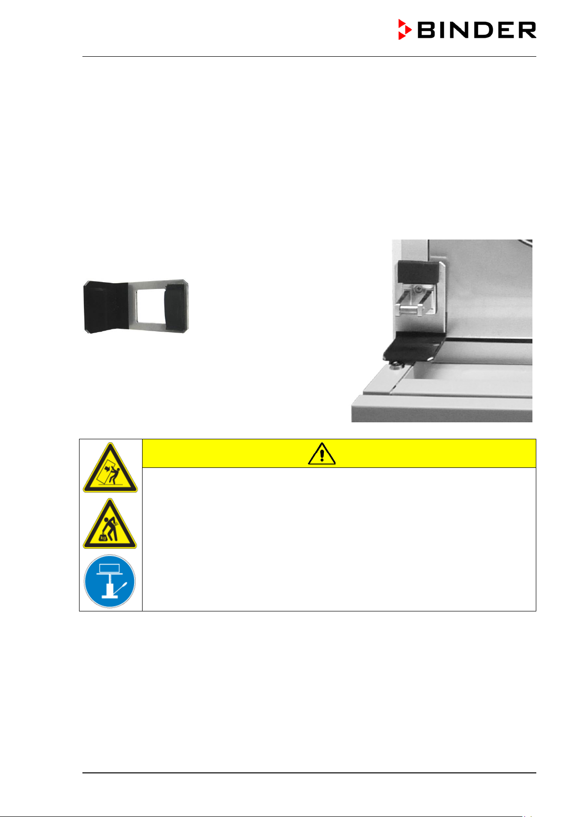
Remove the upholstered transport piece (L-type profile)
3. Completeness of delivery, transportation, storage, and installation
3.1 Unpacking, and checking equipment and completeness of delivery
After unpacking, please check the chamber and its optional accessories, if any, based on the delivery
receipt f or completeness and for transportation dam age. Inform the carrier immediately if transportation
damage has occurred.
The final tests of the manufactur er may cause traces of the shelves on the inner surf aces. This has no
impact on the function and performance of the chamber.
Please remove any transportation protection devices and adhesives in/on the chamber and on the doors
and take out the operating manuals and accessory equipment.
from the lower door locking and keep it for possible later
transportation.
Figure 10:
Door locking with transport piece (state of delivery)
CAUTION
Sliding or tilting of the chamber.
Damage to the chamber.
Risk of injury by lifting heavy loads.
∅ Do NOT lift or transport the chamber using the door, the handle or the lower housing.
∅ Do NOT lift the chamber by hand.
Keep the chamber in upright position.
Lift chambers from the pallet using technical devices (fork lifter). Set the fork lifter only
from the rear in the middle of the chamber. Make sure to place all the lateral supports
of the chamber on the forks.
If you need to return the chamber, please use the original packing and obser ve the guidelines for safe
lifting and transportation (chap. 3.2).
For disposal of the transport packing, see chap. 22.1.
Note on second-hand chambers (Ex-Demo-Units):
Second-hand chambers are chambers that were used f or a short time for tests or exhibitions. T hey are
thoroughly tested before resale. BINDER ensures that the chamber is technically sound and will work
flawlessly.
Second-hand chambers are marked with a stick er on the chamber door. Please remove the sticker before
commissioning the chamber.
MK / MKT (E5) 03/2019 page 20/158
Page 21
3.2 Guidelines for safe lifting and transportation
The front castors of the c hamber can be bloc k ed by brakes. Please move the chambers with castors only
when empty and on an even surface, otherwise the castors may be damaged. Mount the upholstered steel
L-type profile at the lower door locking. After operation please observe the guidelines for tem porarily decommissioning the chamber (chap. 22.2).
CAUTION
Sliding or tilting of the chamber.
Damage to the chamber.
Risk of injury by lifting heavy loads.
∅ Do NOT lift or transport the chamber using the door, the handle or at the lower hous-
ing.
∅ Do NOT lift the chamber by hand.
Transport the chamber only in its original packaging.
Secure the alternating climate chamber with transport straps for transport.
Keep the chamber in upright position.
Place the chamber using technical devices (fork lifter) on the transport pallet. Set the
fork lifter only from the rear in the middle of the chamber. Make sure to place all the
lateral supports of the chamber on the forks.
Transport the chamber with the original transport pallet. Set the fork lifter ONLY to the
pallet. Without the pallet the chamber is in imminent danger of overturning.
• Permissible ambient temperature range during transport: -10 °C / 14 °F to +60 °C / 140 °F.
You can order transport packing and pallets for moving or shipping purposes from BINDER service.
3.3 Storage
Intermediate storage of the chamber is possible in a closed and dry room. Observe the guidelines for
temporary decommissioning (chap. 22.2).
• Permissible ambient temperature range during storage: -10 °C / 14 °F to +60 °C / 140 °F.
• Permissible ambient humidity: max. 70 % r.h., non-condensing
When af ter storage in a cold location you transfer the chamber to its warm er installation site, condensation may form. Before star t-up, wait at least two hours until the chamber has attained ambient temperature
and is completely dry and the oil in the compressors has warmed up.
In case of a prolonged tempor al decommissioning: Leave the chamber door open or rem ove the access
port plugs.
3.4 Location of installation and ambient conditions
Set up the chamber on a flat, even and non-flammable surface, free from vibration, and in a wellventilated, dry location and align it using a spirit level. The site of installation must be capable of s upporting the chamber’s weight (see technical data, chap. 24.4). T he chambers are designed f or setting up inside a building (indoor use).
When af ter storage in a cold location you transfer the chamber to its warm er installation site, condensation may form. Before star t-up, wait at least two hours until the chamber has attained ambient temperature
and is completely dry and the oil in the compressors has warmed up.
MK / MKT (E5) 03/2019 page 21/158
Page 22
CAUTION
Danger of overheating.
Damage to the chamber.
∅ Do NOT set up chambers in non-ventilated recesses.
Ensure sufficient ventilation for dispersal of the heat.
• Permiss ible ambient temperature r ange during operation: +18 °C / 64.4 °F to +32 °C / 89.6 °F. At ele-
vated ambient temperature values, fluctuations in temperature can occur.
The ambient temperature should not be substantially higher than the indicated ambient temperature of +25 °C / 77 °F to which the specified technical data relate. For other ambient conditions, deviations from the indicated data are possible.
• Permissible ambient humidity: 70 % r.h. max., non-condensing.
When operating the c hamber at temperatur e set-points below am bient tem perature, high am bient hum idi-
ty may lead to condensation on the chamber.
• Installation height: max. 2000 m / 6562 ft. above sea level.
Minimum distances:
• Distance between each cham ber when placing several chambers of the sam e size side by side: 250
mm / 9.84 in
• Lateral wall distance: 200 mm / 7.87 in
• Wall distance rear: 300 mm / 11.81 in
• Chambers with optional water cooling (without options compressed air dryer and / or voltage and fre-
quency changer): Wall distance rear 100 mm / 3.94 in.
• Chambers with optional compr essed air dr yer: Wall distance rear approx. 1 m / 3.28 ft so that it is pos-
sible to read the status display of the compressed air dryer on the chamber rear.
• Chambers with voltage and frequency changer: rear wall distance of the alternating clim ate chamber
approx. 1 m / 3.28 ft to set up the voltage and frequency changer
• To completely separate the chamber from the power supply, you must disconnect the power plug. In-
stall the chamber in a way that the power plug is easily accessible and can be easily pulled in case of
danger.
• Spacing above the chamber: 100 mm / 3.94 in
CAUTION
Danger by stacking.
Damage to the chambers.
∅ Do NOT place the chambers on top of each other.
With an increas ed amount of dust in the ambient air, clean the condens er fan several times a year. We
recommend c heck ing the fan gr id (behind the left m aintenance ac cess flap) every week. In case of visible
dirt accumulation, disconnect the chamber and clean the fan grid by suction.
Avoid any conductive dust in the ambiance according to the chamber layout complying with pollution degree 2 (IEC 61010-1).
MK / MKT (E5) 03/2019 page 22/158
Page 23
Do not install or operate the alternating climate chamber in potentially explosive areas.
DANGER
Explosion hazard.
Danger of death.
∅ Do NOT operate the chamber in potentially explosive areas.
∅ KEEP explosive dust or air-solvent mixtures AWAY from the vicinity of the chamber.
4. Installation and connections
4.1 Connection of cooling water outlet for water cooling (option for MK 56)
An enclosure inside the chamber contains the connection kit for the cooling water inlet and outlet.
• Fasten the cooling hose to the connection “OUT” (16) on the rear of the chamber (screw thread ¾’’).
• You can use a part of the supplied tap water hose as a drainage hos e. In case another hose is us ed, it
has to be permanently resistant against max. 50 °C / 122 °F.
• Protect both ends of the dr ainage hose with two of the four supplied hose clamps. Before turning on
the chamber, check the connection for leaks.
4.2 Connection of cooling water inlet for water cooling (option for MK 56)
Connect the cooling water outlet before connecting the cooling water inlet.
Type of suitable water quality:
• Water intake temperature: max. 10 °C / 50 °F.
• pH value 4-7
• connection pressure: 4 to 10 bar
BINDER GmbH is NOT responsible for the water quality at the user’s site.
Any problems and malfunctions that might arise following use of water of deviating quality is
excluded from liability by BINDER GmbH.
The warranty becomes void in the event of use of water of deviating quality.
Connection:
An enclosure inside the chamber contains the connection kit for the cooling water inlet and outlet.
• Fasten the cooling water hose to the connection “IN” (17) on the rear of the chamber (sc rew thread
¾’’).
• Install the water s upply connection using either the enclosed water hose or another pressur e-resistant
one. To accomplish this, remove the cover of the freshwater connection “IN” (17) on the rear of the
chamber.
• The nom inal diameter of the supplied water hose is ½ ", the length is 3m . The hose can be halved for
the inlet and the outlet.
• The m axim um hose length with nom inal width ½ " is 5m. If a longer hose is necessary, a larger diame-
ter hose must be used.
MK / MKT (E5) 03/2019 page 23/158
Page 24
• Protect both ends of the hose with two of the f our supplied hose clamps . Before turning on the cham-
ber, check the connection for leaks.
Water consumption:
The average water demand is not helpful f or the design of the water supply line, since the supply line must
provide sufficient dimensions for peak loads.
Peak values occur briefly (<5 min) when temperature rapidly decreases from + 180 ° C to a much lower
value. Also the activation of the condensation protection leads to high water consumption.
Max. water flow rate (peak value):
• MK 56: approx. 0,6 m³/h
4.3 Installation of the voltage and frequency changer
(chambers with voltage and freque ncy changer)
The voltage and frequency changer is supplied packed separately together with the chamber.
CAUTION
Sliding or tilting of the voltage and frequency chan g er.
Damage to the voltage and freq u ency changer.
Risk of injury by lifting heavy loads.
∅ Do NOT lift the voltage and frequency changer by hand.
Lift the voltage and frequency changer from the pallet using technical devices (fork
lifter). Set the fork lifter only from the rear in the middle of the chamber.
Alternatively, the voltage and frequency changer can also be lifted at the eyelets on the
top by means of a lifting crane or fork lifter
MK / MKT (E5) 03/2019 page 24/158
Page 25
(a)
(b)
(a)
(b)
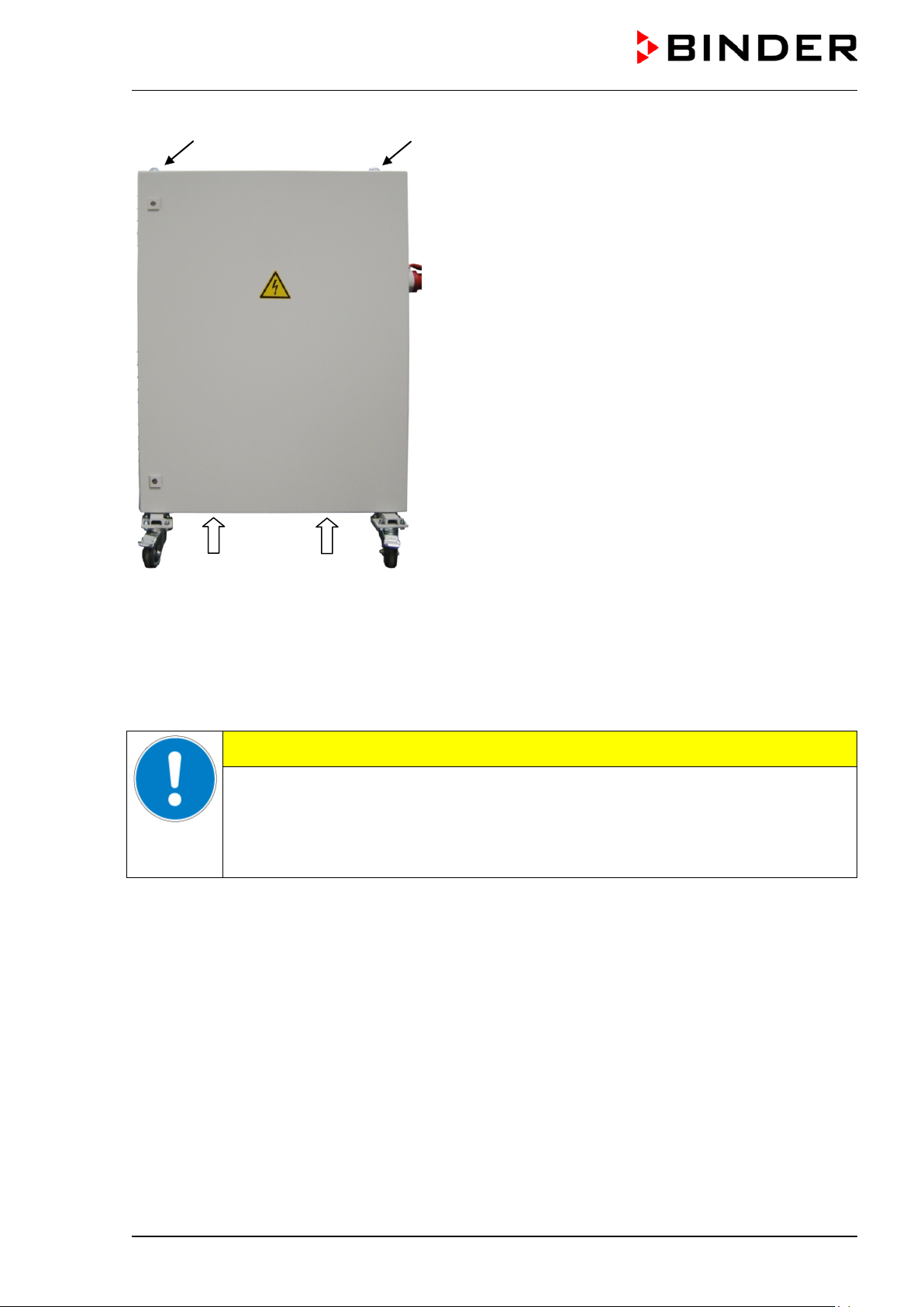
(a) Eyelets for lifting with a lifting crane or fork lifter
(b) Positions for a fork lifter
Figure 11: Positioning of aids for lifting the voltage
and frequency changer
For the installation of the voltage and frequency changer behind the c hamber, provide a rear wall distance
of the chamber of approx. 1 m / 3.3 ft.
If possible, fix the voltage and frequency changer at the chamber . For this purpose, an Allen k ey size 4 is
required. Connect the slots at the end of the c has sis with two M6 screws to the thr eads provided below on
the rear panel of the chamber (see Figure 12).
CAUTION
Danger of overheating.
Damage to the voltage and freq u ency changer.
∅ Do NOT install the voltage and frequency changer in unventilated recesses.
Ensure sufficient ventilation for dispersal of the heat.
The voltage and frequency changer is equipped with f our castors. The rear castors can be easily locked
via the attached brakes
MK / MKT (E5) 03/2019 page 25/158
Page 26
indicated power frequency
MK 115
MK 720
CEE plug 5-poles
32 Amp
25 Amp
3 x internal
4.4 Electrical connection
4.4.1 Information on connecting the alternating climate chamber
The chambers are supplied ready for connection.
MK 56: The chamber s come with an IEC connector plug and are equipped with 1 internal overload re-
lease against excess-current.
MK/MKT 115,240,720: The cham bers come with a fix ed power connection cable of at least 1800 mm /
70.87 in in length. They are equipped with three internal overload releases against excess-current.
Model Power plug
MK 56
(230V)
MK 56
(240V)
MKT 115
MK 240
MKT 240
MKT 720
• The dom estic socket must also pr ovide a protective conductor. Make sure that the connection of the
protective conductor of the dom estic installations to the cham ber ’s protective conductor m eets the latest technology. The protective conductors of the socket and plug must be compatible!
• Prior to connection and start -up, check the power supply voltage. Compare the values to the specif ied
data located on the chamber’s type plate (left chamber side, bottom right-hand, see chap. 1.4)
• W hen c onnecting, please obs erve the regulations spec ified by the local electricity supply company and
as well as the VDE directives (for Germany). We recommend the use of a residual current circuit
breaker.
IEC connector plug
(grounded plug)
IEC connector plug
(grounded plug)
CEE plug 5-poles
16 Amp
Nominal voltage +/- 10% at the
230 V at 50 Hz 1 N~
240 V at 60 Hz 2~
400 V at 50 Hz 3 N~
400 V at 50 Hz 3 N~
Current type Chamber fuse
16 Amp
internal
16 Amp
internal
16 Amp
3 x internal
• MK 56: Only use original connection cables from BINDER
• Pollution degree (acc. to IEC 61010-1): 2
• Over-voltage category (acc. to IEC 61010-1): II
See also electrical data (chap. 24.4 and 24.5).
MK / MKT (E5) 03/2019 page 26/158
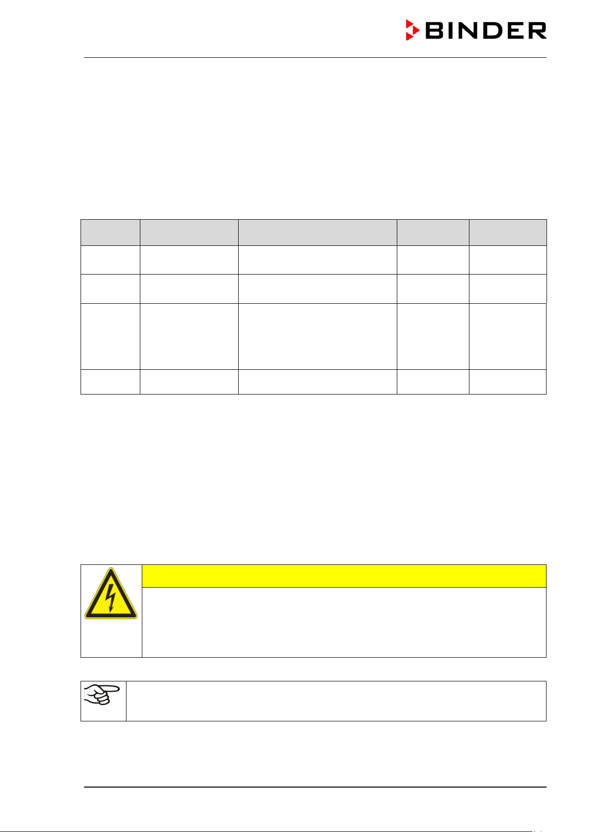
CAUTION
Danger of incorrect po wer supply voltage.
Damage to the equipment.
Check the power supply voltage before connection and start-up.
Compare the power supply voltage with the data indicated on the type plate.
To completely separate the chamber from the power supply, you must disconnect the power
plug. Install the chamber in a way that the power plug is easily accessible and can be easily
pulled in case of danger.
Page 27
Left side of the voltage and frequency changer
chamber
Right side of the voltage and frequency changer
(H)
(I)
(G)
4.4.2 Connecting the voltage and frequency changer (for chambers equipped with a
voltage and frequency changer)
The voltage and frequency changer is supplied with a fixed power connec tion cable without a plug. It is
protected against excess -current with 3 internal overload releases. The connection is made by the customer.
The socket must provide a protective conductor.
Electrical connection data:
• Input side: 480 V, 60 Hz, 4-wire
• Output side (to the chamber): 400 V, 50 Hz, 5-wire
To establish the electrical connection of the alternating climate chamber with the voltage and frequency
changer, proceed in the following order:
1. Connect the chamber to the connection socket (G) of the voltage and frequency changer
2. Establish the power connection of the voltage and frequency changer using the power cable (I)
3. Turn on the voltage and frequency changer at the power switch (H) (position “ON”)
4. Turn on the chamber with the main power switch (3) in the lateral control panel
with connection socket (G) for the alternating climate
MK / MKT (E5) 03/2019 page 27/158
with power switch (H) and power cable (I)
Figure 12: Voltage and frequency changer, mounted
Page 28
Operating mode
Figure 13: Power switch (H) of the voltage and frequency changer in position “ON”
In position “OFF” the switch can be locked, e.g. with a padlock.
5. Functional overview of the MB2 chamber contr oller
The MB2 cham ber c ontr oller c ontrols the temperature (closed loop control), and the f an s peed (adjustable
only with MK 56) inside the chamber.
You can enter the desired set point values in fixed value operation m ode dir ectly on the display surface or
via the setpoint menu. For program oper ation the controller of fer s program ming week and time program s .
In addition there is a timer program available (stopwatch function).
The controller offers various notifications and alarm mes sages with visual and audible indication and remote alarms via e-mail, an event list (trace file) and the graphical display of the measuring values in the in
der chart recorder view. The MB2 progr am controller per m its programming tem perature c ycles and specifying the fan speed (with MK 56) and special controller f unctions f or each program sect ion. You can enter
values or programs directly at the controller or use the APT-CO M™ 4 Multi Management Software (option) specially developed by BINDER.
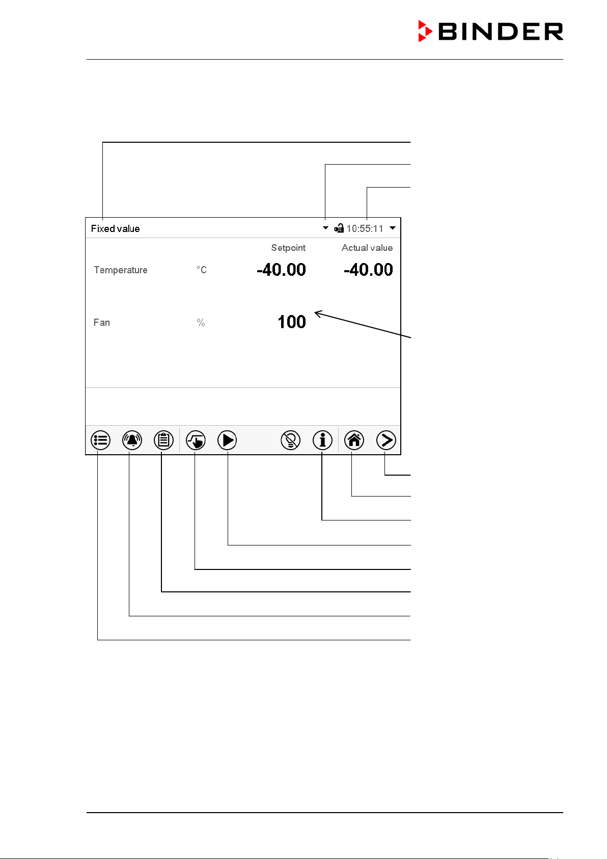
Temperature values
Fan speed value
Actual values
Set-point values
Functional icons
Figure 14: Normal display of the MB2 program controller (sample values with MK 56)
MK / MKT (E5) 03/2019 page 28/158
Page 29
Current operating mode
Date, time, authorization level
5.1 Operating functions in normal display
Text list for information icons
of the logged-in user, memory
Quick setpoint entry
Continue to next screen
Back to Normal display
Information
Program start
Setpoint entry
Event list
Display of active alarms
Access to main menu
Figure 15: Operating functions of the MB2 controller in normal display (sample values with MKF 56)
MK / MKT (E5) 03/2019 page 29/158
Page 30
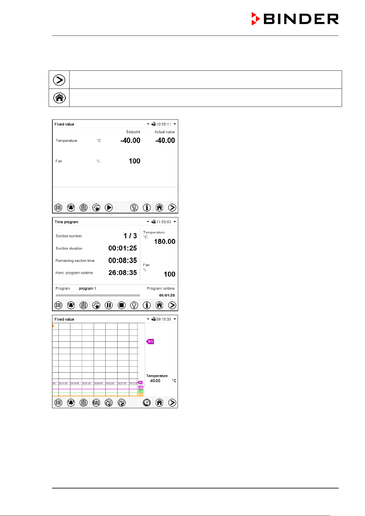
5.2 Display views: Normal display, program display, chart-recorder display
Press the Change view icon to toggle between normal display, program display and chartrecorder display.
Press the Normal display icon to return from program display and chart recorder display back to
Normal display.
Normal display (actual values / setpoint values)
Program display (example: time program)
Chart recorder display
MK / MKT (E5) 03/2019 page 30/158
Page 31

Icon
Signification
Function
Icon
Signification
Function
5.3 Controller icons overview
Navigation icons in Normal display
Main menu
Alarm
Event list
Setpoint setting
Program start
Program pause
Program cancelling
Information
Normal display
Change view
Interior lighting
Access from Normal display to the main menu
Access from Normal display to the list of active alarms
Access from Normal display to the event list
Access from Normal display to the setpoint entry menu: setpoint
entry for Fixed value operation, safety controller settings
Start a previously entered time or week program,
continue a paused time program
Pause a running time program
Cancel a running time or week program
Information on program operation, setpoints, actual values, and
the safety controller
Return from program display or chart recorder display to Normal
display
Toggle between Normal display, program display, and chart re-
corder display
Turn on and off the interior lighting
Functional icons in individual menus
Back
Update
Confirm
Close
Reset alarm
Change keyboard
Edit
Return from each menu to Normal display
Update the event list and alarm messages
Take over the entries and exit the menu / continue menu se-
quence.
Exit the menu / cancel menu sequence. Entries are not taken
over. When terminating a menu sequence, an information window appears, which must be confirmed.
Acknowledge the alarm and mute the buzzer.
Change between uppercase and lower case characters, digits
and special characters
Edit settings of time and week programs
MK / MKT (E5) 03/2019 page 31/158
Page 32

Icon
Signification
Function
Icon
Text information
Condition
Icon
Information
Functional icons in the chart recorder displ ay
Show legend
Hide legend
Switch legend
Show indications
Hide indications
History display
Curve selection
Search
Zoom
Show scroll buttons
Hide scroll buttons
Show legend
Hide legend
Switch between legend pages
Show indications “Door open” (B1), “Anti-condensat.” (B2), “Com-
pressed air” (B3)
Hide indications “Door open” (B1), “Anti-condensat.” (B2), “Com-
pressed air” (B3)
Pause chart recorder and change to history display. Data recording
continues.
Go to “Curve selection” submenu in the history display
Go to “Search” submenu in the history display to select the required
instant
Go to “Zoom” submenu in the history display to select the zoom factor
Show scroll buttons in the history display to scroll to an instant
Hide scroll buttons in the history display to scroll to an instant
Information icons referring to chamber conditions
“Idle mode” Controller is in Idle mode
“Door open” Chamber door is open
“Preheating phase” 1-hour preheating phase, no cooling function
Anti-condensation protection Operation line “Anti-condensation protection” on
Compressed Air Dryer
Compressed air dryer (option) activated with operation line
“Compr. air dryer” (MK/MKT 115, 240, 720)
Information icon for data processing
Waiting icon: Data processing is running.
Remaining time to touch the display when calibrating the touchscreen.
MK / MKT (E5) 03/2019 page 32/158
Page 33

5.4 Operating modes
The MB2 program controller operates in the following operating modes:
• Idle mode
The controller is not functional, i.e., there is no heating or refr igeration. The fan is off. The cham ber
approximates ambient values.
You can activate and deactivate this operating mode with the “Idle mode” control contact in Fixed value
operating mode (chap. 7.3), time program operation (chap. 9.7.3) and week program operation
(chap.10.6.5).
• Fixed value operating mode
The controller operates as a fixed-point controller, i.e., set-points can be defined, which are then m ai ntained until the next manual change (chap. 7.1).
• Timer program operation
Stopwatch function: during an entered duration the controller constantly equilibrates to the setpoints
entered in Fixed value operation mode.
• Time program operation
An entered time program is running. The controller offers 25 program memory places with 100 program sections each. The total number of program sections of all programs is unlimited
• Week program operation
An entered week pr ogram is running. T he controller offer s 5 progr am m em ory places with 100 switching points each. The switching points can be distributed over all days of the week.
MK / MKT (E5) 03/2019 page 33/158
Page 34

5.5 Controller menu structure
Use the navigation icons in the screen footer in Normal display to access the desired controller functions.
The available functions depend on the current authorization level “Service”, “Admin” or “User” (chap.
13.1). This is selected either during login or can be available without password protection.
Main menu: program settings, further information, “Service” submenu.
The “Settings” submenu allows general configuration of the controller.
List of active alarms
Access to the event list
Setpoint entry for Fixed value operation, safety controller settings
Start/ pause/ cancel an already entered, respectively a running time
program or start / cancel an already entered, respectively a running
week program
Unless noted otherwise, the f igures s how the func tional range, which is available for the us er with “Admin”
authorization level.
chap. 5.5.1
chap. 11
chap. 15.2
chap. 7,
12.2
chap. 9.1,
9.2, 10.1
MK / MKT (E5) 03/2019 page 34/158
Page 35

5.5.1 Main menu
The main menu provides ac cess to the general conf iguration of the controller as well as to program entry
and the user administration. Additionally there are support functions like a contact page or the display
calibration depending on the available angle.
Press the Main menu icon to access the main menu from Normal Display.
Press the Back icon to return from each setting menu to Normal Display.
The main menu provides the following functions and submenus.
User management: login and logout,
password management
Chamber information chap. 15.2
“Settings” submenu (not visible for user
with “User” authorization level)
Program entry submenu for time and
week programs
“Service” submenu chap. 5.5.3
BINDER Service contact page chap. 15.1
Calibrating the touch screen chap. 14.4.2
Back to Normal Display
“Settings” submenu
• Settings of many general controller functions and network settings (chap. 14).
chap. 13
chap. 14
chap. 9 and 10
• Available only for users with “Service” and “Admin” authorization level
“Service” submenu
• Access to service data, controller reset to factory settings (chap. 5.5.3)
• Available only for users with “Service” and “Admin” author ization level. Full functional range only for
BINDER Service (users with “Service” authorization level).
“Programs” submenu
• Access to the controller’s program functions (chap. 8, 9, 10)
MK / MKT (E5) 03/2019 page 35/158
Page 36

Setting the display brightness, continuous
operation and screen saver
Settings for the measurement chart: storage
mum values
Turning off the interior lighting automatically
chap. 14.7
Configuration of the e-mail server, assignment
of e-mail addresses
5.5.2 “Settings” submenu
The “Settings” subm enu is available for users with “Service” or “ Admin” authorization level. It serves to
enter date and time, select the language for the c ontroller m enus and the desired temper ature unit and to
configure the controller’s communication functions.
Path: Main menu > Settings
5.5.3 “Service” submenu
Setting the temperature unit, menu language…
Setting date and time chap. 14.2
interval, storage values, minimum and maxi-
Configuration of the optional RS485 interface,
setting of the device address
Entry of the MAC address and IP address chap. 14.5.2
Password protection for web server access chap. 14.5.3
Back to main menu
chap. 14.1, 14.2
chap. 14.4
chap. 16.2
chap. 14.5.1
chap. 14.5.4
The “Service” submenu is available for users with “Service” or “Admin” authorization level. When logged-in
with “Admin” authorization level the user will find information to tell the BINDER Service in service case.
Path: Main menu > Service
Serial number of the chamber, setup version
of the controller software
No function
Information for BINDER Service
Reset to factory settings
Back to main menu
(view with “Admin” authorization level)
chap. 14.2
MK / MKT (E5) 03/2019 page 36/158
Page 37

5.6 Principle of controller entries
In the selection and entry menus there are icons dis played in the footers which you can use to take over
the entry or cancel it.
Selection menu (example)
After completing the settings there are the following possibilities:
Press the Confirm icon to take over the entries and exit the menu or continue the menu sequence.
Press the Close icon to exit the menu or cancel the menu sequence without taking over the entries.
When terminating a menu sequence, an information window appears, which must be confirmed.
Entry menu (example)
5.7 Performance during and after power failures
During a power failure, all controller functions are shut down.
After the power returns, all f unctions return to the same status the cham ber had before power failure. .
The controller continues to function in the original operating mode it was in previously before the power
failure occurred.
• Performance after power failure in Idle mode
Control is deactivated
• Performance after power failure in Fixed value operation mode
All functions return to the same status the chamber had bef ore power failure. The set-points are immediately resumed.
• Performance after power failure during time program operation
The program is resum ed at the point where the interr uption occur red with the latest set -points r eached
during the program run.
• Performance after power failure during week program operation
The week program continues with the values corresponding to the current time.
Power failure and power return are noted in the event list (chap. 15.3).
If during power failure an alarm has occurr ed (tolerance range, saf ety controller, optional over/under tem-
perature safety device class 2), confirm the alarm. See chap. 11.3.
MK / MKT (E5) 03/2019 page 37/158
Page 38

5.8 Performance when opening the door
When you open the door the fan starts running with minimum speed (30 %).
After 60 seconds from opening the door, heating, refrigeration, and fan turn off. The com pressor contin-
ues operating during 5 minutes without cooling function.
After closing the door, heating, refrigeration, and fan turn on again.
6. Start up
6.1 Turning on the chamber
After connecting the electrical supply (chap. 4), you can start up the chamber.
• MK 56: Turn on the m ain power switch (1) in the lateral control panel at least one hour bef ore operat-
ing the chamber.
• MK/M KT 115, 240, 720: Turn on the main power switch (1) in the lateral control panel and the rear
power switch (12) at least one hour before operating the chamber
The lit pilot lamp shows the chamber is ready for operation. When the chamber is turned on and yet the
controller display is dark, the display is in stand-by mode. Press on the touchscreen to activate it.
MK 56: The r efrigerating function is available only one hour after turning on the main power switch (1).
This is indicated by the notification “Preheating phase” in the controller display.
MK/MKT 115, 240, 720: The refr igerating function is available only one hour after turning on the main
power switch (1) and the rear power switch (12). This is indicated by the information message “Preheating
phase” in the controller display.
Warming chambers may release odors in the first few days after com miss ioning. This is not a quality defect. To r educe odors quickly we recomm end heating up the chamber to its nom inal temperature f or one
day and in a well-ventilated location.
For control reasons the refrigeration machine starts with a delay time. The refrigeration machine also turns off with a 5 minutes delay. This explains why the compressor may remain
operating also during positive temperature jumps.
MK / MKT (E5) 03/2019 page 38/158
Page 39

6.2 Controller settings upon start up
The window “Language selection” enables the language selectio n , in case that it’s activated in the “Startup” menu. Afterwards occurs a request of the time zone and the temperature unit.
The controller will function in the operating mode, which was active before the last s hut-down. It controls
temperature in f ixed value operating m ode to the last enter ed values and in the program m ode to the set
points achieved beforehand.
Locked operation
Provided that the user administration has been activated by the assignment of pass words f or the diff erent
authorization types, the controller operation is first locked after turning on the unit, recognizable by the
closed lock icon in the header.
In the locked view the controller provides all display functions. No setting functions are available.
The setpoints are shaded (light grey) in normal display. Changing them by direct entry in the fixed value
operating mode is not possible. The f unctional icons for setpoint entry and program s tart in the footer are
without function.
After turning on the unit, user log-in is required to operate the controller (chap. 13.2)
Operation without user log-in / without password-protection
If the password f unction has been deactivated, af ter turning on the unit without user log-in there are those
controller functions available, which correspond to the highest authorization level without a password protection. There is no lock icon in the header.
MK / MKT (E5) 03/2019 page 39/158
Page 40

-80 °C / -112 °F up to 180 °C / 356 °F
not provided for operation)
7. Set-point entry in “Fixed value” ope rating mode
In Fixed value operating mode you can enter a temper ature set-point, the fan speed(with MKF 56), and
the switching-state of up to 16 operation lines.
All settings made in Fixed value operating mode remain valid until the next manual change. They are
saved also when turning off the chamber or in case of toggling to Idle Mode or Program Mode.
Temperature
MK
Temperature
MKT
Fan speed
MK 56
MK 56: Reduce the fan speed only if required, because the spatial temperature distribution of
will also be reduced.
Technical data refers to 100% fan speed.
With set-point type “Limit”, adapt the safety controller (chap. 12.2) or the over/under temperature safety device class 2 (option, chap.12.3) always when you changed the temperature setpoint. Set the safety controller set-point or the set-point of the over/under temperature safety
device class 3.3 (option) by approx. 2 °C to 5 °C above the controller temperature set-point.
Recommended setting: Set-point type “Offset” with safety controller set-point 2 °C.
Setting ranges Control ranges
-50 °C / -58 °F up to 180 °C / 356 °F.
(range -50 °C / -58 °F up to -40 ºC / -40 °F
not provided for operation)
(range -80 °C / -112 °F up to -70 ºC / -94 °F
30 % up to 100 %
-40 ºC / -40 °F up to 180 °C / 356 °F
-70 ºC / -94 °F up to 180 °C / 356 °F
7.1 Set-point entry through the “Setpoints” menu
Press the Setpoint setting icon to access the “Setpoint” setting menu from Normal display.
“Setpoints” menu (example: MK 56).
Select “Fixed value operation setpoints” to access the
individual parameters.
• Select the field “Temperature” and enter the desired temperature setpoint.
Setting range: MK -50 °C / -58°F up to 180 °C / 356 °F, MKT: -80 °C / -112 °F up to 180 °C / 356 °F:
Confirm entry with Confirm icon.
• MK 56: Select the field “Fan” and enter the desired fan speed setpoint.
Setting range: 30% up to 100% fan speed. Confirm entry with Confirm icon.
MK / MKT (E5) 03/2019 page 40/158
Page 41

When entering a value outside the setting range, the message: “Value outside of limits! (Min:
xxx, Max: xxx)” appears (xxx is a wildcard for the limits of the respective parameter). Press the
Confirm icon and repeat the entry with a correct value.
After completing the s ettings, pres s the Confirm ic on to tak e over the entries and ex it the m enu, or press
the Close icon to exit the menu without taking over the entries.
7.2 Direct setpoint entry via Normal display
Alternatively you can also enter the setpoints directly via Normal display.
Normal display (example: MK 56).
Select the setpoint you want to change.
Example: “Temperature” entry menu.
Enter the desired setpoint and confirm entry with
Confirm icon
7.3 Special controller functions via operation lines
Press the Setpoint setting icon to access the “Setpoint” setting menu from Normal display.
You can define the switching state of up to 16 operation lines (control contacts ). They are used to activate
/ deactivate special controller functions.
• Operation line “Idle mode” activates / deactivates the operating mode “Idle mode”.
• Operation lines “Switching output 1” up to “4” can be used to tur n on and off any equipment connec ted
to the zero-voltage switching outputs (DIN sockets (7) and (8) (option, chap. 19).
• Operation line “Compr. air dryer” serves to activate the compressed air dryer (option, chap. 20.6).
• Operation line “Com pressed air valve” serves to open the solenoid valve of the compress ed air con-
nection (for options compressed air connection, chap. 20.5, or compressed air dryer, chap. 20.6)
• Operation line “Anti-condensation” serves to switch the anti-condensation protection (chap. 18).
The other operation lines are without function.
MK / MKT (E5) 03/2019 page 41/158
Page 42

Use the “Setpoints” menu to configure the operation lines.
“Setpoints” menu.
Select the field “Functions on/off”.
Activated operation line: switching status “1” (On)
Deactivated operation line: switching status “0” (Off)
The operation lines count from right to left.
Example:
Activated operation line “Switching output 3” = 0000000000000
Deactivated operation line “Switching output 3” = 0000000000000
“Functions on/off” entry menu (example: MK
56).
Mark / unmark the checkbox to activate / deacti-
vate the desired function and press the Confirm
icon
100
000
MK / MKT (E5) 03/2019 page 42/158
Page 43

8. Timer program: st opwatch funct ion
During an entered duration the controller constantly equilibrates to the setpoints entered in Fixed value
operation mode (temperatur e, fan speed (with MK 56), configuration of the oper ation lines). This duration
can be entered as a “Timer program ”. During the pr ogram r untime, any setpoint changes do not becom e
effective; the controller equilibrates to the values which were active during program start.
8.1 Starting a timer program
In Normal display press the Program start icon to access the “Program start” menu.
“Program start” menu
• In the field “Program type” select “Timer program”.
• Select the field “Program duration” and enter the desired program duration. Press the Confirm icon.
• Select the f ield “Program star t” and enter the desired start time of the program in the “Progr am start”
entry menu. Press the Confirm icon. The program delay time until program start begins.
Normal display.
Information on the bottom of the screen indicates the
currently running program and the time already passed.
The grey bar shows how much time of the whole time is
elapsed.
8.1.1 Performance during program delay time
During the configured program delay time until program start, the controller equilibrates to the current
setpoints of Fixed value operation mode. Modif ications of these setpoints are possible but become ef fective only after the timer program is finished. W hen the configured m oment for progr am start is reached,
the program delay time ends and the program starts running. The controller equilibrates to the values
which had been active during program start
MK / MKT (E5) 03/2019 page 43/158
Page 44

8.2 Stopping a running timer program
8.2.1 Pausing a running timer program
Press the Program pause icon to interrupt the program.
The program is paused. The program runtime stops running down, the time display flashes.
There are the following options:
Press the Program start icon to continue the program
Press the Cancelling icon to cancel the program
8.2.2 Cancelling a running timer program
Press the Program cancelling icon to cancel the program.
A confirmation prom pt is displayed. Press the Confirm icon to c onfirm that the program shall really be
cancelled.
After confirming the m ess age the controller changes t o Fixed value operation mode. T he tem perature will
then equilibrate to the setpoints of Fixed value operation mode.
8.3 Performance after the end of the program
After the end of the program the message “Device
changes to fixed value operation mode” appears on the
screen.
Press the Confirm icon.
After confirming the m ess age the controller changes t o Fixed value operation mode. T he tem per ature will
then equilibrate to the setpoints of Fixed value operation mode.
MK / MKT (E5) 03/2019 page 44/158
Page 45

9. Time programs
The MB2 program controller permits programming time programs with real-time reference. It offers 25
program memory positions with up to 100 program sections each.
For each program sec tion you can enter a temperature set-point, fan speed (with MK 56), sec tion duration, type of temperature transition (ramp or step) and the tolerance range.
If the safety controller has been set to “limit” mode, check the setting of the safety controller
when changing the temperature set-point, (chap. 12.2).
MK 56: Reduce the fan speed only if required, because the spatial temperature distribution will
also be reduced.
Technical data refers to 100% fan speed.
Programming remains saved in case of a power failure or after turning off the unit.
Path: Main menu > Programs> Time program
9.1 Starting an existing time program
In Normal display press the Program start icon to access the “Program start” menu.
“Program start” menu
• In the field “Program type” select the setting “Time program”.
• In the field “Program” select the desired program.
• Select the f ield “Program start” and enter the desired program start tim e in the “Program start” entry
menu. Press the Confirm icon. The program delay time until program start begins.
The program end is adapted automatically depending on the entered program duration.
After completing the settings, press the Confirm icon to take over the entries and exit the menu. The program starts running.
If instead you press the Close icon to exit the menu without tak ing over the entries, the program will not
start.
Normal display. Information on the bottom of the screen
indicates the currently running program and the time already
passed. The grey bar shows how much time of the whole
time is elapsed. If program duration has been set to infinite,
the grey bar is not displayed.
MK / MKT (E5) 03/2019 page 45/158
Page 46

9.1.1 Performance during program delay time
During the configured program delay time until program start, the controller equilibrates to the current
setpoints of Fixed value operation mode. Modific ations of these setpoints are ef fective. W hen the configured moment for program start is reached, the program delay time ends and the program starts running.
9.2 Stopping a running time program
9.2.1 Pausing a running time program
Press the Program pause icon to interrupt the program..
The program is paused. The program runtime stops running down, the time display flashes.
There are the following options:
Press the Program start icon to continue the program
Press the Cancelling icon to cancel the program
9.2.2 Cancelling a running time program
Press the Program cancelling icon to cancel the program.
A confirmation prom pt is displayed. Press the Confirm icon to c onfirm that the program shall really be
cancelled.
After confirming the message, the c ontr oller changes to F ixed value operation mode. The temperatur e will
then equilibrate to the setpoints of Fixed value operation mode.
9.3 Performance after the end of the program
After the end of the program the message
“Device changes to fixed value operation
mode” appears on the screen.
Press the Confirm icon.
As long as the m essage has not been confirm ed, the setpoint of the last program section rem ains effective. Program the last section as desired. If e.g. heating and refrigeration shall turn off , activate operation
line “Idle mode” in the last program section.
After confirming the m ess age the controller changes t o Fixed value operation mode. T he tem per ature will
then equilibrate to the setpoints of Fixed value operation mode.
MK / MKT (E5) 03/2019 page 46/158
Page 47

Select a program section to open the
9.4 Creating a new time program
Path: Main menu > Programs > Time program
“Time program” menu:
overview of the existing programs.
Select an empty program place.
Enter the program name and, if desired, additional program information in the corresponding
fields.
Press the Confirm icon.
The program view opens (chap. 9.5).
9.5 Program editor: program management
Path: Main menu > Programs > Time program
“Time program” menu:
overview of the existing programs.
Select an existing program (example: program
3) or create a new program (chap. 9.4).
The program view opens.
MK / MKT (E5) 03/2019 page 47/158
Program view (example: program 3).
If a new program has been created, there is
just one program section.
There are the following options:
section editor (chap. 9.6)
Press the Edit icon to open the program
editor
Page 48

Program editor: “Edit program” menu
Select the desired function and press the Confirm
icon.
The program editor offers following options:
• Change the program name
• Copy program
• Replace program : Replacing an new or an existing program with the copied program . This m enu point
is visible only after a program has been copied.
• Delete program
• Create new section
To add a new section, select “Create new
section” and press the Confirm icon.
The program view opens.
9.5.1 Deleting a time program
Program view.
A new section is always added at the very bottom
(example: section 2).
Path: Main menu > Programs > Time program
In the “Time program” menu select the program to be deleted. The program view opens.
In the program view press the Edit icon to open the program editor
In the program editor select “Delete program” and press the Confirm icon.
MK / MKT (E5) 03/2019 page 48/158
The program is deleted. The controller returns to the program view.
Page 49

9.6 Section editor: section management
Path: Main menu > Programs > Time program
Select the desired program.
Program view.
Select the desired program section
(example: section 1)
Section view (example: section 1).
There are the following options:
Select a parameter to enter or modify the
according value (chap. 9.7)
Press the Edit icon to open the program
editor
Section editor: “Edit section” menu
Select the desired function and press the Confirm
icon.
The section editor offers following options:
• Copy section
• Replace section: Replacing an exist ing section with the copied sec tion. This menu point is visible only
after a section has been copied.
• Insert sec tion: Adding the copied section. This menu point is visible only after a section has been cop-
ied.
• Delete section
• Create new section
MK / MKT (E5) 03/2019 page 49/158
Page 50

Section editor: “Edit section” menu.
9.6.1 Add a new program section
Select “Create new section” and press the Confirm
icon.
Then select whether to insert the new section before or
after the current section.
Press the Confirm icon. The new section opens.
9.6.2 Copy and insert or replace a program section
Program view.
Select the program section to be copied
(example: section 1)
Section view (example: section 1).
Press the Edit icon to open the section editor.
Section editor: “Edit section” menu
Select “Copy section” and press the Confirm
icon.
The current section (example: section 1) is
copied.
The controller returns to the section view.
MK / MKT (E5) 03/2019 page 50/158
Section view (example: section 1).
Press the Close icon to change to the pro-
gram view, if you want to select another section to be replaced or before or after which the
copied section shall be inserted…
Page 51

Program view.
Select the section to be replaced or before or
after which the copied section shall be inserted
(example: section 2) and press the Confirm
icon.
or
Press the Edit icon to open the section editor
if you want the current section to be replaced
or the copied section to be inserted before or
after it
Section view (example: section 1).
Press the Edit icon to open the section editor
Select “Replace section” to replace the selected section
with the copied section
or
Select “Insert section” to additionally add the copied section.
In this case select whether to insert it before or after the
selected section.
Section editor: “Edit section” menu
Press the Confirm icon
9.6.3 Deleting a program section
In the program view select the program section to be deleted. The section view opens.
In the section view press the Edit icon to open the section editor
In the section editor select “Delete section” and press the Confirm icon.
The section is deleted. The controller returns to the section view.
MK / MKT (E5) 03/2019 page 51/158
Page 52

Section duration
Type of setpoint transition: ramp or step
Operation lines
Temperature setpoint
Fan speed (with MK 56)
9.7 Value entry for a program section
Path: Main menu > Programs > Time program
Select the desired program and section.
The section view gives access to all parameters of a program section. You can enter or modify the values.
Program name and section number
Repeating one or several sections within a program
Temperature tolerance range: minimum and maximum
The setting and control ranges for the individual param eters are the same as f or “Fixed value” operating
mode (chap. 7).
9.7.1 Section duration
Section view (partial view).
Select the field “Duration” indicating the time.
“Duration” entry menu.
Enter the desired section duration with the arrow keys
and press the Confirm icon.
Setting range: 0 up to 99 hours 59 min 59 sec.
MK / MKT (E5) 03/2019 page 52/158
Page 53

9.7.2 Set-point ramp and set-point st ep
You can define the type of temperature transitions for each individual program section.
“Ramp” mode: Gradual changes of temperature
The set-point of a given program secti on functions as the sec tion’s star t tem perature. Dur ing the section’s
duration, the set-point gradually passes to the set-point of the subsequent program section. The actual
value follows the continually changing set-point.
If the last program sec tion is in “ramp” mode and the setpoint shall change within this section, then you
must program an additional section (with the shortest pos sible section duration) to provide the target temperature of the last program section. Other wise, the setpoint would remain constant during the section’s
duration.
Programming in the “ramp” mode allows all kinds of temperature transitions:
• Gradual changes of temperature
The setpoint changes its value gradually during the entered section duration. The act ual value follows
the continually moving set-point at any time.
• Program sections with constant temperature
The setpoints (initial values) of two subsequent pr ogram sections are identical; so the temperatur e re-
main constant during the entire duration of the first program section.
• Sudden changes of temperature
Steps can be programm ed in ramp mode as temperature changes (ramps) that occur during a very
short interval. If the duration of this transitional program section is very short (minimum entr y 1 sec),
the temperature change will proceed rapidly within the minimum amount of time.
“Step” mode: Sudden changes o f temperature
The set-point of any program section functions as the section’s target value. At the start of the pr ogram
section, the unit heats up or cools down the chamber with the maximum speed to reach the entered value;
and then it holds it for the remaining section time. Theref ore the set-point temperature remains constant
for the section’s duration. These changes occur rapidly within the minimum amount of time (minimum
entry: 1 second).
Programming in the “step” mode allows only two kinds of temperature transitions:
• Programming gradual changes of temperature (ramps) is impossible in the “step” mode
• Program sections with constant temperature
The setpoints (target values) of two subsequent program sections are identical; so the temperature
remain constant during the entire duration of the first program section.
• Sudden changes of temperature
The entered setpoint of the section is reac hed as fast as possible and then held cons tant for the re-
maining section duration.
Selecting the setting “Ramp” or “Step”
Section view (partial view).
In the field “Course” select the desired setting “Ramp”
or “Step”.
MK / MKT (E5) 03/2019 page 53/158
Page 54

W/°C
t/min.
0
20
40
60
80
100
10 30 40
60 70 100 130
1 2 3 4 5 6 7 8
Duration
[hh:mm:ss]
Temperature
[°C]
Fan (MK 56)
[%]
1
00:10:00
40.0
xxxx
Step
2
00:20:00
60.0
xxxx
Step
3
00:10:00
80.0
xxxx
Step
4
00:20:00
40.0
xxxx
Step
5
00:10:00
40.0
xxxx
Ramp
6
00:30:00
80.0
xxxx
Ramp
7
00:30:00
80.0
xxxx
Ramp
8
00:00:01
20.0
xxxx
Ramp
“Ramp” and “Step” mode example (representation of a temperature course)
Corresponding program table
Section No.
Ramp or Step
9.7.3 Special controller functions via operat ion lines
You can define the switching state of up to 16 operation lines (control contacts ). They are used to activate
/ deactivate special controller functions.
• Operation line “Idle mode” activates / deactivates the operating mode “Idle mode”.
• Operation lines „Switching output 1“ up to „4“ can be us ed to turn on and off any equipment connected
to the zero-voltage switching outputs (DIN sockets (7) and (8) (option, chap. 19).
• Operation line “Compr. air dryer” serves to activate the compressed air dryer (option, chap. 20.6).
• Operation line “Com pressed air valve” serves to open the solenoid valve of the compress ed air con-
nection (for options compressed air connection, chap. 20.5, or compressed air dryer, chap. 20.6)
• Operation line “Anti-condensation protec tion” serves to switch the anti-condensation protection (chap.
18).
The other operation lines are without function.
MK / MKT (E5) 03/2019 page 54/158
Page 55

Use the Section editor to configure the operation lines.
Section view.
Select the field “Functions on/off”.
Activated operation line: switching status “1” (On)
Deactivated operation line: switching status “0” (Off)
The operation lines count from right to left.
“Functions on/off” entry menu.
Mark / unmark the checkbox of the desired
function to activate / deactivate it and press
the Confirm icon.
The controller returns to the section view.
Example:
Activated operation line “Switching output 3” = 0000000000000
Deactivated operation line “Switching output 3” = 0000000000000
100
000
9.7.4 Setpoint entry
• Select the field “Temperature” and enter the desired temperature setpoint.
Setting range: MK -50 °C / -58°F up to 180 °C / 356 °F, MKT: -80 °C / -112 °F up to 180 °C / 356 °F:
Confirm entry with Confirm icon. The controller returns to the section view.
• MK 56: Select the field “Fan” and enter the desired fan speed setpoint.
Setting range: 30% up to 100% fan speed.
Confirm entry with Confirm icon. The controller returns to the section view.
MK / MKT (E5) 03/2019 page 55/158
Page 56

9.7.5 Tolerance range
You can specify a temper atur e progr am tolerance range for eac h pr ogram section with different values for
the tolerance minimum and maximum. When the actual value exceeds the given threshold, the program is
interrupted. This is indicated on the display (see below). When the actual temperature is situated again
within the entered tolerance limits, the program automatically continues. Therefore, the duration of the
program may be extended due to the programming of tolerances.
Programming of tolerances may extend program duration.
An entry of “-99999” for the tolerance minim um means “minus inf inite” and an entry of “999999” for the
tolerance maximum means “plus infinite”. Entry of these values will never lead to program interruption.
The entry of “0” for the tolerance minimum and/or maximum deactivates the respective tolerance function.
When requesting rapid value transitions, we recommend not programming tolerance values in order to
enable the maximum heating-up or cooling-down speed.
Section view, showing the temperature tolerance
band.
• Select the field “Tolerance band min” and enter the desired lower tolerance band value. Setting range: -
99999 to 99999. Confirm entry with Confirm icon. The controller returns to the section view.
• Select the field “Tolerance band max” and enter the desired upper tolerance band value. Setting range:
-99999 to 99999. Confirm entry with Confirm icon. The controller returns to the section view.
If the actual temperature value is outside the program tolerance range the whole program course is interrupted. During this program interruption time the controller equilibrates to the set-points of the current
section.
The screen header indicates “Progr am pause (tolerance band)”. The program runtim e indication flashes
and does not proceed any further.
When the actual temperature value is back within the entered program tolerance r ange, the program c ontinues automatically.
MK / MKT (E5) 03/2019 page 56/158
Page 57

9.7.6 Repeating one or several sections wi t hi n a time program
You can repeat several subsequent sections together. It is not possible to define the start section the
same time also as the target section, therefore you cannot repeat a single individual section.
Enter the desired number of repetitions in the f ield „Number of repetitions“ and the number of the section
to start the repetition cycle with in the field “Start section for repetition” T o have sections repeated infinitely, enter the number of repetitions as “-1”.
The selected sections are repeated as many times as selected. Then the program continues.
Section view, showing the repetition function.
• Select the field “Num ber of repetitions” and enter the desired num ber of repetitions. Setting range: 1 to
99, and -1 for infinite. Confirm entry with Confirm icon. The controller returns to the section view.
• Select the field “Start section for repetition” and enter the section number, at which the repetition
should start. Setting range: 1 up to the section before the currently selected section. Confirm entry with
Confirm icon. The controller returns to the section view.
9.7.7 Saving the time program
Section view.
Program view.
After the all desired values of the program
section have been configured, press the Con-
firm icon to take over the programming.
The controller changes to the program view.
To save the programming it is absolutely required to press the Confirm icon. Otherwise all
settings will be lost! There is no confirmation prompt!
MK / MKT (E5) 03/2019 page 57/158
Press the Confirm icon to take over the programming.
The controller changes to the Normal display.
Page 58

10. Week programs
The MB2 program controller permits programming week programs with real-time reference. It offers 5
week program places in total with up to 100 shift points for each week program.
Path: Main menu > Programs> Week program
10.1 Starting an existing week program
In Normal display press the Program start icon to access the “Program start” menu.
“Program start” menu.
• In the field “Program type” select the setting “Week program”.
• In the field “Program” select the desired program.
• There are no f urther settings available in the “Program start” menu for week programs, as they are
needed only for time programs.
After completing the settings, pr ess the Confirm icon to take over the entries and exit the m enu. The pro-
gram starts running.
If instead you press the Close icon to exit the menu without tak ing over the entries, the program will not
start.
After starting the week program , the previously entered week program setpoints are active and will be
equilibrated according to the current time.
Information on the bottom of the screen indicates the
currently running program.
10.2 Ca ncelling a running we ek program
Press the Program cancelling icon to cancel the program.
A confirmation prom pt is displayed. Press the Confirm icon to c onfirm that the program shall really be
cancelled.
After confirming the m ess age the controller changes t o Fixed value operation mode. T he tem perature will
then equilibrate to the setpoints of Fixed value operation mode.
MK / MKT (E5) 03/2019 page 58/158
Page 59

10.3 Creating a new week program
Path: Main menu > Programs > Week program
“Week program” menu:
overview of the existing programs.
Select an empty program place.
Enter the program name and, if desired, additional program information in the corresponding fields.
Select the set-point course “Ramp” or “Step”
(chap. 10.6.1).
Press the Confirm icon.
The program view opens.
Program view.
For the first section no weekday is specified.
Therefore the section is first marked in red and
cannot be saved.
MK / MKT (E5) 03/2019 page 59/158
Page 60

Select a program section to open the
10.4 P r ogr am editor: program manageme nt
Path: Main menu > Programs > Week program
“Week program” menu:
overview of the existing programs.
Select an existing program (example: program 1).
Program view (example: program 1).
If a new program has been created, there is
just one program section.
There are the following options:
section editor (chap. 10.5)
Press the Edit icon to open the program
editor
The program editor offers following options:
• Change program name. This menu also offers to configure the ramp / step mode setting (chap.
10.6.1).
• Copy program
• Replace program : Replacing an new or an existing program with the copied program . This m enu point
is visible only after a section has been copied.
• Delete program
• Create new section
Program editor: “Edit program” menu.
Select the desired function and press the Confirm
icon.
MK / MKT (E5) 03/2019 page 60/158
Page 61

To add a new section, select “Create new
section” and press the Confirm icon.
The program view opens.
Program view.
With a new section no weekday is specified. There-
fore the section is first marked in red and cannot be
saved.
A new section is always added at the very bottom
(example: section 3). When the section start is specified the sections are automatically arranged in the
correct chronological order.
10.4.1 Deleting a week program
Path: Main menu > Programs > Week program
In the “Week program” menu select the program to be deleted. The program view opens.
In the program view press the Edit icon to open the program editor
In the program editor select “Delete program” and press the Confirm icon.
The program is deleted. The controller returns to the program view.
MK / MKT (E5) 03/2019 page 61/158
Page 62

10.5 S ection editor: section management
Path: Main menu > Programs > Week program
Select the desired program.
Program view.
Select the desired program section
(example: section 1)
Section view (example: section 1).
There are the following options:
Select a parameter to enter or modify the
according value (chap. 10.6)
Press the Edit icon to open the program
editor
Section editor: “Edit section” menu
Select the desired function and press the Confirm icon.
The section editor offers following options:
• Copy section
• Replace section: Replacing an exist ing section with the copied sec tion. This menu point is visible only
after a section has been copied.
• Insert sec tion: Adding the copied section. This menu point is visible only after a section has been cop-
ied.
• Delete section
• Create new section
MK / MKT (E5) 03/2019 page 62/158
Page 63

10.5.1 Add a new program section
Section editor: “Edit section” menu.
Select “Create new section” and press the
Confirm icon.
Program view.
With a new section no weekday is specified. There-
fore the section is first marked in red and cannot be
saved.
A new section is always added at the very bottom
(example: section 3). When the section start is
specified the sections are automatically arranged in
the correct chronological order.
10.5.2 Copy and insert or replace a program section
Section editor: “Edit section” menu
Program view
Select “Copy section” and press the Confirm
icon.
The current section (example: section 1) is
copied.
The controller returns to the program view.
MK / MKT (E5) 03/2019 page 63/158
Select the section to be replaced or before or
after which the copied section shall be inserted (example: section 2).
Press the Confirm icon
The controller returns to the section editor
Page 64

Select “Replace section” to replace the selected section with the copied section
or
Select “Insert section” to additionally add the copied
section.
Press the Confirm icon.
If you selected “Insert section” the sections are auto-
matically arranged in the correct chronological order.
Section editor: “Edit section” menu
10.5.3 Deleting a program section
In the program view select the program section to be deleted. The section view opens.
In the section view press the Edit icon to open the section editor
In the section editor select “Delete section” and press the Confirm icon.
The section is deleted. The controller returns to the section view.
10.6 Value entry for a program section
Path: Main menu > Programs > Week program
Select the desired program and section.
The setting and control ranges for the individual param eters are the same as f or “Fixed value” operating
mode (chap. 7).
10.6.1 Set-point ramp and set-point st ep m odes
The explanation of the settings “R amp” or “Step” is given in chap. 9.7.2.
You can define the type of temperature transitions for the entire week program.
Select the desired program and press the Edit icon to open the program editor. In the program editor s e-
lect the “Change program name” function and press the Confirm icon.
MK / MKT (E5) 03/2019 page 64/158
Page 65

In the field “Weekday” select the desired weekday.
“Change program name” menu.
In the field “Course” select the desired setting “Ramp”
or “Step” and press the Confirm icon.
10.6.2 Weekday
Section view.
10.6.3 Start time
With “Daily” selected, this section will run every day at
the same time.
Section view.
Select the field “Moment”.
MK / MKT (E5) 03/2019 page 65/158
Entry menu “Moment”.
Select with the arrow keys the desired start
moment of the section and press the Confirm
icon.
Page 66

10.6.4 Setpoint entry
• Select the field “Temperature” and enter the desired temperature setpoint.
Setting range: MK -50 °C / -58°F up to 180 °C / 356 °F, MKT: -80 °C / -112 °F up to 180 °C / 356 °F:
Confirm entry with Confirm icon. The controller returns to the section view.
• MK 56: Select the field “Fan” and enter the desired fan speed setpoint.
Setting range: 30% up to 100% fan speed.
Confirm entry with Confirm icon. The controller returns to the section view.
10.6.5 Special controller functi ons via operat ion lines
You can define the switching state of up to 16 operation lines (control contacts ). They are used to activate
/ deactivate special controller functions.
• Operation line “Idle mode” activates / deactivates the operating mode “Idle mode”.
• Operation lines „ Switching output 1“ up to „ 4“ can be us ed to turn on and off any equipment connected
to the zero-voltage switching outputs (DIN sockets (7) and (8) (option, chap. 19).
• Operation line “Compr. air dryer” serves to activate the compressed air dryer (option, chap. 20.6).
• Operation line “Com pressed air valve” serves to open the solenoid valve of the compress ed air con-
nection (for options compressed air connection, chap. 20.5, or compressed air dryer, chap. 20.6)
• Operation line “Anti-condensation protec tion” serves to switch the anti-condensation protection (chap.
18).
The other operation lines are without function.
Select the desired program and section. You can set the operation lines in the “Functions on/off” field.
For details please refer to chap. 9.7.3.
MK / MKT (E5) 03/2019 page 66/158
Page 67

icon
condition occurred
11. Notification and a larm functions
11.1 Notification and alarm messages overview
11.1.1 Notifications
Notifications are indicated by information icons displayed in the screen header in Normal display
An information icon serves as an indication of a certain condition.
If this condition persists, in som e cases an alarm will be triggered after a fix or configurable interval. As
long as the condition persists, the inform ation icon therefore continues to be displayed also in state of
alarm. If during alarm the conditions ends, e.g., if during a tolerance r ange alarm the actual value returns
to within the tolerance range, the information icon disappears , whereas the alar m will continue until manual acknowledgement.
Press the flash icon next to the information icon to access the corresponding text information.
Condition
1-hour preheating phase, no cooling function
Open chamber door
The controller is in Idle mode (chap. 5.4).
Operation line “Anti-condensation” on. Anticondensation protection is activated.
Operation line “Compr. air dryer” on. Optional
compressed air dryer activated.
Turn operation line off when not using the
compressed air dryer!
Normal display showing the text information.
The currently valid information texts are highlighted
in black (example: “Idle mode”)
Information
Text information
“Preheating
phase”
“Door open” immediately
“Idle mode” immediately
“Anti-
condensation”
“Compressed Air
Dryer”
Start after
immediately
immediately
immediately
Notifications are not shown in the event list.
MK / MKT (E5) 03/2019 page 67/158
Page 68

Start after
condition occurred
Screen header flashing in red color and
(a)
(c)
(b)
11.1.2 Alarm messages
Condition Alarm message
Open chamber door “Door open” after 5 minutes
Exceeded setpoint of the safety controller class 2 “Safety controller” immediately
Exceeded maximum or minimum temperature (option
temperature safety device class 2)
“Temperature safety
device”
immediately
e.g. “- - - - ” or
Temperature sensor defective
immediately
“<-<-<” or “>->->”
Safety controller temperature sensor defective
“Safety controller sen-
sor”
immediately
MK/MKT 115, 240, 720:
Fault in refrigerating machine. Contact BINDER ser-
Compressor
overcurrent
immediately
vice.
Alarm messages are displayed in the list of active alarms until acknowledging them . They are also shown
in the event list.
11.2 State of alarm
1. Visual indications in Normal display: alarm message, screen header flashing in red color
2. Audible alert, if the buzzer is enabled (chap. 11.4).
Normal display in state of alarm (example).
(a)
showing the alarm message
(b) Alarm icon on the bottom of the screen:
change to the list of active alarm s and alarm
acknowledgement
(c) If applicable, information icon in the screen
header. Indication of a certain condition
MK / MKT (E5) 03/2019 page 68/158
Page 69

11.3 Resetting an alarm, list of active alarms
Normal display in state of alarm (example).
Press the Alarm icon
Pressing the Reset alarm icon mutes the buzzer for all active alarms. The icon then disappears.
• Acknowledging while the alarm condition pers ists : O nly the buzzer turns off. The visual alarm indication
remains on the controller display. The alarm remains in the list of active alarms.
When the alarm condition has ended, the visual alarm indication is automatically cleared. The alarm is
then no longer in the list of active alarms.
• Acknowledging after the alarm condition has ended: The buzzer and the visual alarm indication are
reset together. The alarm is then no longer in the list of active alarms.
List of active alarms.
Press the Reset alarm icon.
11.4 Activating / deactivating the audible alarm (alarm buzzer)
Path: Main menu > Settings > Chamber
“Chamber” submenu (example).
In the field “Audible alarm” select the desired setting
“off“ or “on” and press the Confirm icon.
MK / MKT (E5) 03/2019 page 69/158
Page 70

12. Temperature safety devices
12.1 Over temperature protective device (class 1)
The chamber is equipped with an internal temperature safety device, class 1 acc. to DIN 12880:2007. It
serves to protect the chamber and prevents dangerous conditions caused by major defects.
If the actual temperature exceeds the nominal temperature by approx. 20 °C, the over temperature protective device permanently turns off the cham ber. T he user c annot restar t the chamber again. T he protective
cut-off device is located internally. Only a service specialist can replace it. Therefore, please c ontact an
authorized service provider or BINDER Service.
12.2 Overtemperature safety controller class 2
The chambers ar e regularly equipped with an electronic overtemperature safety controller (temperature
safety device class 2 acc ording to DIN 12880:2007). The safety controller is functionally and electrically
independent of the temperat ure control system and serves to protec t the chamber, its environment and
the contents from exceeding the maximum permissible temperature.
With option temperature safety device class 3.3 (chap. 12.3), the safety controller is not used.
In this case it must be set to the maximum temperature.
Please observe the DGUV guidelines 213-850 on safe work ing in laboratories (for m erly BGI/GUV-I 850-0,
BGR/GUV-R 120 or ZH 1/119, issued by the employers’ liability insurance association) (for Germany).
When the entered s afety controller set-point is reached, t he overtemperature safety controller turns of f the
heating, fan, and refrigeration system. T his condition (state of alarm ) is indicated visually and additionally
with an audible alert if the buzzer is enabled (chap. 11.4). The alarm persists until the chamber cools
down below the configured safety controller setpoint and the alarm is manually reset.
Check the setting regularly and adjust it following changes of the set-point or charge.
The safety controller only activates after the set-point has been reached once.
12.2.1 Safety controller modes
You can select between “Limit (absolute)” and “Offset (relative)” safety controller mode
• Limit: Absolute maximum permitted temperature value
This setting off ers high safety as a defined temperature limit will not be exceeded. It is im portant to
adapt the safety controller set-point after each modification of the temperature set-point. Otherwise, the
limit could be too high to ensure ef ficient protec tion, or, in the opposite case, it could prevent the con-
troller from reaching an entered set-point outside the limit range.
• Offset: Maximum overtem perature above any active temperature set point. The maximum tempera-
ture changes internally and automatically with every set-point change.
This setting is recom mended for program operation. It is important to chec k the safety controller set-
point and safety controller m ode occasionally, as it does not offer a fix, independent lim it temperature
value, which would never be exceeded.
MK / MKT (E5) 03/2019 page 70/158
Page 71

In the field “Mode” select the desired setting
Example: Desired temperature value: 40 °C, desired safety controller value: 45 °C.
Possible settings for this example:
Temperature set point Safety controller mode Safety controller set-point
40 °C
12.2.2 Setting the safety controller
Press the Setpoint setting icon to access the “Setpoint” setting menu from Normal display.
Limit (absolute) 45 °C
Offset (relative) 5 °C
“Setpoints” menu.
Select the field “Safety controller” to access the
settings.
•
“Limit” or “Offset”.
• Select the corresponding f ield “Limit” or “Offset” according to the selec ted mode and enter the desired
safety controller setpoint. Confirm entry with Confirm icon.
Regularly check the safety controller setting for set-point type “Limit” or “Offset”
• in Fixed value operating mode according to the entered set-point temperature value
• in program m ode according to the highest temperature value of the selected temperature
program
Set the safety controller set-point by approx. 2 °C to 5 °C above the desired temperature setpoint.
After completing the settings, press the Confirm icon to take over the entries and exit the m enu, or press
the Close icon to exit the menu without taking over the entries.
MK / MKT (E5) 03/2019 page 71/158
Page 72

12.2.3 Message and measures in the state of alarm
The state of alarm is indicated visually in Normal display by the alarm mess age “Safety controller alarm”
and the screen header flashing in red color. If the buzzer is enabled (chap. 11.4) there is an additional
audible alert (chap. 11.2). The alarm remains active until it is acknowledged on the controller and the inner
temperature falls below the set safety controller setpoint. Then the heating is released again.
Normal display with safety controller alarm.
Press the Alarm icon.
List of active alarms.
Press the Reset alarm icon.
12.2.4 Function check
Check the saf ety controller at appropr iate intervals for its f unctionality. It is recomm ended that the authorized operating personnel should perform such a check, e.g., before starting a longer work procedure.
MK / MKT (E5) 03/2019 page 72/158
Page 73

The over-/under temperature safety device (4) consists of two entry
up
When the temperature inside the chamber leaves this tolerance
At the corresponding entry module, the red pilot lamp K1 lights up (K2
”
). Additionally there is an audible alert, provided that the
P
K2
K1
The entered temperature value is adopted after a few seconds.
12.3 Over/under temperature safety device class 2 (option)
modules (4a) and (4b) loc ated in the lateral control panel. Both modules can be set from -50 °C / -58°F (MK) or -80 °C / -112 °F (MKT)
to 200 °C / 392°F and serve to define the maxim um high and low temperature limits.
With this option, the safety controller (chap. 12.2) must be
set to maximum temperature.
(4a) Upper module: Entry of the higher limit temperature.
(4b) Lower module: Entry of the lower limit temperature.
bandwidth, the temperature control, and herewith the heating and refrigeration, are turned off permanently.
is without function).
The controller displays the alarm message “Temp. safety device
(chap. 11.1.2
buzzer has not been deactivated (chap. 11.4).
Let the chamber heat up or cool down to the defined safety temperature range.
Then reset the alarm message on the controller (see c hap. 11.3) to reactivate the chamber. The red pilot lamp K1 goes off.
Example: MK 56
Setting limit temperatu res at modules (4a) and (4b):
Function check:
• Press down button P
• The display changes to entry mode
• Enter the desired limit temperature via the arrow keys
•
The display shows the actual temperature again.
Check the over/under temperature safety device class 2 at appropriate intervals f or its functionality. It is
recommended that the author ized operating personnel should perform such a check , e.g., before starting
a longer work procedure.
MK / MKT (E5) 03/2019 page 73/158
Page 74

13. User management
13.1 Authorization levels and pass word protection
The available functions depend on the current authorization level “Master”, “Service”, “Admin” or “User”.
The authorization levels are hierarchical: Every authorization includes all functions of the next lower level.
“Master” authorization level
• Highest authorization level, only for developers
• Extensive authorization for controller operation and configuration, outputs/inputs, alarm settings, pa-
rameter sets and operating ring display
• All passwords can be changed in the “log out” submenu (chap. 13.3).
“Service” authorization level
• Authorization level only for BINDER service
• Extensive authorization for controller operation and configuration, access to service data
• The passwords f or “Service”, “Admin” and “User” author ization levels can be changed in the “log out”
submenu (chap. 13.3).
“Admin” authorization level
• Expert authorization level, for the administrator
• Authorization for controller configur ation and network settings and for operating those controller func-
tions required for operating the chamber. Restricted access to service data.
• Password (factory setting): “2”.
• The passwords f or “Admin” and “User” authorization levels can be changed in the “log out” subm enu
(chap. 13.3).
“User” authorization level
• Standard authorization level for the chamber operator
• Authorization for operating the controller functions required for operating the chamber.
• No authorization for controller configuration and network settings. The “Settings” and “Service” sub-
menus of the main menu are not available.
• Password (factory setting): “1”
• The password for the “User” authorization level can be changed in the “log out” submenu (chap. 13.3).
As soon as a password has been assigned for an authorization level, the access to this level and the related controller functions are only available after log-in with the appropriate password.
If for an authorization level no password is assigned, the related controller functions of this level are available for every user without login.
If passwords have been assigned for all authorization levels, access to the controller functions is locked
without login.
MK / MKT (E5) 03/2019 page 74/158
Page 75

Operation after user login
At user login, the authorization level is selected
and confirmed by entering the respective password.
Following user login, controller operation is available, recognizable by the open-lock icon in the
header. The available controller functions correspond to the user’s authorization level.
Password protection acti vated for all levels: operation without user login is locke d
If passwords have been assigned for all authorization levels, the controller is locked without registration of a user.
As long as no user is registered, controller operation is locked, recognizable at the closed-lock icon
in the header. This requires that the user management has been activated by the assignment of
passwords for the individual authorization levels.
Password protection for at least one level deactivated: operation without user login is possible
If passwords have not been assigned for all authorization levels, after turning on the chamber
there are those controller functions available,
which correspond to the highest authorization
level without password protection.
No lock icon is shown in the display header.
User login is neither required nor possible.
To activate the password protection and user
login, perform new password assignment (chap.
13.5.3).
MK / MKT (E5) 03/2019 page 75/158
Page 76

Information window
To check the authorization level of the user currently logged-in, select in Normal display the arrow far right
in the display header.
The information window shows date and time, the cont roller’s free memory space and under “Authorization” the authorization level of the current user.
If passwords have been assigned for all authorization levels, a user without login (password entry) has no
authorization. There are only viewing functions available.
Display when all authorization levels are password protected and no user has logged in:
No authorization level is displayed.
If passwords have been ass igned only for s ome of the authorization levels, a user without login (password
entry) has access to the functions of the highest authorization level without password protection.
Display when only some of the authorization levels are
password protected (example: no protection for the “User” and “Admin” levels) and no user has logged in:
The user’s effective authorization (due to lack of password protection) is shown.
Example: user with “Admin” authorization.
If passwords have been assigned for som e or all of the authorization levels, user login (password entry)
provides the authorization for the corresponding password-protected level.
Display when at least some of the authorization levels
are password protected and a user has logged in.
The user’s authorization (by password entry) is shown.
Example: user with “Admin” authorization.
MK / MKT (E5) 03/2019 page 76/158
Page 77

13.2 Log in
Path: Main menu > User > Log in
Controller with-
out a user
logged-in
Selection of user type (example) All selection possibilities are password protected
After completing the settings, press the Confirm icon to take over the entries and exit the m enu, or press
the Close icon to exit the menu without taking over the entries.
Controller
with deac-
tivated pass-
word
Controller with logged-in user
MK / MKT (E5) 03/2019 page 77/158
Page 78

13.3 Log out
Path: Main menu > User > Log out
User logoff with “Admin” authorization
Controller with
logged-in user
User logoff with “User” authorization
Controller with
logged-in user
Controller
without a
user logged-
Controller
without a
user logged-
in
in
13.4 User change
If the password function has been deactivated (chap.13.5.2) this function is not available.
Path: Main menu > User > User change
Controller with
logged-in user
MK / MKT (E5) 03/2019 page 78/158
Page 79

User selection (example) All selection possibilities are password protected
Controller with logged-in user
13.5 P assword assi gnm ent and password cha nge
This function is not available for a user logged-in with “User” authorization.
13.5.1 Password change
A logged-in user can change the passwords of his current level and of the next lower level(s).
Example: A user with “Admin” authorization can change the passwords for the “Admin” and “User” author-
ization levels.
Path: Main menu > User > Password
User logged-in
with “Service” or
“Admin”
authorization
MK / MKT (E5) 03/2019 page 79/158
Page 80

Selection of the authorization level
(example: view with “Admin” authorization)
Enter desired password. If desired, press the Change
keyboard icon to access other entry windows.
In the “Keyboard switch” window you can select different keyboards to enter upperc ase and lowercase
letters, digits, and special characters. All types of characters can be combined within one single password.
Example: access the digit entry window
Entry of digits
To confirm the entry, press the Confirm icon.
Repeat the password entry for confirmation (sample
picture). For each character of the password, the required keyboard appears automatically.
Then press the Confirm icon.
MK / MKT (E5) 03/2019 page 80/158
Page 81

13.5.2 Deleting the password f or an individual authorization level
A user logged-in with “Service” or “Admin” authorization can delete the passwords of his current level and
of the next lower level(s). To do this no password is entered during a password change.
Path: Main menu > User > Password
Controller with
logged-in user
(e.g. with “Admin”
authorization)
Select the authorization level for which the
password shall be deleted.
Do NOT enter anything in the “Confirm
password” screen. Press the Confirm icon.
Do NOT enter anything in the “Password”
screen. Press the Confirm icon.
The password is deleted.
MK / MKT (E5) 03/2019 page 81/158
Page 82

13.5.3 New password assi gnment for “Service” or “Admin” authorizati on level w hen the
password function was deactivated
If the password pr otection for an aut horization level has been deactivated, i.e., no password is assigned,
no login for this level is possible. Therefore access to this authorization level is available without login.
If the password for the “Service” or “ Admin” authorization has been deleted (chap. 13.5.2), a new password can be assigned for the current level and the next lower level(s) without user login.
Example: The password for the “Admin” authorization level was deleted, therefore every user without
login has full access to the functions of the “ Admin” authorization level. If access to this level shall become
password protected again, the user can assign a new password f or the “Admin” authorization level with
the “Password” function.
Path: Main menu > User > Password
Controller with
deactivated
password for
“Service” or
“Admin” author-
ization
Select the authorization level, for which you
want to assign a password.
(Example: “Admin” authorization)
To confirm the entry, press the Confirm icon.
Repeat the password entry for confirmation. W hile doing this, for eac h character of the pass word the re-
quired keyboard appears automatically. Then press the Confirm icon.
MK / MKT (E5) 03/2019 page 82/158
Enter the desired password. If desired, press
the Change keyboard icon to access other
entry windows.
Page 83

OK
13.6 Activation code
Certain functions of the controller can be unlocked with a previously generated activation code.
The activation code enables access to f unc tions available only in the “Service” authorization level by users
without a “Service” authorization. Such functions include e.g., adjustment or extended configurations.
The activation code is available in authorization levels.
Path: Main menu > User> Activation code
Controller
with logged-
in user
Activation code menu.
Select the first of the four entry fields.
Select the next of the four entry fields and proceed accordingly until the entire code has been entered.
“Activation code” menu with entered code
(sample view).
Press
to take over the entry
Activation code entry window.
Enter the first four characters of the activation
code and press the Confirm icon.
The available functions are indicated by marked
checkboxes.
Example: Extended configurations available.
Under “Expiration date” the date of expiry of the
code is displayed.
MK / MKT (E5) 03/2019 page 83/158
Page 84

14. General controller settings
Most of the general settings c an be ac cessed in the “Settings ” subm enu, which is available for users with
“Service” or “Admin” authorization level. It serves to enter date and time, select the language for the controller menus and the desired temperature unit and to configure the controller’s communication functions.
14.1 S electing the controller’s menu l anguage
The MB2 program controller communicates by a menu guide using real words in German, English,
French, Spanish, and Italian.
Path: Main menu > Settings > Chamber
“Chamber” submenu.
Select the desired language.
Return to Normal display with the Back icon to take over the entries.
“Chamber” submenu.
Select if there shall be a language query after
restarting the chamber and press the Confirm
icon.
14.2 S etting date and time
Following start-up of the chamber after language selection:
Select the time zone and configure the daylight saving
time switch.
MK / MKT (E5) 03/2019 page 84/158
Page 85

Or later:
Path: Main menu > Settings > Date and time
“Date and time” submenu.
Select the field “Date / time”.
“Date and time” submenu.
In the field “Daylight saving time switch” select
the desired setting “Automatic” or “Inactive”.
“Date / time” entry menu.
Enter date and time and press the Confirm
icon.
“Date and time” submenu.
Select the desired time zone and press the Con-
firm icon.
“Date and time” submenu.
Select the desired start of the daylight saving
time.
“Date and time” submenu.
Select the desired end of the daylight saving
time and press the Confirm icon.
After completing the settings, press the Confirm icon to take over the entries and exit the m enu, or press
the Close icon to exit the menu without taking over the entries.
MK / MKT (E5) 03/2019 page 85/158
Page 86

14.3 Selecting the temperature unit
Following start-up of the chamber:
Change of the temperature unit between °C and °F.
If the unit is changed, all values are converted accordingly
C = degree Celsius
F= degree Fahrenheit
0 °C = 31°F
100 °C = 212°F
Or later:
Path: Main menu > Settings > Chamber
Select the desired temperature unit and press
the Confirm icon.
Conversion:
[value in °F] = [value in °C] ∗ 1,8 + 32
14.4 Display configuration
14.4.1 Adapting the display parameters
This function serves to configure parameters like display brightness and operating times.
Path: Main menu > Settings > Display > Display
“Display” submenu.
MK / MKT (E5) 03/2019 page 86/158
Page 87

• Select the field “Brightness”.
Move the grey slide to the left or right to define the
• In the field “Activate continuous operation” select the
brightness of the display
• left = darker (minimum value: 0)
• right = brighter (maximum value: 100)
Press the Confirm icon.
• Select the f ield “Wait tim e for screen s aver” and enter the desired waiting time for the screen saver in
seconds. Setting range: 10 sec up to 32767 sec. Dur ing the waiting time the display is off. Confirm
entry with Confirm icon.
desired setting “Yes” or “No”.
• Select the f ield “Begin continuous operation” (possible only if continuous operation is activated) and
enter the time with the arrow keys. Confirm entry with Confirm icon.
• Select the field “End continuous operation. (only possible if continuous operation is activated) and enter
the time with the arrow keys. Confirm entry with Confirm icon.
After completing the settings, press the Confirm icon to take over the entries and exit the m enu, or press
the Close icon to exit the menu without taking over the entries.
14.4.2 Touchscreen calibration
This function serves to optimize the display for the user’s individual angular perspective.
Path: Main menu > Calibrate touchscreen
Normal display.
Select “Calibrate touchscreen” and follow the instructions on the display.
You need to touch all four corners of the touchsc reen to calibrate it. Appropriate boxes appear successively in each corner.
MK / MKT (E5) 03/2019 page 87/158
Page 88

• Select the desired setting in the field “Baud rate”.
• Select the desired setting in the field “Data format”.
The waiting icon shows how much time there is left to touch the currently activated box. If the
box is not touched withing this period, calibration is aborted and the display changes to Normal
display.
After completing the calibration, i.e., touching all four boxes, the display changes to Normal display.
14.5 Ne twork and communication
For these settings at least the “Admin” authorization level is required.
14.5.1 Serial interfaces
The chamber is optionally equipped with a serial RS485 interface.
This menu allows to configure the communication parameters of the RS485 interface.
The device address is required to recognize chambers with this interface type in a network, e.g. when
connecting it to the optional BINDER APT-COM™ 4 Multi Management Software (chap. 20.1). In this case
do not change the other parameters.
Path: Main menu > Settings > Serial interfaces
“Serial interfaces” submenu.
• Select the field “Minimum response time” and enter the desir ed minimum res pons e time. Confirm entry
with Confirm icon.
• Select the f ield “Device address ” and enter the device adr ess. F actory setting is “1”. Confirm entry with
Confirm icon.
After completing the settings, press the Confirm icon to take over the entries and exit the m enu, or press
the Close icon to exit the menu without taking over the entries.
MK / MKT (E5) 03/2019 page 88/158
Page 89

• In the field “IP address assignment” select the
With selection “Manual” you can enter the IP-
• In the field “DNS server addr ess” select the deWith selection „Manual“ you can enter the DNS
14.5.2 Ethernet
14.5.2.1 Configuration
Path: Main menu > Settings > Ethernet
“Ethernet” submenu.
desired setting “Automatic (DHCP)“ or “Manual“.
address, the subnet mask and the standard
gateway manually.
• Select “DNS device name” and enter the DNS device name. Confirm entry with Confirm icon.
sired setting “Automatic” or “Manual”.
server address manually.
After completing the settings, press the Confirm icon to take over the entries and exit the m enu, or press
the Close icon to exit the menu without taking over the entries.
MK / MKT (E5) 03/2019 page 89/158
Page 90

• In the field “Password active” select the des ired
14.5.2.2 Display of MAC address
Path: Main menu > Device info > Ethernet
“Ethernet” submenu (example).
14.5.3 Web server
This controller m enu serves to c onfigure the web server . Then you can enter the cham ber’s IP-address in
the Internet. The IP addres s is available via Chamber information > Ethernet. The BINDER web server
opens. Enter the user name and password which have been assigned for the web server in the controller
menu. This enables online acces s to the cont roller dis play, to see e.g., the event list or er ror m es s ages. In
this view no settings can be changed.
Path: Main menu > Settings > Web server
“Webserver” submenu.
setting “Yes” or “No”.
• Select the field “User name” and enter the desired user name. Confirm entry with Confirm icon.
• Select the field “Password” and enter the desired password. Confirm entry with the Confirm icon.
• Select the field “Autom atic log out after” and enter the tim e in minutes af ter which the webserver shall
log out automatically. Setting range: 0 min to 65535 min. Confirm entry with Confirm icon.
After completing the settings, press the Confirm icon to take over the entries and exit the m enu, or press
the Close icon to exit the menu without taking over the entries.
MK / MKT (E5) 03/2019 page 90/158
Page 91

In the field “Authentication” select the desired
14.5.4 E-Mail
As soon as an alarm was triggered, an e-mail is sent to the configured e-mail address.
Path: Main menu > Settings > Email
E-mail address entry:
“Email” submenu.
Select the desired e-mail address field and enter the e-
mail address. You can use the Keybord change icon
for entry. Confirm entry with Confirm icon.
E-mail server settings:
“Email” submenu.
Select the field “Email server” to access the settings
•
setting “None” or “SMTP” auth“.
With the setting “SMTP auth”, you can enter a
password under “Email password”.
• Select the field “Email user name” and enter the desired user name. Confirm entry with Confirm icon.
• Select the field “SMTP mail server URL” and enter the SMPT mail server URL. Confirm entry with Con-
firm icon.
• Select the field “SMTP port number” and enter the desired port number. Standard setting: “25”. Confirm
entry with Confirm icon.
• Select the field “Email sender” and enter the desired Email sender. Confirm entry with Confirm icon.
After completing the settings, press the Confirm icon to take over the entries and exit the m enu, or press
the Close icon to exit the menu without taking over the entries.
MK / MKT (E5) 03/2019 page 91/158
Page 92

14.6 USB menu: Data transfer via USB interface
The USB port is located in the instrument box.
When you insert a USB-stick, the “USB” menu opens.
Depending on the user’s authorization level, different functions ( highlighted in black) are available for the
logged-in user.
Available functions
with “User” authorization level
Function Explanation
Log-out USB stick Log-out USB stick bevor pulling it
Export new chart recorder data (*.DAT) Export chart recorder data, which have been added since
last export, in .dat format
Export all chart recorder data (*.DAT) Export all chart recorder data in .dat format
Export all chart recorder data (*.csv) Export all chart recorder data in .csv format
Import configuration and programs Import configuration and timer / time / week programs
Export configuration and programs Export configuration and timer / time / week programs
Import programs Import timer / time / week programs
Export service data Export service data
(MK 56: including self-test data, chap. 15.5)
Software update Controller firmware update
Available functions
with “Admin” authorization level
MK / MKT (E5) 03/2019 page 92/158
Page 93

14.7 Turni ng off the i nterior lighting automatically
Press the Interior lighting icon to turn on and off the interior lighting.
Additionally. you can define in this menu the interval after which the turned-on light will turn off automatically.
Path: Main menu > Settings > Various
“Various” submenu
Select the field “Time interval light”.
After completing the settings, press the Confirm icon to take over the entries and exit the m enu, or press
the Close icon to exit the menu without taking over the entries.
„Time interval light“ entry menu
Enter the time in seconds after which the light
shall turn off automatically.
Setting range: 0 sec up to 3600 sec
15. General information
15.1 Service contact page
Path: Main menu > Con tact
MK / MKT (E5) 03/2019 page 93/158
Page 94

15.2 Current operating parameters
Press the Information icon to access the “Info” menu from Normal display.
“Info” menu.
Select the desired information.
• Select “Program operation” to see infor-
mation on a currently running program.
• Select “Setpoints“ to see information on the
entered setpoints and operation lines.
• Select “Actual values” to see information on
the current actual values.
• Select “Safety controller” to see information
on the safety controller status.
MK / MKT (E5) 03/2019 page 94/158
Page 95

troller
Service
inputs
Service
15.3 Event list
The “Event list” displays status information and err ors of the current day. It enables to view the last 100
events or defective conditions of the chamber.
Press the Event list icon to access the event list from Normal display.
Event list
Press the Update icon to update the event list.
Attention: Following a modification of the language setting (chap. 14.1) or the storage interval of the chart recorder (chap. 16.2) the Event list is cleared.
15.4 Te chnical chamber information
Path: Main menu > Device info
Chamber name and setup
Versions of CPU, I/O module and safety con-
Information on digital and analog inputs and
outputs and phase angle outputs
Information on modbus analog and digital
for BINDER
for BINDER
Service
for BINDER
Information on Ethernet connection, MAC
address display
Back to main menu
MK / MKT (E5) 03/2019 page 95/158
chap. 14.5.2
Page 96

15.5 Self-test function (MK 56)
The self-test func tion enables an autom ated chec k of the proper cham ber f unctioning as well as a target-
ed and reliable fault analysis. It is available with the “Master”, “Service”, and “Admin” authorization levels.
In this case, the chamber suc cessively undergoes various defined operating states, which serves to determine reproducible character istic values. These characterist ic values provide information on the performance and precision of the individual func tional systems of the chamber (e.g., heating, ref rigeration) of
the chamber.
The results of the self -test are stored in the service recorder of the controller. You can export them using
the controller’s USB interface and send them to BINDER Service (use function “Export service data” to
USB stick, chap. 14.6). BINDER Service will evaluate the data using an analyzing tool.
Activating the self-test mode
In order to allow an optimum comparison of the determined characteristic values with the
reference characteristic values, the ambient temperature should be in the range of +22 °C
+/- 3 °C / 71.6 °F +/- 5.4 °F.
The chamber shall be unloaded (empty with standard equipment).
Path: Main menu > Settings > Various
Submenu “Various”.
Scroll all the way down to access the “Self-test”
function.
Submenu “Various”.
Select the field “Self-test”.
To start the self-test, select the desired test duration.
Confirm entry with Confirm icon.
Return to Normal display with the Back icon to take
over the entries.
Submenu “Various”.
MK / MKT (E5) 03/2019 page 96/158
Page 97

Alarm message “Self-test active”.
The self-test program is running. The indicated
set-points are non-functional.
With enabled buzzer: the buzzer sounds. Press
“Active alarms” menu.
The zero-voltage relay alarm output is not activat-
ed with the alarm message “Self-test active”.
Press the Reset alarm icon to mute the buzzer.
the Alarm icon to access the “Active alarms”
menu.
Do not open and do not turn off the chamber while self-test is running.
After an interruption of the voltage supply, the self-test restarts.
Deactivating the self-test mode
Opening the chamber door will cancel the self-test.
This step allows you to cancel the self-test or deactivate the self-test mode after the chamber has com-
pleted the self-test or the self-test has been cancelled.
Alarm message “Self-test finished”.
The chamber is in Fixed-value mode and equili-
brates to the indicated set-points.
With enabled buzzer: the buzzer sounds. Press the
Alarm icon to access the “Active alarms” menu.
Press the Reset alarm icon to mute the buzzer.
Submenu “Various”.
Select the setting “off“ to deactivate the self-test
mode after the self-test is completed or has been
cancelled by opening the door, or to cancel a running self-test.
Confirm entry with Confirm icon.
The self-test is completed. You can now deactivate
the self-test mode.
The alarm messages “Self-test active” and “Self-test finished” do not activate the zero-voltage
relay alarm output. They are listed in the Event list.
MK / MKT (E5) 03/2019 page 97/158
Page 98

16. Chart recorder display
This view offers graphic representation of the measurem ent course. Data representation imitates a chart
recorder and allows recalling any set of measured data at any point of time taken from the recorded period.
16.1 Views
Press the Change view icon to access the pen recorder display.
16.1.1 Show and hide legend
Show legend
Press the Show legend icon to display the legend on the right side of the display
Legend shown on the right side of the display
Hide legend
16.1.2 Switch between legend pages
Switch legend
Press the Switch legend icon to switch between the legend pages
Switching between the legend pages
st
1
page
MK / MKT (E5) 03/2019 page 98/158
nd
2
page
Page 99

16.1.3 Show and hide specific indications
Show indications
Press the Show indications icon to display the indications “Door open” (B1), “Anti-condensat.” (B2),
“Compressed air” (B3).
Indications “Door open” (B1), “Anti-condensat.” (B2),
and “Compressed air” (B3) are displayed.
Hide indications
16.1.4 History display
History display
Press the History display icon to change to the history display.
History display.
The chart recorder is paused. Data recording
continues in the background.
Move the central red line by tapping and holding to the
desired position.
The legend at the right side shows the values of the
current line position.
Then further icons appear:
MK / MKT (E5) 03/2019 page 99/158
Page 100

History display: Curve selection
Curve selection
Press the Curve selection icon to access the “Curve selection” submenu.
“Curve selection” submenu.
Select the curves to be displayed by checking the
checkbox of the corresponding parameter. Press the
Confirm icon
History display: Search the required instant
Search
Press the Search icon to access the “Search” submenu.
“Search” submenu.
Select the required instant by entering its date and
time and press the Confirm icon
MK / MKT (E5) 03/2019 page 100/158
 Loading...