

Page 1

Operating Manual
CB (E7)
CO
CO
CO
Incubators
2
Incubators with O2 Control
2
Incubators with Active Humidification
2
with sterilizable NDIR sensor system for CO2
and microprocessor program controller MB2
Model Model version Voltage Equipment Art. no.
CB 170 CB170-230V 200-230 V 9040-0131, 9140-0131
CB 170 CB170-230V-O 200-230 V O2 control 0-20 vol.-% 9040-0132, 9140-0132
CB 170 CB170-230V-F 200-230 V Active humidifi cation 9040-0133, 9140-0133
CB 170
CB 170-UL CB170-120V 100-120 V 9040-0139, 9140-0139
CB 170-UL CB170-120V-O 100-120 V O2 control 0-20 vol.-% 9040-0140, 9140-0140
CB170-230VFO
200-230 V
Active humidification
control 0-20 vol.-%
O
2
9040-0134, 9140-0134
CB 170-UL CB170-120V-F 100-120 V Active humidifi cation 9040-0141, 9140-0141
CB 170-UL
BINDER GmbH
Address: Post office box 102, 78502 Tuttli ngen, Germany Phone: +49 7462 2005 0
Fax: +49 7462 2005 100 Internet: http://www.binder-world.com
E-mail: info@binder-world.com Service Hotline: +49 7462 2005 555
Service Fax: +49 7462 2005 93 555 Service E-Mail: service@binder-world.com
Service Hotline USA: +1 866 885 9794 or +1 631 2 24 4340 x3
Service Hotline Asia Pacific: +852 390 705 04 or +852 390 705 03
Service Hotline Russia and CIS: +7 495 988 15 16
Issue 06/2018 Art. No. 7001-0326
CB170-120VFO
100-120 V
Active humidification
control 0-20 vol.-%
O
2
9040-0142, 9140-0142
Page 2

Contents
1. SAFETY .................................................................................................................. 7
1.1 Legal considerations ........................................................................................................................... 7
1.2 Structure of the safety instructions ...................................................................................................... 7
1.2.1 Signal word panel ..................................................................................................................... 7
1.2.2 Safety alert symbol ................................................................................................................... 8
1.2.3 Pictograms ................................................................................................................................ 8
1.2.4 Word message panel structure ................................................................................................. 9
1.3 Localization / position of safety labels on the chamber .................................................................... 10
1.4 Type plate ......................................................................................................................................... 11
1.5 General safety instructions on installing and operating the CO2 incubator ...................................... 12
1.6 Precautions when working with gases .............................................................................................. 13
1.7 Precautions when handling gas cylinders ......................................................................................... 15
1.8 Intended use ..................................................................................................................................... 16
1.9 Measures to prevent accidents ......................................................................................................... 17
1.10 Resista nce of the humidity sensor against harmful substances ....................................................... 18
2. CHAMBER DESCRIPTION .................................................................................. 19
2.1 Chamber overview ............................................................................................................................ 20
2.2 Inner chamber ................................................................................................................................... 21
2.3 Control panel on the rear of the chamber ......................................................................................... 22
2.4 Instrument panel ............................................................................................................................... 23
3. COMPLETENESS OF DELIVERY, TRANSPORTATION, STORAGE, AND
INSTALLATION .................................................................................................... 23
3.1 Unpacking, and checking equipment and completeness of delivery ................................................ 23
3.2 Guidelines for safe lifting and transportation..................................................................................... 24
3.3 Storage .............................................................................................................................................. 24
3.4 Location of installation and ambient conditions ................................................................................ 25
4. INSTALLATION AND CONNECTIONS ............................................................... 28
4.1 Shelves.............................................................................................................................................. 28
4.2 Permadry™ water pan ...................................................................................................................... 28
4.3 Connecting the O2 sensor (chamber with O2 control) ....................................................................... 29
4.4 Gas connections ............................................................................................................................... 30
4.4.1 Connection of the CO2 gas cylinder ........................................................................................ 31
4.4.2 Connection of the O2 gas cylinder (chamber with O2 control with optional alternative control
range 10 up to 95 vol.-% O
4.4.3 Connection of the N2 gas cylinder (chamber with O2 control)................................................. 33
4.4.4 Connecting the gas hose to the chamber rear (for CO2, O2, N2) ............................................ 34
4.4.5 Gas cylinder connection kits (option) ...................................................................................... 35
4.5 Water supply for the chamber with active humidification .................................................................. 36
4.5.1 Types of suitable water quality ............................................................................................... 36
4.5.2 Water supply installation ......................................................................................................... 37
4.5.3 BINDER Pure Aqua Service (option) ...................................................................................... 37
4.6 Electrical connection ......................................................................................................................... 38
4.7 Handling and aligning the divided inner door, gas proof (optional equipment) ................................. 39
) .................................................................................................. 32
2
5. FUNCTIONAL OVERVIEW OF THE MB2 CHAMBER CONTROLLER ............... 40
5.1 Operating functions in normal display ............................................................................................... 41
5.2 Display views: Normal display, program display, chart-recorder display .......................................... 42
5.3 Controller icons overview .................................................................................................................. 43
5.4 Operating modes ............................................................................................................................... 45
5.5 Controller menu structure .................................................................................................................. 46
5.5.1 Main menu .............................................................................................................................. 47
5.5.2 “Settings” submenu ................................................................................................................. 48
5.5.3 “Service” submenu .................................................................................................................. 48
CB (E7) 06/2018 Page 2/174
Page 3

5.6
Principle of controller entries ............................................................................................................. 49
5.7 Performance during and after power failures .................................................................................... 49
5.8 Performance when opening the door ................................................................................................ 50
6. START UP ............................................................................................................ 50
6.1 Turning on the chamber .................................................................................................................... 50
6.2 Controller settings upon start up ....................................................................................................... 51
6.3 Entering the altitude of the installation site ....................................................................................... 52
6.4 Factory settings ................................................................................................................................. 52
6.5 Equilibration time ............................................................................................................................... 53
6.6 Operating the DuoDoor™ door lock .................................................................................................. 53
6.7 Required gas supply for the chamber with O2 control ....................................................................... 54
6.7.1 Hypoxic control range 0.2 vol.-% up to 20 vol.- % O2 (regular) .............................................. 54
6.7.2 Alternative control range 10 vol.-% up to 95 vol.-% (option) .................................................. 54
6.7.3 Operation without O2 control ................................................................................................... 54
6.8 Activating / deactivating CO2, O2 and humidity control ..................................................................... 55
6.9 Humidity control of the Permadry™ system ...................................................................................... 56
7. SET-POINT ENTRY IN “FIXED VALUE” OPERATIN G MODE ........................... 57
7.1 Set-point entry through the “Setpoints” menu ................................................................................... 58
7.2 Direct setpoint entry via Normal display ............................................................................................ 59
7.3 Special controller functions via operation lines ................................................................................. 60
7.4 Safety instructions for setting high gas concentrations ..................................................................... 61
8. TIMER PROGRAM: STOPWATCH FUNCTION .................................................. 62
8.1 Starting a timer program ................................................................................................................... 62
8.1.1 Performance during program delay time ................................................................................ 62
8.2 Stopping a running timer program .................................................................................................... 63
8.2.1 Pausing a running timer program ........................................................................................... 63
8.2.2 Cancelling a running timer program ........................................................................................ 63
8.3 Performance after the end of the program ........................................................................................ 63
9. TIME PROGRAMS ............................................................................................... 64
9.1 Starting an existing time program ..................................................................................................... 64
9.1.1 Performance during program delay time ................................................................................ 65
9.2 Stopping a running time program ...................................................................................................... 65
9.2.1 Pausing a running time program ............................................................................................. 65
9.2.2 Cancelling a running time program ......................................................................................... 65
9.3 Performance after the end of the program ........................................................................................ 65
9.4 Creating a new time program ............................................................................................................ 66
9.5 Program editor: program management ............................................................................................. 66
9.5.1 Deleting a time program ......................................................................................................... 67
9.6 Section editor: section management ................................................................................................. 68
9.6.1 Add a new program section .................................................................................................... 69
9.6.2 Copy and insert or replace a program section ........................................................................ 69
9.6.3 Deleting a program section ..................................................................................................... 70
9.7 Value entry for a program section ..................................................................................................... 71
9.7.1 Section duration ...................................................................................................................... 71
9.7.2 Set-point ramp and set-point step ........................................................................................... 72
9.7.3 Special controller functions via operation lines ....................................................................... 74
9.7.4 Setpoint entry .......................................................................................................................... 75
9.7.5 Tolerance range ...................................................................................................................... 75
9.7.6 Repeating one or several sections within a time program ...................................................... 76
9.7.7 Saving the time program ......................................................................................................... 77
10. WEEK PRO GRAMS ............................................................................................. 78
10.1 Starti ng an existing week program .................................................................................................... 78
10.2 Cancelling a running week program ................................................................................................. 78
10.3 Creating a new week program .......................................................................................................... 79
CB (E7) 06/2018 Page 3/174
Page 4

10.4
Program edit or: program management ............................................................................................. 80
10.4.1 Deleting a week program ........................................................................................................ 81
10.5 Section editor: section management ................................................................................................. 82
10.5.1 Add a new program section .................................................................................................... 83
10.5.2 Copy and insert or replace a program section ........................................................................ 83
10.5.3 Deleting a program section ..................................................................................................... 84
10.6 Value entry for a program section ..................................................................................................... 84
10.6.1 Set-point ramp and set-point step modes ............................................................................... 84
10.6.2 Weekday ................................................................................................................................. 85
10.6.3 Start time ................................................................................................................................. 85
10.6.4 Setpoint entry .......................................................................................................................... 86
10.6.5 Special controller functions via operation lines ....................................................................... 86
11. NOTIFICATION AND ALARM FUNCTIONS ........................................................ 87
11.1 Notificat i on and alarm messages overview ....................................................................................... 87
11.1.1 Notifications ............................................................................................................................ 87
11.1.2 Alarm messages ..................................................................................................................... 88
11.2 Stat e of alarm .................................................................................................................................... 90
11.3 Resett i ng an alarm, list of active alarms ........................................................................................... 90
11.4 Activ ating / deactivating the audible alarm (alarm buz zer) ............................................................... 91
11.5 Tolerance range settings and alarm delay times .............................................................................. 91
11.6 Zero-voltage relay alarm output ........................................................................................................ 93
12. TEMPERATURE SAFETY DEVICES ................................................................... 94
12.1 Over tem perature protective device (class 1) ................................................................................... 94
12.2 Overtemperature safety controller class 3.1 ..................................................................................... 94
12.2.1 Safety controller modes .......................................................................................................... 95
12.2.2 Setting the safety controller .................................................................................................... 95
12.2.3 Message and measures in the state of alarm ......................................................................... 96
12.2.4 Function check ........................................................................................................................ 96
13. USER MANAG EMENT ......................................................................................... 97
13.1 Authorization levels and password protection................................................................................... 97
13.2 Log in ............................................................................................................................................... 100
13.3 Log out ............................................................................................................................................ 101
13.4 User change .................................................................................................................................... 101
13.5 Password assignment and password change ................................................................................ 102
13.5.1 Password change ................................................................................................................. 102
13.5.2 Deleting the password for an individual authorization level .................................................. 104
13.5.3 New password assignment for “service” or “admin” authorization level when the password
function was deactivated ...................................................................................................... 105
13.6 Activ ation code ................................................................................................................................ 106
14. GENERAL CONTROLLER SETTINGS .............................................................. 107
14.1 Selecting the controller’s menu language ....................................................................................... 107
14.2 Sett ing date and time ...................................................................................................................... 107
14.3 Selecting the t emper ature unit ........................................................................................................ 109
14.4 Display configuration ....................................................................................................................... 109
14.4.1 Adapting the display parameters .......................................................................................... 109
14.4.2 Touchscreen calibration ........................................................................................................ 110
14.5 Networ k and communi cati on ........................................................................................................... 111
14.5.1 Serial RS485 interface (available via BINDER INDIVIDUAL Customized Solutions) .......... 111
14.5.2 Ethernet ................................................................................................................................ 112
14.5.2.1 Configuration ................................................................................................................. 112
14.5.2.2 Display of MAC address ................................................................................................ 113
14.5.3 Web server ............................................................................................................................ 113
14.5.4 E-Mail .................................................................................................................................... 114
14.6 USB menu: Data transfer via USB interface ................................................................................... 115
CB (E7) 06/2018 Page 4/174
Page 5

15. GENERAL INFORMATION ................................................................................ 116
15.1 Service conta ct page ....................................................................................................................... 116
15.2 Current operating parameters ......................................................................................................... 116
15.3 Event list .......................................................................................................................................... 117
15.4 Technical chamber information ....................................................................................................... 117
16. CHART RECORDER DISPLAY ......................................................................... 118
16.1 Views ............................................................................................................................................... 118
16.1.1 Show and hide legend .......................................................................................................... 118
16.1.2 Switch between legend pages .............................................................................................. 118
16.1.3 Show and hide specific indications ....................................................................................... 119
16.1.4 History display ....................................................................................................................... 119
16.2 Sett ing the parameters .................................................................................................................... 122
17. HUMIDI FICATION SYSTEM (CHAMBER WITH ACTI VE HUMIDIFICATION) .. 123
17.1 Function of the humidifying system ................................................................................................. 123
18. OPTIONS ............................................................................................................ 124
18.1 Communication software APT-COM™ 3 DataControlSystem (option)........................................... 124
18.2 Silicone access ports 30 mm / 1.18 in, closable from both side s with silicon plugs (option) .......... 124
18.3 Interior socket 230V (option, available via BINDER IN DI VIDUAL Customized Solutions) ............. 125
18.4 Analog outputs for temperature and CO2 (option) .......................................................................... 127
18.5 Data Logger kits (option) ................................................................................................................. 127
18.6 Access port for extra-low voltage (option) ....................................................................................... 128
18.7 BINDER Gas Supply Service – External bottle changer for CO2, N2 or O2 (option) ....................... 129
18.8 Stands ............................................................................................................................................. 129
18.8.1 Stacking stand (option) ......................................................................................................... 129
18.8.2 Stacking adapter for direct thermal decoupled stacking (option) ......................................... 129
18.8.3 Base on castors (option) ....................................................................................................... 130
19. REFERENCE MEASUREMENTS ...................................................................... 130
19.1 CO2 reference measuring ............................................................................................................... 130
19.1.1 Measuring CO2 concentration indirectly via the pH of the cell m edium ................................ 130
19.1.2 Measuring CO2 directly via chemical indicator tubes ........................................................... 131
19.1.3 Measuring CO2 directly with an electronic infrared measuring device ................................. 131
19.2 Temperat ure ref eren ce measu rem ent ............................................................................................ 131
20. AVOIDI NG MICROBIAL CONTAMINATION...................................................... 132
20.1 Cells and media .............................................................................................................................. 132
20.2 Laboratory conditions / equipment around the incubator ................................................................ 132
20.3 Working and behavior in the lab ..................................................................................................... 132
20.4 Chamber design and equipment of the CO2 incubator ................................................................... 133
20.5 Handling the CO2 incubator ............................................................................................................ 134
21. CLEANING, DECONTAMINATION / DISINFECTION, AND STERILIZATION .. 135
21.1 Cleaning .......................................................................................................................................... 135
21.2 Decontamination / chemical disinfection of the chamber ................................................................ 137
21.3 Hot-air sterilization at 180 °C / 356 °F............................................................................................. 138
21.3.1 Overview ............................................................................................................................... 138
21.3.2 Preparation for a hot-air sterilization ..................................................................................... 139
21.3.3 Starting the sterilization cycle and running the hot-air sterilization ....................................... 140
21.3.4 Prematurely terminating the sterilization cycle ..................................................................... 141
21.3.4.1 Prematurely terminating the st eri lization cycle after less than 4 hours: Ineffective
sterilization .................................................................................................................... 142
21.3.4.2 Prematurely terminating the sterilizat i on cycle after more than 4 hours, i.e., during t he
cooling-down phase: successful sterilization ................................................................ 142
21.3.5 Completing the entire sterilization cycle ............................................................................... 143
CB (E7) 06/2018 Page 5/174
Page 6

22. MAINTENANCE AND SERVICE ........................................................................ 144
22.1 Maintenance intervals, service ........................................................................................................ 144
22.2 Checking the humidity system fan .................................................................................................. 145
22.3 Gas inlet fine filter ........................................................................................................................... 145
22.4 Replaci ng the CO2 sensor ............................................................................................................... 145
22.5 Sending the chamber back to BINDER GmbH ............................................................................... 146
23. DISPOSAL ......................................................................................................... 147
23.1 Disposal of the transport packing .................................................................................................... 147
23.1.1 Outer chamber packing ........................................................................................................ 147
23.1.2 Packing inside the chamber and equipment ......................................................................... 147
23.2 Decommissioning ............................................................................................................................ 148
23.3 Disposal of the chamber in the Federal Republic of Germany ....................................................... 148
23.4 Disposal of the cham ber in the member states of the EU except for the Federal Republic of
Germany.......................................................................................................................................... 149
23.5 Disposal of the chamber in non-member states of the EU ............................................................. 150
24. TROUBLESHOOTING ....................................................................................... 151
24.1 General............................................................................................................................................ 151
24.2 Heating ............................................................................................................................................ 151
24.3 Gas cyli nder pressure too low ......................................................................................................... 152
24.4 Gas concent rat ion ........................................................................................................................... 154
24.5 Sterilization ...................................................................................................................................... 156
24.6 Humidity (cham ber without activ e humidif ication ) ........................................................................... 156
24.7 Humidity (chamber with active humidification) ................................................................................ 156
24.8 Controller ......................................................................................................................................... 157
24.9 Open door ....................................................................................................................................... 157
25. TECHNICAL DESCRIPTION .............................................................................. 158
25.1 Factory calibration and adjustment ................................................................................................. 158
25.2 Over current prote ction ................................................................................................................... 158
25.3 Definiti on of usable volume ............................................................................................................. 159
25.4 CB technical data ............................................................................................................................ 159
25.5 Equipme nt and Options (extract) .................................................................................................... 161
25.6 Accessories and spare parts (extract) ............................................................................................ 163
25.7 Important conversion data for non-SI units ..................................................................................... 164
25.8 Conversion table for gas inlet pressures, bar – psi ......................................................................... 164
25.9 Dimensions ..................................................................................................................................... 165
26. CERTIFICATES AND DECLARATIONS OF CONFORMITY ............................. 166
26.1 EU Declaration of conformity .......................................................................................................... 166
27. PRODUCT REGISTRATION .............................................................................. 168
28. CONTAMI NAT ION CLEARANCE CERTIFICATE ............................................. 169
28.1 For chambers located outside the USA and Canada ..................................................................... 169
28.2 For chambers in the USA and Canada ........................................................................................... 172
CB (E7) 06/2018 Page 6/174
Page 7
Dear customer,
For the correct operation of the CO
completely and carefully and observe all instructions as indicated. Failure to read, understand and follow
the instructions may result in personal injury. It can also lead to damage to the chamber and/or poor
equipment performance
incubator CB, it is important that you read this operating manual
2
1. Safety
This operating manual is part of the components of delivery. Always keep it handy for reference. The
device should only be operated by laboratory personnel especially trained for this purpose and familiar
with all precautionary measures required for working in a laboratory. Observe the national regulations on
minimum age of laboratory personnel. To avoid injuries and damage observe the safety instructions of the
operating manual.
WARNING
Failure to observe the safety instructions.
Serious injuries and chamber damage.
Observe the safety instructions in this operating manual.
Carefully read the complete operating instru ct ions of the chamber.
1.1 Legal considerations
This operating manual is for informational purposes only. It contains information for installing, start-up,
operation and maintenance of the product. Note: the contents and the product described are subject to
change without notice.
Understanding and observing the instructions in this operating manual are prerequisites for hazard-free
use and safety during operation and maintenance. In no event shall BINDER be held liable for any
damages, direct or incidental arising out of or related to the use of this manual.
This operating manual cannot cover all conceivable applications. If you would like additional information,
or if special problems arise that are not sufficiently addressed in this manual, please ask your dealer or
contact us directly by phone at the number located on page one of this manual
Furthermore, we emphasize that the contents of this operating manual are not part of an earlier or
existing agreement, description, or legal relationship, nor do they modify such a relationship. All
obligations on the part of BINDER derive from the respective purchase contract, which also contains the
entire and exclusively valid statement of warranty administration. The statements in this manual neither
augment nor restrict the contractual warranty provisions.
1.2 Structure of the safety instructions
In this operating manual, the following safety definitions and symbols indicate dangerous situations
following the harmonization of ISO 3864-2 and ANSI Z535.6.
1.2.1 Signal word panel
Depending on the probability of serious consequences, potential dangers are identified with a signal
word, the corresponding safety color, and i f appropriate, the safety alert symbol.
DANGER
Indicates an imminently hazardous situation that, if not avoided, will result in death or serio us
(irreversible) injury.
CB (E7) 06/2018 Page 7/174
Page 8
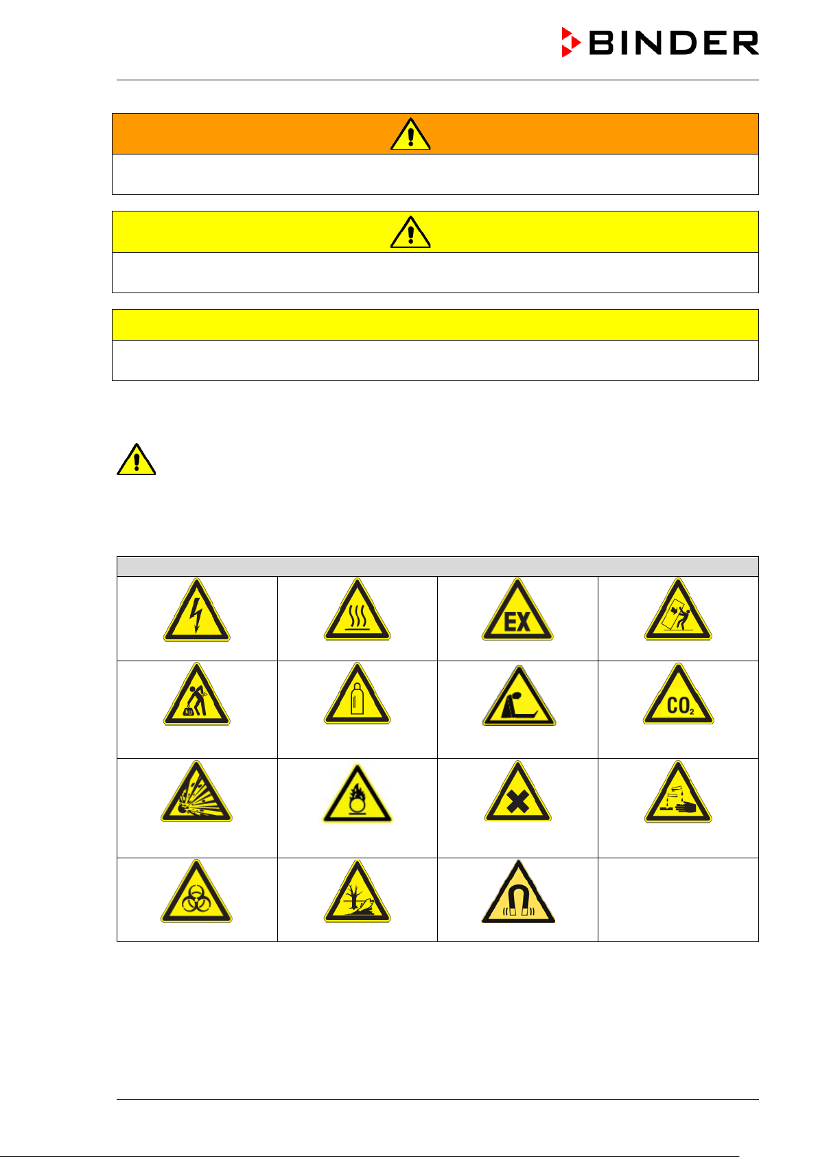
Warning signs
Electrical hazard
poisoning hazard
or chemical burns
Biohazard
Pollution Hazard
Magnetic field
WARNING
Indicates a potentially hazardous situation which, if not avoided, could result in death or serious
(irreversible) injury.
CAUTION
Indicates a potentially hazardous situation which, if not avoided, may result in moderate or mi nor
(reversible) injury.
CAUTION
Indicates a potentially hazardous situation which, if not avoided, may result in damage to the product
and/or its functions or of a property in its prox i m i ty.
1.2.2 Safety alert symbol
Use of the safety alert symbol indicates a risk of injury.
Observe all measures that are marked with the safety alert symbol in order to avoid death or
injury.
1.2.3 Pictograms
Lifting hazard
Explosive substances
Hot surface
Gas cylinders
Fire promoting agents
Explosive atmosphere
Suffocation hazard
Harmful substances
Stability hazard
suffocation and
CO
2
Risk of corrosion and /
CB (E7) 06/2018 Page 8/174
Page 9
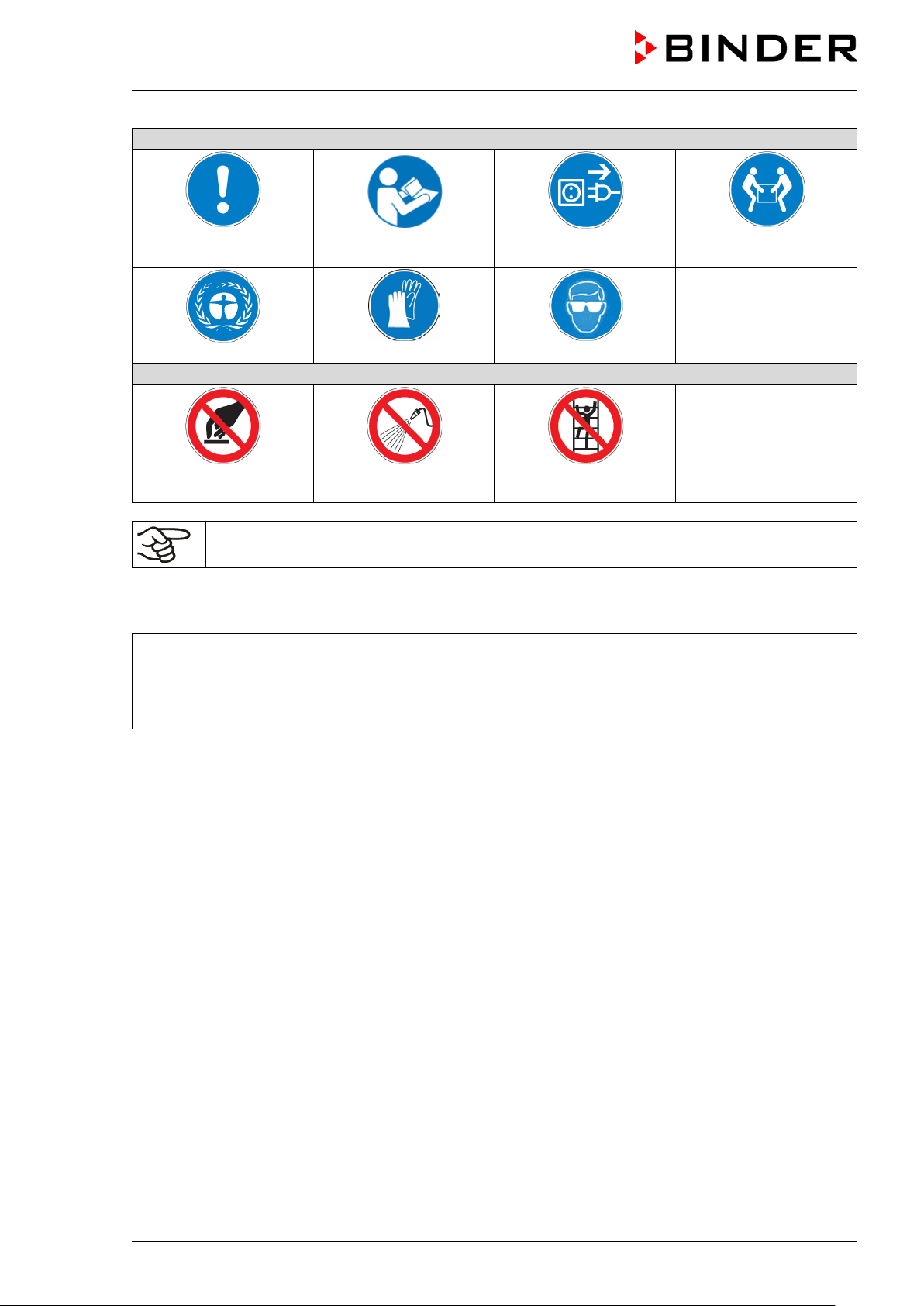
Mandatory action signs
plug
Environment protection
Prohibition signs
water
Mandatory regulation
Do NOT touch
Information to be observed in order to ensure optim um function of the product.
Read operating
instructions
Wear protective gloves
Do NOT spray with
1.2.4 Word message panel structure
Type / cause of hazard.
Possible consequences.
Instruction how to avoid the hazard: prohibition
Instruction how to avoid the hazard: mandatory a ct i on
Disconnect the power
Wear safety goggles
Do NOT climb
Lift with several persons
Observe all other notes and information not necessarily emphasized in the same way, in order to avoid
disruptions that could result in direct or indirect injury or property damage.
CB (E7) 06/2018 Page 9/174
Page 10
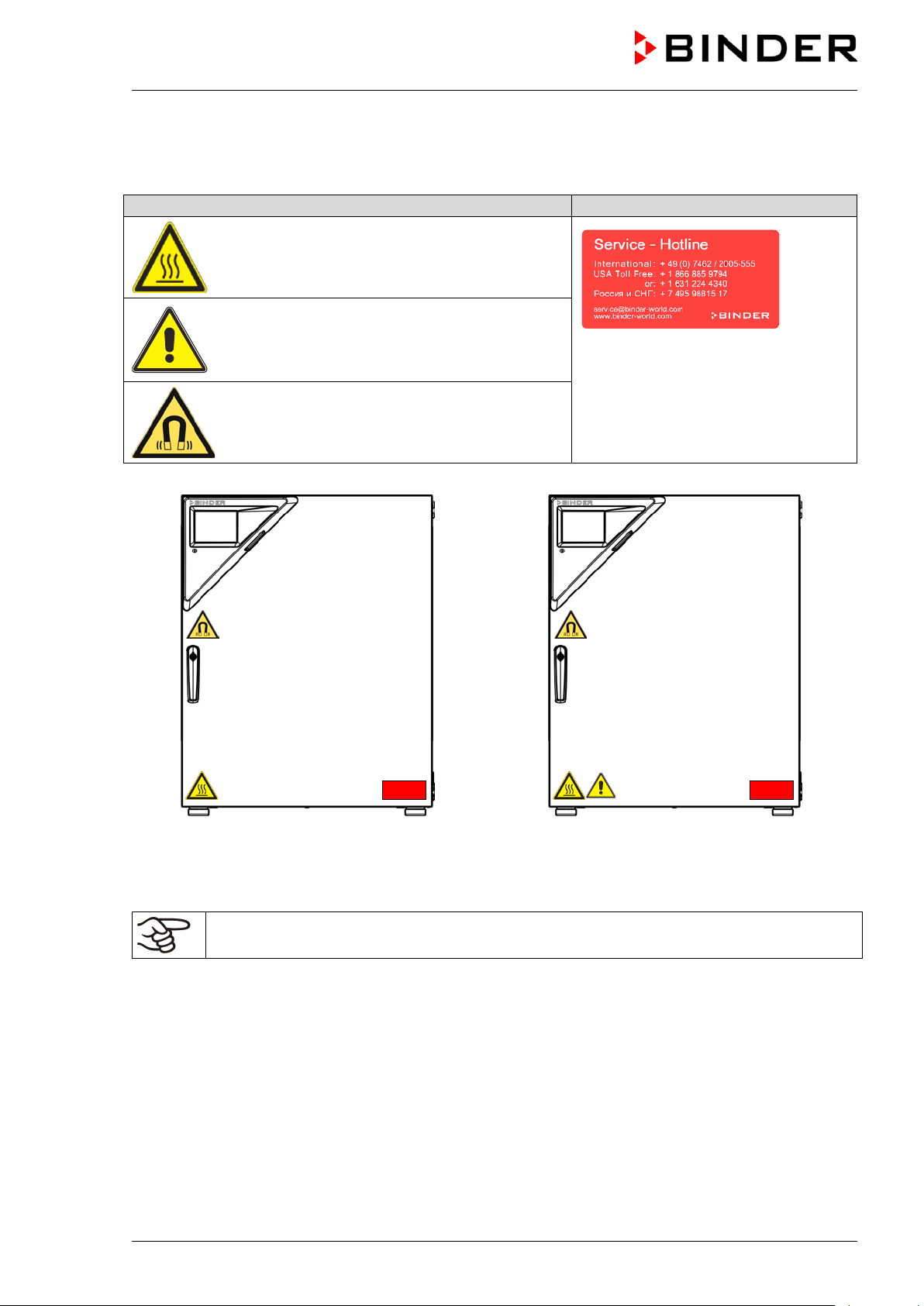
Pictograms (Warning signs)
Service label
1.3 Localization / position of safety labels on the chamber
The following labels are located on the chamber:
Hot surface
• on the outer chamber door
Risk of injury
• on the outer door: CB-UL onl y
• above the access ports (option)
Magnetic field
• on the outer door above the door handle
CO2 incubator CB CO2 incubator CB-UL
Figure 1: Position of labels on the chamber
Keep safety labels complete and legible.
Replace safety labels that are no longer legible. Contact BINDER service for these replacements.
CB (E7) 06/2018 Page 10/174
Page 11
Indications of the type plate (example)
Information
BINDER
Manufacturer: BINDER GmbH
CB 170
Model designation
CO2 incubator
Device name
Serial No.
00000000000000
Serial no. of the chamber
Built
2018
Year of construction
Nominal
187 °C
369 °F
IP protection
20
IP type of protection acc. to standard EN 60529
Temp. safety device
DIN 12880
Temperature safety device acc. to standard DIN 12880
Class
3.1
Class of temperature safety device
Art. No.
9040-0131
Art. No. of the chamber
Project No.
---
Optional: Special application acc. to project no.
1,30 kW
Nominal power
200-230 V / 50 Hz
200-230 V / 60 Hz
1 N ~
Current type
5,7 A
Nominal current
Symbol on the type plate
Information
Nominal temp.
187 °C
1,30 kW / 5,7 A
369 °F
200-230 V / 50 Hz
IP protection
20
200-230 V / 60 Hz
Safety device
DIN 12880
1 N ~
Class
3.1
Art. No.
9040-0131
Project No.
Built
2018
CO2 incubator
BINDER GmbH
www.binder-world.com
CB 170
Serial No. 00000000000000
1.4 Type plate
Position of type plate: left chamber side (see n from front), at the bottom in the middle
temperature
Im Mittleren Ösch 5
78532 Tuttlingen / Germany
E7
Made in Germany
Figure 2: Type plate (example of CB 170 regular chamber)
Nominal temperature
Nominal voltage range +/-10%
at the indicated power frequency
CE conformity marking
Electrical and electronic equipment manufactured / placed
on the market in the EC after 13 August 2005 and to be
disposed of in separate collection according to Directive
2012/19/EU on waste electrical and elect ronic equipment
(WEEE).
CB (E7) 06/2018 Page 11/174
Page 12
1.5 General safety instructions on instal l ing and operating the CO2 incubator
With regard to operating the chamber and to the installation location, please observe the guideline
BGI/GUV-I 850-0 on safe working in laboratories (formerly BGR/GUV-R 120 or ZH 1/119 laboratory
guidelines issued by the employers’ liabilit y insurance association) (for Germany).
BINDER GmbH is only responsible for the safety features of the chamber provided skilled electricians or
qualified personnel authorized by BINDER perform all maintenance and repair, and if components
relating to chamber safety are replaced in the event of failure with original spare parts.
To operate the chamber, use only original BINDER accessories or accessories from third-party suppliers
authorized by BINDER. The user is responsible for any risk caused by using unauthorized acces sories.
CAUTION
Danger of overheating.
Damage to the chamber.
∅ Do NOT install the chamber in unventilated recesses.
Ensure sufficient ventilation for dispersal of the heat.
Do not operate the chamber in hazardous locations.
DANGER
Explosion hazard.
Danger of death.
∅ Do NOT operate the chamber in potentially explosive areas.
KEEP explosive dust or air-solvent mixtures AWAY from the chamber.
The chamber does not dispose of any measures of explosion protection.
DANGER
Explosion hazard.
Danger of death.
∅ Do NOT introduce any sub st ance into the chamber which is combustible or explosive at
working temperature.
∅ NO explosive dust or air-sol vent mixture in the inner chamber.
Any solvent contained in the charging material must not be explosive or inflammable. I.e., irrespective of
the solvent concentration in the steam room, NO explosive mixture with air must form. The temperature
inside the chamber must lie below the flash point or below the sublimation point of the charging material.
Familiarize yourself with the physical and chemical properties of the charging material, as well as the
contained moisture constituent and its behavior with the addition of heat energy and humidity (chamber
with active humidification).
Familiarize yourself with any potential health risks caused by the charging material, the contained
moisture constituent or by reaction products which may arise during the temperature process. Take
adequate measures to exclude such risks prior t o putting the chamber into operation.
DANGER
Electrical hazard.
Danger of death.
∅ The chamber must NOT become wet during operation or m ai ntenance.
The chambers were produced in accordance with VDE regulations and were routinely tested in
accordance to VDE 0411-1 (IEC 61010-1).
CB (E7) 06/2018 Page 12/174
Page 13
During and after a sterilization the temperature of the inner surfaces almost equals the set-point.
CAUTION
The inner doors, the inner door and glass door handles, and the inner cham ber will
become hot during a sterilization.
Danger of burning.
∅ Do NOT touch the inner doors, the inner door and glass door handles, and the inner
surfaces after a sterilization.
WARNING
Stability hazard.
Danger of injury.
Damage to the chamber and the charging material.
Housing cover breakaway.
∅ Do NOT climb on the lower housing cover.
∅ Do NOT load the lower housing cover with heavy objects while the chamber door is
open.
1.6 Precautions when working with gases
Notes on handling carbon dioxide (CO2)
Carbon dioxide (CO
and therefore practically imperceptible. Vent out any CO
or a suitable connection to an exhaust sy st em. We recommend installing a CO
) in high concentrations is hazardous to health. It is colorless and almost odorless
2
gas that may escape via good room ventilation
2
warning system
2
WARNING
High concentration of CO2 (> 4 Vol.-%).
Risk of death by suffocation.
Danger of poisoning.
∅ Do NOT set up chambers in non-ventilated recesses.
Ensure technical ventilation measures.
Observe the relevant regulations for handling CO
.
2
Chamber with O
Oxygen (O
2
control: Notes on handling oxygen (O2)
2
) is colorless and almost odorless and therefore practically imperceptible. It promotes burns,
which can proceed explosively. There is a fire hazard for flammable oxygenated materials, e.g. clothes
and hair. O
is heavier than air and may accumulate in low-lyin g areas.
2
WARNING
High concentration of O2 (> 21 % O2).
Fire and explosion hazard through contact of combustible materials with O
.
2
Risk of burns and other injuries.
∅ Do NOT set up chambers in non-ventilated recesses.
Ensure technical ventilation measures.
Observe the relevant regulations for handling O
.
2
CB (E7) 06/2018 Page 13/174
Page 14
t and necessary safety
Make sure gas tightness of all gas connections by checking them for leaks (e.g. with leak
equipment with oil or fat. Use only materials and spare parts which are
Strictest smoking ban and no ignition sources in areas where oxygen enrichment is
Make sure good ventilation of areas where oxygen enrichment is possible (location of the
enriched atmosphere must keep away
from ignition sources (flames, cigarettes, etc.) and ventilate their clothes at least 15
Take appropriate measures to prevent oxygen enrichment and fire and explosion hazards in areas where
oxygen enrichment is possible.
General information for safe handling of oxygen:
• Make sure training of personnel on hazards of oxygen enrichmen
measures.
• Make sure adequate labeling of all oxygen equipment and facilities.
•
spray or diluted soap solution).
• Close the main valve of the source of ox ygen after work when not using the chamber.
• Never lubricate O
2
approved for use with oxygen.
• Regularly inspect fire extinguishers for proper condition.
• Set up emergency showers where oxygen enrichment is possible.
•
possible.
•
chamber and/or O2 cylinders.
• Persons who may have been in a possibly oxygenminutes.
• Always keep emergency routes free.
Chamber with O2 control: Notes on handling nitrogen (N2)
Nitrogen (N
therefore practically imperceptible. Any N
) in high concentrations is hazardous to health. It is colorless and almost odorless and
2
gas that may escape must be safely led out via good room
2
ventilation or a suitable connection to an exhaust system .
High concentration of N2.
Risk of death by suffocation.
∅ Do NOT set up chambers in non-ventilated recesses.
Ensure technical ventilation measures.
Observe the relevant regulations for handling N
WARNING
.
2
CB (E7) 06/2018 Page 14/174
Page 15
Always close the valve even with apparently empty cylinders; screw on the cap when not in
1.7 Precautions when handling gas cylinders
General information for safe handling of gas cy li nders:
• Store and use gas cylinders only in well-ventilated locations.
• Open the gas cylinder valve slowly to avoi d pressure surges.
• Secure gas cylinders during storage and use against falling (chaining).
• Transport gas cylinders with a cylinder cart, do not carry, roll, or throw them.
•
use. Return gas cylinders with the valve closed.
• Do not open gas cylinders by force. Mark them when damag ed.
• Protect gas cylinders against fire, e.g. do not store together with flammable liquids.
• Observe relevant regulations for dealing with gas cylinders.
Secure the gas cylinders against falling and other m echanical damage.
WARNING
Safety valve tearing off.
Sudden release of the stored pressure energy.
Risk of injury.
Secure gas cylinders against falling (chaining).
Transport gas cylinders with a cylinder cart.
The valve of the gas cylinder always must be clo sed before screwing on or unscrewing the gas hose.
WARNING
Opening the cylinder valve when the cylinder is not connected.
Sudden release of the stored pressure energy.
Risk of injury.
Close the gas cylinder valve before connecting or removing the gas hose.
After connecting the gas cylinder, check all gas connections for leaks (e.g. with leak spray or
diluted soap solution).
CB (E7) 06/2018 Page 15/174
Page 16
introduce any substance combustible or explosive at working temperature into
1.8 Intended use
Series CB incubators are suitable for the cultivation of mammal cells under typical conditions of approx.
37 °C / 98.6°F. The chamber permits setting defined pH conditions by common NaHCO
of commercial cell media by keeping an exact CO
atmosphere inside. The chambers guarantee high
2
humidity inside to avoid osmolarity increasin g caused by the evaporation of the cell media.
buffer systems
3
With the chamber w ith O
control, a variable oxygen atmosphere can additionally influence the growth of
2
the cells.
The chambers are suitable for exact conditioning of harmless materials. Any possible solvent any solvent
must not be explosive and flammable. Components of the charging material must NOT form an explosive
mixture with air. The operating temperature must lie below the flash point or below the sublimation point
of the charging material. Any component of the charging material must NOT be able to release toxic
gases.
DANGER
Explosion or implosion hazard.
Danger of poisoning.
Danger of death.
∅ Do NOT
the chamber, in particular no energy sources such as batteries or lithium-ion batteries.
∅ NO explosive dust or air-sol vent mixture in the inner chamber.
∅ Do NOT introduce any substance which could lead to release of toxic gases.
Other applications are not approved.
Following the instructions in this operating manual and conducting regular maintenance work
(chap. 22.1) are part of the intended use.
The chambers are not classified as medical devices as defined by the Medical Device Directive
93/42/EEC.
Due to the special demands of the Medical Device Directive (MDD), these chambers are not
qualified for sterilization of medical devic es as defined by the directive 93/42/EWG.
WARNING: If customer should use a BINDER cham ber running in non-supervised
continuous operation, we strongly recomm end in case of inclusion of irrecoverable specime n
or samples to split such specimen or samples and store them in at least two chambers, if thi s
is feasible.
The charging material shall not contain any corrosive ingredients that may damage the
machine components made of stainless steel, al um i num, and copper. Such ingredients
include in particular acids and halides. Any cor rosive damage caused by such ingredients is
excluded from liability by BINDER GmbH.
In case of foreseeable use of the chamber there is no risk for the user through the integration of the
chamber into systems or by special environmental or operating conditions in the sense of EN 610101:2010. For this, the intended use of the chamber and all its connections must be observed.
CB (E7) 06/2018 Page 16/174
Page 17

1.9 Measures to prevent accidents
The manufacturer took the following measures to prevent dangers:
• Indications on the type plate
See operating manual chap. 1.4.
• Operating manual
An operating manual is available for each chamber.
• Overtemperature monitoring
The chamber is equipped with a temperature display, which can be read from outside.
The chamber is equipped with an additional safety controller (temperature safety device class 3.1 acc.
to DIN 12880:2007). Visual and audible (buzzer) signals indicate temperature exceeding.
• Safety, measurement, and control equipment
The safety, measuring, and control equipment i s easily accessible.
• Electrostatic charge
The interior parts are grounded.
• Non-ionizing radiation
Non-ionizing radiation is not intentionally produced, but released only for technical reasons by
electrical equipment (e.g. power cables). The machine is equipped with a permanent magnet located
behind the inner panel of the outer chamber door. If persons with active implants (e.g. pacemakers,
defibrillators) keep a safe distance (distance of field source to implant) of 30 cm, an influence of these
implants can be excluded with high probability.
• Protection against touchable surfaces
Tested according to EN ISO 13732-1:2008.
• Floors
See operating manual chap. 3.4 for correct installation
• Cleaning
See operating manual chap. 21.
CB (E7) 06/2018 Page 17/174
Page 18

Maximum work place
threshold limit value
Tolerated concentration
with permanent load
Substance
Formula
ppm
mg/m3
ppm
mg/m3
Ammonia
NH3
20
14
5500
4000
Acetone
CH3COCH3
500
1200
3300
8000
Benzene
300
1200
150000
Chlorine
Cl2
0.5
1.5
0.7 2 Acetic acid
CH3COOH
10
25
800
2000
Ethyl acetate
CH3COOC2H5
400
1400
4000
15000
Ethanol
C2H5OH
500
960
3500
6000
Ethylene glycol
HOCH2CH2OH
10
26
1200
3000
Formaldehyde
HCHO
0.3
0.37
2400
3000
Isopropanol
(CH3)2CHOH
200
500
4800
12000
Methanol
CH3OH
200
260
3500
6000
Methyl ethyl ketone
C2H5COCH3
200
590
3300
8000
Ozone
O3
0.1
0.2
0.5 1 Hydrochloric acid
HCl 2 3
300
500
Hydrogen sulphide
H2S
10
15
350
500
Nitrogen oxides
NOx
5 9 5 9 Sulphur dioxide
SO2
5
13 5 13
Toluol
C6H5CH3
100
380
1300
5000
Xylene
C6H4(CH3)2
100
440
1300
5000
1.10 Resistance of the humidity sensor against harmful substances
The following list of harmful substances refers only to the humidity sensor and does not include any other
materials incorporated in the chamber or prohibited substances in relation to explosion protection.
Some gases - especially clean gases - do not have any influence on the humidity sensor. Others do have
a very small influence, whereas others may influence the sensor to a larger extent.
• The following gases do not influence the sensor and the humidity measurement: Argon (Ar), carbon
dioxide (CO2),helium (He), hydrogen (H2), neon (Ne), nitrogen (N2), nitrous oxide (N2O), oxygen (O2)
• The following gases do not or to a minor extent influence the sensor and the humidity measurement:
Butane (C
• The following gases do not, or to a minor extent influence the sensor and the humidity measurement,
provided that the indicated loads are not ex ceeded:
), ethane (C2H6), methane (CH4), natural gas propane (C3H8)
4H10
These values are to be considered as approximate values. The sensor resistance largely depends on
the temperature and humidity conditions during the time of exposure to harmful substances. Avoid
simultaneous condensation. Tolerated error of measurement: ± 2 %r.H. The maximum work place
threshold limit value is one that can be regarded a s harmless for humans.
• Vapors of oil and fat are dangerous for the sensor because they may condensate at the sensor and
thus prevent its function (insulating layer). For similar reasons it is not possible to measure smoke
gases.
CB (E7) 06/2018 Page 18/174
Page 19

2. Chamber description
The CO2 incubators CB are equipped with a multifunctional microprocessor display controller for
temperature, CO
humidification) and a digital display accurate to one-tenth of a degree resp. 0.1 vol.-%. With its
comprehensive program control functions, the display program controller MB2 permits the high precision
performance of temperature, CO
humidification) cycles.
Material: The inner chamber, the pre-heating chamber and the inside of the doors are all made of
stainless steel V2A (German material no. 1.4301, US equivalent AISI 304). The inner surfaces are
smooth and therefore easy to clean. The inner chamber is deep-drawn from one piece, polished (suitable
for pharmaceutical applications) and has no welds or inaccessible corners. The hinges and the seal of the
inner glass door are glued from the outside to aid cleaning of the inner chamber. When operating the
chamber at high temperatures (sterilization), the impact of the oxygen in the air may cause discoloration
of the metallic surfaces (yellowish-brown or blue) by natural oxidation processes. These colorations are
harmless and will in no way impair the function or quality of the chamber. The perforated shelves are also
made of stainless steel. You can insert a maximum of 3 (CB 56), 6 (CB 170), resp. 8 (CB 220) shelves.
The housing is RAL 7035 powder-coated. All corners and edges are also completely coated.
Door lock: The DuoDoor™ door lock offers two to open the outer door and glass door independently or
together. The outer door is regularly equipped with a door lock with keys.
, and O2 (chamber with O2 control) levels and humidity (chamber with active
2
, O2 (chamber with O2 control), and humidity (chamber with active
2
Sterilization: The chamber’s heating system permits hot-air auto-sterilization at a setpoint of 187.5 °C /
369.5°F. Thus, a temperature of 180 °C / 356°F is maintained for at least 30 minutes on all internal
surfaces, resulting in sterilization of the entire inner chamber. Therefore, this procedure meets all
international guidelines regarding hot air sterilization, e.g. AAMI ST63, DIN 58947, European
Pharmacopoeia.
Temperature safety device Thanks to the regular safety controller (temperature safety device class 3.1
acc. to DIN 12880:2007), the set temperature is maintained in case of failure.
system: A highly precise, drift-free CO2 infrared measuring system in combination with the
CO
2
permanent mixture of CO
allows precise and constant CO
gas through a special proprietary gas mixing head developed by BINDER
2
concentrations for long periods. This creates optimum growth conditions
2
for cultures. The gas enters the chamber via a fine filter (aseptic filter) with a high filtration efficiency that
also filters the smallest particles.
Fast reaction times, maximum accuracy and selectivity characterize the CO
CB incubator series. The accuracy of the CO
measuring system is based on an infrared measuring cell
2
measuring procedure of the
2
with NDIR (non-dispersive infrared) sensor, which continuously regulates to a reference value. Therefore,
disturbance variables and aging phenomena in the measuring system are almost completely eliminated,
so that this measuring system, in contrast to other measuring procedures, remains practically drift-free
between calibrations and is entirely selective for CO
. The sensor is built into the chamber and can be
2
sterilized.
The accuracy of the indicated values of CO
per 10 mbar / 0.15 psi). To compensate for this effect in the CO
depends on the ambient air pressure (approx. 0.08 vol.-%
2
measurement, the altitude of the
2
installation site is entered into the controller.
O
control (chamber with O2 control): The CO2 incubator is available with O2 control in addition to CO2
2
control. There are two different control ranges:
• Regular equipment: Hypoxic control range 0.2 to 20 vol. % O
concentration; it is not possible to connect O2 gas bottles to increase O2 concentration. Control in
O
2
the low O
• Alternative control range 10 to 95 vol. % O
particular for hyperoxic applications (> 21 vol. % O
between 10 and 20 vol. % O
The O
2
range is very precise, in particular in the ra nge below 1 vol. % O2.
2
(option). Although the high control range is intended in
2
.
2
), it is also suitable for slightly hypoxic applications
2
sensor is a semiconductor gas sensor with Z rO2 ceramic.
. Only N2 can be connected to reduce
2
CB (E7) 06/2018 Page 19/174
Page 20
Humidity control (chamber with active humidification): The chamber is available with humidity control
and a microprocessor-controlled humidification system .
Freshwater is supplied by manually filling a freshwater bag, which is placed behind the chamber door in a
recess.
A resistance humidifying system humidifies the air. For this purpose, use deionized (demineralized)
water. The option BINDER Pure Aqua Service allows using the chamber with any degree of water
hardness.
Controller: The efficient program controller is equipped with a multitude of operating functions, in
addition to recorder and alarm functions. Programming of test cycles is easily accomplished via the
modern MB2 touch screen controller and is also possible directly with a computer via Intranet in
connection with the BINDER communication software APT-COM™ 3 DataControlSystem (option, chap.
18.1). The chambers are equipped with an Ethernet interface for computer communication. The APT-
COM™ 3 software permits networking up to 30 chambers and connecting them to a PC for controlling
and programming, as well as recording and representing temperature, CO
further options, see chap. 25.5.
Temperature range: 4 °C / 7.2 °F above ambient temperature up to +60 °C / 140 °F
and O2 and humidity data. For
2
Temperature range
(chamber with O
CO2 range: 0 vol.-% up to 20 vol.-%
O2 range
(chamber with O
Humidity range
(chamber with active humidification):
control):
2
control):
2
6 °C / 10.8 °F above ambient temperature up to +60 °C / 140 °F
0.2 vol.-% up to 20 vol.-% (hypoxic control range)
or 10 vol.-% up to 95 vol.-% (optional alternative control range)
60 % r.h. up to 93 % r.h.
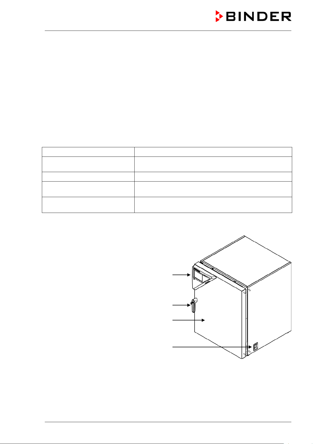
2.1 Chamber overview
Instrument panel with microprocessor controller
T4.12 and USB interface
Door handle
Chamber door
Main power switch
Figure 3: CO2 incubator CB (example: model CB 170)
CB (E7) 06/2018 Page 20/174
Page 21
(K)
(
(
(M)
(A)
(B)
(C)
(D)
(
(
(F)
(E)
(
(I)
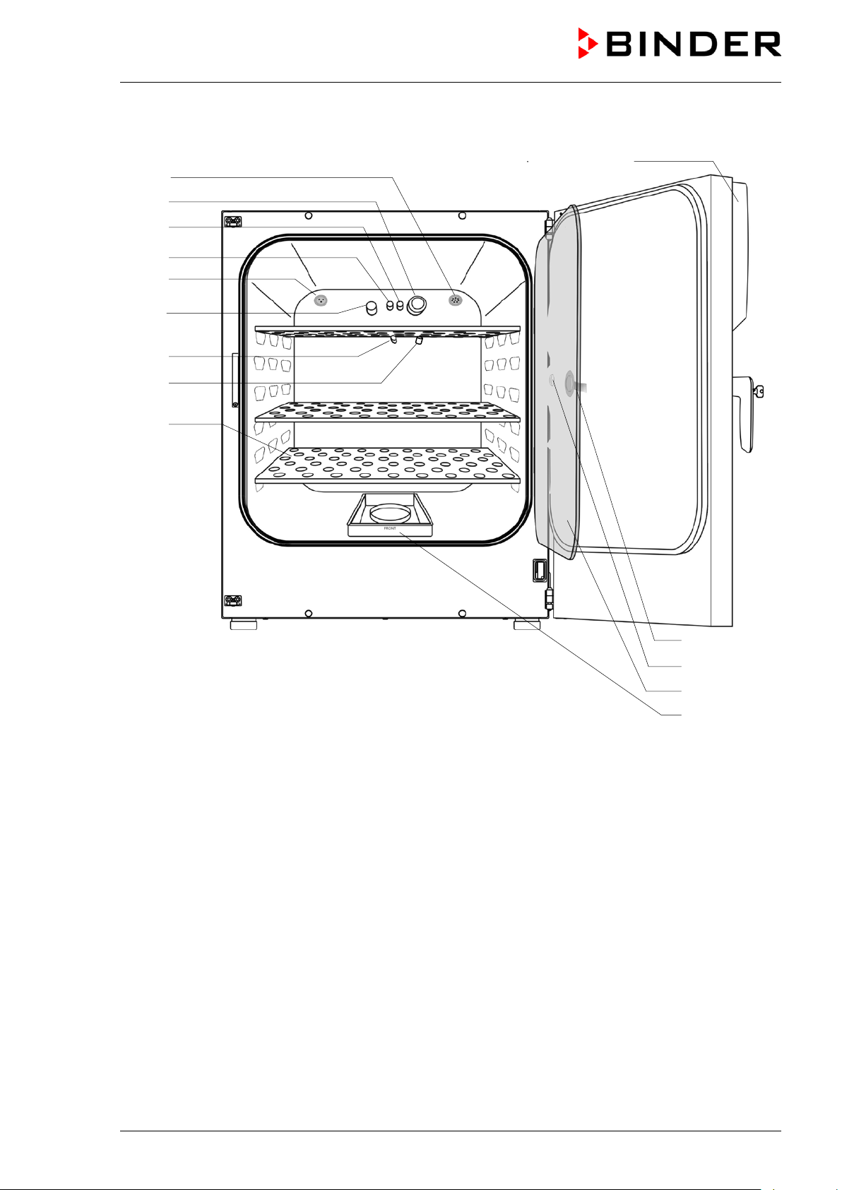
2.2 Inner chamber
D2)
H)
G)
J)
L)
Figure 4: CB 170 with O
control and options
2
(A) Instrument panel with microprocessor program controller MB2, indicating temperature, CO
(chamber with O
control) and humidity (chamber with active hum idification)
2
, O2
2
(B) Connection socket for extra-low voltage supply (option, chap. 18.6)
(C) CO
(D) Gas mixing head CO
(D2) Additional gas mixing head O
sensor
2
2
/ N2 (chamber with O2 control)
2
(E) Pt 100 temperature probe
(F) O
sensor (chamber with O2 control)
2
(G) Humidity sensor (chamber with active humidification)
(H) Internal socket 230V (max. 3 A) (option, available via BINDER INDIVIDUAL Customized Solutions,
chap. 18.3)
(I) Perforated shelves, made of stainless steel
(J) Glass door handle
(K) Measuring access port
(L) Inner glass doors
(M) Permadry™ water pans
CB (E7) 06/2018 Page 21/174
Page 22
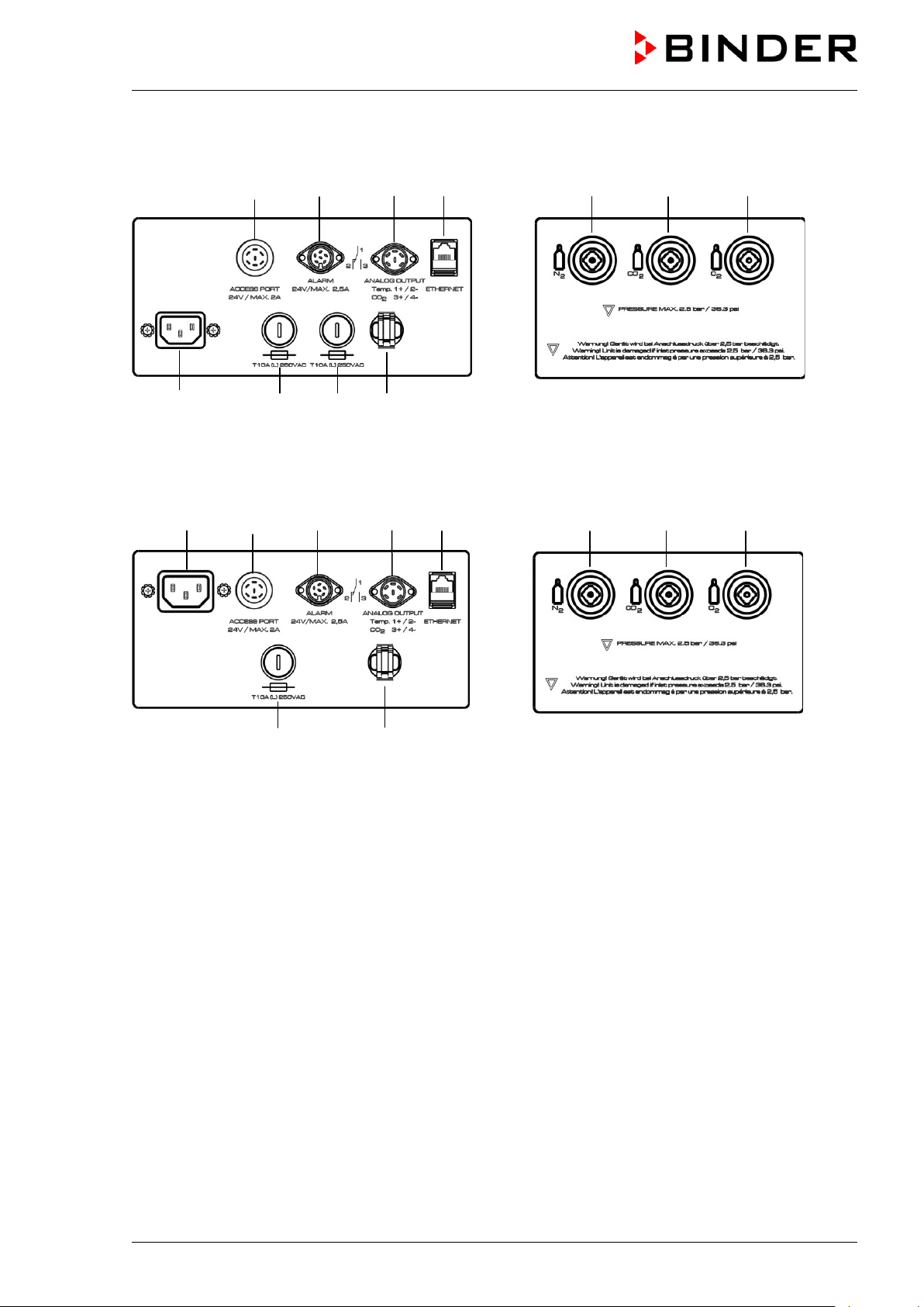
2.3 Control panel on the rear of the chamber
(2) (3) (4) (5) (9) (10) (11)
(1b) (6b) (7) (8)
Figure 5: Rear control panel CB with O
control and options
2
(1b) (2) (3) (4) (5) (9) (10) (11)
(6a) (8)
Figure 6: Rear control panel CB-UL with O
control and options
2
(1a) Socket for IEC connector plug / power cable 100-120 V AC
(1b) Socket for IEC connector plug / power cable 230 V AC
(2) External socket for extra-low voltage supply (option for CB 170 / CB 220, chap. 18.6)
(3) DIN-socket for zero-voltage relay alarm outputs
(4) DIN socket for analog outputs 4-20 mA (option, chap. 18.4)
(5) Ethernet interface for computer communication
(6a) Miniature fuse T12,5 A (L) 250 V AV for 100-120 V chamber
(6b) Miniature fuse T10 A (L) 250 V AC for 200-230 V chamber
(7) Miniature fuse T10 A (L) 250 V AC for 200-230 V chamber
(8) Strain relief for power cable
(9) Quick acting closure socket for N
(10) Quick acting closure socket for CO
(11) Quick acting closure socket for O
10 up to 95 vol.-% O
)
2
(chamber with O2 control)
2
2
(chamber with O2 control with optional alternative control range
2
CB (E7) 06/2018 Page 22/174
Page 23
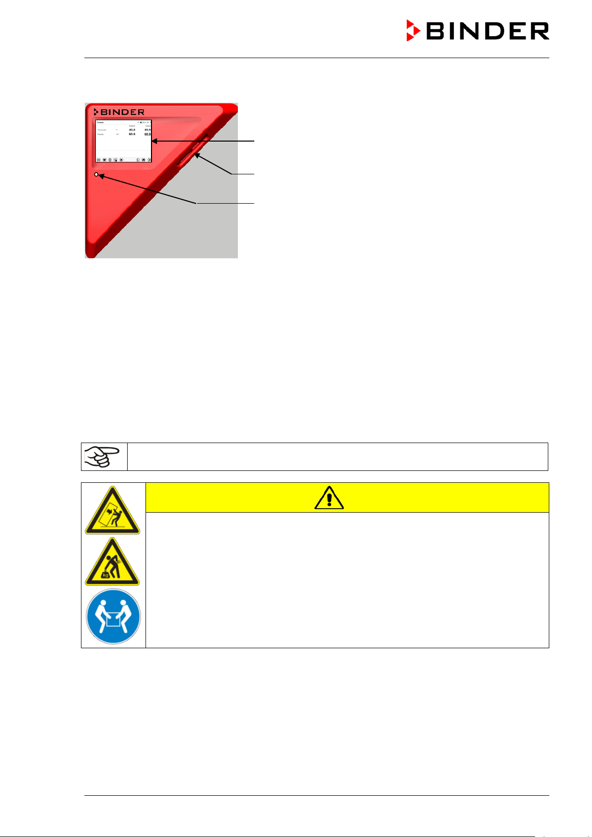
2.4 Instrument panel
MB2 controller display
5,7" with touchscreen
USB interface
Pilot lamp
Figure 7: Instrument panel with MB2 program controller and USB
interface
3. Completeness of delivery, transportation, storage, and
installation
3.1 Unpacking, and checking equipment and completeness of del ivery
After unpacking, please check the chamber and its optional accessories, if any, based on the delivery
receipt for completeness and for transportation damage. Inform the carrier immediately if transportation
damage has occurred.
The final tests of the manufacturer may have caused traces of the shelves on the inner surfaces. This has
no impact on the function and performance of the chamber.
Please remove any transportation protection devices and adhesives in/on the chamber and on the doors
and remove the operating manuals and accessory equipment.
Remove any protective lamination sheet on the inner metal surfaces prior to commissioning.
CAUTION
Sliding or tilting of the chamber.
Damage to the chamber.
Risk of injury by lifting heavy loads.
Do NOT lift or transport the chamber using the doo r handle, the door or the lower
housing.
Lift the chamber from the pallet at the four lower corners with the aid of four people.
If you need to return the chamber, please use the original packing and observe the guidelines for safe
lifting and transportation (chap. 3.2).
For disposal of the transport packing, see chap. 23.1.
Note on second-hand chambers (Ex-Demo-Units):
Second-hand chambers are chambers that were used for a short time for tests or exhibitions. They are
thoroughly tested before resale. BINDER ensures that the chamber is technically sound and will work
flawlessly.
Second-hand chambers are marked with a sticker on the chamber door. Please remove the sticker before
commissioning the chamber.
CB (E7) 06/2018 Page 23/174
Page 24
3.2 Guidelines for safe lifting and transportation
After operation, please observe the guidelines for temporary decommissioning (chap. 23.2). Empty the
Permadry™ water pan before moving the chamber. In case of any spilling of the contents, shut down the
chamber and dry it out carefully and completely.
CAUTION
Sliding or tilting of the chamber.
Damage to the chamber.
Risk of injury by lifting heavy loads.
Transport the chamber in its original packaging only.
For moving or shipping, secure the chamber with transport straps.
∅ Do NOT lift or transport the chamber using the door handle, the door or the lowe r
housing.
Lift the chamber at the four lower corners with the aid of 4 peopl e and place it on a
rolling pallet.
Move the chamber to the desired location and lif t it from the rolling pallet with the aid of
four people.
• Permissible ambient temperature ran ge during transport: 10 °C / 14 °F to +60 °C / 140 °F.
You can order transport packing for moving or shipping purposes from BINDER service.
Permissible ambient temperature range during transport:
• If the humidifying system has NOT been emptied: +3 °C / 37.4 °F to +60 °C / 140 °F.
• After BINDER Service has emptied the humidi fying system: -10 °C / 14 °F to +60 °C / 140 °F.
With temperatures below +3 °C / 37.4 °F, water must be completely removed from the humidifying
system.
CAUTION
Transport below +3 °C / 37.4 °F with filled steam humidifying system.
Freezing in the steam generator.
Damage to the chamber.
Contact BINDER Service before any transportati on below +3 °C / 37.4 °F.
3.3 Storage
Intermediate storage of the chamber is possible in a closed and dry room. Observe the guidelines for
temporary decommissioning (chap. 23.2).
Permissible ambient temperature range during storage:
• the humidifying system has NOT been emptied: +3 °C / 37.4 °F to +60 °C / 140 °F.
• After BINDER Service has emptied the humidi fying system: -10 °C / 14 °F to +60 °C / 140 °F
With temperatures below +3 °C / 37.4 °F, water must be completely removed from the humidifying
system.
CAUTION
Storage below +3 °C / 37.4 °F with filled steam humidifying system.
Freezing in the steam generator.
Damage to the chamber.
Contact BINDER Service before any transportati on below +3 °C / 37.4 °F.
CB (E7) 06/2018 Page 24/174
Page 25
Only then, shut down the chamber at the main power switch (1) and empty the
Permissible ambient humidity: max. 70 % r.H., non-condensing.
CAUTION
Condensation by excess humidity.
Danger of corrosion on the housing after operating at humidity values > 70 % r.H.
for a long period.
Let the chamber dry for several days before shut-down:
• Empty the Permadry water pan.
• Chamber with active humidificat ion: Turn off humidity control (chap. 6.8).
• Set the temperature set point to 60 °C / 140 °F for approx. 2 hours.
•
freshwater bag.
When after storage in a cold location you transfer the chamber to its warmer installation site,
condensation may form. Before start-up, wait at least one hour until the chamber has attained ambient
temperature and is completely dry.
Chamber with active humidification: In case of a prolonged temporal decommissioning: Leave the
chamber door open or remove the optional ac cess port plugs.
3.4 Location of installation and ambient conditions
Notes on the location of installation
Set up the chamber on a flat, even surface, free from vibration and in a well-ventilated, dry location. The
chambers are designed for setting up inside a building (indoor use).
Freestanding chamber are suitable for installation on tables or on the optionally available stand (height
200 mm / 0.5 ft). Note: The site of installation must be capable of supporting the chamber’s weight (see
technical data, chap.25.4).
Align the chamber using a spirit level to ensure even covering of the cell-cultures with the medium. For
this purpose, manually adjust the four chamber feet.
The chambers can be stacked on top of each other (two chambers maximum). For safe stacking that is
easy to maintain, use the original BINDER stacking stand (chap. 18.8.1) or the stacking adapter (chap.
18.8.2).
To completely separate the chamber from the power supply, you must disconnect the power plug. Install
the chamber in a way that the power plug is ea sil y accessible and can be easily pulled in case of danger.
For the user there is no risk of temporary ov ervoltages in the sense of EN 61010-1:2010.
In order to avoid contamination, never place the chamber directly on the floor.
CAUTION
Danger of overheating.
Damage to the chamber.
∅ Do NOT set up chambers in non-ventilated recesses.
Ensure sufficient ventilation for dispersa l of the heat.
Do not install or operate the chamber in potentially explosive areas.
DANGER
Explosion hazard.
Danger of death.
∅ Do NOT operate the chamber in potentially explosive areas.
KEEP explosive dust or air-solvent mixtures AWAY from the vicinity of the chamber.
CB (E7) 06/2018 Page 25/174
Page 26
Ambient conditions
• Permissible ambient temperature ran ge for operation: +18 °C / 64.4 °F to +30 °C / 86 °F
At elevated ambient temperature values, f l uct uations in temperature and humidity may occur.
• Ideal ambient temperature: at least 7 °C / 12.6 °F below the intended working temperature. E.g.,
working temperature 37 °C / 98.6 °F = ambient temperature 30 °C / 86 °F and lower. In the event of
working temperatures of less than 7 °C / 12.6 °F above the ambient temperature, the setpoint can be
exceeded.
The ambient temperature should not be substanti al ly higher than the indicated ambient
temperature of 22 +/-3 °C / 71.6 +/-5.4 °F to which the specified technical data relates. For
other ambient conditions, deviations from the indicated data are possible.
Avoid direct solar radiation on the chamber.
• Permissible ambient humidity : 70 % r.H. max., non-condensing.
• Installation height: max. 2000 m / 6561.7 ft above sea level.
• Wall distances: rear 100 mm / 3.94 in, sides 50 mm / 1.97 in.
To completely separate the chamber from the pow er supply, you must disconnect the power
plug. Install the chamber in a way that the po wer plug is easily accessible and can be easily
pulled in case of danger.
Notes on handling carbon dioxide (CO
Carbon dioxide (CO
) in high concentrations is hazardous to health. It is colorless and almost odorless
2
and therefore practically imperceptible. Vent out any CO
or a suitable connection to an exhaust sy st em . We recommend installing a CO
)
2
gas that may escape via good room ventilation
2
warning system.
2
WARNING
High concentration of CO2 (> 4 Vol.-%).
Danger of death by suffocation.
Danger of poisoning.
∅ Do NOT set up chambers in non-ventilated recesses.
Ensure technical ventilation measures.
Observe the relevant regulations for handling C O
Observe the occupational exposure limit OEL for CO2 set by the national authorities (formerly
maximum permitted workplace concentration). Check compliance when operating all chambers located in
the room.
3
• OEL for Germany : 5000 ml/ m
(ppm) = 0,5 Vol.-%
.
2
• CO
lost from CB 170 at 5 vol.-% CO2 with each opening the door: about 14.8 g, i.e. 0.00758 cubic
2
meters / 0.268 cubic feet (under normal pressure)
• CO
lost during 12h at 5 vol.-% without opening the door: approx. < 2 g, i.e. 0.001 cubic meter / 0.035
2
cubic feet (under normal pressure 1013 mbar / 14.7 psi)
An example of how to evaluate laboratory volume and air change rate:
Question: Is an air change rate of 1/h sufficient for a lab with a volume of 100 cubic meters /
3,531.5 cubic feet with 10 incubators CB 170, opened 4 times per hour?
Calculation: CO
concentration = CO2 lost by opening the door, multiplied by 10 incubators,
2
multiplied by opening the door 4 times per hour, divided by lab volume
CB (E7) 06/2018 Page 26/174
Page 27
t and necessary safety
sure gas tightness of all gas connections by checking them for leaks (e.g. with leak
equipment with oil or fat. Use only materials and spare parts which are
ignition sources in areas where oxygen enrichment is
Make sure good ventilation of areas where oxygen enrichment is possible (location of the
p away
from ignition sources (flames, cigarettes, etc.) and ventilate their clothes at least 15
0.00758 cubic meters x 10 x 4 div. 100 cubic meters = 0.003032, i.e. 0.303 % or 3032 ppm.
0.2676852 cubic feet x 10 x 4 div. 3,531.467 cubic feet = 0.003032, i.e. 0.303 % or 3032 ppm.
Result: The maximum permissible value of 5000 ppm is not exceeded under these operation
conditions.
Even when CO
or systems operated with CO2 are handled carefully and appropriately, a residual risk
2
remains, which can lead to life-threatening situations under certain circumstances. Therefore we strongly
recommend continuous monitoring of CO
be ensured permanently that the maximum permissible occupational exposure limit OEL for CO
% CO
for Germany) is not exceeded.
2
concentration in the ambient air of the CO2 incubator. It must
2
(0.5 vol -
2
Chamber with O
Oxygen (O
2
control: Notes on handling oxygen (O2)
2
) is colorless and almost odorless and therefore practically imperceptible. It promotes burns,
which can proceed explosively. There is a fire hazard for flammable oxygenated materials, e.g. clothes
and hair. O
is heavier than air and may accumulate in low-lyin g areas.
2
WARNING
High concentration of O2 (> 21 % O2).
Fire and explosion hazard through contact of combustible materials with O
Risk of burns and other injuries.
∅ Do NOT set up chambers in non-ventilated recesses.
Ensure technical ventilation measures.
Observe the relevant regulations for handling O
.
2
Take appropriate measures to prevent oxygen enrichment and fire and explosion hazards in areas where
oxygen enrichment is possible.
.
2
General information for safe handling of oxygen:
• Make sure training of personnel on hazards of oxygen enrichmen
measures.
• Make sure adequate labeling of all oxygen equipment and facilities.
• Make
spray or diluted soap solution).
• Close the main valve of the source of ox ygen after work when not using the chamber.
• Never lubricate O
approved for use with oxygen.
2
• Regularly inspect fire extinguishers for proper condition.
• Set up emergency showers where oxygen enrichment is possible.
• Strictest smoking ban and no
possible.
•
chamber and/or O2 cylinders.
• Persons who may have been in a possibly oxygen-enriched atmosphere must kee
minutes.
• Always keep emergency routes free.
CB (E7) 06/2018 Page 27/174
Page 28
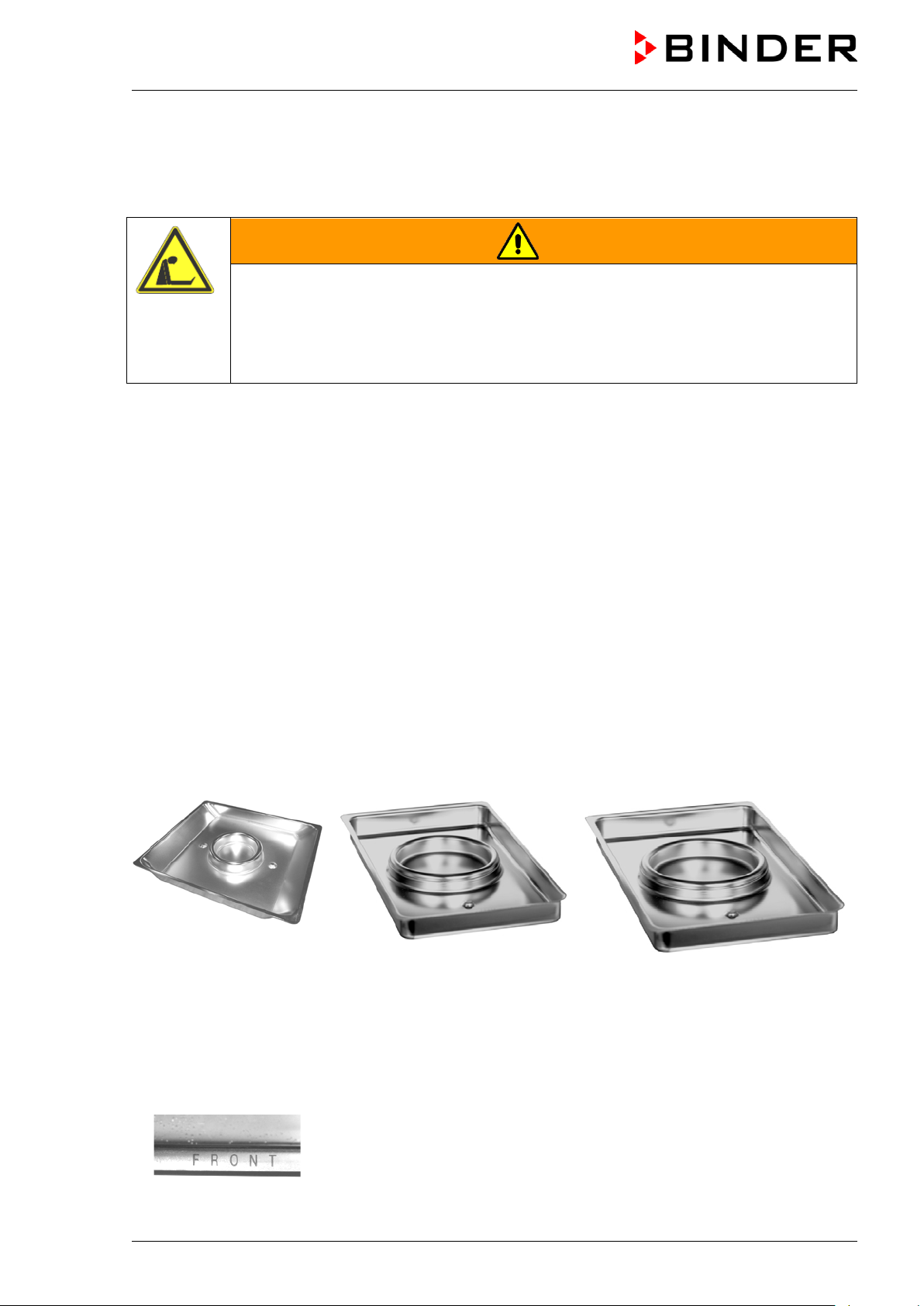
Chamber with O
Nitrogen (N
therefore practically imperceptible. Any N
control: Notes on handling nitrogen (N2)
2
) in high concentrations is hazardous to health. It is colorless and almost odorless and
2
gas that may escape must be safely led out via good room
2
ventilation or a suitable connection to an exhaust system.
WARNING
High concentration of N2.
Risk of death by suffocation.
∅ Do NOT set up chambers in non-ventilated recesses.
Ensure technical ventilation measures.
Observe the relevant regulations for handling N
.
2
4. Installation and connections
4.1 Shelves
You can put the shelves in different positions at the line of channel beads in the inner chamber. Hold the
shelf straight and then insert it so it will go smoot hly inside the chamber.
Permitted shelf loads:
Maximum load of one single shelf: 10 kg / 22 lb
Maximum total load of all shelves: 30 kg / 66 lb
4.2 Permadry™ water pan
The Permadry™ system developed by BINDER is an effective and easy to handle system that ensures
high humidity inside the chamber without any condensation forming on the inner surfaces. The
Permadry™ water pan consists of two pans in which the outer one is heated and the inner one cooled.
With the slight difference of temperature caused by that cooling, the central pan is the specific point for
condensation of the surplus humidity. Therefo re, all other inner surfaces remain dry.
CB 56 CB 170 CB 260
Figure 8: Permadry™ water pan
• Put the Permadry™ water pan on the bottom of the inner chamber in a way that both notches lock into
place.
• The front side of the CB 170 / CB 220 Permadry™ water pan is marked “FRONT”.
Figure 9: Letters “FRONT” indicating the front of the CB 170 / CB 220
Permadry™ water pan
CB (E7) 06/2018 Page 28/174
Page 29
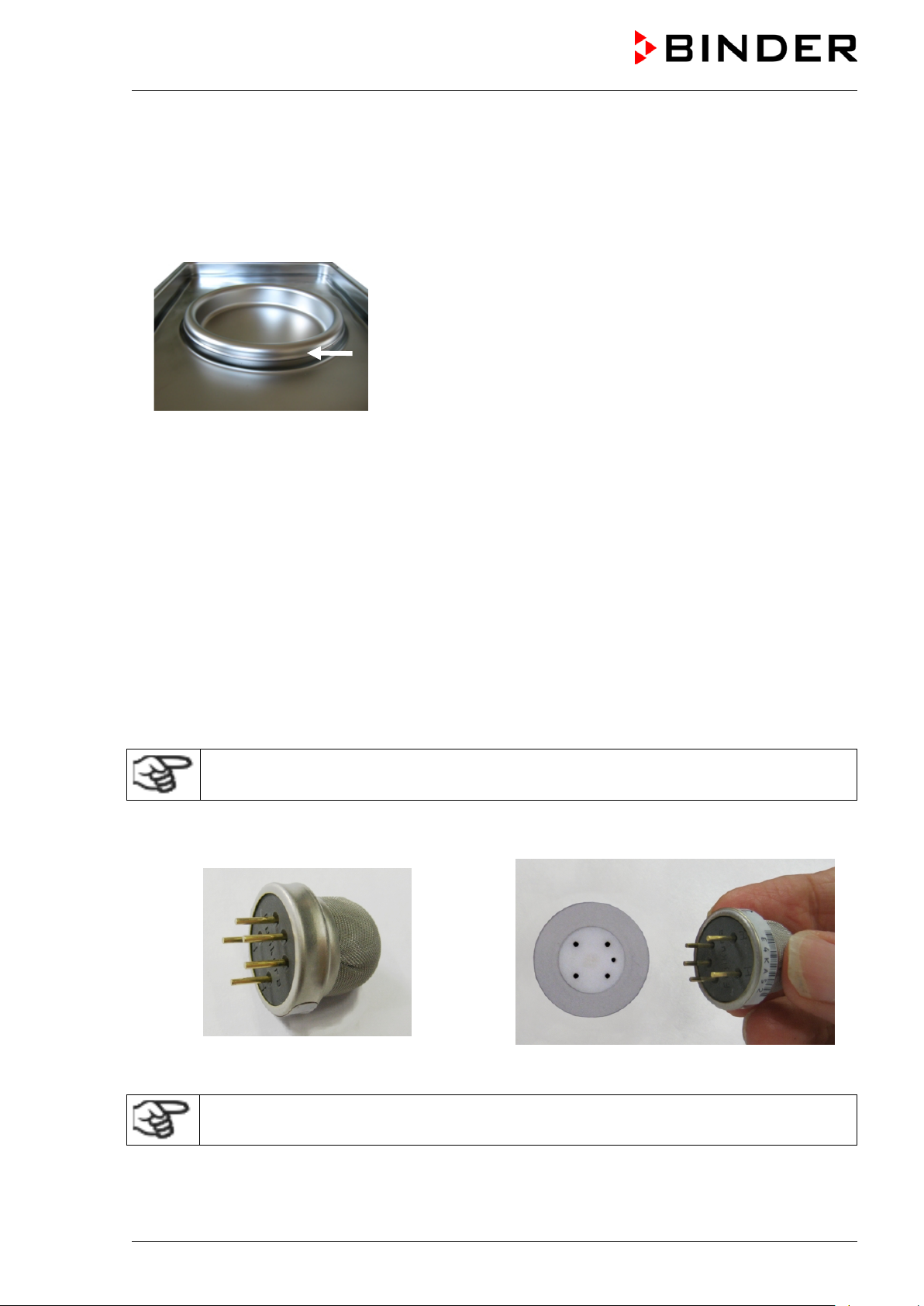
• Please make sure that the Permadry™ water pan has firm contact to the inner chamber bottom and
rests tightly on it (notches locked into place).
• Fill only the outer pan with distilled, sterilized water up to the filling level marking on the edge of the
inner pan.
Maximum filling quantity of the outer pan: CB 56: approx. 0.7 liters, CB 170: approx. 1.3 liters, CB 260:
approx. 2.0 liters.
Figure 10: Filling height line of the outer basin CB 170 / CB 220
• We recommend cleaning and refilling the pans 2 to 3 times a week. For evacuation, remove the
Permadry™ water pan.
• We recommend using distilled, sterile water to achieve optimum growth results. Any corrosive damage
that may arise following the use of water of different quality or by additives is excluded from the liability
agreement.
• If required, you can add microbiologically inhibiting substances such as copper chips, copper sulfate
or ethylene diamine tetra-vinegar acid (EDTA) in a concentration of 1 to 5 mmol/l.
Empty the Permadry™ water pan before moving the chamber. In case of the contents spilling,
immediately shut down the chamber and dry it carefully and compl etely.
4.3 Connecting the O2 sensor (chamber with O2 control)
The O2 sensor is supplied with the chamber in a separate package.
Connect or remove the O2 sensor only when the chamber is turned off.
Open the door of the inner chamber and plug the O2 sensor (F) into the left connection socket located in
the upper part of the rear of the inner chamber. P ay attention to the correct positioning of the pins.
Figure 11: O2 sensor Figure 12: Connecting the O2 sensor
The O2 sensor must be plugged in during a hot-air sterilization.
CB (E7) 06/2018 Page 29/174
Page 30
ew on the cap when not in
4.4 Gas connections
General information for safe handling of gas cy l i nders:
• Store and use gas cylinders only in well ventilated areas.
• Open the gas cylinder valve slowly to av oi d pressure surges.
• Secure gas cylinders during storage and use against falling (chaining).
• Transport gas cylinders with a cylinder cart, do not carry, roll, or throw them.
• Always close the valve even with apparently empty cylinders; scr
use. Return gas cylinders with the valve closed.
• Do not open gas cylinders by force. Mark them when damaged.
• Protect gas cylinders against fire, e.g. do not store together with flammable liquids.
• Observe relevant regulations for dealing with gas cylinders.
Secure the gas cylinder against falling and other m echanical damage.
WARNING
Safety valve tearing off.
Sudden release of the stored pressure energy.
Risk of injury.
Secure gas cylinders against falling (chaining).
Transport gas cylinders with a cylinder cart.
The valve of the gas cylinder always must be clo sed before screwing on or unscrewing the gas hose.
WARNING
Opening the cylinder valve when the cylinder is not connected.
Sudden release of the stored pressure energy.
Risk of injury.
Close the gas cylinder valve before connecting or removing the gas hose.
After connecting the gas cylinder, check all gas connections for leaks (e.g. with leak spray or
diluted soap solution).
CB (E7) 06/2018 Page 30/174
Page 31

4.4.1 Connection of the CO2 gas cylinder
Carbon dioxide (CO2) in high concentrations is hazardous to health. It is colorless and almost odorless
and therefore practically imperceptible. Vent out any CO
or a suitable connection to an exhaust system. We recommend inst al l ing a CO
High concentration of CO2 (> 4 Vol.-%).
Risk of death by suffocation.
Danger of poisoning.
∅ Do NOT set up chambers in non-ventilated recesses.
Ensure technical ventilation measures.
Observe the relevant regulations for handling CO
The CO2 gas necessary for operation must have a t echnical grade of 99.5 %.
The gas connections must be established by quali fied personnel who are trained in handling
the respective gases and familiar with the required safety measures.
gas that may escape via good room ventilation
2
warning system.
2
WARNING
.
2
The following steps are required:
Ensuring the correct CO
output pressure
2
A gas supply pressure above 2.5 bar / 36 psi will result in chamber damage.
Use a pressure reducer and make sure to avoid any excessive outlet pressure when connecting the
gas hose to the chamber.
The real outlet pressure of gas cylinders, sets of gas cylinders or central gas supplies am on the
second manometer must not exceed 2.5 bar / 36 psi.
CAUTION
Excessive outlet pressure > 2.5 bar / 36 psi.
Damage to the chamber.
∅ The outlet pressure must NOT exceed the indicated value of 2.5 bar / 36 psi.
Before connecting, check the outlet pressure on the pressure reducer of the
cylinder.
Adjust the outlet pressure to 2.0 bar / 29 psi above the ambient pressure.
Observe the correct outlet pressure also when replacing t he gas cylinders.
Establishing the connection to the chamber
Connect the supplied gas hose (internal diameter 6 mm / 0.24 inches) to the pressure reducer of the
gas cylinders or central gas supply and secure the connection with the supplied hose clamp.
Connect the pre-assembled hose nozzle of the gas hose to the quick acting closure socket (10) DN 6
on the chamber rear, as described in chap. 4.4.4.
Leak test
After connecting the gas cylinder, check all gas connections for leaks (e.g. with leak spray or diluted
soap solution).
CB (E7) 06/2018 Page 31/174
Page 32

cylinder or disconnect the gas supply (by pulling off the gas hose)
The recovery times of the gas concentrations inside the chamber after opening the door are
indicated in the technical data (chap. 25.4) and refer to a connecti on pressure of 2.0 bar / 29
psi. Decreasing supply pressure will result i n l onger recovery times.
Conversion table for gas inlet pressures, bar – psi, see chap. 25.8.
4.4.2 Connection of the O2 gas cylinder (chamber with O2 control with optional
alternative control range 10 up to 95 vol.-% O
Note: Do not connect the O2
when operating at setpoints below 19 vol.-% O2.
Oxygen (O2) is colorless and almost odorless and therefore practically imperceptible. It promotes burns,
which can proceed explosively. There is a fire hazard for flammable oxygenated materials, e.g. clothes
and hair. O
is heavier than air and may accumulate in low-lyin g areas.
2
)
2
WARNUNG
High concentration of O2 (> 21 % O2).
Fire and explosion hazard through contact of combustible materials with O
Risk of burns and other injuries.
∅ Do NOT set up chambers in non-ventilated recesses.
Ensure technical ventilation measures.
Observe the relevant regulations for handling O
.
2
The O2 gas necessary for operation must have a t echnical grade of 99.5 %.
.
2
The gas connections must be established by quali fied personnel who are trained in handling
the respective gases and familiar with the required safety measures.
The following steps are required:
Ensuring the correct O
output pressure
2
A gas supply pressure above 2.5 bar / 36 psi will result in chamber damage.
Use a pressure reducer and make sure to avoid any excessive outlet pressure when connecting the
gas hose to the chamber.
The real outlet pressure of gas cylinders, sets of gas cylinders or central gas supplies am on the
second manometer must not exceed 2.5 bar / 36 psi.
CAUTION
Excessive outlet pressure > 2.5 bar / 36 psi.
Damage to the chamber.
∅ The outlet pressure must NOT exceed the indicated value of 2.5 bar / 36 psi.
Before connecting, check the outlet pressure on the pressure reducer of the
cylinder.
Adjust the outlet pressure to 2.0 bar / 29 psi above the ambient pressure.
Observe the correct outlet pressure also when replacing t he gas cylinders.
CB (E7) 06/2018 Page 32/174
Page 33

Establishing the connection to the chamber
Connect the supplied gas hose (internal diameter 6 mm / 0.24 inches) to the pressure reducer of the
gas cylinders or central gas supply and secure the connection with the supplied hose clamp.
Connect the pre-assembled hose nozzle of the gas hose to the quick acting closure socket (11) DN 6
on the chamber rear, as described in chap. 4.4.4.
Leak test
After connecting the gas cylinder, check all gas connections for leaks (e.g. with leak spray or diluted
soap solution).
The recovery times of the gas concentrations inside the chamber after opening the door are
indicated in the technical data (chap. 25.4) and refer to a connecti on pressure of 2.0 bar / 29
psi. Decreasing supply pressure will result i n longer r ecove ry times.
Conversion table for gas inlet pressures, bar – psi, see chap. 25.8.
4.4.3 Connection of the N2 gas cylinder (chamber with O2 control)
Nitrogen (N2) in high concentrations is hazardous to health. It is colorless and almost odorless and
therefore practically imperceptible. Any N
ventilation or a suitable connection to an exhaust system.
gas that may escape must be safely led out via good room
2
WARNING
High concentration of N2.
Risk of death by suffocation.
∅ Do NOT set up chambers in non-ventilated recesses.
Ensure technical ventilation measures.
Observe the relevant regulations for handling N
The N2 gas necessary for operation must have a t echnical grade of 99.5 %.
The gas connections must be established by quali fied personnel who are trained in handling
the respective gases and familiar with the required safety measures.
The following steps are required:
Ensuring the correct N
output pressure
2
A gas supply pressure above 2.5 bar / 36 psi will result in chamber damage.
Use a pressure reducer and make sure to avoid any excessive outlet pressure when connecting the
gas hose to the chamber.
The real outlet pressure of gas cylinders, sets of gas cylinders or central gas supplies am on the
second manometer must not exceed 2.5 bar / 36 psi.
.
2
CB (E7) 06/2018 Page 33/174
Page 34

CAUTION
Excessive outlet pressure > 2.5 bar / 36 psi.
Damage to the chamber.
∅ The outlet pressure must NOT exceed the indicated value of 2.5 bar / 36 psi.
Before connecting, check the outlet pressure on the pressure reducer of the
cylinder.
Adjust the outlet pressure to 2.0 bar / 29 psi above the ambient pressure.
Observe the correct outlet pressure also when repla cing the gas cylinders.
Establishing the connection to the chamber
Connect the supplied gas hose (internal diameter 6 mm / 0.24 inches) to the pressure reducer of the
gas cylinders or central gas supply and secure the connection with the supplied hose clamp.
Connect the pre-assembled hose nozzle of the gas hose to the quick acting closure socket (9) DN 6
on the chamber rear, as described in chap. 4.4.4.
Leak test
After connecting the gas cylinder, check all gas connections for leaks (e.g. with leak spray or diluted
soap solution).
The recovery times of the gas concentrations inside the chamber after opening the door are
indicated in the technical data (chap. 25.4) and refer to a connecti on pressure of 2.0 bar / 29
psi. Decreasing supply pressure will result in longer recovery times.
Conversion table for gas inlet pressures, bar – psi, see chap. 25.8.
4.4.4 Connecting the gas hose to the chamber rear (for CO2, O2, N2)
The procedure of connecting the gas hose to the chamber rear is the same for any gas connection. All
quick acting closure sockets (CO
control range 10 up to 95 vol.-% O
Note for chambers with O
, N2 with O2 control, and O2 with O2 control and optional alternative
2
) are degreased and supplied with a FKM gasket.
2
control: The quick acting closure socket and the hose nozzle for the O2
2
connection must be degreased.
WARNING
Fire and explosion hazard through contact of fat with O2.
Risk of burns and other injuries.
∅ All connection parts for the O
The gas hose, which will be used to establish the connection to a gas cylinder, is already attached to the
hose nozzle and secured by a hose clamp. Plug the hose nozzle into the corresponding quick acting
closure socket (a) located at the rear of the chamber. This quick acting closure socket is closed by a
rubber cover (b).
connection must be degreased.
2
Only use the supplied hose nozzle to connect to t he qui ck acting closure socket.
Otherwise, the quick acting closure socket m ay leak, and/or it may become impossible to
connect the original hose nozzle. In this case, please contact BINDER Service.
CB (E7) 06/2018 Page 34/174
Page 35

Gas cylinder connection kits are available for CO2 ( Art. No. 8012-0014), O2
Pressure reducer with manometers for cylinder pressure (high pressure
assembled hose nozzle for quick acting
(a)
(c)
(b)
Remove the rubber cover (b) by pulling it of f.
Chamber rear
Figure 13: Connecting the hose lead to the gas cy l inder
Now fit the hose nozzle (c) in the quick acting closure socket. To remove the connection, pull the hose
nozzle off the quick acting closure socket.
4.4.5 Gas cylinder connection kits (option)
(Art. No. 8012-0015) and N2 (Art. No. 8012-0016).
The connection kit includes the following parts for connecting a gas cylinder
to the CO
•
gauge) and outlet pressure (low pressure gaug e)
• 5 m pressure hose with preclosure socket
• 1 hose clamp to connect the gas hose to the pressure reducer
Figure 14: Gas cylinder connection kit
Instructions 7001-0249 included with the connection kit describe connecting and setting the
gas cylinder connection kit.
incubator:
2
Excessive outlet pressure > 2.5 bar / 36 psi.
Damage to the chamber.
∅ The outlet pressure must NOT exceed the indicated value of 2.5 bar / 36 psi.
CB (E7) 06/2018 Page 35/174
Before connecting, check the outlet pressure on the pressure reducer of the cylinder.
Adjust the outlet pressure to 2.0 bar / 29 psi above the ambient pressure.
The gas connections must be established by quali fied personnel who are trained in handling
the respective gases and familiar with the required safety measures.
CAUTION
Page 36

CAUTION
4.5 Water supply for the chamber with active humidifi cation
Freshwater is supplied by manually filling the freshwater bag. It is not possible to connect the chamber
directly to a water pipe.
The freshwater bag has a volume of 0.9 liters / 0.32 cu.ft. and is placed behind the chamber door in a
recess.
To guarantee humidification during 24 hours ev en at high humidity set-points, we recommend
filling the freshwater bag daily at the end of the day .
When the freshwater can is empty, the message “Freshwater supply” will be displayed on the controller,
the buzzer sounds, and the humidification module turns off. After acknowledging the alarm, the
humidification module tries to fill up and st art operating.
Water consumption at 37 °C / 98.6 °F and 93 % r.h.:
• Without opening the door: very low.
• When opening the door 10 times a day: approx. 70 ml per day.
4.5.1 Types of suitable water quality
• Deionized water from a water treatment installation already existing at the customer's site.
Conductivity from 1 µS /cm up to a maximum of 20 µS/cm. (Water, which is in equilibrium with the CO
in the air, and has a conductivity below 1 µS/cm (ultrapure water), may cause acid corrosion due to its
low pH).
• Tap water that has been treated by the optional water treatment system BINDER Pure Aqua Service
(disposable system). A reusable measuring equipment to assess the water quality is included (chap.
4.5.3).
BINDER GmbH is NOT responsible for t he wat er quality at the user’s site.
Any problems and malfunctions that might arise foll owing use of water of deviating quality is
excluded from liability by BINDER GmbH.
The warranty becomes void in the event of use of water of deviating quality.
Calcification of the humidifying system.
Damage to the chamber.
Operate the chamber with deionized (demineralized) water only.
Water intake temperature NOT below +5 °C / 41 °F and not exceeding 40 °C / 104 °F.
2
CB (E7) 06/2018 Page 36/174
Page 37

4.5.2 Water supply installation
Please proceed in the following order:
1. Fill the freshwater bag with sterilized water.
Observe water quality and temperature (chap. 4.5.1).
As long as no tube is connected to the outlet of the freshwater bag, the bag outlet must be closed
2. Place the freshwater bag with the opening to the left in the recess behind the chamber door.
3. Establish the connection of the tube to the freshwater bag
4. Lead the tube along the pump
5. For operation with humidity, the f resh water bag outlet must be open
4.5.3 BINDER Pure Aqua Service (option)
The optional BINDER water treatment system (disposable system) is available to treat tap water. The
lifetime depends on water quality and the amount of treated water used. The measuring equipment to
assess the water quality is reusable.
For detailed information on operating the wat er treatment system BINDER Pure Aqua
Service and its function, please refer to the oper ating manual supplied with BINDER Pure
Aqua Service.
CB (E7) 06/2018 Page 37/174
Page 38

4.6 Electrical connection
The chambers are supplied ready for connection. They come with an IEC connec tor plug.
Model
CB 170
CB 170-UL
• The domestic socket must also provide a protective conductor. Make sure that the connection of the
protective conductor of the domestic installations to the chamber’s protective conductor meets the
latest technology. The protective conduc tors of the socket and plug must be compatible!
• Prior to connection and start-up, check the power supply voltage. Compare the values to the specified
data located on the chamber’s type plate (left chamber side, bottom right-hand, see chap. 1.4). We
recommend the use of a residual current cir cuit breaker.
• When connecting, please observe the regulations specified by the local electricity supply company as
well as the VDE directives (for Germany).
• Pollution degree (acc. to IEC 61010-1): 2
• Over-voltage category (acc. t o IEC 61010-1): II
Art. No.
(x = 0 or 1)
9x40- 0131
9x40- 0132
9x40- 0133
9x40- 0134
9x40- 0139
9x40- 0140
9x40- 0141
9x40- 0142
Power plug
Grounded plug
IEC 7/7
NEMA 5-20P 100-120 V (1N~) 50/60 Hz 16 A
Voltage
+/-10 %
200-230 V (1N~) 50/60 Hz 10 A
Power
frequency
Chamber
fuse
Danger of incorrect power supply voltage.
Damage to the equipment.
Check the power supply voltage before connect i on and start-up.
Compare the power supply voltage with the data indicated on the type plate.
See also electrical data (chap. 25.4).
To completely separate the chamber from the power supply, you must disconnect the power
plug. Install the chamber in a way that the power plug is easily accessible and can be easily
pulled in case of danger.
CAUTION
CB (E7) 06/2018 Page 38/174
Page 39

door, with elongated holes to
4.7 Handling and aligning the divided inner door, gas proof (optional
equipment)
Rubber profile gasket of
individual glass door of the
divided inner door
Hinge of the set-in divided inner
align the inner door
Measuring access port
Figure 15: Divided inner door, gas proof (exam pl e: CB 170)
• Pull the handles to open each of the individual glass doors. Do not press too hard while closing them
to avoid pushing the doors through the gasket i nto the inner chamber.
• The rubber profile gaskets of the individual glass doors are easy to replace.
• If the divided inner door is not in an aligned position, fasten the hinge screws in the elongated holes of
the hinge to align it. Align the door and operate the locking smoothly.
CB (E7) 06/2018 Page 39/174
Page 40

Operating mode
5. Functional overview of the MB2 chamber controller
The MB2 chamber controller controls foll owing parameters inside the chamber:
• Temperature in °C
• Carbon dioxide concentration in vol.-%
• Oxygen concentration in vol.-% (chamber with O
• Humidity in % r.h. (chamber with active humidification)
control)
2
Note: In this manual the chambers are described in the maximum equipment variant and
including the available options. Therefore, some of the pictured and described features a re
not available on every chambers
You can enter the desired set point values in fixed value operation mode directly on the display surface or
via the setpoint menu. For program operation the controller offers programming week and time programs.
In addition there is a timer program available (stopwatch function).
The controller offers various notifications and alarm messages with visual and audible indication and
remote alarms via e-mail, an event list (trace file) and the graphical display of the measuring values in the
in der chart recorder view. The MB2 program controller permits programming temperature and CO
/ O2
2
and humidity cycles, and specifying special controller functions for each program section. You can enter
values or programs directly at the controller or use the APT-COM™ 3 DataControlSystem software
(option) specially developed by BINDER.
Temperature values
values
CO
2
values (O2 control)
O
2
Humidity values (active
humidification)
Actual values
Set-point values
Functional icons
Figure 16: Normal display of the MB2 program controller (sample values, chamber with O
control and
2
active humidification)
CB (E7) 06/2018 Page 40/174
Page 41

Current operating mode
Date, time, authorization level
5.1 Operating functions in normal display
Text list for information icons
of the logged-in user, memory
Quick setpoint entry
Continue to next screen
Back to Normal display
Information
Program start
Setpoint entry
Event list
Display of active alarms
Access to main menu
Figure 17: Operating functions of the MB2 controller in normal display (sample values, chamber with O
control)
CB (E7) 06/2018 Page 41/174
2
Page 42

5.2 Display views: Normal display, program di splay, chart-recorder display
Press the Change view icon to toggle between normal display, program display and chartrecorder display.
Press the Normal display icon to return from program display and c hart recorder display back to
Normal display.
Normal display (actual values / setpoint values)
(Sample values, chamber with O
Program display (example: time program)
Chart recorder display
control and active humidification)
2
CB (E7) 06/2018 Page 42/174
Page 43

Icon
Signification
Function
Icon
Signification
Function
5.3 Controller icons overview
Navigation icons in Normal display
Main menu
Alarm
Event list
Access from Normal display to the main menu
Access from Normal display to the list of active alarms
Access from Normal display to the event list
Access from Normal display to the setpoint entry menu: setpoint
Setpoint setting
Program start
Program pause
Program cancelling
Information
Normal display
Change view
entry for Fixed value operation, turning on/off CO
humidity control, safety controller settings
Start a previously entered time or week program,
continue a paused time program
Pause a running time program
Cancel a running time or week program
Information on program operation, setpoints, actual values, and
the safety controller
Return from program display or chart recorder display to Normal
display
Toggle between Normal display, program display, and chart
recorder display
/ O2 and
2
Functional icons in individual menus
Back
Update
Confirm
Close
Reset alarm
Change keyboard
Edit
Return from each menu to Normal display
Update the event list and alarm messages
Take over the entries and exit the menu / continue menu
sequence.
Exit the menu / cancel menu sequence. Ent ries are not taken
over. When terminating a menu sequence, an inf ormation
window appears, which must be confirmed.
Acknowledge the alarm and mute the buzzer.
Change between uppercase and lower case characters, digits
and special characters
Edit settings of time and week programs
CB (E7) 06/2018 Page 43/174
Page 44

Icon
Signification
Function
Icon
Text information
Condition
Icon
Information
Functional icons in the chart recorder display
Show legend
Hide legend
Switch legend
Show indications
Hide indications
History display
Curve selection
Search
Zoom
Show scroll buttons
Hide scroll buttons
Show legend
Hide legend
Switch between legend pages
Show indication “Door open” (B2)
Hide indication “Door open” (B2)
Pause chart recorder and change to history display. Data recording
continues.
Go to “Curve selection” submenu in the history display
Go to “Search” submenu in the history display to select the required
instant
Go to “Zoom” submenu in the history display to select the zoom factor
Show scroll buttons in the history display to scroll to an instant
Hide scroll buttons in the history display to sc rol l to an instant
Information icons referring to chamber conditions
“Idle mode” Controller is in Idle mode
“Door open” Chamber door is open
“CO2 pressure alarm off” CO2 pressure alarm deactivated
“O2 pressure alarm off” O2 pressure alarm deactivated (chamber with O2 control)
“N2 pressure alarm off” N2 pressure alarm deactivated (chamber wit h O2 control)
“Interior socket” Interior socket (option) activated
Information icon for data processing
Waiting icon: Data processing is running.
Remaining time to touch the display when cali brating the touchscreen.
CB (E7) 06/2018 Page 44/174
Page 45

5.4 Operating modes
The MB2 program controller operates in the following operating modes:
• Idle mode
The controller is not functional, i.e., there is no heating, no CO
inlet or O2 inlet (O2 control) and no
2
humidification (active humidification). The chamber approximates ambient values.
You can activate and deactivate this operating mode with the “Idle mode” control contact in Fixed
value operating mode (chap. 7.3), time program operation (chap. 9.7.3) and week program operation
(chap. 10.6.5).
• Fixed value operating mode
The controller operates as a fixed-point controller, i.e., set-points for temperature, CO
, O2 (O2 control)
2
and humidity (active humidification) can be defined, which are then maintained until the next manual
change (chap. 7.1).
• Timer program operation
Stopwatch function: during an entered duration the controller constantly equilibrates to the setpoints
entered in Fixed value operation mode.
• Time program operation
An entered time program for temperature, CO
, O2 (O2 control) and humidity (active humidification) is
2
running. The controller offers 25 program memory places with 100 program sections each. The total
number of program sections of all programs is unl i m ited
• Week program operation
An entered week program for temperature, CO
, O2 (O2 control) and humidity (active humidification) is
2
running. The controller offers 5 program memory places with 100 switching points each. The switching
points can be distributed over all days of t he week.
CB (E7) 06/2018 Page 45/174
Page 46

5.5 Controller menu structure
Use the navigation icons in the screen footer in Normal display to access the desired controller
functions.
The available functions depend on the current authorization level “Service”, “Admin” or “User” (chap.
13.1). This is selected either during login or can be available without password protection.
Main menu: program settings, further information, “Service” submenu.
The “Settings” submenu allows general confi guration of the controller.
chap. 5.5.1
List of active alarms chap. 11
Access to the event list chap. 15.3
Setpoint entry for Fixed value operation, turning on/of f CO
control (chamber with O
humidification), safety controller settings
control) and humidity control (active
2
Start/ pause/ cancel an already entered, respectively a running time
program or start / cancel an already entered, res pectively a running
week program
control, O2
2
chap. 7, 6.8,
12.2
chap. 9.1,
9.2, 10.1
Unless noted otherwise, the figures show the functional range, which is available for the user with
“Admin” authorization level.
CB (E7) 06/2018 Page 46/174
Page 47

5.5.1 Main menu
The main menu provides access to the general configuration of the controller as well as to program entry
and the user administration. Additionally there are support functions like a contact page or the display
calibration depending on the available angle.
Press the Main menu icon to access the m ain m enu from Normal Display.
Press the Back icon to return from each setting menu to Normal Displ ay.
The main menu provides the following functions and submenus.
User management: login and logout,
password management
Chamber information chap. 15.2
“Settings” submenu (not visible for user with
“User” authorization level)
Program entry submenu for time and week
programs
“Service” submenu chap. 5.5.3
BINDER Service contact page chap. 15.1
Calibrating the touch screen chap. 14.4.2
Back to Normal Display
“Settings” submenu
• Settings of many general controller funct i ons and network settings (chap. 14).
chap. 13
chap. 14
chap. 9 and 10
• Available only for users wit h “S erv i ce” and “Admin” authorization level
“Service” submenu
• Access to service data, controller reset to factory settings (chap. 5.5.3)
• Available only for users with “Service” and “Admin” authorization level. Full functional range only for
BINDER Service (users with “Service” authorization level).
“Programs” submenu
• Access to the controller’s program functions (chap. 8, 9, 10)
CB (E7) 06/2018 Page 47/174
Page 48

language…
Setting the display brightness, continuous
operation and screen saver
Settings for the measurement chart: storage
maximum values
Configuration of the RS485 interface
Customized Solutions)
Entry of the MAC address and IP address
chap. 14.5.2
5.5.2 “Settings” submenu
The “Settings” submenu is available for users with “Service” or “Admin” authorization level. It serves to
enter date and time, select the language for the controller menus and the desired temperature unit and to
configure the controller’s communication functions.
Path: Main menu > Settings
5.5.3 “Service” submenu
Setting the temperature unit, menu
Setting date and time chap. 14.2
interval, storage values, minimum and
Setting the tolerance range and delay time for
tolerance range alarm
(available via BINDER INDIVIDUAL
Password protection for web server access chap. 14.5.3
Configuration of the e-mail server,
assignment of e-mail addresses
Back to main menu
chap. 14.1, 14.2
chap. 14.4
chap. 16.2
chap. 11.4
chap. 14.5.1
chap. 14.5.4
The “Service” submenu is available for users with “Service” or “Admin” authorization level. When loggedin with “Admin” authorization level the user will find information to tell the BINDER Service in service
case.
Path: Main menu > Service
Serial number of the chamber, setup version
of the controller software
No function
Information for BINDER Service
Reset to factory settings
Back to main menu
(view with “Admin” authorization level)
chap. 14.2
CB (E7) 06/2018 Page 48/174
Page 49

5.6 Principle of controller entries
In the selection and entry menus there are icons displayed in the footers which you can use to take over
the entry or cancel it.
Selection menu (example)
After completing the settings there are the f ol l owing possibilities:
Press the Confirm icon to take over the entries and exit the menu or continue the menu
sequence.
Press the Close icon to exit the menu or cancel the menu sequence wit hout taking over the
entries.
When terminating a menu sequence, an information window appears, which must be confirmed.
Entry menu (example)
5.7 Performance during and after power failures
During a power failure, all controller functions are shut down. The gas inlet valves are closed so that no
gas can escape into the ambient air. The zero-voltage relay alarm output (3) (chap. 11.6) is switched to
alarm position for the whole duration of the po wer f ai lure.
After the power returns, all functions retur n to the same status the chamber had before power failure. .
The controller continues to function in the original operating mode it was in previously before the power
failure occurred.
• Performance after power failure in Idle mode
Control is deactivated
• Performance after power failure in Fix ed value operation mode
All functions return to the same status the chamber had before power failure. The set-points are
immediately resumed.
• Performance after power failure during time program operation
The program is resumed at the point where the interruption occurred with the latest set-points reached
during the program run.
• Performance after power failure during week program operation
The week program continues with the values corresponding to the current time.
• Performance after power failure during sterilization operation
The sterilization process is cancelled and the controller changes to Fixed value operation mode with
the setpoints already entered. All setpoint values remain in memory.
CB (E7) 06/2018 Page 49/174
Page 50

Power failure and power return are noted in the event list (chap. 15.3).
If during power failure the inner chamber temperature or the CO
/ O2 concentration has fallen below the
2
alarm thresholds, confirm the alarms (e.g., tolerance range, safety controller). See chap. 11.3.
5.8 Performance when opening the door
When you open the door, CO2 control and O2 control (chamber with O2 control) immediately turns off.
After 60 seconds from opening the door, the heating and humidification (chamber with active
humidification) turn off.
After closing the door, heating, CO
control, O2 control (chamber with O2 control), humidification (chamber
2
with active humidification) turn on again.
6. Start up
6.1 Turning on the chamber
After connecting the supply lines (chap. 4), turn on the chamber by its main power switch. The lit pilot
lamp shows the chamber is ready for operation.
When the main power switch is turned on and yet the controller display is dark, the display is in stand-by
mode. Press on the touchscreen to activate it.
Check that the CO
control is activated (chap. 6.8).
2
Chamber with active humidification:
Fill the freshwater bag (chap. 4.5). Check that the humidifying system is activated (chap. 6.8).
After the first turning on of the chamber or after an interruption of the power supply the relative
humidity will increase after a delay of about 20 minutes. During this period, the relative humidity can
drop considerably.
Chamber with O
Check that the O
control:
2
control is activated (chap. 6.8).
2
Warming chambers may release odors in the first few days after commissioning. This is not a quality
defect. To reduce odors quickly we recommend heating up the chamber to its nominal temperature for
one day and in a well-ventilated location.
WARNING: If customer should use a BINDER chamber running in non-supervised
continuous operation, we strongly recomm end in case of inclusion of irrecoverable specimen
or samples to split such specimen or samples a nd store them in at least two chambers, if this
is feasible.
CB (E7) 06/2018 Page 50/174
Page 51

6.2 Controller settings upon start up
The window „Language selection“ enables the language selection, in case that it’s activated in the
“Start-up” menu. Afterwards occurs a request of the time zone and the temperature unit.
The controller will function in the operating mode, which was active before the last shut-down. It controls
temperature, CO
value operating mode to the last entered values and in the program mode to the set points achieved
beforehand.
, O2 (chamber with O2 control) and humidity (chamber with active humidification) in fixed
2
Locked operation
Provided that the user administration has been activated by the assignment of passwords for the different
authorization types, the controller operation is first locked after turning on the unit, recognizable by the
closed lock icon in the header.
In the locked view the controller provides all di splay functions. No setting functions are available.
The setpoints are shaded (light grey) in normal display. Changing them by direct entry in the fixed value
operating mode is not possible. The functional icons for setpoint entry and program start in the footer are
without function.
After turning on the unit, user log-in is required to operate the controller (chap. 13.2)
Operation without user log-in / without password-protection
If the password function has been deactivated, after turning on the unit without user log-in there are those
controller functions available, which correspond to the highest authorization level without a password
protection. There is no lock icon in the header.
CB (E7) 06/2018 Page 51/174
Page 52

6.3 Entering the altitude of the installation site
After first turning on the chamber, it is required to enter the altitude above sea level of the installation site
into the controller. This entry serves to correct the calculation of CO
measurement of partial pressure. The setti ng wil l rem ain stored after shutting the power off.
Path: Main menu > Settings > Various
concentration in vol.-% from the
2
Submenu “Various”.
Select the field “Altitude”
“Altitude” entry menu. Enter the desired altitude
above sea level in meters and confirm entry with
Confirm icon.
Factory setting: 650 m
6.4 Factory settings
The chamber is supplied with the following basic preset parameters:
• Temperature setpoi nt 37 °C / 98.6 °F
• CO
• O
• Humidity setpoint (chamber with active humidification) 93 % r.h.
• Safety controller class 3.1 Offset 2 °C
• Sterilization temperature 187.5 °C / 369.5 °F
• Audible alarm signal (buzzer) activated
• Altitude above sea level 650 m
setpoint 5 vol.-%
2
setpoint (chamber with O2 control) 21 vol.-%
2
The set temperature determines the target working temperature in the inner chamber, i.e. set value 37 °C
/ 98.6°F = target working temperature 37 °C / 98.6°F. The same is valid for the CO
(chamber with O
control) and humidity (chamber with active humidification). For the hot-air sterilization,
2
and O2 concentration
2
the set value is 187.5 °C / 369.5°F and cannot be c hanged.
As long as there is a difference between the actual and set value shown in the display,
adequate operation of the chamber is not guara nteed.
CB (E7) 06/2018 Page 52/174
Page 53

6.5 Equilibration time
Temperature
• Equilibration time is max. 4 hours.
CO
2
• After turning in the chamber, after approx. 5 minutes the CO
to the pre-set value of 5 vol.-% CO
.
2
• Equilibration time is max. 0.5 hours.
O
(chamber with O2 control)
2
• After turning in the chamber, the ambient oxygen concentration of approx. 20.9 vol.-% is displayed
after a delay of 10 minutes. During the first 10 minutes, O
to the displayed setpoint value of 21 vol.-%.
concentration equilibrates automatically
2
control is not defined. Then O2 is regulated
2
• For high O
setpoint values (with alternative control range option), equilibration time is max. 1.5 hours.
2
Humidity (without active humidification)
®
• With humidity control effected via the Permadry
system equilibration time is max. 15 hours
Humidity (chamber with active humidification)
• Equilibration time is max. 1 hour.
6.6 Operating the DuoDoor™ door lock
The DuoDoor™ door lock offers two different ways to open the doors, dependent on the glass door lock
position.
Opening outer door and glass door independently
When closing the glass door, close the glass do or l ock.
Then you can close and open the outer door using i ts handle.
The glass door will remain closed until you manu all y open the
glass door lock.
Figure 18: Closed position
Opening outer door and glass together
When closing the glass door leave the glass doo r l ock in open
position. Then close the outer door. The glass door is pressed
against the gasket so that both doors are se cur el y closed.
When opening the outer door, a magnetic device also opens the
glass door.
Figure 19: Open position
CB (E7) 06/2018 Page 53/174
Page 54

6.7 Required gas supply for the chamber with O2 control
In the chamber with O2 control, cell growth can be additionally influenced by a variable oxygen content.
Depending on the required range of O
end, two equipment variants are available:
6.7.1 Hypoxic control range 0.2 vol.-% up to 20 vol.- % O2 (regular)
In addition to the CO2 connection, the chamber provides a gas connection for N2.
concentration, the type of gas which is required may vary. To this
2
As compared to the ambient air (O
increased, no oxygen is required for the O
cylinder. Even with activated O2 control no O2 pressure alarm will be emitted.
an O
2
concentration of 20.9 vol.-%) only the N2 concentration needs to be
2
control. Therefore, it is not necessary and possible to connect
2
6.7.2 Alternative control range 10 vol.-% up to 95 vol.-% (option)
In addition to the CO2 connection, the chamber provides gas connections for O2 and N2.
• Operation in the hyperoxic range (> 22 vol.-% O
As compared to the ambient air (O
concentration of 20.9 vol.-%) only the O2 concentration needs to
2
be increased, no nitrogen is required for the O
)
2
control. Therefore, it is not necessary to connect a N2
2
cylinder.
You can deactivate the N
control no N
pressure alarm will be emitted.
2
pressure alarm in the controller (chap. 7.3). Then also with activated O2
2
• Alternating operation in the hyperoxic and hypoxic range or in the range from 20 vol.-% O
to 22 vol.-% O
and O2 are required for O2 control. It is necessary to connect all gas sup pl i es.
N
2
You can deactivate the O
activated O
2
and / or N2 pressure alarm in the controller (chap. 7.3). Then also with
2
control no O2 and / or N2 pressure alarm will be emitted.
2
6.7.3 Operation without O2 control
up
2
You can deactivate the O2 control in the controller (chap. 6.8). With this setting, no O2 and N2 pressure
alarms and no O
tolerance range alarm will be issued. The zero-voltage relay alarm contact (chap. 11.6)
2
will also not be triggered.
Since neither nitrogen nor oxygen are require d, it is not necessary to connect an O
or N2 cylinder.
2
CB (E7) 06/2018 Page 54/174
Page 55

6.8 Activating / deactivating CO2, O2 and humidity control
If CO2 control and/or O2 control (chamber with O2 control) and/or humidity control (chamber with active
humidification) shall not be used, it is possible to deactivate them in the controller.
Press the Setpoint setting icon to access the “Setpoint” set ting menu from Normal display.
“Setpoints” menu.
Select “Control on/off”.
You can turn on or off CO
control (chamber with O
control and O2
2
control) and humidity
2
control (active humidification)
Mark / unmark the checkbox to activate /
deactivate the desired function and press the
Confirm icon.
When operating the chamber with deactivated CO2 control, no CO2 pressure alarm and no
tolerance range alarm will be emitted.
CO
2
Chamber with O2 control: When operating the chamber with deactivated O2 control, no O2 and
pressure alarms and no O2 tolerance range alarm will be emitted.
N
2
Chamber with active humidification: When operating the chamber with deactivated humidit y
control no humidity tolerance range alarm will be em i tted. The controller continues to show the
actual humidity value but no longer the humidity set-point.
When operating the chamber with deactivated humidity control, humidification can be realized using the
Permadry™ water pan (chap. 6.9).
CB (E7) 06/2018 Page 55/174
Page 56

6.9 Humidity control of the Permadry™ system
With the chamber with active humidificati on, humidity setting via the Permadry™ System is not required.
The Permadry™ system with its 2-pan water system guarantees a maximum humidity of up to 95 % r.H.
in the inner chamber, which remains condensation-free. This performance assumes an average ambient
temperature of 22 +/- 3 °C / 71.6 +/- 5.4 °F and a working temperature in the inner chamber of 37 °C /
98.6 °F.
You can increase or decrease humidity slightly via the heating of the water pan if required.
Humidity is infinitely adjustable in whole num bers from -5 (low) to +5 (high).
Factory setting: “0” (medium).
Setting:
Path: Main menu > Settings > Various
“Humidity control” entry menu. Enter the desired
Submenu “Various”.
Select the field “Humidity control”
If the ambient temperature deviates by more than +/- 5 °C from the values recommended by
the manufacturer, the conditions for maxi m um ai r humidity with condensation-free inner
chamber are no longer guaranteed. Contact B INDER Service for assistance.
humidity and confirm entry with Confirm icon.
CB (E7) 06/2018 Page 56/174
Page 57

7. Set-point entry in “Fixed value” oper ating mode
In Fixed value operating mode you can enter set-points for temperature, CO2 and O2 (chamber with O2
control) and humidity (chamber with active humidification), and the switching-state of up to 16 operation
lines.
All settings made in Fixed value operating mode remain valid until the next manual change. They are
saved also when turning off the chamber or in case of toggling to Idle Mode or Program Mode.
Setting ranges Control ranges
Temperature
Temperature (chamber with
O2 control)
CO2
O2 (chamber with O2 control,
with regular hypoxic control
range)
O2 (chamber with O2 control,
with optional alternative
control range)
Humidity (chamber with
active humidification)
With set-point type “Limit”, adapt the safety controller (chap. 12.2) always when you changed
the temperature set-point. Set the safety control ler set-point by approx. 2 °C above the
controller temperature set-point.
Recommended setting: Set-point type “Offset” with safety controller set-point 2 °C.
When setting a lower temperature setpoint, in order to save time, we recommend cooling
down the chamber by turning it off and opening both chamber doors.
When setting a lower CO
escape first. Open both chamber doors for this purpose. Observe the precautions when
working with gases (chap. 1.6).
20 °C / 68 °F up to 60 °C /
140 °F
4 °C / 7.2 °F above ambient temperature
up to 60 °C / 140 °F
6 °C / 10.8 °F above ambient temperature
up to 60 °C / 140 °F
0 vol.-% up to 20 vol.- % 0 vol.-% up to 20 vol.- %
0.2 vol.-% up to 21 vol.- % 0.2 vol.-% up to 20 vol.- %
5 vol.-% up to 95 vol.-% 10 vol.-% up to 95 vol.-%
60 % r.h. up to 93 % r.h. 60 % r.h. up to 93 % r.h.
, O2 or humidity setpoint, the gas or humidity must be able to
2
CB (E7) 06/2018 Page 57/174
Page 58

7.1 Set-point entry through the “Setpoints” menu
Press the Setpoint setting icon to access the “Setpoint” set ting menu from Normal display.
“Setpoints” menu.
Select “Fixed value operation setpoints” to acc ess the
individual parameters.
• Select the field “Temperature” and enter the desired temperature setpoint.
Setting range: 20 °C up to 60 °C. Confirm entry with Confirm icon.
• Select the field “CO2” and enter the desired CO
setpoint.
2
Setting range: 0 vol.-% up to 20 vol.-%.
Confirm entry with Confirm icon.
Chamber with O
• Select the field “O2” and enter the desired O
control:
2
setpoint.
2
Setting range with regular hypoxic control range: 0.2 vol.-% up t o 20 vol.-%.
Setting range with alternative control range: 5 vol.-% up to 95 vol.-%.
Confirm entry with Confirm icon.
Chamber with active humidification:
• Select the field “Humidity” and enter the desired humidity setpoint.
Setting range: 60 % r.h. up to 93 % r.h. Confirm entry with Confirm icon.
When entering a value outside the setting range, the message: “Value outside of limits! (M in:
xxx, Max: xxx)” appears (xxx is a wildcard for the l i m its of the respective parameter). Press the
Confirm icon and repeat the entry with a correct value.
After completing the settings, press the Confirm icon to take over the entries and exit the menu, or press
the Close icon to exit the menu without taking over the entries.
CB (E7) 06/2018 Page 58/174
Page 59

7.2 Direct setpoint entry via Normal di spl ay
Alternatively you can also enter the setpoints directly via Normal display.
Normal display. Select the setpoint you want
to change.
Example: “Temperature” entry menu. Enter the
desired setpoint and confirm entry with Confirm
icon.
CB (E7) 06/2018 Page 59/174
Page 60

7.3 Special controller functions via operation lines
Press the Setpoint setting icon to access the “Setpoint” set ting menu from Normal display.
You can define the switching state of up to 16 operation lines (control contacts). They are used to activate
/ deactivate special controller functions.
Chamber with O
required may vary (chap. 6.6). Therefore, the pressure alarms for O
individually with active O
control: Depending on the required range of O2 concentration, the type of gas which is
2
control.
2
and N2 can be deactivated
2
For chambers equipped with the optional interior socket (chap. 18.3) you can turn on and off the voltage
of the interior socket via the controller.
• Operation line “Idle mode” activates / deact i vates the operating mode “Idle mode”.
• Operation line “O2 pressure alarm off” activates / deactivates the O
pressure alarm (chamber with O2
2
control)
• Operation line “N2 pressure alarm off” activates / deactivates the N
pressure alarm (chamber with O2
2
control)
• Operation line “Interior socket” activates / deactivates interior socket (option, available via BINDER
INDIVIDUAL Customized Solutions)
The other operation lines are without function.
Use the “Setpoints” menu to configure the operation lines.
“Setpoints” menu.
Select the field “Functions on/off”.
“Functions on/off” entry menu (view with
chamber with O
control with optional interior
2
socket).
Mark / unmark the checkbox to activate /
deactivate the desired function and press the
Confirm icon
Activated operation line: switching status “1” (On)
Deactivated operation line: switching stat us “0” (Off)
The operation lines count from right to left.
Example:
Activated operation line “Idle mode” = 000000000000000
Deactivated operation line “Idle mode” = 000000000000000
1
0
CB (E7) 06/2018 Page 60/174
Page 61

7.4 Safety instructions for set t ing high gas concentrations
Notes on handling carbon dioxide (CO2)
Carbon dioxide (CO
and therefore practically imperceptible. Vent out any CO
or a suitable connection to an exhaust sy st em. We recommend installing a CO
High concentration of CO2 (> 4 Vol.-%).
) in high concentrations is hazardous to health. It is colorless and almost odorless
2
gas that may escape via good room ventilation
2
warning system.
2
WARNING
Danger of death by suffocation.
Danger of poisoning.
∅ Do NOT set up chambers in non-ventilated recesses.
Ensure technical ventilation measures.
Observe the relevant regulations for handling CO
.
2
If CO2 is released, leave the area und inform the security service or fire department.
Chamber with O
Oxygen (O
2
control: Notes on handling oxygen (O2)
2
) is colorless and almost odorless and therefore practically imperceptible. It promotes burns,
which can proceed explosively. There is a fire hazard for flammable oxygenated materials, e.g. clothes
and hair. O
is heavier than air and may accumulate in low-lying areas.
2
WARNING
High concentration of O2 (> 21 % O2).
Fire and explosion hazard through contact of combustible materials with O
.
2
Risk of burns and other injuries.
∅ Do NOT set up chambers in non-ventilated rece ss es
Ensure technical ventilation measures
Observe the relevant regulations for handling O
.
2
Take appropriate measures to prevent oxygen enrichment and fire and explosion hazards in areas where
oxygen enrichment is possible.
Observe the general information for safe handl ing of oxygen (chap. 1.6).
Chamber with O
Nitrogen (N
therefore practically imperceptible. Any N
control: Notes on handling nitrogen (N2)
2
) in high concentrations is hazardous to health. It is colorless and almost odorless and
2
gas that may escape must be safely led out via good room
2
ventilation or a suitable connection to an exhaust system.
WARNING
High concentration of N2.
Risk of death by suffocation.
∅ Do NOT set up chambers in non-ventilated recesses
Ensure technical ventilation measures
Observe the relevant regulations for handling N
.
2
CB (E7) 06/2018 Page 61/174
Page 62

8. Timer program: stopwatch function
During an entered duration the controller constantly equilibrates to the setpoints entered in Fixed value
operation mode (temperature, CO
humidification), configuration of the operation lines). This duration can be entered as a “Timer program”.
During the program runtime, any setpoint changes do not become effective; the controller equilibrates to
the values which were active during program sta rt.
8.1 Starting a timer program
In Normal display press the Program start icon to access the “Program start” menu.
, O2 (chamber with O2 control), humidity (chamber with active
2
“Program start” menu
• In the field “Program type” select “Timer program”.
• Select the field “Program duration” and enter the desired program duration. Press the Confirm icon.
• Select the field “Program start” and enter the desired start time of the program in the “Program start”
entry menu. Press the Confirm icon. The program delay time until program start begins.
Normal display.
Information on the bottom of the screen indicat es the
currently running program and the time already passed.
The grey bar shows how much time of the whole t i m e is
elapsed.
8.1.1 Performance during program delay time
During the configured program delay time until program start, the controller equilibrates to the current
setpoints of Fixed value operation mode. Modifications of these setpoints are possible but become
effective only after the timer program is finished. When the configured moment for program start is
reached, the program delay time ends and the program starts running. The controller equilibrates to the
values which had been active during program st art
CB (E7) 06/2018 Page 62/174
Page 63

8.2 Stopping a running timer program
8.2.1 Pausing a running timer program
Press the Program pause icon to interrupt the program.
The program is paused. The program runtime stops running down, the time display flashe s.
There are the following options:
Press the Program start icon to continue the program
Press the Cancelling icon to cancel the program
8.2.2 Cancelling a running timer program
Press the Program cancelling icon to cancel the program.
A confirmation prompt is displayed. Press the Confirm icon to confirm that the program shall really be
cancelled.
After confirming the message the controller changes to Fixed value operation mode. Temperature and
humidity will then equilibrate to the setpoint s of Fixed value operation mode.
8.3 Performance after the end of the program
After the end of the program the message “Device
changes to fixed value operation mode” appear s on the
screen.
Press the Confirm icon.
After confirming the message the controller changes to Fixed value operation mode. Temperature and
humidity will then equilibrate to the setpoint s of Fixed value operation mode.
CB (E7) 06/2018 Page 63/174
Page 64

9. Time programs
The MB2 program controller permits programming time programs with real-time reference. It offers 25
program memory positions with up to 100 program sections each.
For each program section you can enter set-points for temperature, CO
and humidity (chamber with active humidification), section duration, type of set-point transition (ramp or
step) and the tolerance ranges.
If the safety controller has been set to “limi t” mode, check the setting of the safety controller
when changing the temperature set-point, (cha p. 12.2).
Programming remains saved in case of a power f ai l ure or after turning off the unit.
Path: Main menu > Programs> Time program
, O2 (chamber with O2 control),
2
9.1 Starting an existing time program
In Normal display press the Program start icon to access the “Program start” menu.
“Program start” menu
• In the field “Program type” select the setting “Time program”.
• In the field “Program” select the desired program.
• Select the field “Program start” and enter the desired program start time in the “Program start” entry
menu. Press the Confirm icon. The program delay ti m e until program start begins.
The program end is adapted automatically dependi ng on the entered program duration.
After completing the settings, press the Confirm icon to take over the entries and exit the menu. The
program starts running.
If instead you press the Close icon to exit the menu without taking over the entries, the program will not
start.
Normal display. Information on the bottom of the
screen indicates the currently running program and the
time already passed. The grey bar shows how much
time of the whole time is elapsed. If program durat i on
has been set to infinite, the grey bar is not displayed.
CB (E7) 06/2018 Page 64/174
Page 65

9.1.1 Performance during program delay time
During the configured program delay time until program start, the controller equilibrates to the current
setpoints of Fixed value operation mode. Modifications of these setpoints are effective. When the
configured moment for program start is reached, the program delay time ends and the program starts
running.
9.2 Stopping a running time program
9.2.1 Pausing a running time program
Press the Program pause icon to interrupt the program. .
The program is paused. The program runtime stops running down, the time display flashes.
There are the following options:
Press the Program start icon to continue the program
Press the Cancelling icon to cancel the program
9.2.2 Cancelling a running time program
Press the Program cancelling icon to cancel the program.
A confirmation prompt is displayed. Press the Confirm icon to confirm that the program shall really be
cancelled.
After confirming the message, the controller changes to Fixed value operation mode. Temperature and
humidity will then equilibrate to the setpoint s of Fixed value operation mode.
9.3 Performance after the end of the program
After the end of the program the message
“Device changes to fixed value operation
mode” appears on the screen.
Press the Confirm icon.
As long as the message has not been confirmed, the setpoint of the last program section remains
effective. Program the last section as desired. If the heating, CO
control) and humidification (chamber with active humidification) shall turn off, activate operation line “Idle
mode” in the last program section.
control, O2 control (chamber with O2
2
After confirming the message the controller changes to Fixed value operation mode. The setpoints of
Fixed value operation mode are then equilibrated.
CB (E7) 06/2018 Page 65/174
Page 66

Select a program section to open the
9.4 Creating a new time program
Path: Main menu > Programs > Time program
“Time program” menu:
overview of the existing programs.
Select an empty program place.
Enter the program name and, if desired,
additional program information in the
corresponding fields.
Press the Confirm icon.
The program view opens (chap. 9.5).
9.5 Program editor: program management
Path: Main menu > Programs > Time program
“Time program” menu:
overview of the existing programs.
Select an existing program (example: program
3) or create a new program (chap. 9.4).
The program view opens.
Program view (example: program 1).
If a new program has been created, there is
just one program section.
There are the following options:
section editor (chap. 9.6)
CB (E7) 06/2018 Page 66/174
Press the Edit icon to open the program
editor
Page 67

Program editor: “Edit program” menu
Select the desired function and press the Confirm
icon.
The program editor offers following options:
• Change the program name
• Copy program
• Replace program: Replacing an new or an existing program with the copied program. This menu point
is visible only after a program has been copied.
• Delete program
• Create new section
To add a new section, select “Create new
section” and press the Confirm icon.
The program view opens.
9.5.1 Deleting a time program
Program view.
A new section is always added at the very
bottom (example: section 2).
Path: Main menu > Programs > Time program
In the “Time program” menu select the program to be deleted. The program view opens.
In the program view press the Edit icon to open the program editor
In the program editor select “Delete program” and press the Confirm icon.
CB (E7) 06/2018 Page 67/174
The program is deleted. The controller returns t o the program view.
Page 68

9.6 Section editor: section management
Path: Main menu > Programs > Time program
Select the desired program.
Program view.
Select the desired program section
(example: section 1)
Section view (example: section 1).
There are the following options:
Select a parameter to enter or modify the
according value (chap. 9.7)
Press the Edit icon to open the program
editor
Section editor: “Edit section” menu
Select the desired function and press the Confirm icon.
The section editor offers following options:
• Copy section
• Replace section: Replacing an existing section with the copied section. This menu point is visible only
after a section has been copied.
• Insert section: Adding the copied section. This menu point is visible only after a section has been
copied.
• Delete section
• Add new section
CB (E7) 06/2018 Page 68/174
Page 69

9.6.1 Add a new program section
Section editor: “Edit section” menu.
Select “Create new section” and press the
Confirm icon.
Then select whether to insert the new section
before or after the current section.
Press the Confirm icon. The new section opens.
9.6.2 Copy and insert or replace a program section
Program view.
Select the program section to be copied
(example: section 1)
Section view (example: section 1).
Press the Edit icon to open the section editor.
Section editor: “Edit section” menu
Select “Copy section” and press the Confirm
icon.
The current section (example: section 1) is
copied.
The controller returns to the section view.
CB (E7) 06/2018 Page 69/174
Section view (example: section 1).
Press the Close icon to change to the
program view, if you want to select another
section to be replaced or before or after
which the copied section shall be inserted…
Page 70

Program view.
Select the section to be replaced or before or
after which the copied section shall be
inserted (example: section 2) and press t he
Confirm icon.
or
Press the Edit icon to open the section editor
if you want the current section to be replaced
or the copied section to be inserted before or
after it
Section view (example: section 1).
Press the Edit icon to open the section editor
Select “Replace section” to replace the select ed section
with the copied section
or
Select “Insert section” to additionally add the copied
section.
In this case select whether to insert it before or after the
selected section.
Section editor: “Edit section” menu
Press the Confirm icon
9.6.3 Deleting a program section
In the program view select the program sectio n to be deleted. The section view opens.
In the section view press the Edit icon to open the sect i on editor
In the section editor select “Delete secti on” and press the Confirm icon.
The section is deleted. The controller returns to t he section view.
CB (E7) 06/2018 Page 70/174
Page 71

Section duration
Type of setpoint transition: ramp or step
Operation lines
Temperature setpoint
CO2 setpoint
O2 setpoint (chamber with O2 control)
9.7 Value entry for a program section
Path: Main menu > Programs > Time program
Select the desired program and section.
The section view gives access to all parameters of a program section. You can enter or modify the
values.
Program name and section number
Repeating one or several sections within a program
Temperature tolerance range: minimum and maximum
CO2 tolerance range: minimum and maxim um
O2 tolerance range: minimum and maximum
Humidity setpoint (chamber with active humidification)
Humidity tolerance range: minimum and maximum
The setting and control ranges for the individual parameters are the same as for “Fixed value” operating
mode (chap. 7).
9.7.1 Section duration
Section view (partial view).
Select the field “Duration” indicating the t i m e.
“Duration” entry menu.
Enter the desired section duration with the arrow keys
and press the Confirm icon.
Setting range: 0 up to 99 hours 59 min 59 sec.
CB (E7) 06/2018 Page 71/174
Page 72

9.7.2 Set-point ramp and set-point step
You can define the type of transitions for temperature, CO2 concentration, O2 concentration (chamber
with O
“Ramp” mode: Gradual set-points changes
The set-point of a given program section functions as the section’s start value. During the section’s
duration, each set-point gradually passes to the set-point of the subsequent program section. The actual
value follows the continually changing set-point.
If the last program section is in “ramp” mode and the setpoint shall change within this section, then you
must program an additional section (with the shortest possible section duration) to provide the target
value of the last program section. Otherwise, the setpoint would remain constant during the section’s
duration.
control) and humidity (chamber with active humidification) for each individual program section.
2
Programming in the “ramp” mode allows all kinds of temperature and CO
• Gradual changes of temperature and CO
/ O2 concentration and humidity
2
/ O2 and humidity transitions:
2
The setpoint changes its value gradually during the entered section duration. The actual value follows
the continually moving set-point at any time.
• Program sections with constant temperature and CO
/ O2 concentration and humidity
2
The setpoints (initial values) of two subsequent program sections are identical; so the temperature and
humidity remain constant during the entire duration of the first program section.
• Sudden changes of temperature and CO
Steps can be programmed in ramp mode as temperature / CO
/ O2 concentration and humidity
2
/ O2 / humidity changes (ramps) that
2
occur during a very short interval. If the duration of this transitional program section is very short
(minimum entry 1 sec), the temperature, CO
/ O2 or humidity change will proceed rapidly within the
2
minimum amount of time.
“Step” mode: Sudden set-points changes
The set-point of any program section functions as the section’s target value. At the start of the program
section, heating up, attaining the set gas concentration and humidification occur with the maximum speed
to reach the set-point values and then remain constant for the remaining section time. Therefore the setpoints remain constant for the section’s duration. These changes occur rapidly within the minimum
amount of time (minimum entry: 1 second).
Programming in the “step” mode allows only two kinds of temperature and humidity transitions:
• Programming gradual changes of temperature / CO
/ O2 / humidity (ramps) is impossible in the “step”
2
mode
• Program sections with constant temperature and hum idity
The setpoints (target values) of two subsequent program sections are identical; so the temperature
and humidity remain constant during the entire duration of the first program section.
• Sudden changes of temperature and humidit y
The entered setpoint of the section is reached as fast as possible and then held constant for the
remaining section duration.
CB (E7) 06/2018 Page 72/174
Page 73

W/°C
t/min.
0
38.0
38.5
39.0
39.5
40.0
30 60 90
120 150 180 210 240
37.0
37.5
------------1-------------------------
2------------------------3------------
4----------5------------
Duration
[hh:mm:ss]
Temperature
[°C]
CO2
[Vol.-%]
O2
[Vol.-%]
Humidity
[% rH]
Ramp or
1
01:00:00
37.5
xxxx
xxxx
xxxx
Step
2
01:00:00
37.5
xxxx
xxxx
xxxx
Ramp
3
01:00:00
39.0
xxxx
xxxx
xxxx
Step
4
00:00:10
39.5
xxxx
xxxx
xxxx
Step
5
01:00:00
39.5
xxxx
xxxx
xxxx
Step
Selecting the setting “Ramp” or “Step”
Section view (partial view).
In the field “Course” select the desired s etting
“Ramp” or “Step”.
“Ramp” and “Step” mode example (representation of a temperature course)
Corresponding program table
Section No.
Step
CB (E7) 06/2018 Page 73/174
Page 74

9.7.3 Special controller functions via operation lines
You can define the switching state of up to 16 operation lines (control contacts). They are used to activate
/ deactivate special controller functions.
Chamber with O
required may vary (chap. 6.6). Therefore, the pressure alarms for O
individually with active O
control: Depending on the required range of O2 concentration, the type of gas which is
2
and N2 can be deactivated
control.
2
2
For chambers equipped with the optional interior socket (chap. 18.3) you can turn on and off the voltage
of the interior socket via the controller.
• Operation line “Idle mode” activates / deact i vates the operating mode “Idle mode”.
• Operation line “O2 pressure alarm off” activates / deactivates the O
pressure alarm (chamber with O2
2
control)
• Operation line “N2 pressure alarm off” activates / deactivates the N
pressure alarm (chamber with O2
2
control)
• Operation line “Interior socket” activates / deactivates interior socket (option, available via BINDER
INDIVIDUAL Customized Solutions)
The other operation lines are without function.
Use the Section editor to configure the operation lines.
Section view.
Select the field “Functions on/off”.
“Functions on/off” entry menu (view with chamber
with O
control with optional interior socket).
2
Mark / unmark the checkbox of the desired
function to activate / deactivate it and press t he
Confirm icon.
The controller returns to the section view.
Activated operation line: switching status “1” (On)
Deactivated operation line: switching stat us “0” (Off)
The operation lines count from right to left.
Example:
Activated operation line “Idle mode” = 000000000000000
Deactivated operation line “Idle mode” = 000000000000000
1
0
CB (E7) 06/2018 Page 74/174
Page 75

9.7.4 Setpoint entry
• Select the field “Temperature” and ente r the desired temperature setpoint.
Setting range: 20 °C up to 60 °C.
Confirm entry with Confirm icon. The controller returns to the section view.
• Select the field “CO2” and enter the desi red CO
setpoint.
2
Setting range: 0 vol.-% up to 20 vol.-%.
Confirm entry with Confirm icon. The controller returns to the section view.
Chamber with O
• Select the field “O2” and enter the desired O
control:
2
setpoint.
2
Setting range with regular hypoxic control range: 0.2 vol.-% up t o 20 vol.-%.
Setting range with alternative control range: 5 vol.-% up to 95 vol.-%.
Confirm entry with Confirm icon. The controller returns to the section view.
Chamber with active humidification:
• Select the field “Humidity” and enter the desired humidity setpoint.
Setting range: 60% r.h. up to 93% r.h.
Confirm entry with Confirm icon. The controller returns to the section view.
9.7.5 Tolerance range
You can specify tolerance ranges for temperature, CO2 and O2 (chamber with O2 control) and humidity
(chamber with active humidification) for each program section with different values for the tolerance
minimum and maximum. When the actual value exceeds the given threshold, the program is interrupted.
This is indicated on the display (see below). When the actual temperature is situated again within the
entered tolerance limits, the program automatically continues. Therefore, the duration of the program may
be extended due to the programming of tolerances.
Programming of tolerances may extend program duration.
An entry of “-99999” for the tolerance minimum means “minus infinite” and an entry of “999999” for the
tolerance maximum means “plus infinite”. Entry of these values will never lead to program interruption.
The entry of “0” for the tolerance minimum and/or maximum deactivates the respective tolera nce function.
When requesting rapid value transitions, we recommend not programming tolerance values in order to
enable the maximum speed for heating-up and CO
/ O2 control, and humidification.
2
Section view, showing the temperature tolerance
band
CB (E7) 06/2018 Page 75/174
Page 76

• Select the field “Tolerance band min” and enter the desired lower tolerance band value. Setting range:
-99999 to 99999. Confirm entry with Confirm icon. The cont rol ler returns to the section view.
• Select the field “Tolerance band max” and enter the desired upper tolerance band value. Setting
range: -99999 to 99999. Confirm entry with Confirm icon. The controller returns to the section view.
Set the tolerance ranges for other parameters accordingly, if desired.
If one of the actual values (temperature, CO
, O2 , humidity) is outside the program tolerance range the
2
whole program course is interrupted. During this program interruption time the controller equilibrates to
the set-points of the current section.
The screen header indicates “Program pause (tolerance band)”. The program runtime indication flashes
and does not proceed any further.
When the temperature or CO
/ O2 or humidity values are back within the entered program tolerance
2
range, the program continues automatically.
9.7.6 Repeating one or several sections within a time program
You can repeat several subsequent sections together. It is not possible to define the start section the
same time also as the target section, therefore you cannot repeat a single individual section.
Enter the desired number of repetitions in the field „Number of repetitions“ and the number of the section
to start the repetition cycle with in the field “Start section for repetition” To have sections repeated
infinitely, enter the number of repetition s as “-1”.
The selected sections are repeated as many ti m es as selected. Then the program continues.
Section view, showing the repetition function
• Select the field “Number of repetitions” and enter the desired number of repetitions. Setting range: 1 to
99, and -1 for infinite. Confirm entry with Confirm icon. The controller returns to the section view.
• Select the field “Start section for repetition” and enter the section number, at which the repetition
should start. Setting range: 1 up to the section before the currently selected section. Confirm entry
with Confirm icon. The controller returns to the section view.
CB (E7) 06/2018 Page 76/174
Page 77

9.7.7 Saving the time program
Section view.
After the all desired values of the program
section have been configured, press the
Confirm icon to take over the programming.
The controller changes to the program view.
To save the programming it is absolutely required to press the Confirm icon. Otherwise all
settings will be lost! There is no confirmat ion prompt!
Program view.
Press the Confirm icon to take over the
programming.
The controller changes to the Normal display.
CB (E7) 06/2018 Page 77/174
Page 78

10. Week programs
The MB2 program controller permits programming week programs with real-time reference. It offers 5
week program places in total with up to 100 shift points for each week program.
Path: Main menu > Programs> Week program
10.1 Starting an existing week program
In Normal display press the Program start icon to access the “Program start” menu.
“Program start” menu.
• In the field “Program type” select the setting “Week program”.
• In the field “Program” select the desired program.
• There are no further settings available in the “Program start” menu for week programs, as they are
needed only for time programs.
After completing the settings, press the Confirm icon to take over the entries and exit the menu. The
program starts running.
If instead you press the Close icon to exit the menu without taking over the entries, the program will not
start.
After starting the week program, the previously entered week program setpoints are active and will be
equilibrated according to the current time.
Information on the bottom of the screen indicat es the
currently running program.
10.2 Cancelling a running week program
Press the Program cancelling icon to cancel the program.
A confirmation prompt is displayed. Press the Confirm icon to confirm that the program shall really be
cancelled.
After confirming the message the controller changes to Fixed value operation mode. Temperature and
humidity will then equilibrate to the setpoint s of Fixed value operation mode.
CB (E7) 06/2018 Page 78/174
Page 79

10.3 Creating a new week program
Path: Main menu > Programs > Week program
“Week program” menu:
overview of the existing programs.
Select an empty program place.
Enter the program name and, if desired,
additional program information in the
corresponding fields.
Select the set-point course “Ramp” or “Step”
(chap. 10.6.1).
Press the Confirm icon. The program view
opens.
Program view.
For the first section no weekday is specified.
Therefore the section is first marked in red and
cannot be saved.
CB (E7) 06/2018 Page 79/174
Page 80

If a new program has been created, there is
Select a program section to open the
10.4 Program editor: program management
Path: Main menu > Programs > Week program
“Week program” menu:
overview of the existing programs.
Select an existing program
(example: program 1).
Program view (example: program 1).
just one program section.
There are the following options:
section editor (chap. 10.4.1)
Press the Edit icon to open the program
editor
The program editor offers following options:
• Change program name. This menu also offers to configure the ramp / step mode setting (chap.
10.6.1).
• Copy program
• Replace program: Replacing an new or an existing program with the copied program. This menu point
is visible only after a section has been copied.
• Delete program
• Add new section
Program editor: “Edit program” menu.
Select the desired function and press the Confirm icon.
CB (E7) 06/2018 Page 80/174
Page 81

To add a new section, select “Create new
section” and press the Confirm icon.
The program view opens.
Program view.
With a new section no weekday is specified.
Therefore the section is first marked in red and
cannot be saved.
A new section is always added at the very bottom
(example: section 3). When the section start i s
specified the sections are automatically arranged in
the correct chronological order.
10.4.1 Deleting a week program
Path: Main menu > Programs > Week program
In the “Week program” menu select the program to be del eted. The program view opens.
In the program view press the Edit icon to open the program editor
In the program editor select “Delete program” and press the Confirm icon.
The program is deleted. The controller returns t o the program view.
CB (E7) 06/2018 Page 81/174
Page 82

10.5 Section editor: section management
Path: Main menu > Programs > Week program
Select the desired program.
Program view.
Select the desired program section
(example: section 1)
Section view (example: section 1).
There are the following options:
Select a parameter to enter or modify
the according value (chap. 10.6)
Press the Edit icon to open the program
editor
Section editor: “Edit section” menu
Select the desired function and press the Confirm icon.
The section editor offers following options:
• Copy section
• Replace section: Replacing an existing section with the copied section. This menu point is visible only
after a section has been copied.
• Insert section: Adding the copied section. This menu point is visible only after a section has been
copied.
• Delete section
• Create new section
CB (E7) 06/2018 Page 82/174
Page 83

10.5.1 Add a new program section
Section editor: “Edit section” menu.
Select “Create new section” and press the
Confirm icon.
Program view.
With a new section no weekday is specified.
Therefore the section is first marked in red and
cannot be saved.
A new section is always added at the very bottom
(example: section 3). When the section start i s
specified the sections are automatically arr anged in
the correct chronological order.
10.5.2 Copy and insert or replace a program section
Section editor: “Edit section” menu
Select “Copy section” and press the Confirm
icon.
The current section (example: section 1) is
copied.
The controller returns to the program view.
CB (E7) 06/2018 Page 83/174
Program view
Select the section to be replaced or before or
after which the copied section shall be
inserted (example: section 2).
Press the Confirm icon
The controller returns to the section editor
Page 84

Select “Replace section” to replace the selected
section with the copied section
or
Select “Insert section” to additionally add the copied
section.
Press the Confirm icon.
If you selected “Insert section” the sections are
automatically arranged in the correct chronological
order.
Section editor: “Edit section” menu
10.5.3 Deleting a program section
In the program view select the program sectio n to be deleted. The section view opens.
In the section view press the Edit icon to open the sect i on editor
In the section editor select “Delete secti on” and press the Confirm icon.
The section is deleted. The controller returns to t he section view.
10.6 Value entry for a program section
Path: Main menu > Programs > Week program
Select the desired program and section.
The setting and control ranges for the individual parameters are the same as for “Fixed value” operating
mode (chap. 7).
10.6.1 Set-point ramp and set-point step modes
The explanation of the settings “Ramp” or “Step” is given in chap. 9.7.2.
You can define the type of transitions for temperature, CO
with O
control) and humidity (chamber with active humidification) for the entire week program.
2
Select the desired program and press the Edit icon to open the program editor. In the program editor
select the “Change program name” function and press the Confirm icon.
concentration, O2 concentration (chamber
2
CB (E7) 06/2018 Page 84/174
Page 85

In the field “Weekday” select the desired weekday.
“Change program name” menu.
In the field “Course” select the desired s etting
“Ramp” or “Step” and press the Confirm icon.
10.6.2 Weekday
Section view.
10.6.3 Start time
With “Daily” selected, this section will run every day
at the same time.
Section view.
Select the field “Moment”.
CB (E7) 06/2018 Page 85/174
Entry menu “Moment”.
Select with the arrow keys the desired start
moment of the section and press the Confirm
icon.
Page 86

10.6.4 Setpoint entry
• Select the field “Temperature” and ente r the desired temperature setpoint.
Setting range: 20 °C up to 60 °C.
Confirm entry with Confirm icon. The controller returns to the section view.
• Select the field “CO2” and enter the desired C O
setpoint.
2
Setting range: 0 vol.-% up to 20 vol.-%.
Confirm entry with Confirm icon. The controller returns to the section view.
Chamber with O
• Select the field “O2” and enter the desired O
control:
2
setpoint.
2
Setting range with regular hypoxic control range: 0.2 vol.-% up to 20 v ol. -%.
Setting range with alternative control range: 5 vol.-% up to 95 vol.-%.
Confirm entry with Confirm icon. The controller returns to the section view.
Chamber with active humidification:
• Select the field “Humidity” and enter the desired humidity setpoint.
Setting range: 60% r.h. up to 93% r.h.
Confirm entry with Confirm icon. The controller returns to the section view.
10.6.5 Special controller functions via operation lines
You can define the switching state of up to 16 operation lines (control contacts). They are used to activate
/ deactivate special controller functions.
Chamber with O
required may vary (chap. 6.6). Therefore, the pressure alarms for O
individually with active O
For chambers equipped with the optional interior socket (chap. 18.3) you can turn on and off the voltage
of the interior socket via the controller.
control: Depending on the required range of O2 concentration, the type of gas which is
2
and N2 can be deactivated
control.
2
2
• Operation line “Idle mode” activates / deact i vates the operating mode “Idle mode”.
• Operation line “O2 pressure alarm off” activates / deactivates the O
pressure alarm (chamber with O2
2
control)
• Operation line “N2 pressure alarm off” activates / deactivates the N
pressure alarm (chamber with O2
2
control)
• Operation line “Interior socket” activates / deactivates interior socket (option, available via BINDER
INDIVIDUAL Customized Solutions)
The other operation lines are without function.
Select the desired program and section. You can set the operation lines in the “Functions on/off” field.
For details please refer to chap. 9.7.3.
CB (E7) 06/2018 Page 86/174
Page 87

Information
icon
Start after
condition occurred
11. Notification and alarm functions
11.1 Notification and alarm messages overview
11.1.1 Notifications
Notifications are indicated by information icons displayed in the screen header in Normal display
An information icon serves as an indication of a certain condition.
If this condition persists, in some cases an alarm will be triggered after a fix or configurable interval. As
long as the condition persists, the information icon therefore continues to be displayed also in state of
alarm. If during alarm the conditions ends, e.g., if during a tolerance range alarm the actual value returns
to within the tolerance range, the information icon disappears, whereas the alarm will continue until
manual acknowledgement.
Press the flash icon next to the information i con to access the corresponding text inf ormation.
Condition
The controller is in Idle mode (chap. 5.4).
Chamber door open
CO2 pressure alarm deactivated
Chamber with O2 control:
O
pressure alarm deactivated
2
Chamber with O2 control:
N
pressure alarm deactivated
2
Normal display showing the text information.
The currently valid information texts are
highlighted in black (example: “O2 pressure
alarm off“)
Text information
“Idle mode” immediately
“Door open” immediately
alarm off”
“O2 pressure alarm
“CO2 pressure
off”
“N2 pressure alarm
off”
immediately
immediately
immediately
Interior socket (option) activated
“Interior socket” immediately
Notifications are not shown in the event list.
CB (E7) 06/2018 Page 87/174
Page 88

Start after
condition occurred
Zero-voltage relay
alarm output
11.1.2 Alarm messages
Condition Alarm message
Having reached the setpoint, the
actual temperature value deviates by
more than the set tolerance range
value and longer than the set delay
time from the setpoint
or
the temperature doesn’t reach the
tolerance range within 3 hours from
turning on the chamber or closing the
door.
Having reached the setpoint, the
actual CO
concentration deviates by
2
more than the set tolerance range
value and longer than the set delay
time from the setpoint
or
the CO
concentration doesn’t reach
2
the tolerance range within 3 hours
from turning on the chamber or closing
the door
“Temperature
range”
“CO2 range”
After configurable
delay time (chap.
11.5). Factory
setting: 10 minutes
After configurable
delay time (chap.
11.5). Factory
setting: 10 minutes
With alarm start
With alarm start
Chamber with O2 control:
Having reached the setpoint, the
actual O
concentration deviates by
2
more than the set tolerance range
value and longer than the set delay
time from the setpoint
or
concentration doesn’t reach the
the O
2
tolerance range within 3 hours from
turning on the chamber or closing the
door
Chamber with active humidification:
Having reached the setpoint, the
actual humidity value deviates by
more than the set tolerance range
value and longer than the set delay
time from the setpoint
or
the humidity doesn’t reach the
tolerance range within 3 hours from
turning on the chamber or closing the
door.
Chamber door is open for longer than
the set delay time.
“O2 range”
“Humidity range”
“Door open”
After configurable
delay time (chap.
11.5). Factory
setting: 10 minutes
After configurable
delay time (chap.
11.5). Factory
setting: 10 minutes
After configurable
delay time (chap.
11.5). Factory
setting: 1 minute
With alarm start
With alarm start
----
Power failure --- ---- immediately
CB (E7) 06/2018 Page 88/174
Page 89

Start after
condition occurred
Zero-voltage relay
alarm output
Condition Alarm message
Exceeded setpoint of the safety
controller class 3.1
Low CO2 outlet pressure
(< 0.3 bar / 4.4 psi)
Chamber with O2 control:
Low O
outlet pressure
2
(< 0.3 bar / 4.4 psi)
Chamber with O2 control:
Low N
outlet pressure
2
(< 0.3 bar / 4.4 psi)
Temperature sensor defective
Safety controller temperature sensor
defective
CO2 sensor defective. Contact
BINDER Service.
Chamber with O2 control:
O
sensor defective. Contact BINDER
2
Service
Chamber with active humidification:
Humidity sensor defective. Contact
BINDER Service
“Safety controller immediately ----
“CO2 pressure” immediately ----
“O2 pressure” immediately ----
“N2 pressure” immediately ----
e.g. “- - - - “ or
“<-<-< “ or “>->->”
Safety controller
sensor
immediately immediately
immediately immediately
“CO2 sensor fault” immediately immediately
“O2 sensor fault” immediately immediately
“Humid sensor fault” immediately immediately
Hot air sterilization running “Sterilization” immediately ---Alarm messages are displayed in the list of active alarms until acknowledging them. They are also shown
in the event list.
When operating the chamber without CO
gas control in the “setpoints” menu (chap. 6.8) in order to avoid tolerance range and pressure
/ O2 / N2 connection, turn off the corresponding
2
alarms.
Chamber with active humidification: When operating the chamber without water supply, turn
off humidity control in the “setpoints” menu (chap. 6.8) in order to avoid humidity alarms..
CB (E7) 06/2018 Page 89/174
Page 90
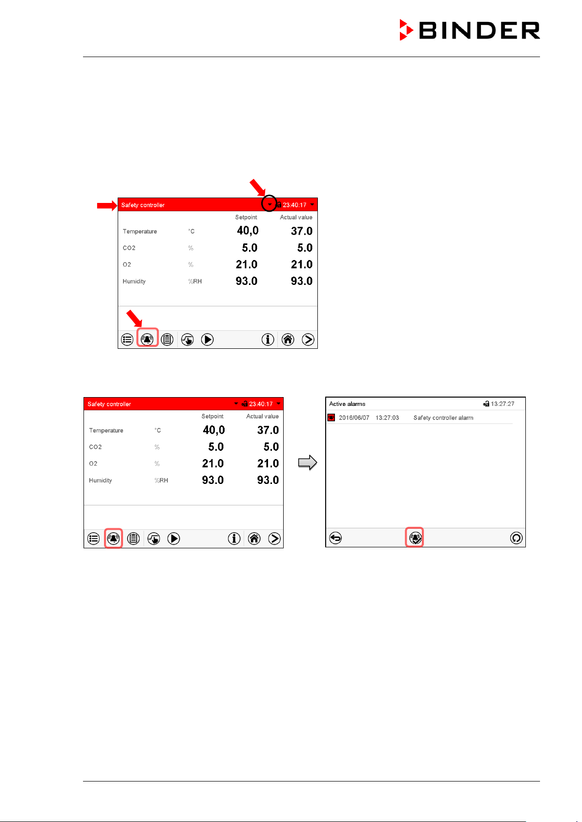
Screen header flashing in red color and
icon on the bottom of the screen:
change to the list of active alarms and
(a)
(c)
(b)
11.2 State of alarm
1. Visual indicati ons in Normal display: alarm message, screen header flashing in red color
2. Audible alert, if the buzzer is enabled (chap. 11.4).
3. In some cases: Switching the zero-voltage relay alarm output (chap. 11.6) to transmit the alarm e.g.,
to a central monitoring system.
Normal display in state of alarm (example).
(a)
showing the alarm message
(b) Alarm
alarm acknowledgement
(c) If applicable, information icon in the screen
header. Indication of a certain condition
11.3 Resetting an alarm, list of active alarms
Normal display in state of alarm (example).
Press the Alarm icon
Pressing the Reset alarm icon mutes the buz zer for all active alarms. The icon then disappears.
• Acknowledging while the alarm condition persists: Only the buzzer turns off. The visual alarm
indication remains on the controller display. The alarm remains in the list of active alarms.
List of active alarms.
Press the Reset alarm icon.
When the alarm condition has ended, the visual alarm indication is automatically cleared. The alarm is
then no longer in the list of active alarms.
• Acknowledging after the alarm condition has ended: The buzzer and the visual alarm indication are
reset together. The alarm is then no longer in the list of active alarms.
• The zero-voltage relay alarm output resets together with the alarm.
For appropriate actions in the event of an alarm, please refer to chap. 24 “Troubleshooting”.
CB (E7) 06/2018 Page 90/174
Page 91

11.4 Activating / deactivating the audible alarm (alarm buzzer)
Path: Main menu > Settings > Chamber
“Chamber” submenu (example).
In the field “Audible alarm” select the desired setting
“off“ or “on” and press the Confirm icon.
11.5 Tolerance range settings and alarm delay times
Path: Main menu > Settings > Various
Submenu “Various”.
Select the desired function.
In this menu you can set the deviation between the actual value and setpoint for temperature, CO
(chamber with O
control) and humidity (chamber with active humidification) which that shall cause a
2
tolerance range alarm, and you can define the delay time after which the tolerance alarm will be triggered.
Also you can set the delay time after opening the door will trigger an alarm.
The entered value defines the tolerance range around the setpoint value. Example: Temperature setpoint:
37 °C, tolerance range value: +/- 2 °C, i.e. this def i nes a tolerance range from 35 °C up to 39 °C.
, O2
2
Alarms following deviations from the tolerance range or door opening
If the actual value, after having reached the setpoint, deviates by more than the set tolerance range value
and longer than 10 min. from the setpoint or the temperature doesn’t reach the tolerance range within 3
hours from turning on the chamber or closing the door, after the configured interval (e.g., “Temp range
alarm delay”) an alarm is triggered. It is visually indicated in Normal display. If the alarm buzzer is
activated (chap. 11.4) there is an audible alert. The zero-voltage relay alarm output (chap. 11.6) switches
to transmit the alarm. The alarm is shown in the l ist of active alarms (chap. 11.3).
CB (E7) 06/2018 Page 91/174
Page 92

Alarm message
Start after condition occurred
“Temperature range” after configurable time
“CO2 range after configurable time
“O2 range after configurable time
“Humidity range after configurable time
“Door open” after configurable time
If the condition (deviation from the tolerance range or door opening) ends within the configured alarm
delay time, no alarm will be triggered after the delay time.
When operating the chamber with deactivated CO
(chamber with active humidification) control (chap. 6.8), the corresponding tolerance range
, O2 (chamber with O2 control) or humidity
2
alarms will not occur.
Setting:
• Select the field ”Temperature range” and enter the desired value for the temperature range. Setting
range: 1 °C to 10 °C. Confirm entry with Confirm icon.
• Select the field “Temp alarm delay” and enter the time in minutes, after which the range alarm shall be
triggered. Setting range: 1 min to 120 min. Confirm entry with Confirm icon.
• Select the field ”CO2 range” and enter the desired value for the CO
range. Setting range: 1 vol.-% to
2
10 vol.-%. Confirm entry with Confirm icon.
• Select the field “CO2 alarm delay” and enter the time in minutes, after which the range alarm shall be
triggered. Setting range: 1 min to 120 min. Confirm entry with Confirm icon.
• Select the field ”O2 range” and enter the desired value for the O
range. Setting range: 1 vol.-% to 10
2
vol.-%. Confirm entry with Confirm icon.
• Select the field “O2 alarm delay” and enter the time in minutes, after which the range alarm shall be
triggered. Setting range: 1 min to 120 min. Confirm entry with Confirm icon.
• Select the field “Humidity range” and enter the desired value for the humidity range. Setting range: 5%
r.h. to 20% r.h. Confirm entry with Confirm icon.
• Select the field “Humid alarm delay” and enter the time in minutes, after which the range alarm shall
be triggered. Setting range: 1 min to 120 min. Confirm entry with Confirm icon.
• Select the field “Door alarm delay” and enter the time in minutes, after which the range alarm shall be
triggered. Setting range: 1 min to 120 min. Confirm entry with Confirm icon.
After completing the settings, press the Confirm icon to take over the entries and exit the menu, or press
the Close icon to exit the menu without taking over the entries.
CB (E7) 06/2018 Page 92/174
Page 93

The chamber is equipped with a zero-voltage relay output which permits the
) on the chamber rear. A suitable DIN
) on the chamber rear
Alarm message
Condition
Switching the alarm contact
11.6 Zero-voltage relay alarm output
transmission of some alarm messages to a central monitoring system.
The connection is realized as a DIN socket (3
plug is enclosed.
Figure 20: Pin configuration of the DIN socket (3
ALARM
Pin 1: Pole, Pin 2: Break relay, Pin 3: Make contact
In case there is no alarm, contact 1 closes with cont act 3.
Closing contact 1 with contact 2 switches the ze ro-v oltage relay alarm output.
Maximum loading capacity of the switching contacts: 24V AC/DC – 2.5A
DANGER
Electrical hazard.
Danger of death.
Damage to switching contacts and conn ection socket.
∅ Do NOT exceed the maximum switching load of 24V AC/DC – 2.5A.
∅ Do NOT connect any devices wit h a higher loading capacity.
The zero-voltage relay alarm output switches at the following events:
---
“Temperature range”
“CO2 range”
Temperature tolerance range alarm
CO
Power failure immediately
After configurable delay time (chap.
(see chap. 11.1.2)
tolerance range alarm
2
(see chap. 11.1.2)
11.5). Factory setting: 10 minutes
After configurable delay time (chap.
11.5). Factory setting: 10 minutes
O
tolerance range alarm
“O2 range”
“Humidity range”
“Door open”
2
(chamber with O
control)
2
(see chap. 11.1.2)
Humidity tolerance range alarm
(chamber with active humidification)
(see chap. 11.1.2)
Chamber door open alarm
(see chap. 11.1.2)
After configurable delay time (chap.
11.5). Factory setting: 10 minutes
After configurable delay time (chap.
11.5). Factory setting: 10 minutes
After configurable delay time (chap.
11.5). Factory setting: 1 minutes
In case of a tolerance range alarm or a door open alarm, the alarm message on the controller display
remains on during the alarm transmission v i a the zero-voltage relay outputs.
As soon as the cause of the alarm is identified and resolved, you can reset the alarm transmission via the
zero-voltage relay outputs together with the alarm message in the “Active alarms” menu by pressing the
Reset alarm icon.
In case of a power failure, transmission of the alarm via zero-voltage relay outputs remains active for the
duration of the power failure. After power returns, contact 1 closes automatically with contact 3.
When using the communication software AP T-COM™ 3 DataControlSystem (option, chap.
18.1) for data acquisition, the alarm messages are only recorded in the protocol.
Set the tolerance limits for limit alarms by APT-COM™ 3 separately i n the APT-COM™ 3
measuring window.
CB (E7) 06/2018 Page 93/174
Page 94
12. Temperature safety devices
12.1 Over temperature protective device (class 1)
The chamber is equipped with an internal temperature safety device, class 1 acc. to DIN 12880:2007. It
serves to protect the chamber and prevents dangerous conditions caused by major defects.
If the actual temperature exceeds the nominal temperature by approx. 10 °C, the over temperature
protective device permanently turns off the chamber. The user cannot restart the device again. The
protective cut-off device is located internally. Only a service specialist can replace it. Therefore, please
contact an authorized service provider or B INDER Service.
12.2 Overtemperature safety controller class 3.1
The chambers are regularly equipped with an electronic overtemperature safety controller (temperature
safety device class 3.1 according to DIN 12880:2007). The safety controller is functionally and electrically
independent of the temperature control system. If an error occurs, it performs a regulatory functi on.
Please observe the DGUV guidelines 213-850 on safe working in laboratories (formerly BGI/GUV-I 850-0,
BGR/GUV-R 120 or ZH 1/119, issued by the employers’ liability insurance association) (for Germany).
The overtemperature safety controller serves to protect the chamber, its environment and the contents
from exceeding the maximum permissible temperature. In the case of an error, it limits the temperature
inside the chamber to the entered safety controller set-point. This condition (state of alarm) is indicated
visually and additionally with an audible alert if the buzzer is enabled (chap. 11.4). The alarm persists until
the chamber cools down below the configured safety controller setpoint.
Check the setting regularly and adjust it f ol lowing changes of the set-point or charge.
The safety controller only activates after the set-point has been reached once.
During a running sterilization (chap. 21.3) the safet y controller is non-functional
CB (E7) 06/2018 Page 94/174
Page 95

In the field “Mode” select the desired setting
12.2.1 Safety controller modes
You can select between “Limit (absolute)” and “Offset (relative)” safety controller mode
• Limit: Absolute maximum permitted temperature value
This setting offers high safety as a defined temperature limit will not be exceeded. It is important to
adapt the safety controller set-point after each modification of the temperature set-point. Otherwise,
the limit could be too high to ensure efficient protection, or, in the opposite case, it could prevent the
controller from reaching an entered set-point outside the limit range.
• Offset: Maximum overtemperature above any active temperature set point. The maximum
temperature changes internally and automatically with every set-point change.
This setting is recommended for program operation. It is important to check the safety controller set-
point and safety controller mode occasionally, as it does not offer a fix, independent limit temperature
value, which would never be exceeded.
Example: Desired temperature value: 37 °C, desired safety controller value: 39 °C.
Possible settings for this example:
Temperature set point Safety controller mode Safety controller set-point
37 °C
12.2.2 Setting the safety controller
Press the Setpoint setting icon to access the “Setpoint” set ting menu from Normal display.
Limit (absolute) 39 °C
Offset (relative) 2 °C
“Setpoints” menu.
Select the field “Safety controller” to access the
settings.
•
“Limit” or “Offset”.
• Select the corresponding field “Limit” or “Offset” according to the selected mode and enter the desired
safety controller setpoint. Confirm entry with Confirm icon.
CB (E7) 06/2018 Page 95/174
Page 96

in program mode according to the highest temperature value of the selected temperature
Regularly check the safety controller setting for set-point type “Limit” or “Offset”
• in Fixed value operating mode accordin g to the entered set-point temperature value
•
program
Set the safety controller set-point by approx . 2 °C above the desired temperature set-point.
After completing the settings, press the Confirm icon to take over the entries and exit the menu, or press
the Close icon to exit the menu without taking over the entries.
12.2.3 Message and measures in the state of alarm
The state of alarm is indicated visually in Normal display by the alarm message “Safety controller alarm”
and the screen header flashing in red color. If the buzzer is enabled (chap. 11.4) there is an additional
audible alert (chap. 11.2). The alarm remains active until it is acknowledged on the controller and the
inner temperature falls below the set safet y controller setpoint. Then the heating is releas ed again.
Normal display with safety controller alarm .
Press the Alarm icon
List of active alarms.
Press the Reset alarm icon.
12.2.4 Function check
Check the safety controller at appropriate intervals for its functionality. It is recommended that the
authorized operating personnel should perform such a check, e.g., before starting a longer work
procedure.
CB (E7) 06/2018 Page 96/174
Page 97

13. User management
13.1 Authorization levels and password protection
The available functions depend on the current authorization level “Master”, “Service”, “Adm in” or “User”.
The authorization levels are hierarchical: E very authorization includes all functions of the nex t lower level.
“Master” authorization level
• Highest authorization level, only f or developers
• Extensive authorization for controller operation and configuration, outputs/inputs, alarm settings,
parameter sets and operating ring display
• All passwords can be changed in the “log out” submenu (chap. 13.3).
“Service” authorization level
• Authorization level only for BINDER service
• Extensive authorization for controller operation and configuration, access to service dat a
• The passwords for “Service”, “Admin” and “User” authorization levels can be changed in the “log out”
submenu (chap. 13.3).
“Admin” authorization level
• Expert authorization level, for the administrator
• Authorization for controller configuration and network settings and for operating those controller
functions required for operating the cha m ber. Restricted access to service data.
• Password (factory setting): “2”.
• The passwords for “Admin” and “User” authorization levels can be changed in the “log out” submenu
(chap. 13.3).
“User” authorization level
• Standard authorization level for the chamber operator
• Authorization for operating the cont roll er functions required for operating the chamber.
• No authorization for controller configuration and network settings. The “Settings” and “Service”
submenus of the main menu are not available.
• Password (factory setting): “1”
• The password for the “User” authorization level can be changed in the “log out” submenu (chap. 13.3).
As soon as a password has been assigned for an authorization level, the access to this level and the
related controller functions are only availabl e after log-in with the appropriate password.
If for an authorization level no password is assigned, the related controller functions of this level are
available for every user without login.
If passwords have been assigned for all authorization levels, access to the controller functions is locked
without login.
CB (E7) 06/2018 Page 97/174
Page 98

Operation after user login
At user login, the authorization level is selected
and confirmed by entering the respective
password.
Following user login, controller operation is
available, recognizable by the open-lock icon in
the header. The available controller funct i ons
correspond to the user’s authorization level.
Password protection activated for all levels: operation without user login is locked
If passwords have been assigned for all
authorization levels, the controller is locked without
registration of a user.
As long as no user is registered, controller
operation is locked, recognizable at the closed-lock
icon in the header. This requires that the user
management has been activated by the
assignment of passwords for the individual
authorization levels.
Password protection for at least one level deactivated: operation without user logi n is possible
If passwords have not been assigned for all
authorization levels, after turning on the chamber
there are those controller functions available, which
correspond to the highest authorization lev el
without password protection.
No lock icon is shown in the display header.
User login is neither required nor possible.
To activate the password protection and use r l ogin,
perform new password assignment (chap. 13.5.3).
CB (E7) 06/2018 Page 98/174
Page 99

Information window
To check the authorization level of the user currently logged-in, select in Normal display the arrow far
right in the display header.
The information window shows date and time, the controller’s free memory space and under
“Authorization” the authorization level of the current user.
If passwords have been assigned for all authorization levels, a user without login (password entry) has no
authorization. There are only viewing functions available.
Display when all authorization levels are password
protected and no user has logged in:
No authorization level is displayed.
If passwords have been assigned only for some of the authorization levels, a user without login
(password entry) has access to the functions of the highest authorization level without password
protection.
Display when only some of the authorizati on l evels are
password protected (example: no protec tion for the
“User” and “Admin” levels) and no user has logged i n:
The user’s effective authorization (due to lack of
password protection) is shown.
Example: user with “Admin” authorizatio n.
If passwords have been assigned for some or all of the authorization levels, user login (password entry)
provides the authorization for the corresponding password-protected level.
Display when at least some of the authorization levels
are password protected and a user has logged in.
The user’s authorization (by password entry ) i s shown.
Example: user with “Admin” authorization.
CB (E7) 06/2018 Page 99/174
Page 100

13.2 Log in
Path: Main menu > User > Log in
Controller
without a user
logged-in
S elect i on of user type (example) All selection possibilities are password protected
After completing the settings, press the Confirm icon to take over the entries and exit the menu, or press
the Close icon to exit the menu without taking over the entries.
Controller with
deactivated
password
Controller with logged-in user
CB (E7) 06/2018 Page 100/174
 Loading...