

Page 1
CB (E2) Service Manual
state: 01/2002 created: 03/2002 / Jochen Tussinger
CB (E2) Service Manual
08:43:55 20.11.01
W
X
4.9
25.2
36.8
EXIT
°C
%
%
TEMP
TEMP
37.0
C2O
5.0
O2
25.0
CONFIG W MENUE VIEW->
RESET
Version of the described Chamber :
Standard equipped CB CO2 Incubator E2
with
FPI Sensor System
and
MB1 Controller
SERIAL-NO. 01-27954 à
Order-No. 9040-0012 / CB 150
Order-No. 9040-0013 / CB 210
Page 2

CB (E2) Service Manual
state: 01/2002 created: 03/2002/ Jochen Tussinger
Contents
1 Modification levels...................................................................................................................3
2 Unit overview..........................................................................................................................4
2.1 The Controller MB1...........................................................................................................5
2.2 Short description of the MB1 Controller..............................................................................6
3 Function ...............................................................................................................................12
3.1 The CO2-measuring principle........................................................................................... 12
3.2 Function of the Heating System....................................................................................... 12
3.3 Flow-Chart of the heating function (basis CB 150 wiring diagram) ......................................13
3.4 Controller MB1 PIN description (Input / Output)................................................................ 14
3.5 Function of the CO2 System ............................................................................................15
3.6 Flow Chart of the CO2 System (basis CB wiring diagram) ..................................................15
3.7 Function of the Permadry® system.................................................................................. 16
3.8 Flow Chart of the Permadry® system (basis CB wiring diagram)........................................ 17
3.9 Description of the Function of the Fan Control ..................................................................17
3.10 Sterilization Mode ........................................................................................................18
3.11 Hot-air sterilization .......................................................................................................18
3.12 Hot-air sterilization with inner chamber contaminated with highly infective material ..........20
4 Trouble Shooting................................................................................................................... 22
5 Most common service work.................................................................................................... 25
5.1 Changeing of the fan....................................................................................................... 26
5.2 Take out of the electronic component board .....................................................................28
5.3 Opening of the rear service lid to achieve the area of the air jacket ....................................29
5.4 Setting of the door heating ...............................................................................................31
5.5 CO2-Reference Measurement.......................................................................................... 32
5.5.1 Measuring of CO2 indirectly via the pH of the cell medium ..........................................33
5.5.2 Measuring of CO2 directly via chemical indicator tubes............................................... 34
5.5.3 Measuring of CO2 directly via a electronic measuring device....................................... 35
6 Calibration............................................................................................................................ 36
6.1 Definition of calibration.................................................................................................... 36
6.2 References for calibration ................................................................................................36
6.3 Tolerance of the adjustment ............................................................................................36
Calibration instructions for CO2 incubator CB with screen controller MB1........................................37
Temperature / CO2 / O2 controller ................................................................................................37
Temperature calibration ............................................................................................................37
Calibration (alignment) of the temperatur e controller ...................................................................38
Reading out of the actual values:............................................................................................... 39
Entries: ....................................................................................................................................39
Result Calibration (alignment) of the temperature controller......................................................... 39
CO2 calibration (alignment)........................................................................................................ 40
O2 calibration (alignment).......................................................................................................... 41
7 Maintenance......................................................................................................................... 48
8 Explosion Drawings of the CB /E2 ..........................................................................................51
8.1 CB Component Board .....................................................................................................51
8.2 CB Kettle / Sensors / Heaters / Permadry......................................................................... 52
8.3 CB Door / Sealing / Inner parts ........................................................................................53
2
Page 3
CB (E2) Service Manual
state: 01/2002 created: 03/2002/ Jochen Tussinger
1 Modification levels
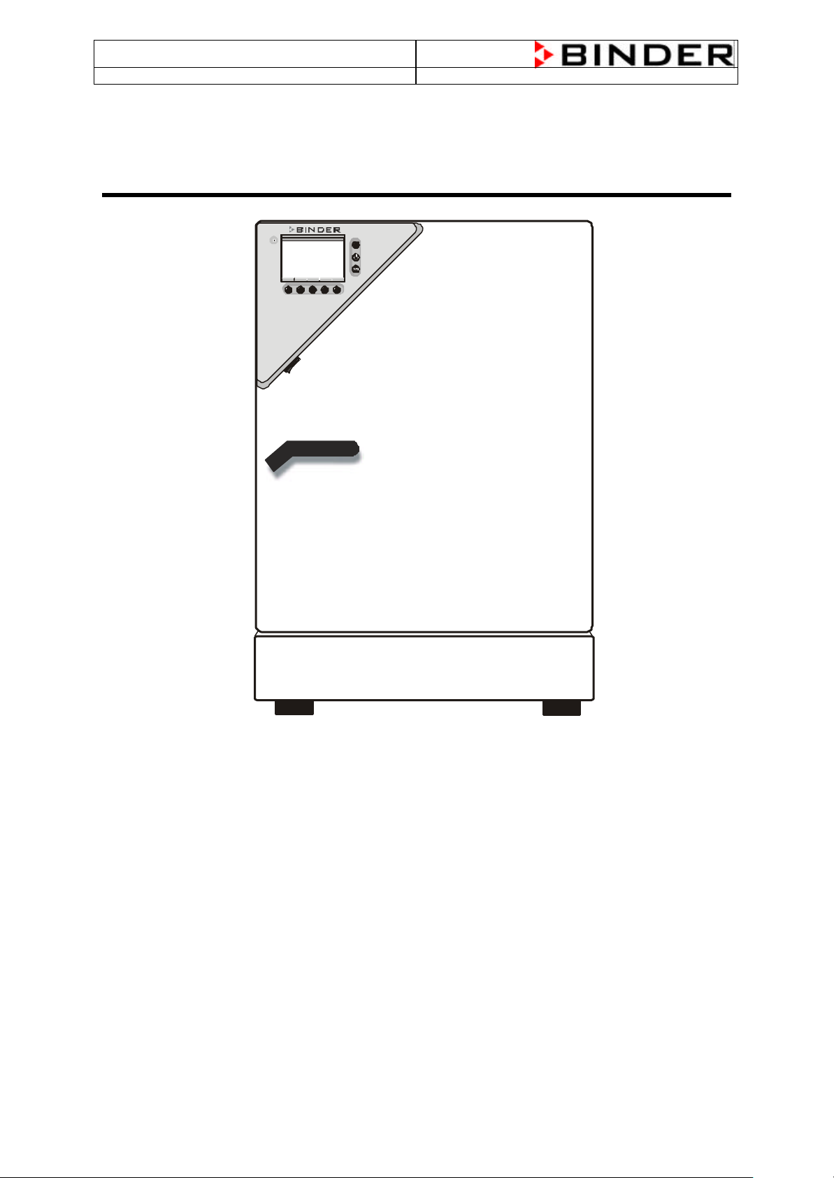
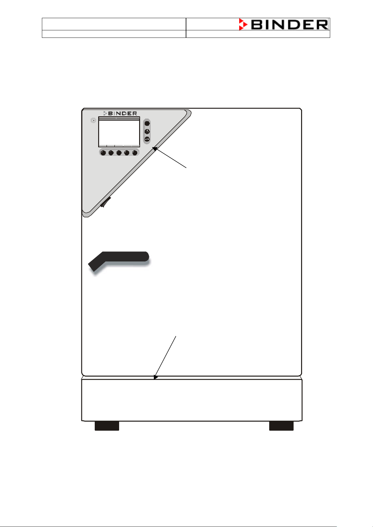
The CB CO2 Incubator E2 is a further development of CB CO2 Incubator E1. Especially the Display
controller MB1 inside the red triangle is conspicuous.
The whole electronic is placed inside the lower part of the CB CO2 Incubator (Front Access
Maintenance). Theres no I-box as at the CB CO2 Incubator E1 at the top of the chamber.
08:43:55 20.11.01
W X
TEMP
TEMP
37.0
5.0
25.0
36.8
4.9
25.2
RESET
C2O
O2
CONFIG W MENUE VIEW->
EXIT
°C
%
%
Display Controller MB1
Display controller MB1
Machine Room with all electronic parts
3
Page 4
CB (E2) Service Manual
Machine room with all
(M)
(F) (K)
state: 01/2002 created: 03/2002/ Jochen Tussinger
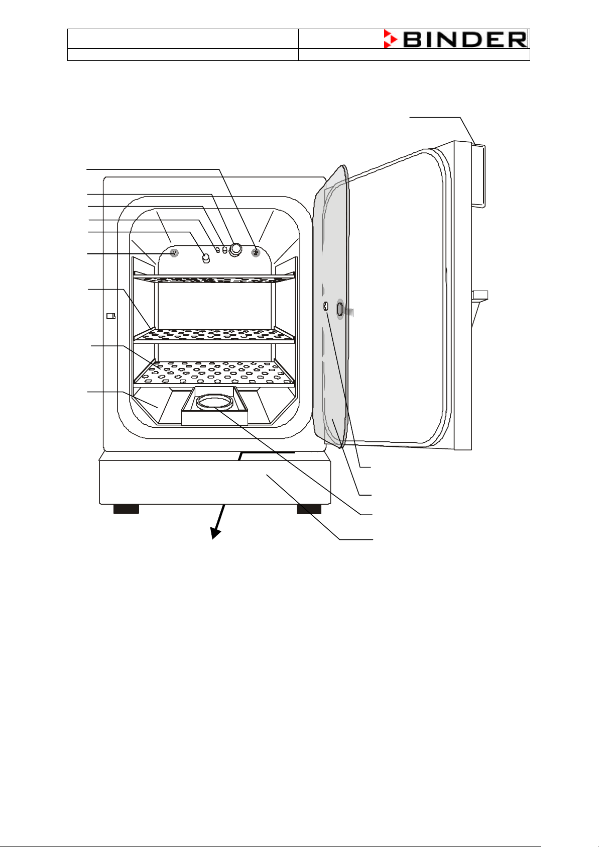
2 Unit overview
(B)
(C)
(D)
(E)
(G)
(H)
(I)
(J)
(A)
FRONT
electronic parts
(N)
(L)
A) Display controller MB1 for temperature and CO2 as well as O2 (option)
B) Connection socket for low tension supply (option)
C) CO2 sensor
D) Gas mixing head
E) PT 100 temperature probe
F) O2 sensor (option)
G) Internal socket 230V (max. 3 A) (option)
H) Shelf holder bar
I) Shelves
J) Shelf holder
K) Lower housing cover
L) Permadry® water basins
M) Inner glass door
N) Measuring access port
4
Page 5
CB (E2) Service Manual
5.0
VIEW->
Display Controller MB1
state: 01/2002 created: 03/2002/ Jochen Tussinger
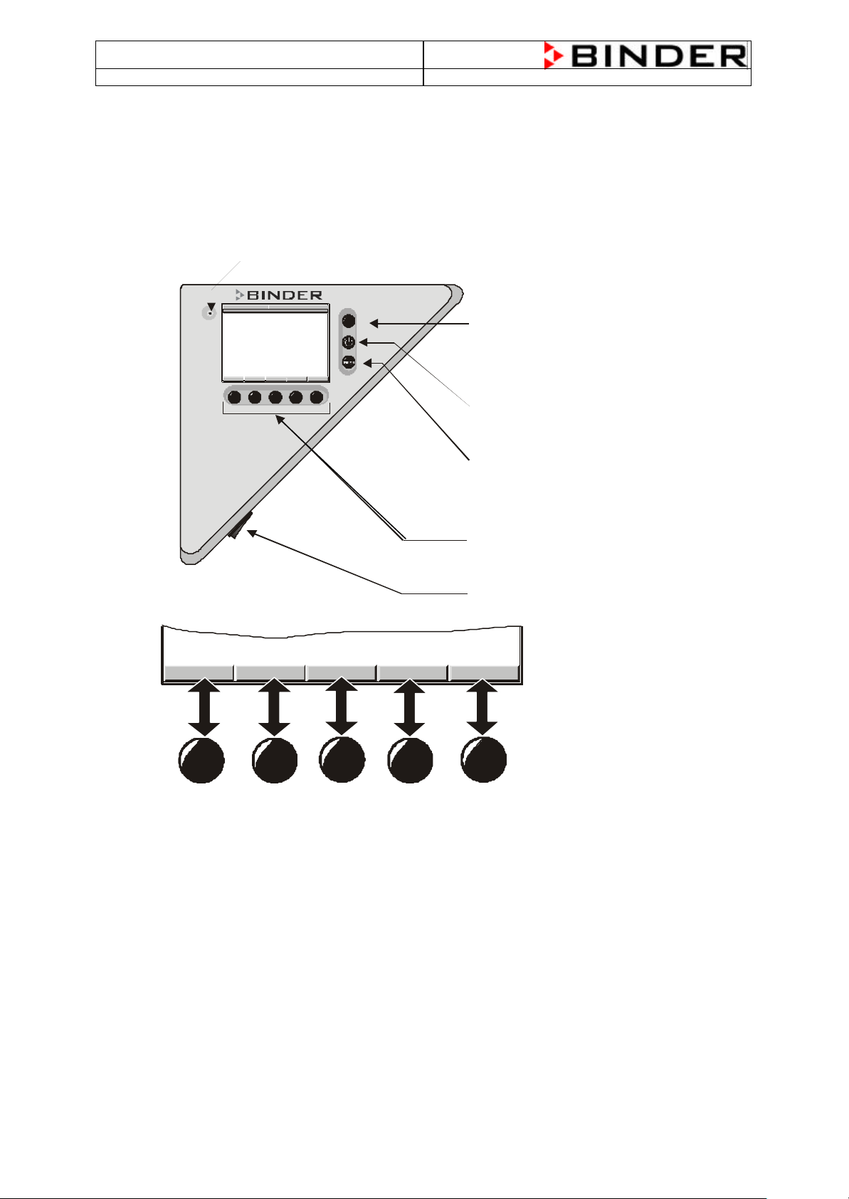
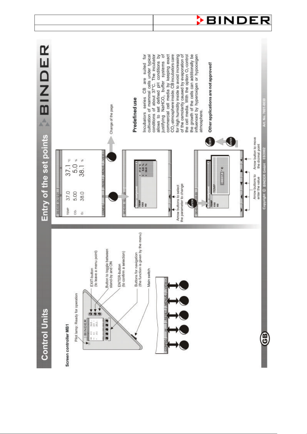
2.1 The Controller MB1
Operating Light
08:43:55 20.11.01
W X
TEMP
37.0
TEMP
C2O
O2
25.0
36.8
4.9
25.2
EXIT
°C
%
%
EXIT-Button
(to leave a
Menue)
CONFIG W MENUE VIEW->
RESET
ON / OFF Button
(Stand-by)
ENTER-Button
((to confirm a
selection)
Navigation buttons
(corresponding function
will be assigned)
Mainswitch
CONFIG
W
RESET
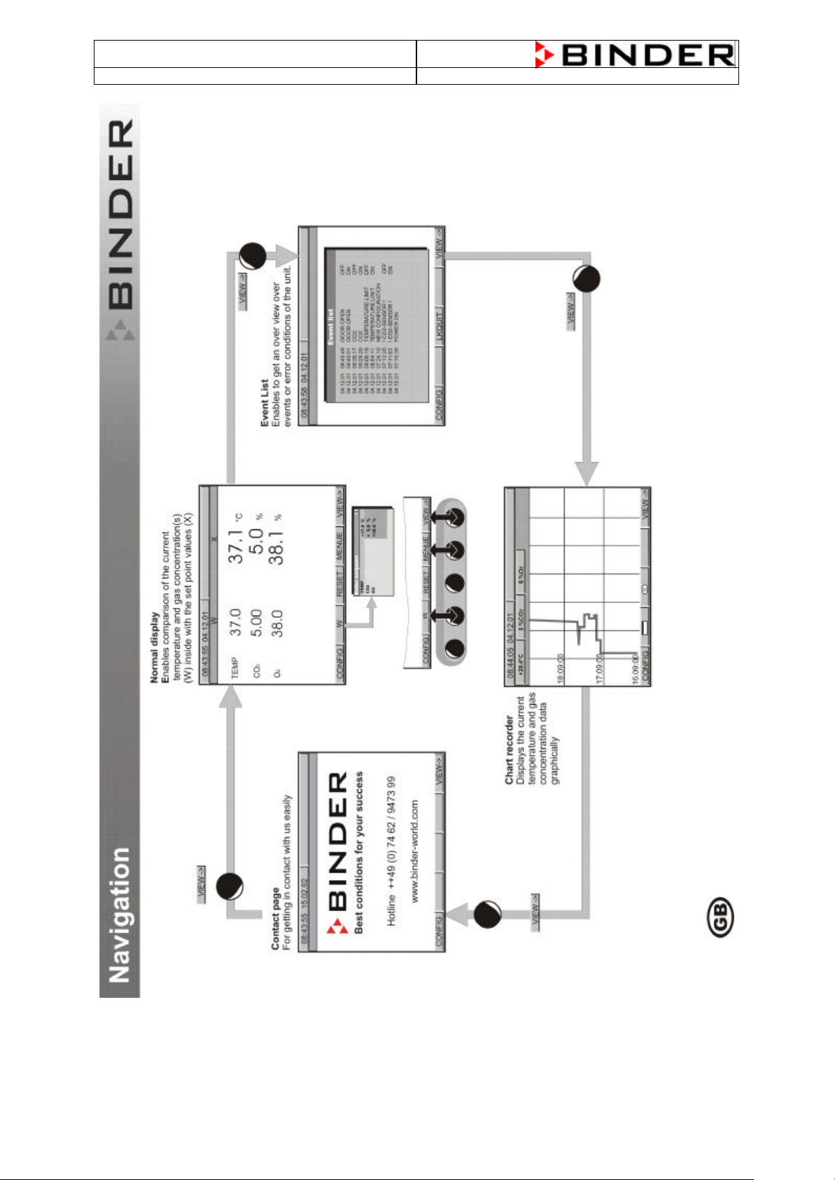
For the controller MB1, it is possible to show all setpoints an d actual values at the same time.
It is also possible to display the actual values portrary.
MENUE
5
Page 6
CB (E2) Service Manual
state: 01/2002 created: 03/2002/ Jochen Tussinger
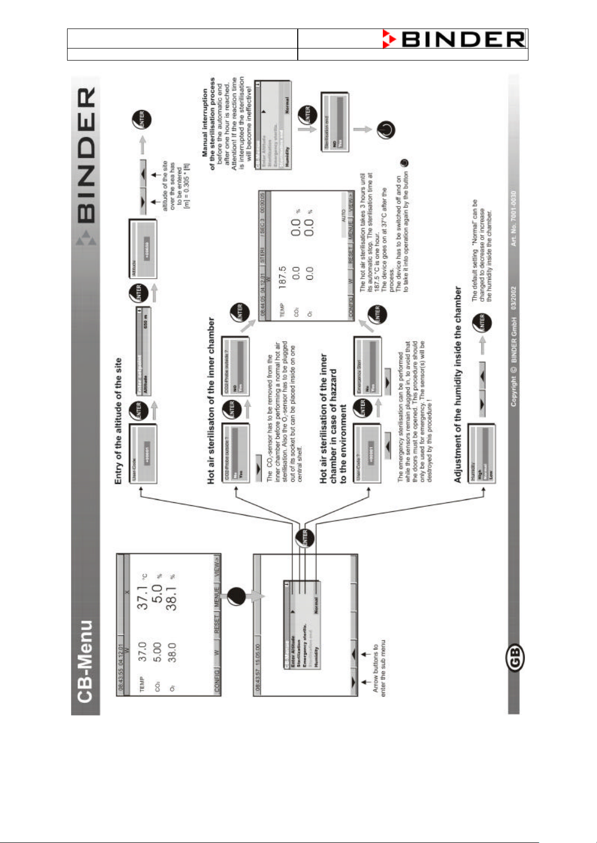
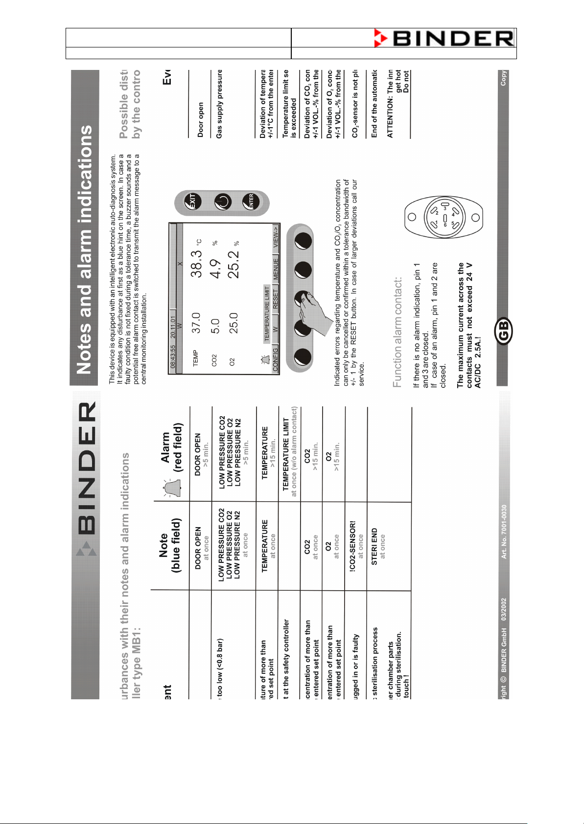
2.2 Short description of the MB1 Controller
6
Page 7
CB (E2) Service Manual
state: 01/2002 created: 03/2002/ Jochen Tussinger
7
Page 8
CB (E2) Service Manual
state: 01/2002 created: 03/2002/ Jochen Tussinger
8
Page 9
CB (E2) Service Manual
state: 01/2002 created: 03/2002/ Jochen Tussinger
9
Page 10
CB (E2) Service Manual
state: 01/2002 created: 03/2002/ Jochen Tussinger
10
Page 11
CB (E2) Service Manual
state: 01/2002 created: 03/2002/ Jochen Tussinger
,,
11
Page 12

CB (E2) Service Manual
state: 01/2002 created: 03/2002/ Jochen Tussinger
3 Function
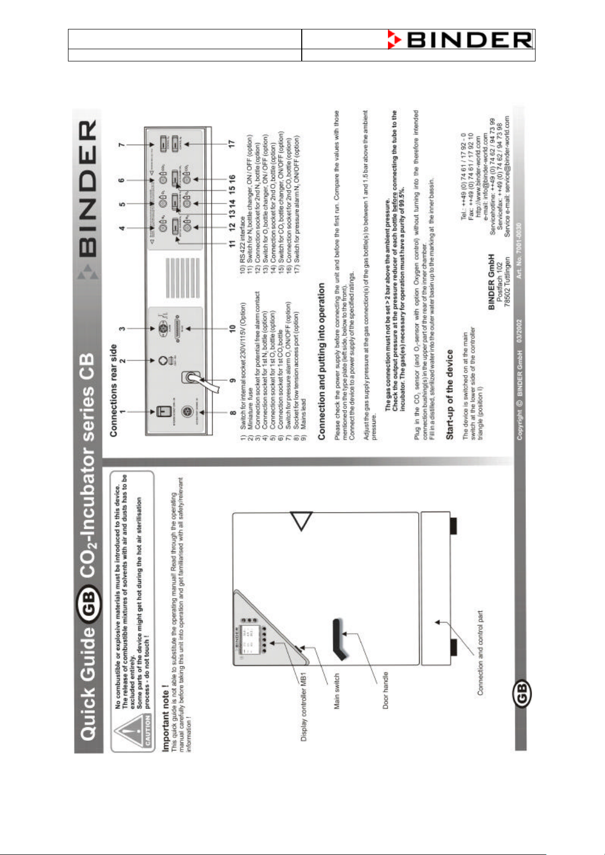
Incubators series CB are suited for cultivation of mammal cells under typical conditions of about 37°C.
The incubator allows the set defined pH conditions by justifying NaHCO3 buffer systems of commercial
cell media by keeping exact CO2-atmosphere inside. CB incubators care for high humidity inside to
avoid increasing of the osmolarity caused by evaporation of the cell media. To reach this, the different
functions heating, sterilization and CO2 injection have to work as a perfect team. This know-how is as
Firmware inside the controller type MB1.
3.1 The CO2-measuring principle
The CO2-measuring procedure of the incubator series CB is characterized by fast reaction times, as
well as the highest accuracy and selectivity. The accuracy of the CO2 measuring system bases on a
single-beam infrared measuring cell, which measures in di fferential mode, with permanently
alternating transmission characteristic of its semi-conductor filter. Due to this highly developed single beam principle with Fabry -Perot interferometer (FPI), disturbance variables and aging phenomena in
the measuring system are almost completely eliminated, so that this measuring system, in contrast to
other measuring procedures, remains practically drift -free between calibrations and is absolutely
selective for CO2.
The CO2–measuring cell contains a measuring section ins ide in which the absorption of infrared light
depends on the number of CO2-molecules in the beam path. This number of CO2 –molecules changes
with the ambient pressure in relation to a constant volume. The distances between the molecules are
consequently pr essure-dependent. The collision frequency of the IR-beam with CO2-molecules
increases therefore by increasing pressure.
For this reason, the ambient pressure must be compensated in order to correct the display reading of
the CO2-concentration in VOL. -%. This is achieved by entering the altitude of the site above the sea
which is described in this manual.
3.2 Function of the Heating System
The temperature measurement is realized by a PT100 temperature probe which changes his resistance
at different temperatures . For example: 37°C = 114,380 Ω (see following chart).
The CB is equipped with a double PT100, one part is for the measurement inside the chamber, the
other part is connected to the safety device class 3.1.
The measured value is evaluated in the controller MB1. The controller MB1 compares the set -value
and the now measured value and decides to give a signal-current to the solid state relay –4K3 to
activate the heating.
12
Page 13
CB (E2) Service Manual
Measuring of the Pt100 resistance between the white
state: 01/2002 created: 03/2002/ Jochen Tussinger
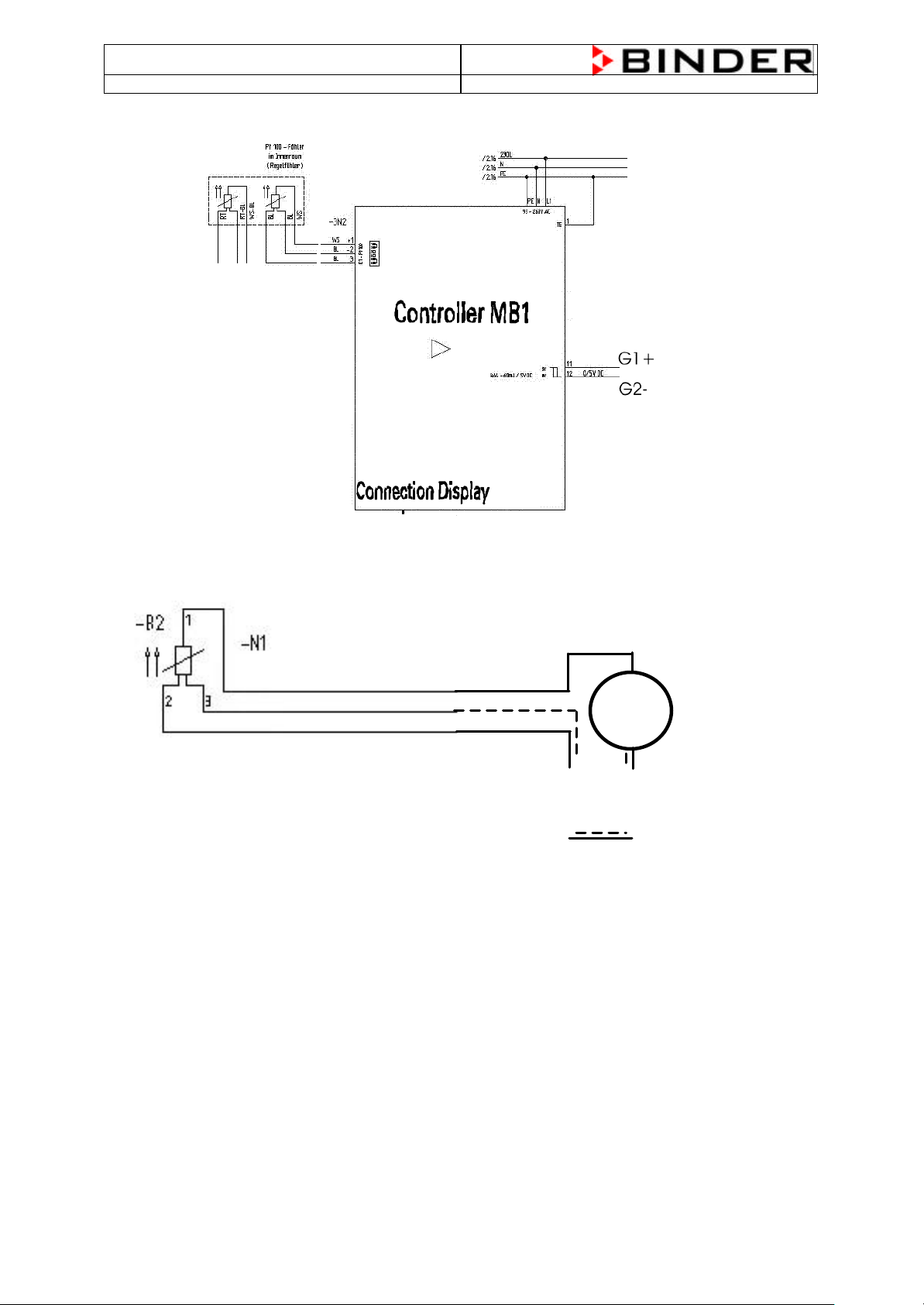
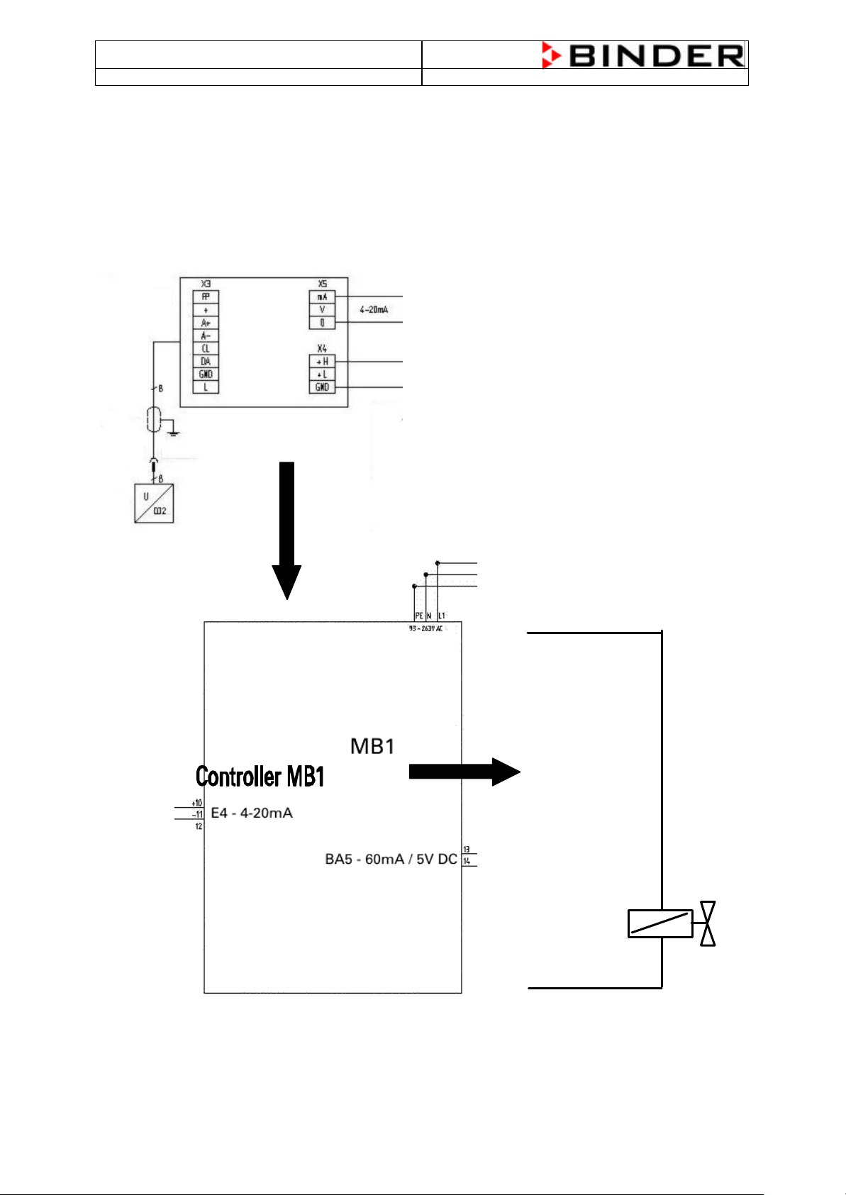
3.3 Flow-Chart of the heating function (basis CB 150 wiring diagram)
The Pt100 temperature probe is equipped with 3 cables, two red and one white cable.
The white cable is connected to pin 1 at E1 – Pt100, the two red cables at pin’s 2 and 3 at E1 – Pt100.
To measure the resistance disconnect all three cables from the controller an measure between the
white cable and one of the red cables, do not measure between both red cables.
Ω
cable PIN 1 and one of the two red cables PIN 2 or 3
13
Page 14
CB (E2) Service Manual
BE1 BE2 BE3 BE4
Output Phase
-
controll
3A / 115
-
230V AC
Heater air
-
duct
BA2 – 1A / 115
-
230V AC
Door Heater
BA3 – 1A / 115
-
230V AC
Collection Alarm
BA1 – 3A / 115
-
230V AC
Ground TE
Heater Kettle
BA4 – 60mA / 5V DC
CO2 Solenoid valve
BA5 – 60mA / 5V DC
Safety device Cl 3.1
BA6 – 60mA / 5V DC
Fan Cold water bassin
0(2)-10V / 0(4)
-
20mA
Volatge output
45mA / 24VDC
state: 01/2002 created: 03/2002/ Jochen Tussinger
Pt100 temperature probe (Temperature in °C / Resistance in Ω)
T (°C) 0 1 2 3 4 5 6 7 8 9 10
-10
0
10
20
30
40
50
60
70
80
90
100
96,086 96,478 96,870 97,262 97,653 98,045 98,436 98,827 99,218 99,609 100,000
100,000 100,391 100,781 101,172 101,562 101,953 102,343 102,733 103,123 103,513 103,902
103,902 104,292 104,681 105,071 105,460 105,849 106,238 106,627 107,016 107,404 107,793
107,793 108,181 108,570 108,958 109,346 109,734 110,122 110,509 110,897 111,284 111,672
111,672 112,059 112,446 112,833 113,220 113,607 113,994 114,380 114,767 115,153 115,539
115,539 115,925 116,311 116,697 117,083 117,469 117,854 118,240 118,625 119,010 119,395
119,395 119,780 120,165 120,550 120,934 121,319 121,703 122,087 122,471 122,855 123,239
123,239 123,623 124,007 124,390 124,774 125,157 125,540 125,923 126,306 126,689 127,072
127,072 127,454 127,837 128,219 128,602 128,984 129,366 129,748 130,130 130,511 130,893
130,893 131,274 131,656 132,037 132,418 132,799 133,180 133,561 133,941 134,322 134,702
134,702 135,083 135,463 135,843 136,223 136,603 136,982 137,362 137,741 138,121 138,500
138,500 138,879 139,258 139,637 140,016 140,395 140,773 141,152 141,530 141,908 142,286
For Example: Your resistance measurement system shows you 114,380 Ω this corresponds to 37°C.
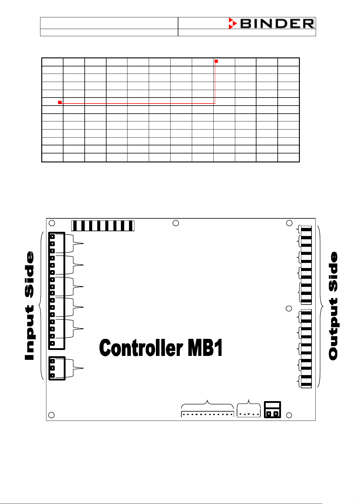
3.4 Controller MB1 PIN description (Input / Output)
E1 – Pt100
E2 – Pt100
E3 – Pt100
E4 – 4 - 20mA
E2 – Pt100
E – Safety device class 3.1
Display connection
RS422
14
Page 15
CB (E2) Service Manual
To A1+ / A2
-
1 – white
state: 01/2002 created: 03/2002/ Jochen Tussinger
3.5 Function of the CO2 System
The CO2 System measures the CO2 concentration inside the chamber. This information is supplied by
the FPI Sensor Head. The Controller MB1 compares the engaged value with the now measured value
and decides to open the solenoid valve of the CO2 gas inlet.
3.6 Flow Chart of the CO2 System (basis CB wiring diagram)
FPI-Sensor à FPI Sensor Board à Controller MB1 à Solenoid Valve à Gas Injection Nozzle
2 – grey
3 – green
4 – yellow
5 – blue
6 – red
7 – brown
8 - pink
To Power supply at the Transformer
H1+
Solenoid Valve CO
2
1
-5Y1
2
H2-
15
Page 16
CB (E2) Service Manual
Lettering
state: 01/2002 created: 03/2002/ Jochen Tussinger
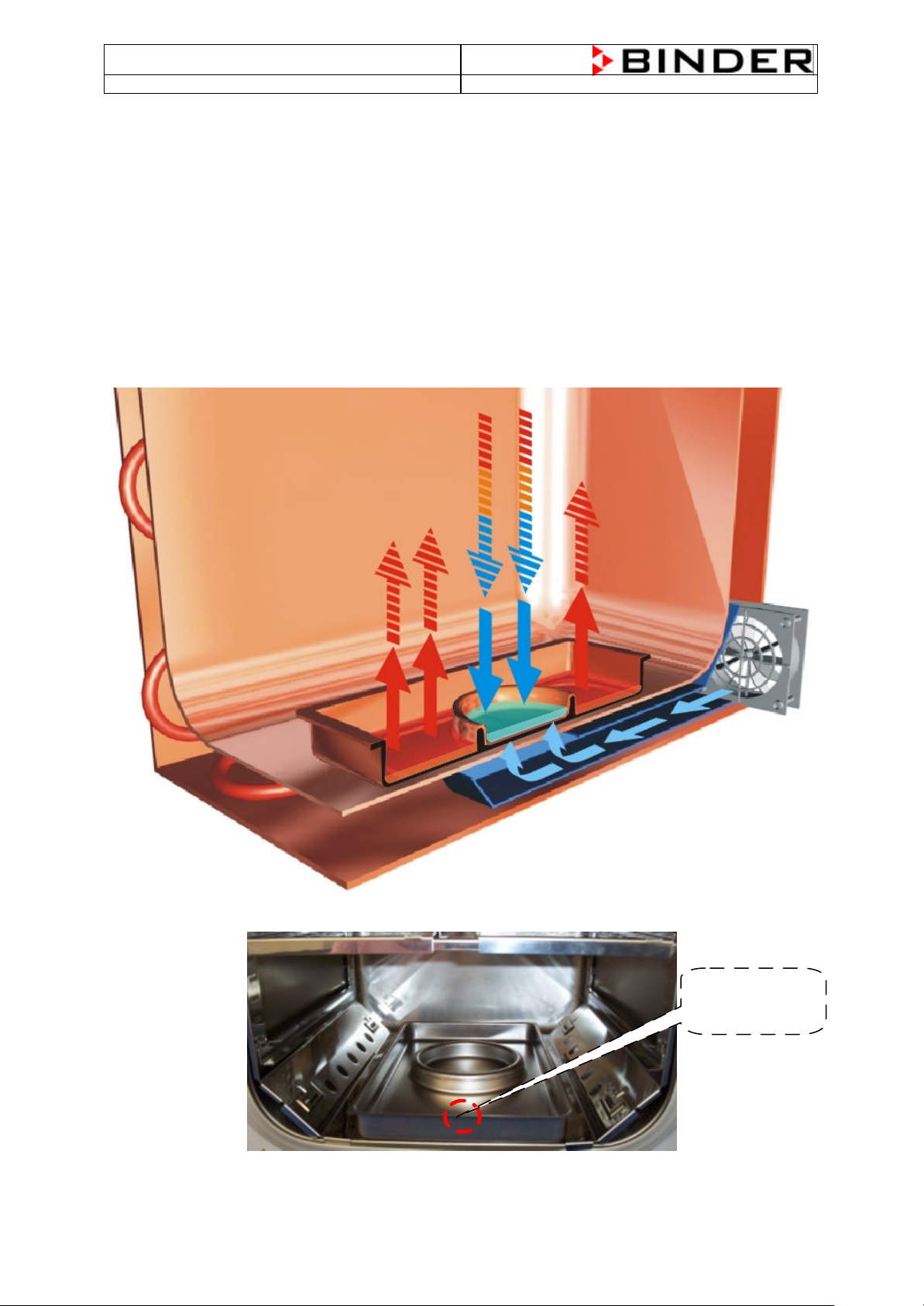
3.7 Function of the Permadry® system
Isotonic osmotic pressure ratios, essential for the growth of cells, are basically maintained in CO2
incubators by a maximum humidity content in the inner chamber. During this process care must be
taken to ensure the best possible protection against contamination.
The patented Permadry® system guarantees a humidity performance of up to 98% relative humidity
with completely dry inner walls. The principle hereof is totally easy. The double basin system consists
of a large-surface warm water basin an a cold water basin as defined condensation point. The
temperatures of both basins are in that way controlled that the humidification and the dehumidification
are permanently balanced. The Permadry® system works completely free of disturbances or
maintenance. The handling of the Permadry® system is the easiest thing and as safe as a coffee cup.
The basin is easily removable and can be refilled in or at the unit at any time.
Cold air, produced by the Permadry® -fan, streams through the air -channel and cools the round cold
water basin. The condensation point is fixed by this.
The Permadry® water basin must be placed correctly. There is a description „FRONT“ impressed.
„FRONT“
16
Page 17

CB (E2) Service Manual
state: 01/2002 created: 03/2002/ Jochen Tussinger
3.8 Flow Chart of the Permadry® system (basis CB wiring diagram)
Controller MB1 à Permadry® fan
3.9 Description of the Function of the Fan Control
The CB heats up to the engaged set -value (°C), just before the chamber reaches the set -value the
controller MB1 starts to pulse the heating signal. The ON/OFF rate is assigned by the regulation ration
of the controller MB1.
The higher the regulation ratio, the higher is the fan speed. If the chamber doesn’t heat (regulation
ratio = 0) the fan is working with his minimal speed. If the chamber heats continuing (regulation ratio =
100%) the fan is working with his maximum speed. The speed of the fan is reduced to avoid kinetic
influence of heating
The rotation of the Permadry®-Fan is reverse proportional to the rotation of the Mainfan.
The only difference is: The Mainfan is controlled constant with the help of a phase control level, the
Permadry®-Fan is in interval mode which is given by a solid state relay.
17
Page 18

CB (E2) Service Manual
state: 01/2002 created: 03/2002/ Jochen Tussinger
3.10 Sterilization Mode
Depending on the resistance level of the germs, attention must be paid to the quality of the sterilizat ion
procedure. The lower the sterilization temperature the higher the risk of remaining germs and the
longer the sterilization time is. With the standard hot air sterilization at 187,5°C it is absolutely
guaranteed that all germs are reliably eliminated an d, furthermore also time is saved.
All unit parts in the inner chamber are auto sterilized at a temperature of 187,5°C. The precision IR
sensor is separately treated in a desinfectant bath. This ensures that the measuring quality does not
suffer from the high temperature, as it may happen with other systems.
3.11 Hot-air sterilization
The hot -air sterilization gets activated in the CB Menu. The sterilization temperature of
187,5° C is adjusted by the manufacturer. It may not be changed.
The CO2 sensor is temperature resistant up to a maximum temperature of 60° C.
By no means it can be sterilized or autoclaved.
The CO2-sensor head is especially adjusted for a specific chamber that it belongs to. It cannot
be operated in another chamber. There is an adhesive label with a number on the sensor head
to avoid any mixing up.
Effect the hot -air sterilization as following:
1. Switch off the unit.
2. Pull out the CO2 sensor (without rotating) from the connection bushing in the upper part of the rear
and remove it from the inner chamber.
3. Only with option Oxygen control: Remove the oxygen sensor from the connection bushing without
rotating and put it on the middle shelf.
4. Before starting the sterilization, please remove the water from the basin.
5. Shut the outer and the inner door of the unit.
6. Ensure that the water basins, the shelf holder and the shelves are in the inner chamber.
7. Switch on the unit.
8. Unlock the keypad of the controller MB1 with the key switch (option)
(unlocked = horizontal position, key is removable).
9. Activate the sterilization procedure in the CB Menu as following:
18
Page 19

CB (E2) Service Manual
TEMP
187.5
HANDHANDHANDAUTO
Sollwert Art
Offset
CO2-Probe outside ?
No
Yes
Sollwert Art
NO
Yes
CB-Menue
Enforced steriliz.
Normal
CB-Menue
Emergency steriliz.
Normal
Display during the
state: 01/2002 created: 03/2002/ Jochen Tussinger
Enter Altitude
Enter Altitude
Sterilization
Sterilization
Sterilization end
Sterilization end
Humidity
Humidity
08:44:05 04.12.01
CO
2
O
2
CONFIG
W
0.0
0.0
W RESET
STERI / SEC 3 00:00:05
0.0
0.0
%
%
MENUE VIEW->
sterilization process
Caution: Never open the two unit doors during the sterilization process, as the temperature
reaction time will be interrupted and the sterilization will become ineffective.
10. The hot-air sterilization is automatically finished after 3 hours.
11. Switch off the unit and open the outer door.
The temperature of the glass door handle is about 150°C. Use gloves or a tool (e. g. pincers)
for opening the glass door, or let the unit cool down as follows: with opened front door for at least
1 hour, with closed front door at least 4 hours. Please make sure that the unit has cooled down
to ambient temperature, but down to at least 60° C before plugging in the CO2 sensor. In case of
doubt, please wait at least 2 hours.
12. Befor putting into operation, please plug in the CO2 sensor. Optional also the O2 Sensor.
Due to the sterilization, units in copper version change their colour. This does not have any negative
effect on the function and quality of the unit.
Caution danger of burning !
Due to the increased temperature performances there is the risk of burnings at the marked unit
parts and especially at the inner glass door.
Do not touch !
19
Page 20

CB (E2) Service Manual
TEMP
187.5
08:44:05 04.12.01
HANDHANDHANDAUTO
STERI / SEC 3 00:00:05
Sollwert Art
User-Code ?
+00001
Sollwert Art
Offset
Emergency Steri
No
Yes
Enforced steriliz.
Normal
Emergency steriliz.
Normal
Sollwert Art
User-Code ?
+00000
Display during the
emergency sterilization
state: 01/2002 created: 03/2002/ Jochen Tussinger
3.12 Hot-air sterilization with inner chamber
contaminated with highly infective material
If it is not possible to discharge the unit and to remove all necessary parts for safety reason, the hot -air
sterilization can exceptionally be done nonetheless.
Attention! Note that this procedure destroys the CO2 and the O2 sensor (option)!
1. Shut the outer and the inner door of the unit.
2. Switch on the unit.
3. Unlock the keypad of the controller MB1 with the key switch (option)
(unlocked = horizontal position, key is removable).
4. Activate the emergency sterilization procedure in the CB Menu as following:
CB-Menue
CB-Menue
Enter Altitude
Enter Altitude
Sterilization
Sterilization
Sterilization end
Sterilization end
Humidity
Humidity
Grenzwert
Offset
Grenzwert
Offset
W
CO
2
0.0
O
2
0.0
CONFIG MENUE VIEW->
W RESET
0.0
0.0
%
%
process
20
Page 21

CB (E2) Service Manual
state: 01/2002 created: 03/2002/ Jochen Tussinger
Caution: Never open the two unit doors during the emergency sterilization process, as the
temperature reaction time will be interrupted and the sterilization will become ineffective.
5. The emergency hot-air sterilization is automatically finished after 3 hours.
6. The incubator is no longer ready for operation. Contact the BINDER service for repair.
(As CO2 Sensor and/or O2 Sensordestroyed)
Due to the sterilization, units in copper version change their colour. This does not have any negative
effect on the function and quality of the unit.
Caution danger of burning !
Due to the increased temperature performances there is the risk of burnings at the marked unit
parts and especially at the inner glass door.
Do not touch !
21
Page 22

CB (E2) Service Manual
too high inside the
Sensor System is defect. The Sensor outputsignal of the
0,24mA you can
roller as described in chap.
state: 01/2002 created: 03/2002/ Jochen Tussinger
4 Trouble Shooting
Safety hints: Do never unplug the CO2 sensor head while the chamber is switched on.
This could result in sensor destruction or initiation problems.
Hint: The tradename of the controller is MB1
Fault description Fault cause
High CO2 consumpt ion
CO
2
chamber
par example cell-medium is
colored yellow = CO2 too high
• If when the CO2 is connected the max. pressure of 1,5 bar is
exceeded, this can lead to a defect in the pressure switch.
The pressure switch becomes leaky as a result and loses gas.
The controller MB1 shows also a too high concentration of CO2:
• MB1 controller output which controlls the gas inlet valve is defect.
There are continually 5V DC at controller output BA5.
• The solenoid valvet is mechanically defect, it doesn’t close.
• The controller MB1 doesn’t show a too high concentration of
CO2:
The FPIFPI-Sensor board could be checked according the following chart.
Binder offers a calibration kit for this purpose with analyzed test gas
with a CO2-concentration of 5 Vol.-%. Because the atmospheric
pressure influences the measurement result of the CO2 sensor system,
the altitude of the site has to be taken into consideration.
Expected results during exposing the sensor head to 5% test gas:
Sea Level Sensor Current
0 m 8,00 mA
100 m 7,93 mA
200 m 7,86 mA
300 m 7,79 mA
400 m 7,72 mA
500 m 7,66 mA
600 m 7,60 mA
700 m 7,55 mA
800 m 7,49 mA
900 m 7,44 mA
1000m 7,39 mA
If this values are not reached with a tolerance of +/- 0,24mA
(corresponds to 0,3 Vol % CO2) between the signal output of the FPI
sensor board and the MB1 controller input from the sensor system is
faulty.
• Replace the FPI sensor head and check the sensor current against
the expected value again during exposing the sensor head to test
gas.
If the deviation is now within the tolerance of +/proceed a re-calibration at the MB1 cont
re-calibration to achieve maximum accuracy.
• If this values are reached with a tolerance of +/- 0,24mA at the
signal output of the FPI sensor board and yet the MB1 controller
shows not a reading between 4,8 or 5,2 Vol.-% the MB1 is not
calibrated correctly or it is faulty. Check the correct setting of the
altitude above see level which is essentially for correct CO2 values
displayed on MB1-controller display (see CB operating manual). Try
a re -calibration (see chapter re-calibration) with the correct altitude
setting set before.
22
Page 23

CB (E2) Service Manual
also when there is no
state: 01/2002 created: 03/2002/ Jochen Tussinger
MB1 controller display shows
CO2 readings of 19 to 20 Vol.% CO
2
CO2 inside the chamber e.g.
with open door.
FPI sensor board:
Red and green error LED flash
alternately
FPI sensor board:
Green LED flashes and lights
alternately.
FPI sensor board:
Red LED is continuously on or
flashes (green remains off)
during normal operation
CO2 too low inside the
chamber
par example cell -medium is
colored violet = CO2 too low
• This means the new plugged CO2 sensor head is not initialized
successfully.
• Try a restart of the chamber by switching OFF and after 10 s ON an
the main switch.
• If this worse reading still remains the sensor board has to be
replaced and a re-calibration must be carried out.
• This means no connection between sensor head and the FPI
sensor board.
• The sensor head is not plugged correctly – try to plug it again.
• The red silicone wire between the Lemo socket for the sensor head
and the FPI sensor board is faulty.
• The soldered contacts of the Lemo socket might be unfixed.
• Normal function, no defect.
• Sensor system is faulty. The sensor head and may be the sensor
board must be replaced. The system must be re-calibrated (see
chap. re -calibration)
The controller MB1 shows also a to low CO2 concentration:
• Check the pressure of the CO2 bottle (max.1.5 bar, min. 1.0 bar)
• Sterilization process has to be off
• Check gas inlet valve. When the door is closed the valve has to
open with a clicking noise.
• The door switch has to be in closed position when the door is
closed. If it is not closed no CO2 can flow inside the chamber. Press
the door switch by hand and check on the inlet tube whether CO2 is
flowing in
• Check CO2 connection (rear), and the 1mm drill hole of the gas
mixing head. May be there is something jammed.
The controller MB1 doesn’t show a to low CO2 concentration:
The CO2 Sensor System is defect. The Sensor Outputsignal of the
FPI-Sensor board to the controller MB1 could be checked according
the following chart.
Binder offers a calibration kit for this purpose with analyzed test gas
with a CO2-concentration of 5 Vol.-%. Because the atmospheric
pressure influences the measurement result of the CO2 sensor system,
the altitude of the site has to be taken into consideration.
Expected results during exposing the sensor head to 5% test gas:
Sea Level Sensor current
0 m 8,00 mA
100 m 7,93 mA
200 m 7,86 mA
300 m 7,79 mA
400 m 7,72 mA
500 m 7,66 mA
600 m 7,60 mA
700 m 7,55 mA
800 m 7,49 mA
900 m 7,44 mA
1000m 7,39 mA
If this values are not reached with a tolerance of +/- 0,24mA
(corresponds to 0,3 Vol % CO2) between the signal output of the FPI
sensor board and the MB1 controller input from the sensor system is
faulty.
23
Page 24

CB (E2) Service Manual
state: 01/2002 created: 03/2002/ Jochen Tussinger
• Change the FPI Sensor Head and check the Sensorcurrent against
the table above during exposing with 5% CO2 Testgas
• If the deviation is within the tolerance of +/- 0,24mA, please make a
re-calibration.
• If the value with the tolerance of +/- 0,24mA at the signal output of
the FPI Sensor board is reached but the controller doesn’t show a
value between 4,8 and 5,2 Vol.-% CO2, there was a wrong
calibration done. Check the correct setting of the altitude and make
a re-calibration.
• Make sure, that you have reset the old calibration.
The CO2 concentration doesn’t
go down after a door opening
of approx. 20s to 0 Vol.-% CO
• Check the altitude setting at the MB1 controller
• The Sensor system is defective or wrongley calibrated
2
• Make a re -calibration and check if the value is now ok.
• If not, you have to change the sensor system. Change first only the
FPI sensor head and make a re-calibration.
The CO2 concentration drifts
during exposing with 5% Testgas
CO2 Controller shows „-1999“.
There’s also a red alarm-bell
blinking
• If the signal doesn’t reach a stable value, you have to change the
sensor system, first only the FPI sensor head, after that you have to
make a re -calibration
Means measurement value underrange:
• The Sensor signal between the Sensor Board and the Sensorinput
E4 at the controller MB1 is low. (under 4mA)
• Check if the sensor head puts correctly
• Check the cable between the Sensor Board and the controller MB1
looking for a break or a faulty contact.
• Check the cable between the Sensor Board and the sensor
• If the controller gets the correct signal, but shows still –1999, the
input at the controller is defect. The controller must be changed.
• There’s no current from the transformer (24VDC). Check the power
supply for the FPI sensor. Possibly, the fuse is blown (T500mA).
CO2 controller shows ”9999” Means measurement value exceeding
• The sensor signal between the FPI sensor board and the sensor
input at the controller MB1 at Pin E4 is to high (over 20mA) or
there’s a initialization error – try a restart.
• If the red LED of the sensor board is lit permanent, you have to
change the sensor board.
• If not, check the sensor current and the sensor output of the sensor
board.
• Try a re-calibration with analyzed testgas
• If the error reshows, you have to change the controller
To low humidity inside the
chamber
Humidity to high inside the
chamber
• The stpoint of the door heating is to high. (This is a internal setting
of the controller. Please see description in chapter 4.4)
• The Permadry® fan doesn’t run. This fan is for blowing cold air
throgh the air chanel to the cold water basin
Condensation inside
Condensation at the glass
door
• Check the outer door and the inner door fits not tightly
• Check the two door sealing.
• Adjust the door keepi ng
• The door heating element is faulty – Check the resistance (normally
278 Ω).
24
Page 25

CB (E2) Service Manual
state: 01/2002 created: 03/2002/ Jochen Tussinger
5 Most common service work
Please note:
Please unplug when servicing or working on electronic part
It’s for your own protection
25
Page 26

CB (E2) Service Manual
state: 01/2002 created: 03/2002/ Jochen Tussinger
5.1 Changeing of the fan
If it is possible for the intended service work the
mains plug should be pulled.
Note:
The fan motor turns when the chamber is
switched on.
Remove the rear wall of the chamber by use of a
plus driver.
You have to cut the aluminium tape around the
fan mounting plate.
Remove the two connectors to the fan motor.
Removed the 4 screws of the plate of the fan
motor (sheet metal frame).
26
Page 27

CB (E2) Service Manual
state: 01/2002 created: 03/2002/ Jochen Tussinger
Unscrew the axis nut of the fan wheel (left turning
thread !) with a spanner size 13. Remove fan
Assemble the ne w fan motor in reversed order.
Replace Aluminium Tape.
27
Page 28

CB (E2) Service Manual
state: 01/2002 created: 03/2002/ Jochen Tussinger
5.2 Take out of the electronic component board
Open the glass door and then the two screws at
the cover.
After unscrew you have to press down the cover
to take it off.
Now you can change the steri filter.
The cover plate is fixed by 4 screws.
Before you can take out the complete component
board, please check that the power supply is
disconnect.
Please remove the drawn part of the air chanel of
the Permadry® system before you take out the
component board.
Now lift the component board and take them out
forwards.
Now it is possible to change all electronic parts.
If you plug in the power supply to measure some
parts, be carefull, there could be 230V AC.
28
Page 29

CB (E2) Service Manual
1
state: 01/2002 created: 03/2002/ Jochen Tussinger
5.3 Opening of the rear service lid to achieve the area of the air jacket
This is necessary for following service works.
♦ To replace the temperature probe of the air jacket
♦ To replace the socket of the FPI-sensor head
♦ To replace the gas mixing head
♦ To replace the double temperature probe for inn er temperature and safety device
If it is possible for the intended service work the
mains plug should be pulled out.
Note:
The fan motor turns when the chamber is
switched on.
Remove the rear wall of the chamber by use of a
plus driver.
Cut the aluminum foil with a sharp knife at the
upper area as shown.
Note that it should not be cut up all around. Cut
only the top line and the two sides
29
Page 30

CB (E2) Service Manual
3
4
state: 01/2002 created: 03/2002/ Jochen Tussinger
Fold up the insulation as shown beside.
Remove the parker screws which fix the metal
cover.
Remove the metal cover sheet.
Now you have access to following parts:
♦ socket of the FPI-sensor head gas mixing
head double temperature probe for inner
temperature and safety device
Inner view:
♦ left: double temperature probe for inner
temperature and safety de vice
♦ middle: gas mixing head
♦ socket of the FPI-sensor head
30
Page 31

CB (E2) Service Manual
°C % W X CO
08:43:55 04.12.01
.00
Feuchte
Feuchte
08:43:57 15.05.00
08:43:57 15.05.00
System
-
Code ?
08:43:57 15.05.00
System
-
Code ?
08:43:57 15.05.00
SW-Offset Tür
+ 4.0°C
Press the Button up to SW
-
Offset door press
CAUTION:
state: 01/2002 created: 03/2002/ Jochen Tussinger
5.4 Setting of the door heating
This function is needed, to stop condensation at the glass door.
Make sure that the outer and inner door seal tightly
Parametrierung ∇
TEMP
37.0
2
5.00
37.1
5.0
1. 5.
CONFIG
W RESET
MENUE VIEW->
08:43:57 15.05
2. 6.
Benutzer-Daten
Konfiguration 2
Not-Sterilisation
Konfiguration 1
Steri Abbruch
Not-Sterilisation
Parametrierung
Feuchte
Steri Abbruch
Not-Sterilisation
Wahl der Variante
Feuchte
Steri Abbruch
Not-Sterilisation
Steri Abbruch
3.
Benutzer-Daten
Konfiguration 2
Not-Sterilisation
Konfiguration 1
Steri Abbruch
Not-Sterilisation
Parametrierung
Feuchte
Steri Abbruch
Not-Sterilisation
Feuchte
Steri Abbruch
Feuchte
Wahl der Variante
EXIT
ENTER
Now you are at the System-Code input field
4.
+00000
just type 2802 and confrim with ENTER
5.
+02802
ENTER to confirm. Now you can set the desired
value.
Then press EXIT to come back to standard display
The System-Code is only for Service Engineers. Don’t give the System-Code
to the customer, it is possibl eto
change also the parameters, so that the
chamber couldn’t work
31
Page 32

CB (E2) Service Manual
state: 01/2002 created: 03/2002/ Jochen Tussinger
5.5 CO2-Reference Measurement
The CO2-measuring procedure of the incubator series CB is characterised by fast reaction times, as
well as the highest accuracy and selectivity. The accuracy of the CO2 measuring system bases on a
single-beam infrared measuring cell, which measures in differential mode, with permanently
alternating transmission characteristic of its semi-conductor filter. Due to this highly developed single beam principle with Fabry -Perot interferometer (FPI), disturbance variables and aging phenomena in
the measuring system are almost completely eliminated, so that this measuring system, in contrast to
other measuring procedures, remains practically drift -free between calibrations and is absolutely
selective for CO2.
The CO2–measuring cell contains a measuring section inside in which the absorption of infrared light
depends on the number of CO2-molecules in the beam path. This number of CO2 –molecules changes
with the ambient pressure in relation to a constant volume. The distances between the molecules are
consequently pressure -dependent. The collision frequency of the IR-beam with CO2-molecules
increases therefore by increasing pressure.
For this reason, the ambient pressure must be compensated in order to correct the display reading of
the CO2-concentration in VOL. -%. This is achieved by entering the altitude of the site above the sea
which is described in the CB operating manual.
It is a common desire of customers to make test-measurements between the re-calibrations
implemented as a part of the recommended annual maintenance work.
In principal there are 3 possibilities to test CO2-concentration inside a incubator which are described
later on.
32
Page 33

CB (E2) Service Manual
7.4
7.6
pH-value
Trade names of common
state: 01/2002 created: 03/2002/ Jochen Tussinger
5.5.1 Measuring of CO2 indirectly via the pH of the cell medium
By use of the indirect determination of CO2 concentration via the pH-value of the nutrient it is possible
to check the CO2-concentration inside the chamber. This method can not be used for re -calibration of
the sensor system but it is a simple method to test for the correct CO2 concentration without any
special CO2-measuring equipment. Only a accurate pH indicator or a pH measuring electrode is
necessary, but this is standard equipment in cell culture laboratories.
This method bases on the acid base equilibrium of the buffer system in the nutrient.
The most common media are buffered by NaHCO3. With the help of the pH-value in the medium, a
conclusion can thus be drawn about the concentration of CO2.
This conclusion is directly possible using the diagram below, which expresses the interrelationship
between CO2 concentration in vol. % and the pH of different NaHCO3 buffered media.
We recommend the incubation of an empty sample with medium for 1/2 day under the same
conditions as the cells. The incubation can be performed in a cell culture bottle or in a 50 ml Falcon
tube with open lid.
After gassing, remove the empty sample from the incubator and within 5 minutes measure the pH1value with a glass electrode. During the measurement the medium should have the least possible
surface contact with the ambient air, so that the CO2 can only diffuse out slightly. Therefore,
transfusing should be avoided. A significant downward movement will only be observed after 5
minutes, allowing sufficient time for measurement. Naturally, pH -test strips can also be used (pH6-8
range not bleeding).
Following graph shows the pH-value of NaHCO3 buffered media as function of the CO2-concentration:
Vol.% CO2
18
3,70
16
media:
NaHCO3
14
12
10
8
6
4
2
6.8 7.0
2,20
1,20
0,85
0,35
7.2
[g/l]
DMEM 3,70
BME 2,20
MEM 2,20
Medium 199 2,20
Mc Coy 2,20
F10 1,20
F12 1,20
Example:
If a pH of 7,2 is measured in a medium which is buffered with 2,20 g NaHC03 per liter there must be 8
Vol.-% CO2 in the surrounding of this medium.
33
Page 34

CB (E2) Service Manual
state: 01/2002 created: 03/2002/ Jochen Tussinger
5.5.2 Measuring of CO2 directly via chemical indicator tubes
This is a common do it yourself test of the users. A chemical color reaction in a glass tube shows the
CO2-concentration. A standardized volume of air from the inside of the incubator has to be sucked
through this glass tube to get a quantitative test result. Therefor a special hand pump must be used
with a standardized suction volume.
Example for such a procedure:
1) Break off both ends of such a glass tube or
remove the plugs.
2) Pin that end with the higher end of the scale
on the adapter of the hand pump which
belongs to that test system.
3) Pin the other end trough the silicon plugged
access port of the inner chamber door (4) of
the CB incubator.
4) Take one sample volume out of the inner
camber volume by pressing the pump entirely
together and releasing it afterwards.
5) The standardized volume is sucked trough the
glass tube and the chemical indicator changes
its color beginning from the side pinned into
the chamber in direction to the hand pump.
6) The more CO2 is inside the chamber the vast
the chemical reaction will cause a change of
the color of the chemical reactor.
7) The CO2 concentration can be read off by the
scale directly printed on the glass tube or a
delivered reference reading rule.
It is necessary to correct the result with the
current ambient pressure. The necessary
formula is printed on the instruction sheet of
such systems.
Notes:
All the necessary equipment must be delivered by
only one manufacturer and one defined test
system.
This test systems are nor very accurate.
A typical accuracy is around 10% of the full scale
value!
Therefor this system should not be used for re calibrating the BINDER FPI-sensor system.
Example for chemical indicator tubes
Example for hand pump (foreground) or a
electrical pump (background)
34
Page 35
CB (E2) Service Manual
Ž Œ
state: 01/2002 created: 03/2002/ Jochen Tussinger
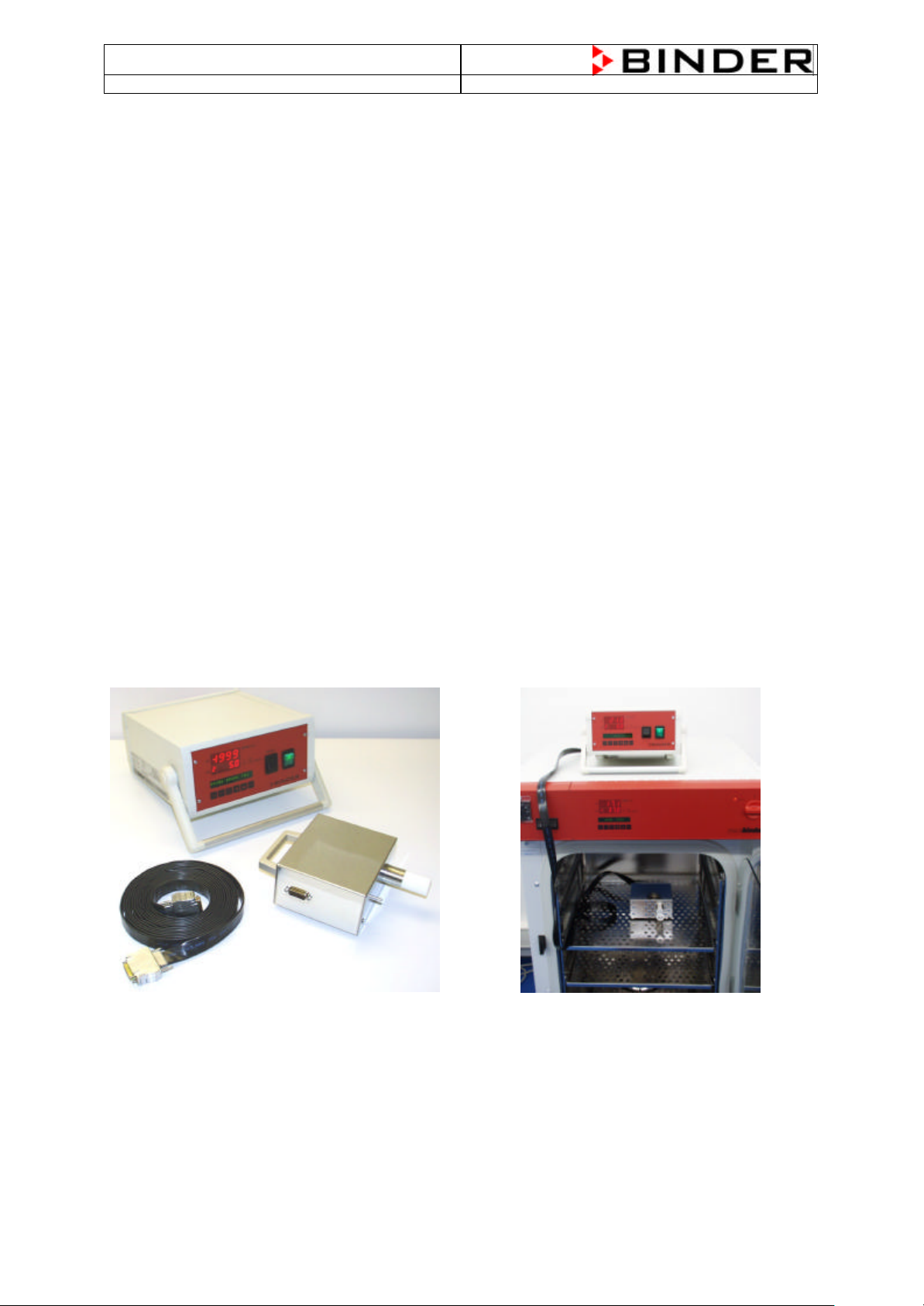
5.5.3 Measuring of CO2 directly via a electronic measuring device
The easiest way to measure CO2 concentration are electronic sensor systems. BINDER offers the
portable measuring device model CTM 01 which were specially designed to measure CO2
concentration and temperature inside of CO2 incubators. The CTM 01 can be used both for reference
measurements in certified laboratories, as well as for service purposes.
Description of CTM01:
• The measuring system consists of 2 parts: The measuring station, which remains outside the CO
incubator, and the sensor housing, which is put in the center of the usable volume of the
incubator. Both parts are connected by a ribbon cable, which can be laid across the door gasket of
the incubator without causing leakage.
• The measuring cell is placed directly in the atmosphere to be measured. This means that there is
no requirement for gas pumps, whose inconstant flow rates can cause inaccuracies. When
converting the measured variable, partial pressure CO2, to the display value, VOL. -% CO2, the
respective altitude above sea level is entered and taken into account, so that the display value
always corresponds immediately to the real concentration in VOL. -% CO2 , irrespective of the
place of use.
• The temperature is determined via a PT100 temperature sensor and is displayed on the large LED
display in 10 seconds alternation with the CO2 - concentration.
• The measured data of temperature and CO2 -concentration are output to an RS 422 interface.
Thus the measured data can be simple recorded, stored and graphically represented via PC using
the APT-COM communication software developed by BINDER.
• For monitoring, the nominal values set in the incubator can be entered into the mobile measuring
system. If these nominal values are exceeded or fallen below by permanent ly set tolerances, this
is reported by the unit optically and acoustically, as well as via a potential-free alarm contact. The
alarm function only becomes active if both measured values were previously within the tolerance
limits.
2
ΠMeasuring station
• Sensor housing
Ž Ribbon cable
•
Measuring in a BINDER incubator type CB
(door is normally closed during measurement)
35
Page 36

CB (E2) Service Manual
state: 01/2002 created: 03/2002/ Jochen Tussinger
6 Calibration
6.1 Definition of calibration
In this service manual the word “calibration” means to adjust the actual value readings of the MB1
controller for the two controlled values of the CB incubator which are CO2 concentration and
temperature to accurate references of known value. Other words e.g. “alignment” are also customary
for the same procedure.
6.2 References for calibration
Reference for temperature:
A electronic measuring- and display device for temperature which
is traceable to a acknowledged standards/calibration institution
(DKD , PTB for Germany) with valid calibration certificate.
The cable to the sensor probe must be thin to cause no leakage
when it is laid between via the door sealing.
Reference for CO2 concentration
Two test gases with analyzed concentration are used to which the
FPI sensor head is exposed directly.
BINDER offers a calibration kit with all necessary gases and
accessories. The third bottle is only needed for option O2-control..
6.3 Tolerance of the adjustment
Binder calibrates each chamber before it is dispatched to the
customer. High-quality measuring systems are used for this, whose
accuracy is tested annually. To guarantee best possible quality of results which are worked out by use
of the CB incubator the controlled values should be checked annually and re -calibrated if necessary.
When is it worth to correct a deviation between the value measured and the value displayed on the
MB1 controller?
The following table gives you the conditions for an ideal adjustment of a temperature deviation,
Measured value Measured range 2 points adjustment Adjustment if deviation
is higher than:
Temperature
CO2 volume in %
Deviations which are smaller than this deviations do not require an adjustment.
Important:
The values on the above chart can only be used if the value of measurement uncertainty on the
calibration certificate of the measuring instrument is smaller than the values of the chart.
When this is not the case, then you must take as limit value for an adjustment the measurement
uncertainty va lue of the calibration certificate.
Up to 60°C
CO2 volume in %
37°C (2nd point not used)
0 Vol.-% and 5 Vol.-%CO2
+/- 0,3K
+/- 0,3 Vol.-% CO
2
36
Page 37

CB (E2) Service Manual
state: 01/2002 created: 03/2002/ Jochen Tussinger
Calibration instructions for CO2 incubator CB
with screen controller MB1
Temperature / CO2 / O2 controller
Measurement device for temperature
Type:
Identification No.:
Traceability:
Date of calibration:
Measuring uncertainty
of the measuring device:
Temperature calibration
The temperature calibration is effected in one single procedure at the most common working
temperature (mostly used 37°C) in thermal stationary condition. The unit is checked in empty
condition with one central shelf.
The reference sensor for temperature is led into the empty inner chamber through the door
sealing and is positioned in the middle of the usable volume on one central shelf. Both unit
doors remain closed during the calibration. The incubator has to be pre-heated at the
calibration temperature for at least one hour.
The adjustment of the temperature controller is only necessary in case there is a deviation between
the temperature, measured in centre of the useful vol ume and the reading of the actual temperature
displayed on the controller MB1 or its safety controller of more than +/-0.2 K. In case the reference
instrument has a measuring uncertainty larger than +/-0.2 K (see its calibration certificate), this is the
confidence criteria.
Test for the necessity of a temperature calibration (adjustment of the controller)
Temperature set -point W
______________°C
Display reading of the controller
______________°C
Display reading X of the safety controller in menu “user-settings”
______________°C
Display reading of the reference instrument
______________°C
Divergence actual temperature - Reading reference instrument
______________°C
Divergence actual temperature of the safety controller -
Reading reference instrument
______________°C
37
Page 38

CB (E2) Service Manual
state: 01/2002 created: 03/2002/ Jochen Tussinger
Measuring uncertainty of the reference instrument
______________°C
Yes No
Calibration (adjustment) of the temperature controller
o o
necessary
In case of “No” chap. 3 can be skipped.
Notes: Repeated calibrations are recommended in periods of 12 months.
Calibration (alignment) of the temperature controller
Overview :
First of all the former calibration is reset (see chap. reset of the calibration). The input value
correction is deactivated afterwards (set the state of the input val. correction to Off). Then
return to the normal operation mode and let adjust the incubator for 1 hour to the calibration
temperature.
The display reading values of the inner chamber temperature (Analogue input 1), of the preheating
chamber temperature (Analogue input 2) and of the safety controller are set to the display reading
value of the reference instrument. This is done by entering the display value of the reference
instrument to the menu “Input value correction” of analogue input 1, analogue input 2, and of the
safety controller.
Finally the input value correction is activated (set the state of the input val. correction to On).
Reset of former calibrations
Normal Display → Config → Configuration 2 → System-Code 2802 → Service Level →
Inp. Val. correct. → Analogue input 1
Enter the value 0 to Start Value X.
Enter the value 0 to Start Value W.
Enter the value 1000 to End Value X.
Enter the value 1000 to End Value W.
Set State to Off
→ EXIT → Analogue input 2
Enter the value 0 to Start Value X.
Enter the value 0 to Start Value W.
Enter the value 1000 to End Value X.
Enter the value 1000 to End Value W.
Set State to Off
→ EXIT → Safety controller
Enter the value 0 to Start Value X.
Enter the value 0 to Start Value W.
Enter the value 1000 to End Value X.
Enter the value 1000 to End Value W.
Set State to Off
→ leave menu with 4 x EXIT.
38
Page 39

CB (E2) Service Manual
state: 01/2002 created: 03/2002/ Jochen Tussinger
Entry of the reference temperature
Starting Situation:
During 1 hour without door opening the incubator is adjusted stable to the calibration
temperature (e.g. X = W = 37°C).
The reference instrument shows e.g. 36.5°C.
Reading out of the actual values:
Normal Display → Config → Configuration 2 → System-Code 2802 → Service Level →
Analogue Inputs → read out and note 1. and 2.
→ leave the menu with 3 x EXIT
Normal Display → User-Settings → read out and note “Safety control.Act.”
→ leave the menu with EXIT
Example:
Reference device Analogue Input 1.
equals
Analogue Input 2. Safety control.Act
value X = value W in
Normal display
36.5°C 37.0 °C 36.7°C 36.9°C
Entries:
Normal Display → Config → Configuration 2 → System-Code 2802 → Service Level →
Inp. Val. correct. → Analogue input 1
Enter the display value of the controller (e.g. 37.0°C) to End Value X.
Enter the display value of the reference instrument (e.g. 36.5°C) to End Value W.
Set State to On
→ EXIT → Inp. Val. correct. → Analogue input 2
Enter the display value of analogue input 2. (e.g. 36.7°C) to End Value X.
Enter the display value of the reference device (e.g. 36.5°C) to End Value W.
Set State to On.
→ EXIT → Inp. Val. correct. → Safety controller
Enter the value Safety control.Act (e.g. 36.9°C) to Start Value X.
Enter the display value of the reference instrument (e.g. 36.5°C) to Start Value W.
Check and enter if needed the fix value 187° C to End Value X.
Check and enter the fix value 175°C to End Value W.
Set State to On
→ leave the menu with 4 x EXIT.
The corrected value appears on the controller display after 5 seconds.
Result Calibration (alignment) of the temperature controller
After the adjustment of the controller the temperature display reading of the reference
instrument is compared with the display reading of the controller MB1 again:
Temperature set point of the
controller
______________°C
Actual value shown on the test
equipment
______________°C
Confidence criteria fulfilled
Yes No
o o
39
Page 40

CB (E2) Service Manual
The calibration is carried out in two individual
exposed to pure
nitrogen and afterwards it is exposed to analysed
concentration. The
litre pressure gas bottles
(10bar) have to be used. The test gas bottles are
connected via the original BINDER pressure
ucer with flow meter and a plastic tube with the
calibration cup. The flow rate has to be situated
between 600 and 900 ml/min. This is equal to the
two highest graduations of the flow meter in
state: 01/2002 created: 03/2002/ Jochen Tussinger
CO2 calibration (alignment)
Reset of former calibrations
Normal Display → Config → Configuration 2 → System-Code 2802 → Service Level →
Inp. Val. correct. → Analogue input 4
Enter the value 0 to Start Value X.
Enter the value 0 to Start Value W.
Enter the value 1000 to End Value X.
Enter the value 1000 to End Value W.
Set State to Off
→ leave menu with 4 x EXIT.
Determination and entry of the calibration values
The incubator has to be pre-heated at the working temperature (common value 37°C) for at
least half an hour. The altitude of the site above the sea level has to be entered to the
temperature/CO2-controller. The procedure is described in chapter 7.3 of the operation manual.
Afterwards the incubator is switched off at the main switch (1) and the CO2 sensor is pulled out
of the incubator. The unit doors can now remain open during the calibration. The white filter of
the CO2 sensor is removed and the original BINDER calibration cap is pushed on the sensor
tip. The sensor with the calibration cup is put into the socket of the incubator again and the
incubator is switch on at the main switch (1).
steps. At first the sensor is
CO2 test gas with known CO
2
original BINDER one-
red
upright position.
Note: The BINDER service uses larger pressure gas bottles with analysed test gases and an other
flow meter. But the procedure remains as described.
After 5 minutes exposing of the sensor to each test gas the CO2-concentration of the gas is
entered to the MB1 controller according to the following description.
Exposion to Nitrogen (0 vol.-% CO2) for 5 minutes:
Normal Display → Config → Configuration 2 → System-Code 2802 → Service Level →
Inp. Val. correct. → Analogue input 4
Enter the display value of the controller (e.g. –0.2 Vol.-%) to Start Value X.
Enter the CO2 concentration of Nitrogen (0 Vol.-%) to Start Value W.
→ leave menu with 4 x EXIT and stop exposure with Nitrogen.
40
Page 41

CB (E2) Service Manual
first the sensor is exposed to ambient air and
test gas with
connected via the original BINDER pressure reducer
calibration
cup. The flow rate has to be situated between 600 and
state: 01/2002 created: 03/2002/ Jochen Tussinger
Exposition to test gas (5 vol.-% CO2 ) for 5 minutes:
Normal Display → Config → Configuration 2 → System-Code 2802 → Service Level →
Inp. Val. correct. → Analogue input 4
Enter the display value of the controller (e.g. 4.7 Vol.-%) to End Value X.
Enter the CO2 concentration of the CO2 test gas (5.0 Vol.-%) to End Value W.
Set State to On
→ leave menu with 4 x EXIT.
The corrected value 5 Vol.-% appears on the controller display after 5 seconds.
Afterwards the exposure with test gas is stopped.
Result CO2-Adjustment:
Yes No
The analysis result of the test gas acc. to the label of the gas bottle is reached.
o o
O2 calibration (alignment)
Reset of former calibrations
Normal Display → Config → Configuration 2 → System-Code 2802 → Service Level →
Inp. Val. correct. → Analogue input 5
Enter the value 0 to Start Value X.
Enter the value 0 to Start Value W.
Enter the value 1000 to End Value X.
Enter the value 1000 to End Value W.
Set State to Off
→ leave menu with 4 x EXIT.
Determination and entry of the calibration values
The incubator has to be pre-heated at the working temperature (common value 37°C) for at
least half an hour.
The altitude of the site above the sea level has to be entered to the temperature/ CO2 /O2controller. The procedure is described in chapter 7.3 of the operation manual.
The chamber doors can be opened during the calibration procedure. The original BINDER
calibration cap is pushed on the O2-sensor tip only when exposed to the test gas, not when
exposed to ambient air.
The calibration is carried out in two individual steps. At
afterwards it is exposed to analysed O
known O2 concentration. Use the original BINDER onelitre pressure gas bottle (10 bar). The test gas bottle is
with flow meter and a plastic tube with the
900 ml/min. This is equal to the two highest
graduations of the flow meter in upright position.
2
41
Page 42

CB (E2) Service Manual
state: 01/2002 created: 03/2002/ Jochen Tussinger
Note: The BINDER service uses a larger pressure gas bottle with analysed test gas and an other flow
meter. But the procedure remains as described.
After 5 minutes exposing of the sensor to ambient air or to the test gas the entrance signal of
the O2 sensor is corrected according to the table below and is entered to the MB1 controller
according to the following description.
Correcting table for O2- calibration (alignment of controller display)
The connection between the oxygen concentration of the test gas or the ambient air and the expected
entrance signal to the MB1 controller is presented in the table below.
O2 [Vol.-%] U [mV] O2 [Vol.-%] U [mV]
20 198.8 79 1390.5
20.1 199.9 79.1 1394.8
20.2 201.1 79.2 1399.1
20.3 202.2 79.3 1403.4
20.4 203.3 79.4 1407.7
20.5 204.4 79.5 1412.0
20.6 205.5 79.6 1416.4
20.7 206.7 79.7 1420.7
20.8 207.8 79.8 1425.1
20.9 208.9 79.9 1429.6
21 210.0 Reference value for air 80 1434.0
21.1 211.2 80.1 1438.5
21.2 212.3 80.2 1443.0
21.3 213.4 80.3 1447.5
21.4 214.6 80.4 1452.0
21.5 215.7 80.5 1456.6
21.6 216.8 80.6 1461.1
21.7 218.0 80.7 1465.8
21.8 219.1 80.8 1470.4
21.9 220.2 80.9 1475.0
22 221.4 81 1479.7
81.1 1484.4
81.2 1489.1
81.3 1493.9
81.4 1498.7
81.5 1503.5
Reference value
for BINDER test gas
If other test gases are used, see table in appendix for according tension values.
The measuring value correcting in the following description is carried out according this table by
entering the expected voltage value (W) and the voltage value (X) that corresponds to the actual
controller display.
42
Page 43

CB (E2) Service Manual
state: 01/2002 created: 03/2002/ Jochen Tussinger
Procedure of O2- calibration (alignment of controller display)
Sensor without calibration cap, unit door open, unit in normal operation.
Exposition to ambient air (21 vol.-% O2) for 5 minutes
Comparison of table values:
With ambie nt air the MB1 controller display shows e.g., 20.3 Vol.-% O2. According to the above table
this corresponds to a voltage of 202.2 mV.
With ambient air the MB1 controller display should display 21 Vol.-%. According to the above table this
corresponds to a voltage of 210 mV.
Setting:
Normal Display → Config → Configuration 2 → System-Code 2802 → Service Level →
Inp. Val. correct. → Analogue input 5
For Start Value X enter the voltage value that corresponds to the controller display (e.g.,
202.2).
For Start Value W enter the reference voltage value of the O2 concentration of the
ambient air (210).
→ leave menu with 4 x EXIT.
Sensor with pushed -on calibration cap, unit door open, unit in normal operation.
Sensor exposition to test gas 80 vol.-% O2 for 5 minutes:
Comparison of table values:
With sensor exposition to test gas (80 Vol. -% O2) the MB1 controller display shows e.g., 80.9 Vol.-%.
According to the above table this corresponds to a voltage of 1475mV.
With sensor exposition to test gas (80 Vol.-% O2) the MB1 controller display should display 80 Vol.-%.
According to the above table this corresponds to a voltage of 1434mV.
End value setting:
Normal Display → Config → Configuration 2 → System-Code 2802 → Service Level →
Inp. Val. correct. → Analogue input 5
For End Value X enter the voltage value that corresponds to the controller display (e.g.,
1475).
For End Value W enter the reference voltage value of the O2 test gas (80 vol.-%) (1434).
Set State to On
→ leave menu with 4 x EXIT.
The corrected value 80 vol.-% appears on the controller display after 5 seconds.
Afterwards the exposure with test gas is stopped.
Result O2-Adjustment:
Yes No
The analysis result of the test gas acc. to the label of the gas bottle is reached.
o o
43
Page 44

CB (E2) Service Manual
state: 01/2002 created: 03/2002/ Jochen Tussinger
Appendix : Conversion table VOL.-% O2 – mV
O2 [Vol.-%] U [mV] O2 [Vol.-%]U [mV] O2 [Vol.-%] U [mV] O2 [Vol.-%] U [mV] O2 [Vol.-%] U [mV]
0 0.0 5 45.7 10 93.9 15 144.8 20 198.8
0.1 0.9 5.1 46.6 10.1 94.9 15.1 145.9 20.1 199.9
0.2 1.8 5.2 47.6 10.2 95.9 15.2 146.9 20.2 201.1
0.3 2.7 5.3 48.5 10.3 96.9 15.3 148.0 20.3 202.2
0.4 3.6 5.4 49.5 10.4 97.8 15.4 149.0 20.4 203.3
0.5 4.5 5.5 50.4 10.5 98.8 15.5 150.1 20.5 204.4
0.6 5.4 5.6 51.3 10.6 99.8 15.6 151.1 20.6 205.5
0.7 6.3 5.7 52.3 10.7 100.8 15.7 152.2 20.7 206.7
0.8 7.2 5.8 53.2 10.8 101.8 15.8 153.2 20.8 207.8
0.9 8.1 5.9 54.2 10.9 102.8 15.9 154.3 20.9 208.9
1 9.0 6 55.1 11 103.8 16 155.3 21 210.0
1.1 9.9 6.1 56.1 11.1 104.8 16.1 156.4 21.1 211.2
1.2 10.8 6.2 57.0 11.2 105.8 16.2 157.5 21.2 212.3
1.3 11.7 6.3 58.0 11.3 106.8 16.3 158.5 21.3 213.4
1.4 12.6 6.4 58.9 11.4 107.8 16.4 159.6 21.4 214.6
1.5 13.5 6.5 59.9 11.5 108.9 16.5 160.7 21.5 215.7
1.6 14.4 6.6 60.8 11.6 109.9 16.6 161.7 21.6 216.8
1.7 15.3 6.7 61.8 11.7 110.9 16.7 162.8 21.7 218.0
1.8 16.2 6.8 62.7 11.8 111.9 16.8 163.9 21.8 219.1
1.9 17.1 6.9 63.7 11.9 112.9 16.9 164.9 21.9 220.2
2 18.0 7 64.7 12 113.9 17 166.0 22 221.4
2.1 18.9 7.1 65.6 12.1 114.9 17.1 167.1 22.1 222.5
2.2 19.8 7.2 66.6 12.2 115.9 17.2 168.2 22.2 223.7
2.3 20.7 7.3 67.5 12.3 116.9 17.3 169.2 22.3 224.8
2.4 21.6 7.4 68.5 12.4 118.0 17.4 170.3 22.4 226.0
2.5 22.6 7.5 69.5 12.5 119.0 17.5 171.4 22.5 227.1
2.6 23.5 7.6 70.4 12.6 120.0 17.6 172.5 22.6 228.3
2.7 24.4 7.7 71.4 12.7 121.0 17.7 173.6 22.7 229.4
2.8 25.3 7.8 72.4 12.8 122.0 17.8 174.6 22.8 230.6
2.9 26.2 7.9 73.3 12.9 123.1 17.9 175.7 22.9 231.7
3 27.1 8 74.3 13 124.1 18 176.8 23 232.9
3.1 28.1 8.1 75.3 13.1 125.1 18.1 177.9 23.1 234.0
3.2 29.0 8.2 76.2 13.2 126.1 18.2 179.0 23.2 235.2
3.3 29.9 8.3 77.2 13.3 127.2 18.3 180.1 23.3 236.4
3.4 30.8 8.4 78.2 13.4 128.2 18.4 181.2 23.4 237.5
3.5 31.7 8.5 79.1 13.5 129.2 18.5 182.3 23.5 238.7
3.6 32.7 8.6 80.1 13.6 130.2 18.6 183.4 23.6 239.8
3.7 33.6 8.7 81.1 13.7 131.3 18.7 184.5 23.7 241.0
3.8 34.5 8.8 82.1 13.8 132.3 18.8 185.6 23.8 242.2
3.9 35.4 8.9 83.1 13.9 133.3 18.9 186.7 23.9 243.4
4 36.4 9 84.0 14 134.4 19 187.8 24 244.5
4.1 37.3 9.1 85.0 14.1 135.4 19.1 188.9 24.1 245.7
4.2 38.2 9.2 86.0 14.2 136.5 19.2 190.0 24.2 246.9
4.3 39.2 9.3 87.0 14.3 137.5 19.3 191.1 24.3 248.0
4.4 40.1 9.4 88.0 14.4 138.5 19.4 192.2 24.4 249.2
4.5 41.0 9.5 88.9 14.5 139.6 19.5 193.3 24.5 250.4
4.6 42.0 9.6 89.9 14.6 140.6 19.6 194.4 24.6 251.6
4.7 42.9 9.7 90.9 14.7 141.7 19.7 195.5 24.7 252.8
4.8 43.8 9.8 91.9 14.8 142.7 19.8 196.6 24.8 254.0
4.9 44.8 9.9 92.9 14.9 143.8 19.9 197.7 24.9 255.1
44
Page 45

CB (E2) Service Manual
state: 01/2002 created: 03/2002/ Jochen Tussinger
O2 [Vol.-%] U [mV] O2 [Vol.-%]U [mV] O2 [Vol.-%] U [mV] O2 [Vol.-%] U [mV] O2 [Vol.-%] U [mV]
25 256.3 30 317.8 35 383.8 40 455.1 45 532.7
25.1 257.5 30.1 319.1 35.1 385.2 40.1 456.6 45.1 534.3
25.2 258.7 30.2 320.3 35.2 386.6 40.2 458.1 45.2 535.9
25.3 259.9 30.3 321.6 35.3 387.9 40.3 459.6 45.3 537.5
25.4 261.1 30.4 322.9 35.4 389.3 40.4 461.1 45.4 539.2
25.5 262.3 30.5 324.2 35.5 390.7 40.5 462.6 45.5 540.8
25.6 263.5 30.6 325.5 35.6 392.1 40.6 464.1 45.6 542.4
25.7 264.7 30.7 326.8 35.7 393.5 40.7 465.6 45.7 544.1
25.8 265.9 30.8 328.0 35.8 394.9 40.8 467.1 45.8 545.7
25.9 267.1 30.9 329.3 35.9 396.3 40.9 468.6 45.9 547.4
26 268.3 31 330.6 36 397.6 41 470.1 46 549.0
26.1 269.5 31.1 331.9 36.1 399.0 41.1 471.6 46.1 550.7
26.2 270.7 31.2 333.2 36.2 400.4 41.2 473.1 46.2 552.3
26.3 271.9 31.3 334.5 36.3 401.8 41.3 474.7 46.3 554.0
26.4 273.1 31.4 335.8 36.4 403.2 41.4 476.2 46.4 555.6
26.5 274.3 31.5 337.1 36.5 404.6 41.5 477.7 46.5 557.3
26.6 275.5 31.6 338.4 36.6 406.0 41.6 479.2 46.6 559.0
26.7 276.8 31.7 339.7 36.7 407.4 41.7 480.8 46.7 560.6
26.8 278.0 31.8 341.0 36.8 408.8 41.8 482.3 46.8 562.3
26.9 279.2 31.9 342.3 36.9 410.3 41.9 483.8 46.9 564.0
27 280.4 32 343.6 37 411.7 42 485.4 47 565.7
27.1 281.6 32.1 344.9 37.1 413.1 42.1 486.9 47.1 567.4
27.2 282.9 32.2 346.2 37.2 414.5 42.2 488.4 47.2 569.0
27.3 284.1 32.3 347.6 37.3 415.9 42.3 490.0 47.3 570.7
27.4 285.3 32.4 348.9 37.4 417.3 42.4 491.5 47.4 572.4
27.5 286.5 32.5 350.2 37.5 418.8 42.5 493.1 47.5 574.1
27.6 287.8 32.6 351.5 37.6 420.2 42.6 494.6 47.6 575.8
27.7 289.0 32.7 352.8 37.7 421.6 42.7 496.2 47.7 577.5
27.8 290.2 32.8 354.2 37.8 423.1 42.8 497.7 47.8 579.2
27.9 291.5 32.9 355.5 37.9 424.5 42.9 499.3 47.9 580.9
28 292.7 33 356.8 38 425.9 43 500.8 48 582.6
28.1 293.9 33.1 358.2 38.1 427.4 43.1 502.4 48.1 584.4
28.2 295.2 33.2 359.5 38.2 428.8 43.2 504.0 48.2 586.1
28.3 296.4 33.3 360.8 38.3 430.3 43.3 505.5 48.3 587.8
28.4 297.7 33.4 362.2 38.4 431.7 43.4 507.1 48.4 589.5
28.5 298.9 33.5 363.5 38.5 433.1 43.5 508.7 48.5 591.3
28.6 300.2 33.6 364.8 38.6 434.6 43.6 510.3 48.6 593.0
28.7 301.4 33.7 366.2 38.7 436.0 43.7 511.9 48.7 594.7
28.8 302.7 33.8 367.5 38.8 437.5 43.8 513.4 48.8 596.5
28.9 303.9 33.9 368.9 38.9 439.0 43.9 515.0 48.9 598.2
29 305.2 34 370.2 39 440.4 44 516.6 49 599.9
29.1 306.4 34.1 371.6 39.1 441.9 44.1 518.2 49.1 601.7
29.2 307.7 34.2 372.9 39.2 443.3 44.2 519.8 49.2 603.5
29.3 308.9 34.3 374.3 39.3 444.8 44.3 521.4 49.3 605.2
29.4 310.2 34.4 375.6 39.4 446.3 44.4 523.0 49.4 607.0
29.5 311.5 34.5 377.0 39.5 447.8 44.5 524.6 49.5 608.7
29.6 312.7 34.6 378.4 39.6 449.2 44.6 526.2 49.6 610.5
29.7 314.0 34.7 379.7 39.7 450.7 44.7 527.8 49.7 612.3
29.8 315.3 34.8 381.1 39.8 452.2 44.8 529.4 49.8 614.0
29.9 316.5 34.9 382.5 39.9 453.7 44.9 531.1 49.9 615.8
45
Page 46

CB (E2) Service Manual
state: 01/2002 created: 03/2002/ Jochen Tussinger
O2 [Vol.-%] U [mV] O2 [Vol.-%]U [mV] O2 [Vol.-%]U [mV] O2 [Vol.-%] U [mV] O2 [Vol.-%] U [mV]
50 617.6 55 711.5 60 816.4 65 935.4 70 1072.7
50.1 619.4 55.1 713.5 60.1 818.6 65.1 937.9 70.1 1075.7
50.2 621.2 55.2 715.4 60.2 820.9 65.2 940.5 70.2 1078.7
50.3 623.0 55.3 717.4 60.3 823.1 65.3 943.1 70.3 1081.7
50.4 624.8 55.4 719.4 60.4 825.4 65.4 945.6 70.4 1084.7
50.5 626.5 55.5 721.4 60.5 827.6 65.5 948.2 70.5 1087.7
50.6 628.4 55.6 723.4 60.6 829.9 65.6 950.8 70.6 1090.7
50.7 630.2 55.7 725.4 60.7 832.1 65.7 953.4 70.7 1093.8
50.8 632.0 55.8 727.5 60.8 834.4 65.8 956.0 70.8 1096.8
50.9 633.8 55.9 729.5 60.9 836.7 65.9 958.6 70.9 1099.9
51 635.6 56 731.5 61 839.0 66 961.2 71 1102.9
51.1 637.4 56.1 733.5 61.1 841.3 66.1 963.8 71.1 1106.0
51.2 639.2 56.2 735.6 61.2 843.6 66.2 966.5 71.2 1109.1
51.3 641.1 56.3 737.6 61.3 845.9 66.3 969.1 71.3 1112.2
51.4 642.9 56.4 739.6 61.4 848.2 66.4 971.8 71.4 1115.3
51.5 644.7 56.5 741.7 61.5 850.5 66.5 974.4 71.5 1118.4
51.6 646.6 56.6 743.7 61.6 852.8 66.6 977.1 71.6 1121.6
51.7 648.4 56.7 745.8 61.7 855.1 66.7 979.8 71.7 1124.7
51.8 650.3 56.8 747.8 61.8 857.4 66.8 982.4 71.8 1127.9
51.9 652.1 56.9 749.9 61.9 859.8 66.9 985.1 71.9 1131.0
52 654.0 57 752.0 62 862.1 67 987.8 72 1134.2
52.1 655.8 57.1 754.1 62.1 864.5 67.1 990.5 72.1 1137.4
52.2 657.7 57.2 756.1 62.2 866.8 67.2 993.2 72.2 1140.6
52.3 659.6 57.3 758.2 62.3 869.2 67.3 996.0 72.3 1143.8
52.4 661.4 57.4 760.3 62.4 871.5 67.4 998.7 72.4 1147.0
52.5 663.3 57.5 762.4 62.5 873.9 67.5 1001.4 72.5 1150.3
52.6 665.2 57.6 764.5 62.6 876.3 67.6 1004.2 72.6 1153.5
52.7 667.1 57.7 766.6 62.7 878.7 67.7 1006.9 72.7 1156.8
52.8 668.9 57.8 768.7 62.8 881.1 67.8 1009.7 72.8 1160.0
52.9 670.8 57.9 770.8 62.9 883.5 67.9 1012.5 72.9 1163.3
53 672.7 58 772.9 63 885.9 68 1015.2 73 1166.6
53.1 674.6 58.1 775.1 63.1 888.3 68.1 1018.0 73.1 1169.9
53.2 676.5 58.2 777.2 63.2 890.7 68.2 1020.8 73.2 1173.2
53.3 678.4 58.3 779.3 63.3 893.1 68.3 1023.6 73.3 1176.6
53.4 680.3 58.4 781.5 63.4 895.6 68.4 1026.4 73.4 1179.9
53.5 682.3 58.5 783.6 63.5 898.0 68.5 1029.3 73.5 1183.3
53.6 684.2 58.6 785.8 63.6 900.4 68.6 1032.1 73.6 1186.6
53.7 686.1 58.7 787.9 63.7 902.9 68.7 1034.9 73.7 1190.0
53.8 688.0 58.8 790.1 63.8 905.4 68.8 1037.8 73.8 1193.4
53.9 690.0 58.9 792.2 63.9 907.8 68.9 1040.7 73.9 1196.8
54 691.9 59 794.4 64 910.3 69 1043.5 74 1200.2
54.1 693.8 59.1 796.6 64.1 912.8 69.1 1046.4 74.1 1203.7
54.2 695.8 59.2 798.8 64.2 915.3 69.2 1049.3 74.2 1207.1
54.3 697.7 59.3 801.0 64.3 917.7 69.3 1052.2 74.3 1210.6
54.4 699.7 59.4 803.1 64.4 920.2 69.4 1055.1 74.4 1214.1
54.5 701.6 59.5 805.3 64.5 922.8 69.5 1058.0 74.5 1217.5
54.6 703.6 59.6 807.5 64.6 925.3 69.6 1060.9 74.6 1221.0
54.7 705.6 59.7 809.8 64.7 927.8 69.7 1063.9 74.7 1224.6
54.8 707.5 59.8 812.0 64.8 930.3 69.8 1066.8 74.8 1228.1
54.9 709.5 59.9 814.2 64.9 932.8 69.9 1069.8 74.9 1231.6
46
Page 47

CB (E2) Service Manual
state: 01/2002 created: 03/2002/ Jochen Tussinger
O2 [Vol.-%] U [mV] O2 [Vol.-%] U [mV] O2 [Vol.-%]U [mV] O2 [Vol.-%] U [mV] O2 [Vol.-%]U [mV]
75 1235.2 80 1434.0 85 1690.3 90 2051.6 95 2669.2
75.1 1238.8 80.1 1438.5 85.1 1696.3 90.1 2060.6 95.1 2687.2
75.2 1242.3 80.2 1443.0 85.2 1702.3 90.2 2069.6 95.2 2705.6
75.3 1245.9 80.3 1447.5 85.3 1708.3 90.3 2078.7 95.3 2724.3
75.4 1249.6 80.4 1452.0 85.4 1714.4 90.4 2088.0 95.4 2743.5
75.5 1253.2 80.5 1456.6 85.5 1720.5 90.5 2097.3 95.5 2763.1
75.6 1256.8 80.6 1461.1 85.6 1726.7 90.6 2106.7 95.6 2783.1
75.7 1260.5 80.7 1465.8 85.7 1732.9 90.7 2116.3 95.7 2803.6
75.8 1264.2 80.8 1470.4 85.8 1739.2 90.8 2125.9 95.8 2824.5
75.9 1267.9 80.9 1475.0 85.9 1745.5 90.9 2135.6 95.9 2846.0
76 1271.6 81 1479.7 86 1751.8 91 2145.5 96 2868.0
76.1 1275.3 81.1 1484.4 86.1 1758.2 91.1 2155.4 96.1 2890.6
76.2 1279.0 81.2 1489.1 86.2 1764.6 91.2 2165.5 96.2 2913.7
76.3 1282.8 81.3 1493.9 86.3 1771.1 91.3 2175.7 96.3 2937.5
76.4 1286.5 81.4 1498.7 86.4 1777.6 91.4 2186.0 96.4 2961.9
76.5 1290.3 81.5 1503.5 86.5 1784.2 91.5 2196.4 96.5 2987.0
76.6 1294.1 81.6 1508.3 86.6 1790.8 91.6 2207.0 96.6 3012.8
76.7 1297.9 81.7 1513.2 86.7 1797.5 91.7 2217.6 96.7 3039.4
76.8 1301.8 81.8 1518.0 86.8 1804.2 91.8 2228.4 96.8 3066.8
76.9 1305.6 81.9 1522.9 86.9 1811.0 91.9 2239.4 96.9 3095.1
77 1309.5 82 1527.9 87 1817.8 92 2250.4 97 3124.3
77.1 1313.4 82.1 1532.8 87.1 1824.7 92.1 2261.6 97.1 3154.5
77.2 1317.3 82.2 1537.8 87.2 1831.7 92.2 2273.0 97.2 3185.8
77.3 1321.2 82.3 1542.9 87.3 1838.6 92.3 2284.5 97.3 3218.2
77.4 1325.1 82.4 1547.9 87.4 1845.7 92.4 2296.1 97.4 3251.8
77.5 1329.1 82.5 1553.0 87.5 1852.8 92.5 2307.9 97.5 3286.8
77.6 1333.0 82.6 1558.1 87.6 1859.9 92.6 2319.9 97.6 3323.2
77.7 1337.0 82.7 1563.2 87.7 1867.2 92.7 2332.0 97.7 3361.1
77.8 1341.0 82.8 1568.4 87.8 1874.4 92.8 2344.3 97.8 3400.7
77.9 1345.0 82.9 1573.6 87.9 1881.8 92.9 2356.8 97.9 3442.1
78 1349.1 83 1578.8 88 1889.2 93 2369.4 98 3485.6
78.1 1353.1 83.1 1584.1 88.1 1896.6 93.1 2382.2 98.1 3531.3
78.2 1357.2 83.2 1589.4 88.2 1904.1 93.2 2395.2 98.2 3579.5
78.3 1361.3 83.3 1594.7 88.3 1911.7 93.3 2408.4 98.3 3630.4
78.4 1365.4 83.4 1600.0 88.4 1919.4 93.4 2421.8 98.4 3684.4
78.5 1369.6 83.5 1605.4 88.5 1927.1 93.5 2435.4 98.5 3741.9
78.6 1373.7 83.6 1610.8 88.6 1934.9 93.6 2449.2 98.6 3803.4
78.7 1377.9 83.7 1616.3 88.7 1942.7 93.7 2463.3 98.7 3869.4
78.8 1382.1 83.8 1621.8 88.8 1950.6 93.8 2477.5 98.8 3940.8
78.9 1386.3 83.9 1627.3 88.9 1958.6 93.9 2492.0 98.9 4018.3
79 1390.5 84 1632.8 89 1966.7 94 2506.7 99 4103.2
79.1 1394.8 84.1 1638.4 89.1 1974.8 94.1 2521.7 99.1 4197.1
79.2 1399.1 84.2 1644.0 89.2 1983.0 94.2 2537.0 99.2 4302.0
79.3 1403.4 84.3 1649.7 89.3 1991.3 94.3 2552.5 99.3 4421.0
79.4 1407.7 84.4 1655.4 89.4 1999.7 94.4 2568.2 99.4 4558.4
79.5 1412.0 84.5 1661.1 89.5 2008.1 94.5 2584.3 99.5 4720.8
79.6 1416.4 84.6 1666.9 89.6 2016.7 94.6 2600.6 99.6 4919.6
79.7 1420.7 84.7 1672.7 89.7 2025.3 94.7 2617.3 99.7 5175.9
79.8 1425.1 84.8 1678.5 89.8 2034.0 94.8 2634.3 99.8 5537.2
79.9 1429.6 84.9 1684.4 89.9 2042.7 94.9 2651.6 99.9 6154.8
100 30157.2
47
Page 48

CB (E2) Service Manual
state: 01/2002 created: 03/2002/ Jochen Tussinger
7 Maintenance
The BINDER GmbH determines a annual service period to ensure the high quality and reproducibility
of the results elaborated by help of this incubator.
Following tests and maintenance works must be carried out for a comprehensive maintenance.
1 After the door has been open for 30 sec. the temperature (target 37°C) and the CO2 content
(target 5%) must have recovered to 98% of their set value after
10 min..
2 A visual check is performed of the chamber for general condition, wear and corrosion.
3 The doors are checked for serviceability, corrosion, functionality and condition. The door sealing
are examined for wear, seat and damage.
4 The serviceability and functionality of the hinges are tested.
5 The closing mechanism is checked for serviceability and functionality.
6 The seal of the glass doors is checked. The glass doors are examined for damage.
7 The temperature controller MB1 is operated, set values input and all keys checked for
functionality.
8 The safety device 3.1 is tested for functionality. (set temp lower at safety device 3.1)
9 The CO2 controller is operated, set values input and all keys checked for functionality. The CO²
cut-off via the door contact is tested for functionality.
10 The warning lamp is tested.
11 The latest control parameters are tested and input where necessary.
12 The steri filter is checked for contamination and replaced if necessary.
13 The FPI-sensor head is subjected to a visual inspection.
14 The Permadry® water basin is checked for level, tightness, evenness and deposits.
15 The power consumption of the door and chamber heating elements are measured.
16 A complete visual inspection of the gas system is performed.
17 The functionality of the magnetic valves is checked.
18 The pressure switch is checked for functionality.
19 The sterilization function is checked.
20 A visual inspection of the relays is performed.
21 The main fan is checked for functionality.
22 The Permadry® fan is checked for functionality.
23 The availability of the operating manual (e.g. for safety information) is checked.
24 The VDE test including determination of leakage current and insulation resistance is performed
(for Germany – other safety standards may be considered in other countries)
25 The temperature is re-calibrated.
26 The CO2 is re-calibrated.
Following service report should filled out during every maintenance and a copy should be handed over
to the customer.
48
Page 49

CB (E2) Service Manual
state: 01/2002 created: 03/2002/ Jochen Tussinger
Maintenance schedule CO2 Incubators series CB
Type: CB
Serial number:
Working hour: BEST CONDITIONS FOR YOUR S UCCESS
Calibration: Yes No Service Station
Contract Number: Type Number:
Work ing step Component
01 recovery time CO2 and Temperature
02 general condition
03 door, door sealing
04 Hinges
05 Closing mechanism
06 glass door, closer and sealing
07 Temperature controller
08 safety class 3.3
09 CO2 controller, door switch
10 Alarm lights
11 Parameter ”update”
12 Steri-filter
13 FPI sensor check
Interior of the oven
14 Permadry-water basin
15 Power consumption heating elements
In the I-box
16 Visual check CO2 tubing
17 Solenoid valve
18 Pressure switch
19 Sterilization
20 Relay
21 Main fan
22 Permadry® fan
Rear side of the unit
23 Operating manual
24 Electrical security test
25 Temperature calibration
26 CO2 calibration
Implementation features:
Maintenance issued by:
Customer confirmation
Calibration certification handed over: Date: signature :
Date: signature :
Date signature :
bin
Remark
49
Page 50

CB (E2) Service Manual
state: 01/2002 created: 03/2002/ Jochen Tussinger
Explanation to the maintenance schedule CO2 incubators series CB
Working step Working instruction Supplement
01 Function
02 general state (optical test), wear, corrosion
03 wear, corrosion, compactness, function, state
04 wear, corrosion, function
05 wear, corrosion, adjust
06 function, adjust
07 Function
08 Function
09 Function
10 Function
11 Function
12 adjust
13 check, exchange
14 Function
15 function
16 filling level, all proportions, compactness, sediments
17 Function
18 Function
19 function
20 Function
21 Function
22 Function
23 Function
24 Function
25 available ?
26 Leakage current, insulation resistance
27 adjust temperature, 1 point measurement with one value
28 adjust CO2 and O2,
CO2-adjustment: zero and one value (5% CO2 test gas)
O2-adjustment: one measurement value
Symbol Meaning
X Defects
OK without error
/ not existence
50
Page 51

CB (E2) Service Manual
3
4
5
6
789
14
151617
21
state: 01/2002 created: 03/2002/ Jochen Tussinger
8 Explosion Drawings of the CB /E2
8.1 CB Component Board
2
1
10
11
12
13
20
22
19
18
Number Description Article-No.
1 Gas fine filter 6014-0009
2 Cover Front Access Module 4022-0054 (CB 150)
4022-0077 (CB 210)
3 Mounting panel 4007-0074
4 Pass clamp (grey) 5024-0020
5 Permadry® By request
6 Solenoid Valve 5025-0013
7 Pressure Switch 0,8bar 5006-0034
8 Permadry®-Housing Part 1 By request
9 Permadry® Fan 5013-0009
10 RS422 Interface 5023-0050
11 Cable 3-wire to Plug 6-pole 5023-0075
12 Fuse-Holder + Fuse 5006-0038 / 5006-0012
13 Power Supply Cable 5023-0002
14 Power supply cable protection 6002-0004
15 Single Phase Filter 5026-0001
16 Power supplies (O2-Sensor Board) 5020-0015
17 Solid State Relay 5011-0031
18 O2 – Controller Board(Option) 5020-0015
19 Cable holder 6002-0042
20 M-Tron Module (Option N2 / O2 Control) 5014-0070 (M-Tron 4010)
5014-0071 (M-Tron 4030)
21 Controller MB1 Board 5014-0060
22 FPI-Sensor Board 5014-0063
51
Page 52

CB (E2) Service Manual
33
32
state: 01/2002 created: 03/2002/ Jochen Tussinger
8.2 CB Kettle / Sensors / Heaters / Permadry
31
30
29
28
27
26
25
24
23
34
35
36
Number Description Article-No.
23 Rear-Wall 4001-0285
24 Main Fan (Motor-Part) 5013-0005 (with Part 28)
25 Insulation Kettle Not available as single part
26 Heating Element (115V / 550W) right 5005-0075
27 Inner Rear Part Not available as single part
28 Main Fan (Wheel-Part) 5013-0005 (with Part 24)
29 FPI Sensor Head 5002-0023
30 Gas mixing head 6009-0036
31 Kettle CB Available in arrangement
32 Door lock system 6006-0003 / 6006-0034
33 Adjustable Foot 6002-0082 / 6002-0083
34 Double-Pt100 Temperature Probe 5002-0009
35 Heating Element (115V / 550W) left 5005-0076
36 Pt100 temperature probe (heating Element) 5002-0021
52
Page 53

CB (E2) Service Manual
373839
414243
44
50
45
state: 01/2002 created: 03/2002/ Jochen Tussinger
8.3 CB Door / Sealing / Inner parts
49
54
53
52
51
48
47
Number Description Article-No.
37 Hinge Glass Do or Is mounted on Glass Door
38 Inner Part (CB Door) By request
39 Outer door sealing 6005-0017 (CB 150)
6005-0080 (CB 210)
40 Outer Part (CB Door) varnishes By request
41 Pt100 temperature probe (Door) 5014-0021
42 MB1 Display-Board 5014-0059
43 Triangle-Cover 6002-0180
44 Door Handle 6002-0121
45 Shelf 6004-0018 (CB 150)
6004-0019 (CB 210)
46 Water Basins (Permadry®) 4022-0081
47 Shelf holder 4021-0050 (CB 150 & CB 210)
48 Shelf Holder Rack bottom 4005-0093 (CB 150)
4005-0094 (CB 210)
49 Shelf Holder Rack side part 4005-0092 (CB 150)
4005-0095 (CB 210)
50 Housing Cover 4001-0286 (CB 150)
4001-0329 (CB 210)
51 Cover Front Access Module 4022-0054 (CB 150)
4022-0077 (CB 210)
52 Glass door plug 6002-0060
53 Glass door 8010-0019 (CB 150)
8010-0020 (CB 210)
54 Glass door sealing 6005-0077 (CB 150)
6005-0080 (CB 210)
46
53
 Loading...