

Page 1
BD (E3.1)
Incubators
BF (E3.1)
| Incubators
ED (E3.1)
Drying and heating ovens
FD (E3.1)
| Drying and heating ovens
FED (E3.1)
Drying and heating ovens
and enhanced timer functi ons
Operating Manual
|
|
|
Avantgarde.Line with natural convection
Avantgarde.Line with forced convection
Avantgarde.Line with natural convection
Avantgarde.Line with forced convecti on
Avantgarde.Line with forced convecti on
with microprocessor temperature controller
Model Model version Art. No. Model Model version Art. No.
BD 56
BD 115
BD 260
BF 56
BD056-230V 9010/ 9110-0323
FD 56
BD056UL-120V 9010/ 9110-0324 FD056UL-120V 9010/ 9110-0304
BD115-230V 9010/ 9110-0325
FD 115
BD115UL-120V 9010/ 9110-0326 FD115UL-120V 9010/ 9110-0306
BD260-230V 9010/ 9110-0329
FD 260
BD260UL-120V 9010/ 9110-0330 FD260UL-240V 9010/ 9110-0310
BF056-230V 9010/ 9110-0313
FED 56
BF056UL-120V 9010/ 9110-0314 FED056UL-120V 9010/ 9110-0296
FD056-230V 9010/ 9110-0303
FD115-230V 9010/ 9110-0305
FD260-230V 9010/ 9110-0309
FED056-230V 9010/ 9110-0295
BF 115
BF 260
ED 56
ED 115
ED 260
BF115-230V 9010/ 9110-0315
FED 115
BF115UL-120V 9010/ 9110-0316 FED115UL-120V 9010/ 9110-0294
BF260-230V 9010/ 9110-0319
FED 260
BF260UL-120V 9010/ 9110-0320 FED260UL-240V 9010/ 9110-0300
ED056-230V 9010/ 9110-0333
ED056UL-120V 9010/ 9110-0334
ED115-230V 9010/ 9110-0335
ED115UL-120V 9010/ 9110-0336
ED260-230V 9010/ 9110-0339
ED260UL-240V 9010/ 9110-0340
FED115-230V 9010/ 9110-0293
FED260-230V 9010/ 9110-0299
BINDER GmbH
Address: Post office box 102, 78502 Tuttlingen, Germany Phone: +49 7462 2005 0
Fax: +49 7462 2005 100 Internet: http://w ww.b ind er -world.com
E-mail: info@binder-world.com Service Hotline: +49 7462 2005 555
Service Fax: +49 7462 2005 93 555 Service E-Mail: service@binder-world.com
Service Hotline USA: +1 866 885 9794 or +1 631 224 4340 x3
Service Hotline Asia Pacif ic: +852 390 705 04 or +852 390 705 03
Service Hotline Russia and CIS: +7 495 988 15 16
Issue 07/2017 Art. No. 7001-0292
Page 2

Content
1. SAFETY .................................................................................................................. 5
1.1 Legal considerations ........................................................................................................................... 5
1.2 Structure of the safety instructions ...................................................................................................... 5
1.2.1 Signal word panel ...................................................................................................................... 5
1.2.2 Safety alert symbol .................................................................................................................... 6
1.2.3 Pictograms ................................................................................................................................. 6
1.2.4 Word message panel structure ................................................................................................. 7
1.3 Localization / position of safety labels on the chamber ...................................................................... 7
1.4 Type plate............................................................................................................................................ 8
1.5 General safety instructions on installing and operating the chambers ............................................... 9
1.6 Intended use ..................................................................................................................................... 11
2. CHAMBER DESCRIPTION .................................................................................. 12
2.1 Chamber overview ............................................................................................................................ 12
2.2 Triangular instrument panel .............................................................................................................. 13
3. COMPLETEN ESS OF DEL IVERY, TRANSPORTATION, STORAGE, AND
INSTALLATION .................................................................................................... 14
3.1 Unpacking, and checking equipment and completeness of delivery ................................................ 14
3.2 Guidelines for safe lifting and transportation ..................................................................................... 14
3.3 Storage .............................................................................................................................................. 15
3.4 Location of installation and ambient conditions ................................................................................ 15
4. INSTALLATION .................................................................................................... 16
4.1 Mounting the tilt protection holders (chambers with window) ........................................................... 16
4.2 Electrical connection ......................................................................................................................... 17
4.3 Connection to a suction plant (optional) ............................................................................................ 18
5. START UP ............................................................................................................ 18
5.1 Behavior when opening the door ...................................................................................................... 18
6. OVERVIEW AND GENERAL SETTINGS ON THE R4 CONTROLLER ............... 19
6.1 Controller overview ........................................................................................................................... 19
6.2 Normal display .................................................................................................................................. 19
6.3 Setting the menu language ............................................................................................................... 20
6.4 Setting date and time ........................................................................................................................ 21
6.5 Selecting the temperature unit .......................................................................................................... 23
6.6 Set-point entry for temperature and fan speed ................................................................................. 24
6.7 Adjusting the air flap position ............................................................................................................ 25
6.8 Changing the passwords for user level and general controller functions ......................................... 26
7. OVERTEMPERATURE PROTECTION ................................................................ 28
7.1 Overtemperature protective device (class 1) .................................................................................... 28
7.2 Safety controller ................................................................................................................................ 29
7.3 Setting the safety controller set-point ................................................................................................ 30
7.4 Alarm message and proceeding in case of an alarm ........................................................................ 31
7.5 Function check .................................................................................................................................. 31
7.6 Disconnectable audible over-temperature alarm (option) ................................................................. 32
8. TIMER FUNCTIONS ............................................................................................. 33
8.1 Selecting the timer function ............................................................................................................... 33
8.2 Timer function “Delayed Off” ............................................................................................................. 34
8.2.1 Entry and activation of the timer run-time and fan setting ....................................................... 34
8.2.2 Turning off the timer function or changing the settings ........................................................... 36
BD / BF / ED / FD / FED (E3.1) 07/2017 page 2/99
Page 3

8.3
Timer function “Temperature dependent Delayed Off” (BF, FED) .................................................... 38
8.3.1 Entry and activation of the timer run-time, fan setting and set-point entry .............................. 38
8.3.2 Turning off the timer function or changing the settings ........................................................... 40
8.4 Timer function “Delayed On” (BF, FED) ............................................................................................ 41
8.4.1 Entry and activation of the timer run-time and fan setting ....................................................... 41
8.4.2 Changing the settings .............................................................................................................. 43
8.5 Temperature programming example (BF, FED) ............................................................................... 43
9. RAMP FUNCTION ................................................................................................ 44
9.1 General information ........................................................................................................................... 44
9.2 Setting and displaying the ramp function .......................................................................................... 45
9.3 Displaying the effective ramp set-point and changing the target ramp set-point .............................. 46
9.4 Turning off the ramp function ............................................................................................................ 47
10. DATA RECORDING VIA USB INTERFACE ........................................................ 48
10.1 Starting data recording ...................................................................................................................... 48
10.2 Terminating data recording ............................................................................................................... 49
11. NETWORK CONFIGURATION FOR CHAMBERS WITH ETHERNET
INTERFACE ......................................................................................................... 50
12. OPTIONS .............................................................................................................. 53
12.1 Communication software APT-COM™ 3 DataControlSystem (option) ............................................ 53
12.2 Data logger kits (option) .................................................................................................................... 53
12.3 Object temperature display with additional Pt100 temperature sensor (option) ............................... 53
12.4 Analog output for temperature (option) ............................................................................................. 54
12.5 Water protected disconnectable internal socket (option BD, BF) ..................................................... 54
12.6 HEPA fresh air filter (option for FD, FED) ......................................................................................... 55
12.7 Mostly gas-tight version (option for BF, FD, FED) ............................................................................ 55
12.8 Inert gas connection with mostly gas-tight version (option for BF, FD, FED) ................................... 55
13. MAINTENANCE, CLEANING, AND SERVICE .................................................... 57
13.1 Maintenance intervals, service .......................................................................................................... 57
13.2 Cleaning and decontamination ......................................................................................................... 58
13.2.1 Cleaning .................................................................................................................................. 58
13.2.2 Decontamination ...................................................................................................................... 59
13.3 Sending the chamber back to BINDER GmbH ................................................................................. 60
14. DISPOSAL............................................................................................................ 61
14.1 Disposal of the transport packing ...................................................................................................... 61
14.2 Decommissioning .............................................................................................................................. 61
14.3 Disposal of the chamber in the Federal Republic of Germany ......................................................... 61
14.4 Disposal of the chamber in the member states of the EU except for the Federal Republic of
Germany............................................................................................................................................ 62
14.5 Disposal of the chamber in non-member states of the EU ............................................................... 63
15. TROUBLESHOOTING ......................................................................................... 64
16. TECHNICAL DESCRIPTION ................................................................................ 65
16.1 Factory calibration and adjustment ................................................................................................... 65
16.2 Definition of usable volume ............................................................................................................... 65
16.3 Over current protection ..................................................................................................................... 65
16.4 BD technical data .............................................................................................................................. 66
16.5 BF technical data .............................................................................................................................. 67
16.6 ED technical data .............................................................................................................................. 69
16.7 FD technical data .............................................................................................................................. 70
16.8 FED technical data ............................................................................................................................ 72
16.9 Equipment and options (extract) ....................................................................................................... 74
16.10 Accessories and spare parts (extract) .............................................................................................. 75
16.11 Dimensions size 56 ........................................................................................................................... 77
16.12 Dimensions size 115 ......................................................................................................................... 79
16.13 Dimensions size 260 ......................................................................................................................... 81
BD / BF / ED / FD / FED (E3.1) 07/2017 page 3/99
Page 4

17. CERTIFICATES AND DECLARATIONS OF CONFORMITY ............................... 83
17.1 EU Declaration of Conformity for BD ................................................................................................ 83
17.2 EU Declaration of Conformity for BF ................................................................................................. 85
17.3 EU Declaration of Conformity for ED ................................................................................................ 87
17.4 EU Declaration of Conformity for FD ................................................................................................ 89
17.5 EU Declaration of Conformity for FED .............................................................................................. 91
18. PRODUCT REGISTRATION ................................................................................ 93
19. CONTAMINATION CLEARANCE CERTIFICATE ............................................... 94
19.1 For chambers located outside the USA and Canada ....................................................................... 94
19.2 For chambers located in the USA and Canada ................................................................................ 97
BD / BF / ED / FD / FED (E3.1) 07/2017 page 4/99
Page 5
Dear customer,
For the correct operation of the chambers, it is im portant that you read this operat ing manual com pletely
and carefully and obser ve all instr uctions as indicate d. Failur e to read, un derstan d and follow the instructions may result in personal injury. It can also lead to damage to the chamber and/or poor equipment
performance
1. Safety
This operating manual is part of the components of delivery. Always keep it handy for reference. The
device should only be operated b y laboratory personnel especiall y trained for this purpose an d familiar
with all precautionar y measures require d for working i n a laborator y. Observe the nat ional regulations on
minimum age of laborator y personn el T o avoid inj uries and dam age obser ve the saf et y instructions of the
operating manual.
WARNING
Failure to observe the safety instructions.
Serious injuries and chamber damage.
Observe the safety instructions in this operating manual
Carefully read the complete operating instructions of the chambers.
1.1 Legal considerations
This operating m anual is for informational purposes only. It contains information for ins talling, start-up,
operation and mainte nance of the product. Note: the contents and the produc t described are subject to
change without notice.
Understanding and obser ving the instructions in this operat ing manual are prerequisites for ha zard-free
use and safety during operation a nd maintena nce. In no e vent shall BIN DER be held l iable for an y damages, direct or incidental arising out of or related to the use of this manual.
This operating manual can not cover all conce ivable applications . If you would like add itional inform ation,
or if special problem s arise that are not suff iciently addressed in this m anual, please ask your dealer or
contact us directly by phone at the number located on page one of this manual
Furthermore, we emphas ize that the contents of this oper ating manual are not par t of an earlier or existing agreement, descriptio n, or legal rel ations hip, nor d o they m odif y such a relations hip. All obl igations on
the part of BINDER derive from the respective pur chase contract, which also contains th e entire and exclusively valid sta tement of warranty adm inistration. The statem ents in this manual neither augment nor
restrict the contractual warranty provisions.
1.2 Structure of the safety instructions
In this operating manual, t he following safety definitions and symbols indic ate dangerous situations following the harmonization of ISO 3864-2 and ANSI Z535.6.
1.2.1 Signal word panel
Depending on the probability of serious consequences, potential dangers are identified with a signal
word, the corresponding safety color, and if appropriate, the safety alert symbol.
DANGER
Indicates an imminently hazardous situation that, if not avoided, will result in death or serious
(irreversible) injur y.
BD / BF / ED / FD / FED (E3.1) 07/2017 page 5/99
Page 6
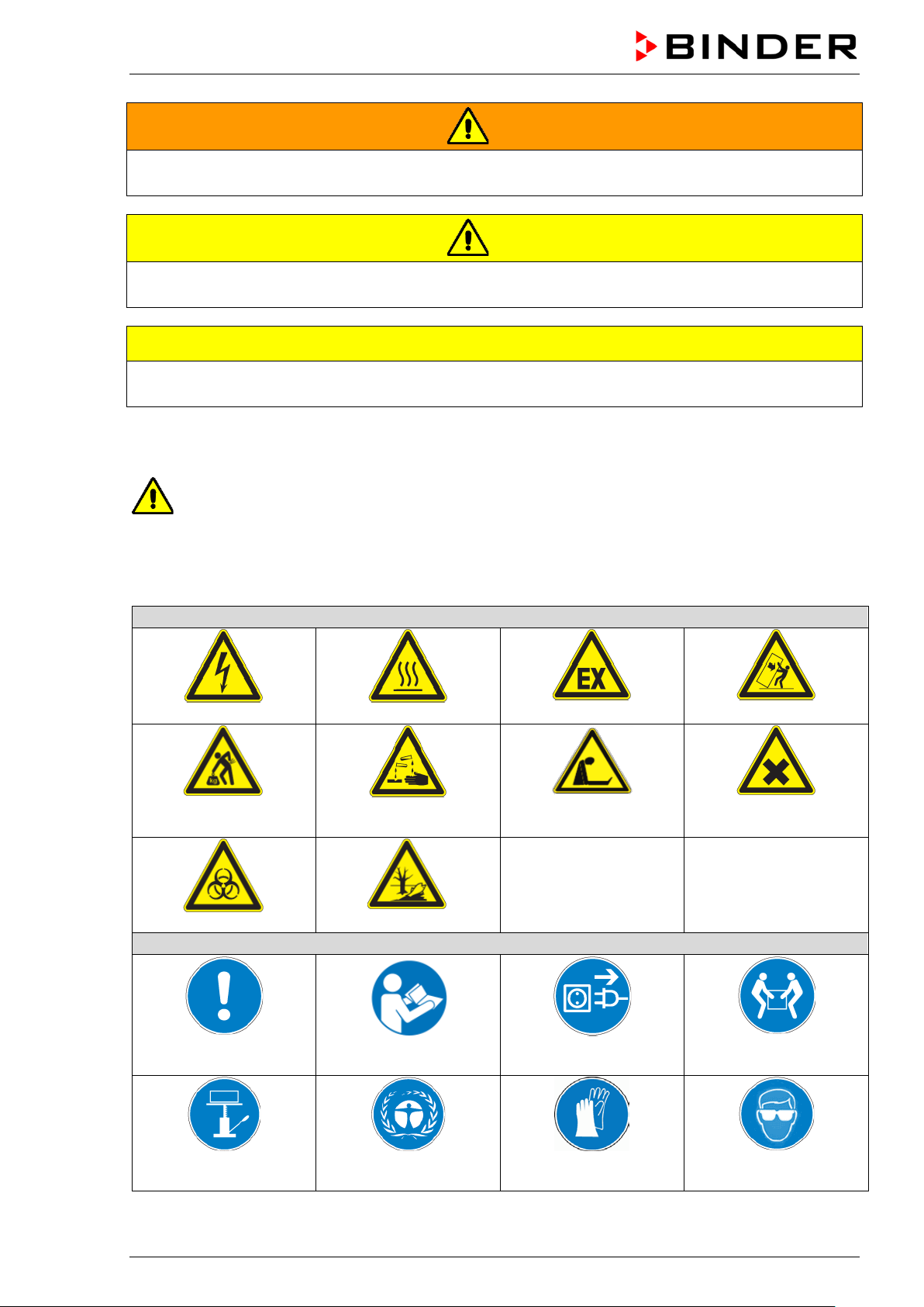
Warning signs
Electrical hazard
Hot surface
chemical burns
Biohazard
Mandatory action signs
instructions
plug
assistance
WARNING
Indicates a potentially hazardous situation which, if not avoided, could result in death or serious
(irreversible) injury
CAUTION
Indicates a potentially hazardous situation which, if not avoided, may result in moderate or minor
(reversible) injury
CAUTION
Indicates a potentially hazardous situation which, if not avoided, may result in damage to the product
and/or its functions or of a property in its proximity.
1.2.2 Safety alert symbol
Use of the safety alert symbol indicates a risk of injury.
Observe all measures that are marked with the safety alert symbol in order to avoid death or
injury.
1.2.3 Pictograms
Lifting hazard
Risk of corrosion and / or
Pollution Hazard
Explosive atmosphere
Suffocation hazard
Stability hazard
Harmful substances
Mandatory regulation
Lift with mechanical
BD / BF / ED / FD / FED (E3.1) 07/2017 page 6/99
Read operating
Environment protection Wear protective gloves
Disconnect the power
Lift with several persons
Wear safety goggles
Page 7

Prohibition signs
water
Pictograms (Warning signs)
Service label
Do NOT touch
Do NOT spray with
Information to be observed in order to ensure optimum function of the product.
1.2.4 Word message panel structure
Type / cause of hazard.
Possible consequences.
∅ Instruction how to avoid the hazard: prohibition.
Instruction how to avoid the hazard: mandatory action.
Observe all other notes and inf ormation not necessarily emphasi zed in the same way, in order to avoid
disruptions that could result in direct or indirect injury or property damage.
1.3 Localization / position of safety labels on the chamber
The following labels are located on the chamber:
Hot surface
• ED, FD, FED: outer chamber door
• BD, BF: on the glass door handle
• On chamber rear next to the exhaust duct
Read operating manual
• UL chamber: outer chamber door
• BD, BF with optional interior socket: below the
interior socket
BD / BF / ED / FD / FED (E3.1) 07/2017 page 7/99
ED, FD, FED
ED-UL, FD-UL, FED-UL
Figure 1: Position of labels on the chamber front (example: ED, FD, FED)
Page 8
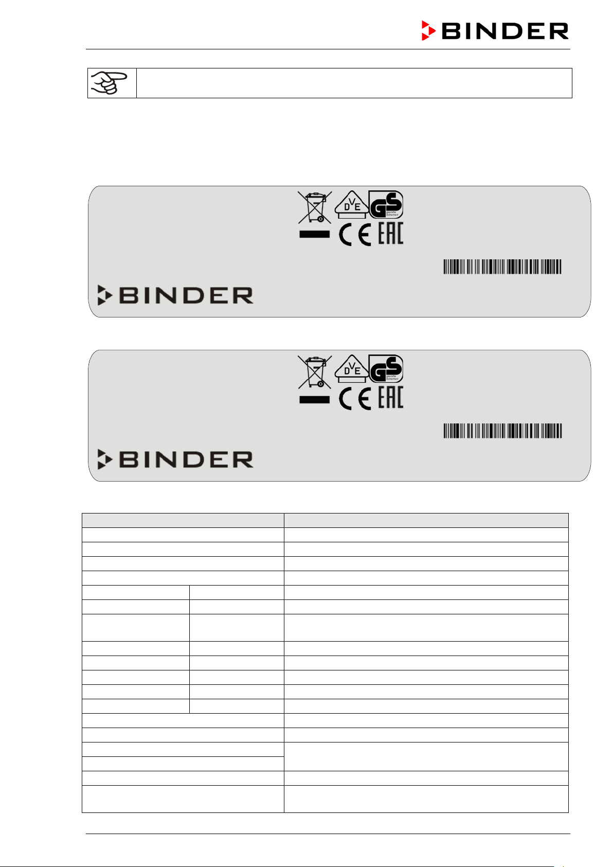
Indications of the type plate (example)
Information
BINDER
Manufacturer: BINDER GmbH
BD 115
Model designation
Incubator
Chamber name: Incubator
Drying and heating oven
Chamber name: Drying and heating oven
Serial No.
000000000000
Serial No of the chamber
Built
2017
Year of construction
100 °C
212 °F
IP protection
20
IP type of protection acc. to EN 60529
Temp. safety device
DIN 12880
Temperature safety device acc. to standard DIN 12880
Class
3.1
Class of temperature safety device
Art. No.
9110-0305
Art. no. of the chamber
Project No.
---
Optional: Special application acc. to project no.
1,30 kW
Nominal power
5,7 A
Nominal current
230 V / 50 Hz
230 V / 60 Hz
1 N ~
Current type
Nominal power: 0,85 kW
Nominal temp.
300 °C
1,30 kW / 5,7 A
572 °F
230 V / 50 Hz
IP protection
20
230 V / 60 Hz
Safety device
DIN 12880
1 N ~
Class
2.0
Art. No.
9010-0305
Project No.
Built
2017
Drying and heating oven
BINDER GmbH
www.binder-world.com
FED 115
E3.1
Serial No. 00000000000000
Nominal temp.
100 °C
0,35 kW / 1,6 A
With option internal socket:
212 °F
230 V / 50 Hz
Nominal power: 0,85 kW
IP protection
20
230 V / 60 Hz
Safety device
DIN 12880
1 N ~
Class
3.1
Art. No.
9110-0325
Project No.
Built
2017
Incubator
BINDER GmbH
www.binder-world.com
BD 115
E3.1
Serial No. 00000000000000
Keep safety labels complete and legible.
Replace safety labels that are no longer legible. Contact BINDER Service for these replacements.
1.4 Type plate
The type plate is located on the left-hand side of the chamber, bottom right-hand.
Im Mittleren Ösch 5
78532 Tuttlingen / Germany
Figure 2: Type plate (example FED 115-230V regular chamber)
Made in Germany
Nominal temperature
Im Mittleren Ösch 5
78532 Tuttlingen / Germany
Made in Germany
Figure 3: Type plate (example BD 115-230V optional chamber)
Nominal temperature
With option internal socket:
BD / BF / ED / FD / FED (E3.1) 07/2017 page 8/99
Nominal voltage ± 10%
at the indicated power frequency
With option internal socket: increased total nominal power
Page 9
Symbol on the type plate
Information
CE conformity marking
Electrical and electronic equipment manufactured / placed on
the market in the EU after 13 August 2005 and to be disposed of
in a separate collection according to Directive 2012/19/EU on
waste electrical and electronic equipment (WEEE).
The chamber is certified according to Customs Union Technical
Regulation (CU TR) for the Eurasian Economic Union (Russia,
Belarus, Armenia, Kazakhstan Kyrgyzstan).
GS mark of conformity of the “VDE Prüf- und Zertifizierungsinstitut” (Testing and Certification Institute of the Association for
Electrical, Electronic and Information Technologies
The chamber is certified by Underwriters Laboratories Inc.
®
ac-
cording to the following standards:
rd
(UL chambers only)
UL 61010-1, 3
CAN/CSA-C22.2 No. 61010-1, 3
IEC 61010-2-10 :2014, 3
Edition, 2012-05, rev. 2015-07
rd
rd
Edition
Edition, 2012-05, rev. 2015-07
1.5 General safety instructions on installing and operating the chambers
With regard to operating th e chambers and to the ins tallation location, ple ase observe the DGU V guidelines 213-850 on safe working in laboratories (formerly BGI/GUV-I 850-0, BGR/GUV-R 12 0 or ZH 1/119,
issued by the employers’ liability insurance association) (for Germany).
BINDER GmbH is only respons ible for the safety featur es of the chamber provided s killed electricians or
qualified personnel authorized by BIND ER perform all m aintenance and repair, and if components relating to chamber safety are replaced in the event of failure with original spare parts.
To operate the chamber, use only orig inal BINDER accessories or acc essories fr om third-part y suppliers
authorized by BINDER. The user is responsible for any risk caused by using unauthorized accessories.
CAUTION
Danger of overheating.
Damage to the chamber.
∅ Do NOT install the chamber in unventilated recesses.
Ensure sufficient ventilation for dispersal of the heat.
Do not operate the chambers in hazardous locations.
DANGER
BD / BF / ED / FD / FED (E3.1) 07/2017 page 9/99
Explosion hazard.
Danger of death.
∅ Do NOT operate the chamber in potentially explosive areas.
KEEP explosive dust or air-solvent mixtures AWAY from the chamber.
Page 10
glass doors and glass door han d les (BD, BF), inner chamber, exhaust duct, door
The chambers do not dispose of any measures of explosion protection.
DANGER
Explosion hazard.
Danger of death.
∅ Do NOT introduce any substance into the chamber which is combustible or explosive at
working temperature.
∅ NO explosive dust or air-solvent mixture in the inner chamber.
Any solvent contained in th e charging material m ust not be explosive or inflamm able. I.e., irrespect ive of
the solvent concentrati on in the steam room, NO explos ive mixture with air must f orm. The temperature
inside the chamber mus t lie below the flash point or below th e sublimation po int of the charging m aterial.
Familiarize yourself with the physical and chemical properties of the charging material, as well as the
contained moisture constituent and its behavior with the addition of heat energy.
Familiarize yourself with a ny potential health risks caused b y the charging material, the conta ined moisture constituent or b y reaction products that m ay arise during the temperature pr ocess. Take adequate
measures to exclude such risks prior to putting the chamber into operation.
DANGER
Electrical hazard.
Danger of death.
∅ The chamber must NOT become wet during operation or maintenance.
The chambers were produ ced in accordance with VDE regu lations and were routinel y tested in accordance to VDE 0411-1 (IEC 61010-1).
During and shortly after operation, the temperature of the inner surfaces almost equals the set-point.
CAUTION
The
window (option), and the door gaskets will b ecome hot during operation.
Danger of burning.
∅ Do NOT touch the glass doors, inner surfaces, exhaust duct, door window, access
ports, door gaskets, or the charging material during operation.
BD / BF / ED / FD / FED (E3.1) 07/2017 page 10/99
Page 11
1.6 Intended use
The chambers are suitable f or ex act tempering of harmless materials and for drying and heat tre at ment of
solid or pulverized c h argi ng material, as well as bu lk mater ia l, usin g th e s up ply of heat. They ca n b e used
to dry e.g. glassware, and for warm storage of liquids in containers.
Because of their precise temperature accuracy the incubators BD and BF are especially useful for incubation of cultures at a standard temperature of 37 °C / 98.6 °F.
A solvent content m ust not be ex plosi ve or flam m able. A m ixture of any componen t of the c harging m aterial with air must NOT be explosi ve. T he oper at ing te mperature must lie below the f lash poin t or below th e
sublimation point of the chargin g material. Any com ponent of th e charging m aterial mus t NOT be able to
release toxic gases.
Other applications are not approved.
The chambers are not classified as medical devices as defined by the Medical D evice Directive
93/42/EEC.
Do NOT use the chamber for drying proces ses when large quantities of vapor would form and result in
condensation.
Due to the special demands of the Medical Device Directive 93/42/EEC, these ovens are not
qualified for sterilization of medical devices as defined by the directive.
Observing the instructions in this operating manual and conducting regular maintenance work
(chap. 13) is part of the intended use.
WARNING: If customer should use a BINDER chamber running in non-supervised continuous operation, we strongly recommend in case of inclusion of irrecoverable specimen or
samples to split such specimen or samples and store them in at least two chambers, if this is
feasible.
The charging material shall not contain any corrosive ingredients that may damage the machine components. Such ingredients include in particular acids and halides. Any corrosive
damage caused by such ingredients is excluded from liability by BINDER GmbH.
The chambers do not dispose of any measures of explosion protection.
DANGER
Explosion or implosion hazard.
Danger of poisoning.
Danger of death.
∅ Do NOT introduce any substance combustible or explosive at working temperature into
the chamber, in particular no energy sources such as batteries or lithium-ion batteries.
∅ NO explosive dust or air-solvent mixture in the inner chamber.
∅ Do NOT introduce any substance which could lead to release of toxic gases.
In case of foreseeable use of the device there is no risk for the user through t he integration of the chamber into systems or by special environmental or operating conditions in th e sense of EN 61010-1:2010.
For this, the intended use of the chamber and all its connections must be observed.
Connect only external devi ces to the chamber interfaces Ether net (regular with FED, optional with BD,
BF, ED, FD) and USB which are compliant with the standards EN 61010-1:2010 or EN 60950-1:2006
mod.
BD / BF / ED / FD / FED (E3.1) 07/2017 page 11/99
Page 12

(2)
(3)
(1)
2. Chamber description
BINDER incubators BD a nd BF and drying and heating ovens ED, FD an d FED are equipped with an
electronic PID-contro ll er with digit al disp lay.
The incubators BD and BF indicate the temperature with an accuracy of a tenth of a degree.
The drying and heating ovens ED, FD and FED indicate the tem per atur e with an a c cur acy of
one degree.
All chambers are heated electricall y. Incubators BD a nd drying and he ating oven s ED are ventilated n aturally. Incubat ors BF and dr ying and hea ting o vens F D and FED are vent ilated by fan-assisted, forced-air
circulation.
The concept of air conduction guarantees high level of spatial and time-based temperature precision,
thanks to the direct and distr ibuted air circ ulation into the inter ior. W ith BF, F D an d FED , the f an su pports
exact attainment and maintenance of the desired temperature accur ac y.
The chambers are regularly equipped with an overtemperature safety device class 1 acc. to
DIN12880:2007 and with a n overtemperature safety controller (overtemperature temperatur e safety device class 2 or class 3.1 acc. to DIN12880:2007), see chap. 7).
The inner chamber and the inside of the d oors are made of stainless steel V2A (G erman material no.
1.4301, US equivalent AIS I 304 and m aterial no. 1.4016, US equiva lent AISI 430). Dr ying and heating
ovens ED, FD and FE D: When operatin g the chambers at tem peratures above 150 °C / 302 °F, the impact of the ox ygen in t he ai r may cause discoloratio n o f the metallic surfaces (yellowish-brown or blue) b y
natural oxidation processes. These colorations are harmless and will in no way impair the function or
quality of the chamber. The housing is RAL 703 5 powder-coated. All corners and ed ges are also completely coated.
All chamber functions are eas y and comfortable to use thank s to their cle ar arrangem ent. Major feat ures
are easy cleaning of all chamber parts and avoidance of undesired contamination.
The chambers ar e regularly (FED) or optionall y equipped with an Ethernet interf ace for computer communication, e.g. via the com munication software APT -COM™ 3 DataControlSystem (option, chap. 12.1)
and with a USB interface to read out the measured values in real time.
Temperature ranges see technical data (chap. 16.4 - 16.8).
2.1 Chamber overview
Figure 4: Overview, closed chamber
BD / BF / ED / FD / FED (E3.1) 07/2017 page 12/99
Page 13
(4)
(3)
(6)
(5)
(1)
(2)
(9)
(8)
(7)
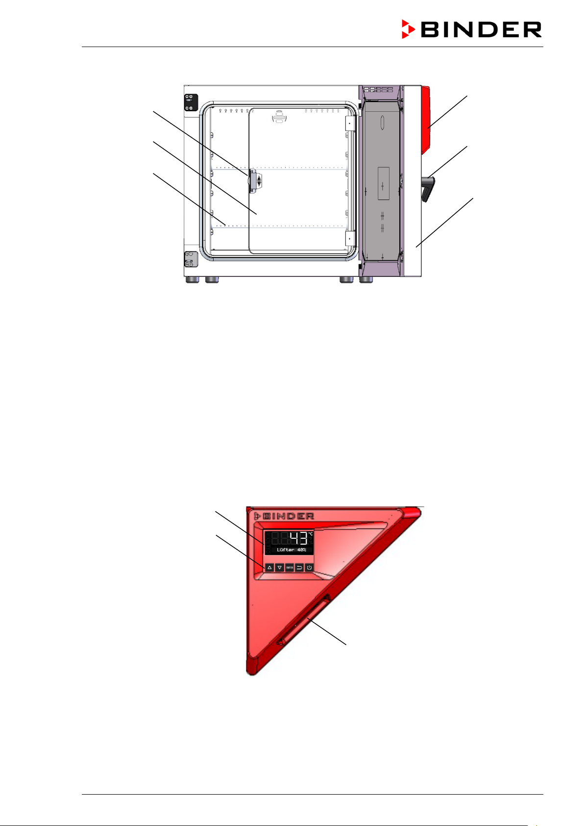
Figure 5: Overview, open chamber with glass door (BD, BF)
(1) Triangular instrument panel with controller R4 and USB interface
(2) Door handle
(3) Outer door
(4) Glass door handle (BD and BF)
(5) Glass door (BD and BF)
(6) Rack
2.2 Triangular instrument panel
Figure 6: Triangular instrument panel
(7) Controller display
(8) Functional controller buttons
(9) USB interface
BD / BF / ED / FD / FED (E3.1) 07/2017 page 13/99
Page 14
3. Completeness of delivery, transportation, storage, and installa-
tion
3.1 Unpacking, and checking equipment and completeness of delivery
After unpacking, p lease check the chamber and its optional accessories, if any, based on the delivery
receipt for completenes s and for transportation damage. Inf orm the carrier immediately if trans portation
damage has occurred.
The final tests of the m anufacturer m ay have caused trac es of the rack s on the inner surfac es. This has
no impact on the function and performance of the chamber.
Please remove any transportation pr otection devices and adhes ives in/on the chamber and on the doors
and take out the operating manuals and accessory equipment.
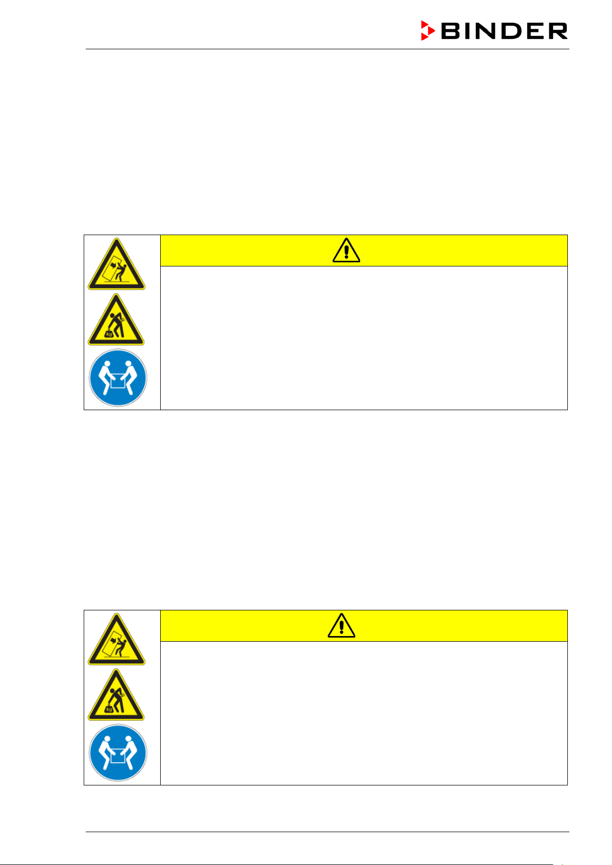
CAUTION
Sliding or tilting of the chamber.
Damage to the chamber.
Risk of injury by lifting heavy loads.
∅ Do NOT lift or transport the chamber using the door handle or the door.
Lift the chamber size 56 and 115 from the pallet at its four lower corners with the aid
of 2 people, chamber size 260 with the aid of 4 people.
If you need to return the chamber, pleas e use the original packing and o bserve the guidelines for safe
lifting and transportation (chap. 3.2).
For disposal of the transport packing, see chap. 14.1.
Note on second-hand chambers (Ex-Demo-Units):
Second-hand chambers are chambers that have been used f or a short time for tests or exhibitions. T hey
are thoroughly tested b efor e resale . BIND ER ens ures that the c ham ber is technic all y sound and will work
flawlessly.
Second-hand chambers are marked with a sticker on the chamber door. Please remove the stick er bef ore
commissioning the chamber.
3.2 Guidelines for safe lifting and transportation
After operation please observe the guidelines for temporarily decommissioning the chamber (chap. 14.2).
CAUTION
Sliding or tilting of the chamber.
Damage to the chamber.
Risk of injury by lifting heavy loads.
Transport the chamber only in its original packaging.
Secure the chamber with transport straps for transport.
∅ Do NOT lift or transport the chamber using the door handle or the door.
Lift chamber size 56 and 115 at its four lower corners with the aid of 2 people,
chamber size 260 with the aid of 4 people, and place it on a transport pallet with
wheels. Push the pallet to the desired site and then lift the chamber from the pallet at
its four lower corners.
• Permissible ambient temperature range during transport: -10 °C to +60 °C / 14 °F to 140 °F.
You can order transport packing and pallets for transportation purposes from BINDER Service.
BD / BF / ED / FD / FED (E3.1) 07/2017 page 14/99
Page 15
3.3 Storage
Intermediate storage of the chamber is possible in a closed and dry room . Observe the guidelines for
temporary decommissioning (chap. 14.2).
• Permissible ambient temperature range during storage: -10 °C to +60 °C / 14 °F to 140 °F.
• Permissible ambient humidity: max. 70 % r.H., non-condensing
When after storage in a co ld location you transfer the chamber to its warm er installation site, condens ation may form. Befor e start-up, wait at least one hour u ntil the chamber has attai ned am bient tem per ature
and is completely dry.
3.4 Location of installation and ambient conditions
Set up the chamber on an eve n and non-flammable sur face, free from vibration and i n a well-ventilated,
dry location and align it using a spirit level. The site of installation must be capable of supporting the
chamber’s weight (see technical data, chap. 16.4 to 16.7). The chambers are designed for setting up
inside a building (indoor use).
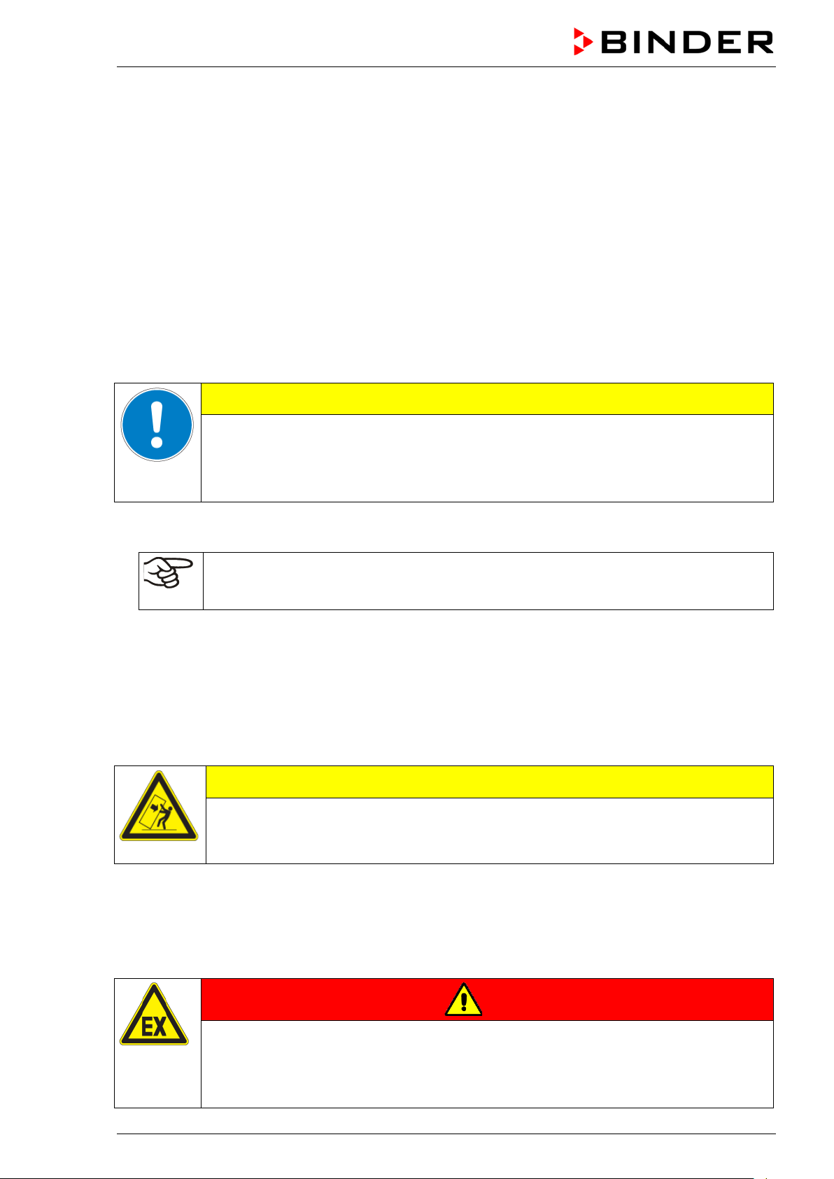
CAUTION
Danger of overheating.
Damage to the chamber.
∅ Do NOT set up chambers in non-ventilated recesses.
Ensure sufficient ventilation for dispersal of the heat.
• Permiss ible ambient temper ature range during oper ation: +18 °C up to +40 ° C / 64.4 °F to 104 °F. At
elevated ambient temperature values, fluctuations in temperature can occur.
The ambient temperature should not be substantially higher than the indicated ambient
temperature of +25 °C / 77 °F to which the specified technical data relate. For other ambient conditions, deviations from the indicated data are possible.
• Permissible ambient humidity: 70 % r.H. max., non-condensing.
• Installation height: max. 2000 m / 6562 ft. above sea level.
When placing several chambers of the sam e size side b y side, m aintain a m inim um distance of 250 mm /
9.84 in between each chamber. W all distances: rear 160 mm / 6.30 in, sides 100 mm / 3.94 in. Spacing
above the chamber of at least 100 mm / 3.94 in must also be accounted for.
Two devices up to si ze 115 can be stac ked on t op of each ot her. For t his purpos e place r ubber pads u nder all four feet of the upper chamber to prevent the device from slipping.
CAUTION
Sliding or tilting of the upper chamber.
Damage to the chambers.
When stacking, place rubber pads under all four feet of the upper chamber.
To completely separat e the chamber from the power supp ly, you mus t disconnect the power plug. Install
the chamber in a way that the po wer p lug is e asil y acc essible and can b e eas il y pulled in cas e of danger .
Do not conduct the power cable above the exhaust duct.
For the user there is no risk of temporary overvoltages in the sense of EN 61010-1:2010.
Do not install or operate the chamber in potentially explosive areas.
DANGER
Explosion hazard.
Danger of death.
∅ Do NOT operate the chamber in potentially explosive areas.
KEEP explosive dust or air-solvent mixtures AWAY from the vicinity of the chamber.
BD / BF / ED / FD / FED (E3.1) 07/2017 page 15/99
Page 16

4. Installation
4.1 Mounting the tilt protection holders (chambers with window)
For chambers equipped with the option „door with window“ it is recommended to insta ll the supplied tilt
protection.
Scope of delivery of tilt protectio n kit (Art.no. 8009-0870):
• 2 screws
• 2 tilt protection holders
Preparing the tilt protection holders
• Depending on the desired wall distance, you can bend the tilt protection holders acc ording ly.
Figure 7: Variable length of the tilt protection holder depending on the bend
Installation on the chamber
• Plug the two tilt protec tion hol ders eac h with the tab on the provided spot on the edge of the rear pan-
el. The screw holes in the rear wall and in the tilt protection holders must align.
• Fix the tilt protection holders each with one of the supplied screws on the chamber rear wall.
Wall mounting
• Then fix both tilt protection holders on the wall, each with 2 screws Ø 6mm suitable for the wall (B)
BD / BF / ED / FD / FED (E3.1) 07/2017 page 16/99
Page 17

FED056-230V
ED115-230V
FED115-230V
FED260-230V
ED056UL-120V
FED056UL-120V
FD115UL-120V
ED260UL-240V
FED260UL-240V
4.2 Electrical connectio n
The chambers are supplied ready for connection and come with an IEC connector plug.
Model
BD056-230V
BF056-230V
ED056-230V
FD056-230V
BD115-230V
BF115-230V
FD115-230V
BD260-230V
BF260-230V
ED260-230V
FD260-230V
BD056UL-120V
BF056UL-120V
FD056UL-120V
Power plug of the
power cable
Shockproof plug
Shockproof plug
Shockproof plug
Shockproof plug
Shockproof plug
Shockproof plug
NEMA 5-15P
NEMA 5-15P
Nominal voltage +/- 10% at the
indicated power frequency
230 V at 50 Hz
230 V at 60 Hz
230 V at 50 Hz
230 V at 60 Hz
230 V at 50 Hz
230 V at 60 Hz
230 V at 50 Hz
230 V at 60 Hz
230 V at 50 Hz
230 V at 60 Hz
230 V at 50 Hz
230 V at 60 Hz
115 V at 50 Hz
115 V at 60 Hz
115 V at 50 Hz
115 V at 60 Hz
Current
type
Chamber
fuse
1N~ 6,3 A
1N~ 6,3 A
1N~ 6,3 A
1N~ 6,3 A
1N~ 8,0 A
1N~ 12,5 A
1N~ 12,5 A
1N~ 12,5 A
BD115UL-120V
BF115UL-120V
ED115UL-120V
FD115UL-120V
BD260UL-120V
BF260UL-120V
FD260UL-240V
NEMA 5-15P
NEMA 5-15P
NEMA 5-15P
NEMA 6-20P
115 V at 50 Hz
115 V at 60 Hz
115 V at 50 Hz
115 V at 60 Hz
115 V at 50 Hz
115 V at 60 Hz
240 V at 50 Hz
240 V at 60 Hz
1N~ 12,5 A
1N~ 12,5 A
1N~ 12,5 A
2~ ---
• The dom estic socket must also prov ide a protective conduct or. Make sure that the connection of the
protective conductor of the domestic installations to the chamber’s protective conductor meets the
latest technology. The protective conductors of the socket and plug must be compatible!
• Prior to connection and start-up, check the power su ppl y voltag e. Com pare t he values to the s pecif ied
data located on the chamber’s type plate (left-hand side of the chamber, chap. 1.4).
• When connecting, please observe the regulations specified by the local electricity supply company
and as well as the VD E directives (for Germ any). We recommend the us e of a residua l current circ uit
breaker.
• Only use original connection cables from BINDER.
• Pollution degree (acc. to IEC 61010-1): 2
• Over-voltage category (acc. to IEC 61010-1): II
BD / BF / ED / FD / FED (E3.1) 07/2017 page 17/99
Page 18
CAUTION
Danger of incorrect power supply voltage.
Damage to the equipment.
Check the power supply voltage before connection and start-up.
Compare the power supply voltage with the data indicated on the type plate.
See also electrical data (chap. 16.4 to 16.7).
To completely separate the chamber from the power supply, you must disconnect the power
plug. Install the chamber in a way that the power plug is easily accessible and can be easily
pulled in case of danger.
4.3 Connection to a suction plant (optional)
When directly connectin g a suction plant the spatial temper ature exactitude, the heating-up a nd the recovering times and the m aximum temperature will be negativ ely influenced. So no suction p lant sho ul d be
directly connected to the exhaust duct.
Active suction from the chamber must only be effected together with extraneous air. Perforate
the connecting piece to the suction device or place an exhaust funnel at some distance to the
exhaust duct.
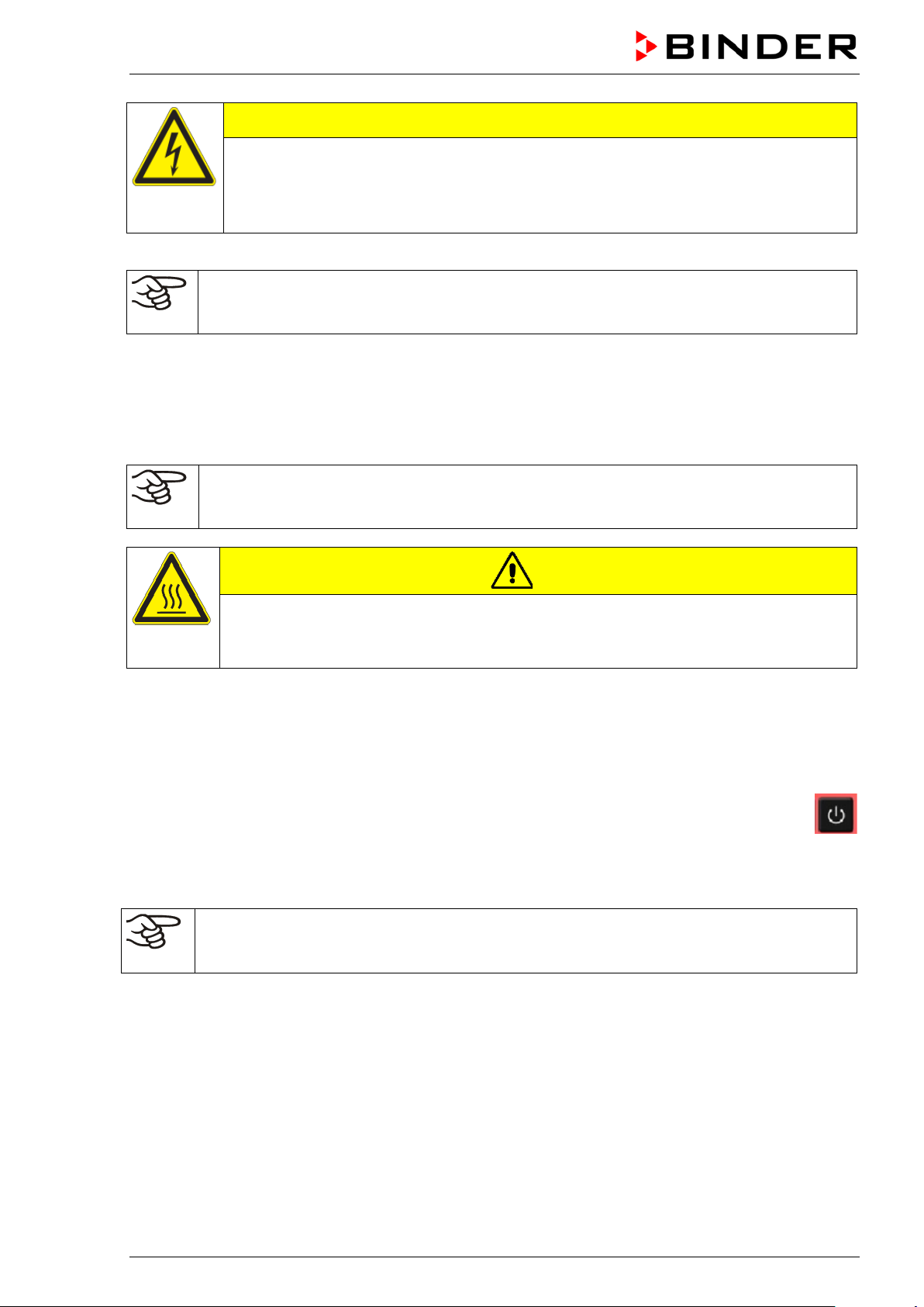
CAUTION
The exhaust duct will become hot during ope ration.
Danger of burning.
∅ Do NOT touch the exhaust duct during operation.
5. Start up
Insert the plug into a suitable socket (chap. 4.2).
If there is no other indicati on on the controller than the s tandby symbol, press th e standby button
until the display lights up.
The controller no w shows normal disp lay (chap. 6.2). If a timer function was active pri or to turn ing off the
chamber, it is shown in the controller display.
Warming chambers may release odors in the first few days after commissioning. This is not a
quality defect. To reduce odors quickly we recommend heating up the chamber to its nominal
temperature for one day and in a well-vent ilat ed loc at io n.
5.1 Behavior when opening the door
BD, ED: Depending on the temperature, heating performance may be adapted when opening the door.
BF, FD, FED: When opening the door, heating and fan turn off as long as the door remains open.
BD / BF / ED / FD / FED (E3.1) 07/2017 page 18/99
Page 19
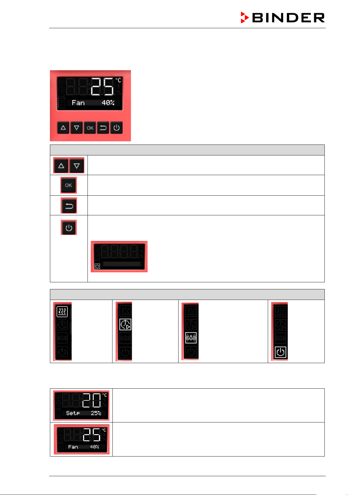
6. Overview and general settings on the R4 controller
6.1 Controller overview
Buttons on the controller
The arrow buttons serve to navigate and to enter the values
The OK button serves to select the parameters and to confirm the entered values
The Back button serves to reach the preceding level
If the Standby button is pressed down for approx. 3 seconds, the display changes to
standby mode. To activate the display, press down the standby button again for approx.
3 seconds
Display in standby mode with standby symbol
Status symbols on the controller display
Heating
active
Timer
operation
Overtemperature
alarm of the safety
controller
Standby
mode
6.2 Normal display
Normal display with chambers without fan (BD, ED)
or with fixed fan speed (FD)
Normal display with chambers with adjustable fan speed (BF, FED)
BD / BF / ED / FD / FED (E3.1) 07/2017 page 19/99
Page 20
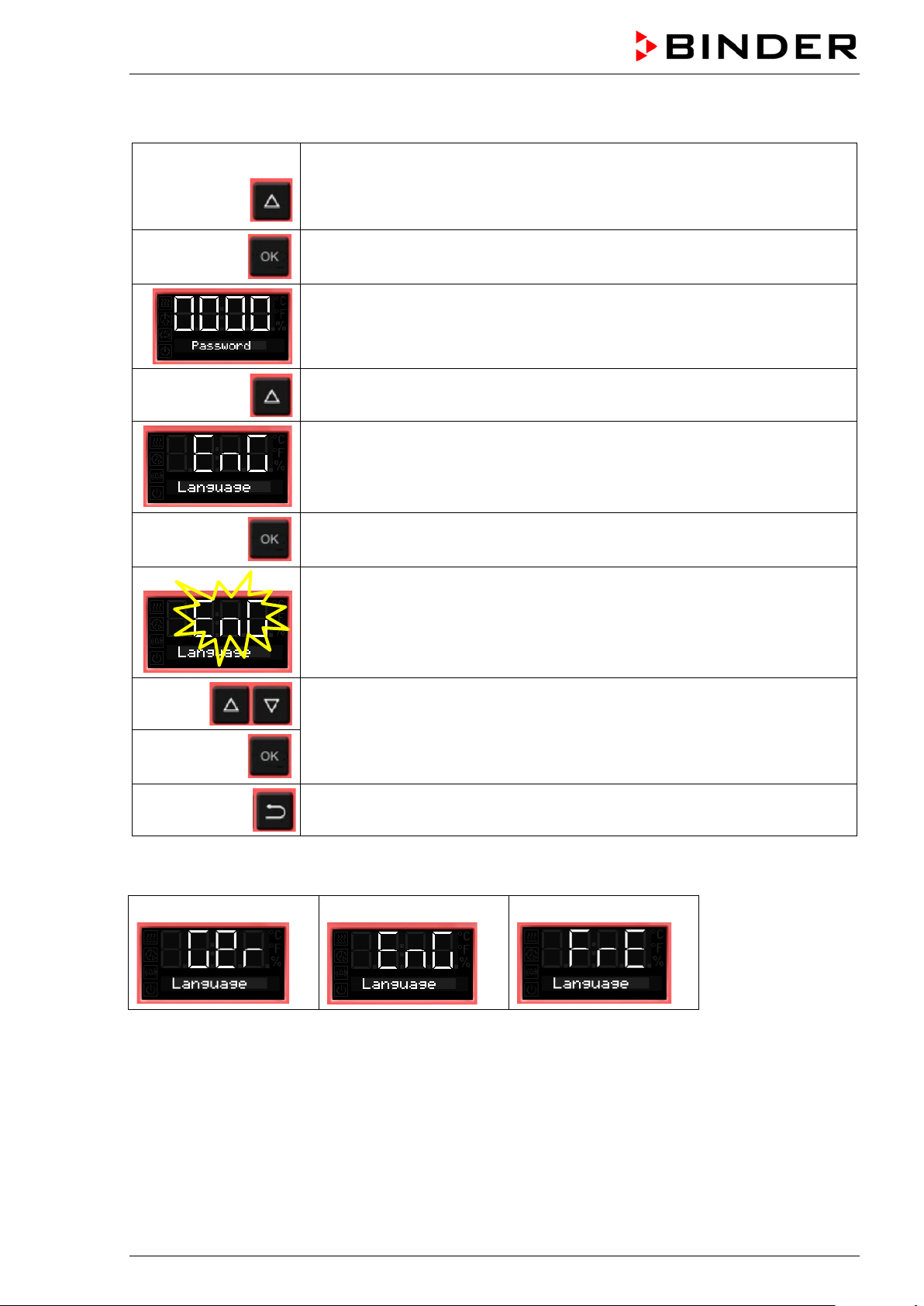
6.3 Setting the menu language
From Normal display
without fan 5x
with fan 6x
4 x
with the arrow-up button to the user menu
Confirm with OK.
Enter the password (factory setting: 00 00)
and confirm each entry with OK.
with the arrow-up button to the language setting menu.
The current menu language is shown.
Press OK to select the menu language.
The setting flashes.
Select the setting with the arrow buttons
and confirm with OK.
2x
There are the following options:
German:
Back to Normal display.
English:
French:
BD / BF / ED / FD / FED (E3.1) 07/2017 page 20/99
Page 21

6.4 Setting date and time
From Normal display
without fan 5x
with fan 6x
with the arrow-up button to the user menu
Confirm with OK.
Enter the password (factory setting: 00 00)
and confirm each entry with OK.
The current date is shown.
Press OK to set the year.
The setting flashes.
Enter the year with the arro w buttons (any setting)
and confirm with OK.
Press OK to set the month.
The setting flashes.
Enter the month with arr o w buttons (1 to 12)
and confirm with OK.
Without the optional real time clock, these settings must be repeated when the power supply is
interrupted..
BD / BF / ED / FD / FED (E3.1) 07/2017 page 21/99
Page 22

Press OK to set the day.
The setting flashes.
Enter the day with arrow buttons (1 to 31)
and confirm with OK.
Press OK to set the hour.
The setting flashes.
Enter the hour with arrow buttons (0 to 23)
and confirm with OK.
Press OK to set the minute.
The setting flashes.
Enter the minute with arrow buttons (0 to 59)
and confirm with OK.
2x
Back to Normal display.
BD / BF / ED / FD / FED (E3.1) 07/2017 page 22/99
Page 23
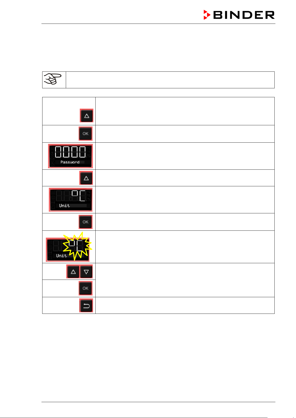
6.5 Selecting the temperature unit
You can chose between degrees Celsius °C and degrees Fahrenheit °F.
If the unit is changed, the temperature set-point and limits are converted accordingly.
Also when specifying the ramp function (see chap. 9) this setting is accordingly taken as the basis.
C = degrees Celsius
F= degrees Fahrenheit
without fan 5x
with fan 6x
0 °C = 31°F
100 °C = 212°F
From Normal display
with the arrow-up button to the user menu
Confirm with OK.
Enter the password (factory setting: 00 00)
and confirm each entry with OK.
With the arrow-up button to the temperature unit selection menu.
The current temperature unit is shown.
Conversion:
[Value in °F] = [Value in °C] ∗ 1.8 + 32
Press OK to select the temperature unit.
The setting flashes.
Select the setting with arrow buttons
and confirm with OK.
2x
Back to Normal display.
BD / BF / ED / FD / FED (E3.1) 07/2017 page 23/99
Page 24
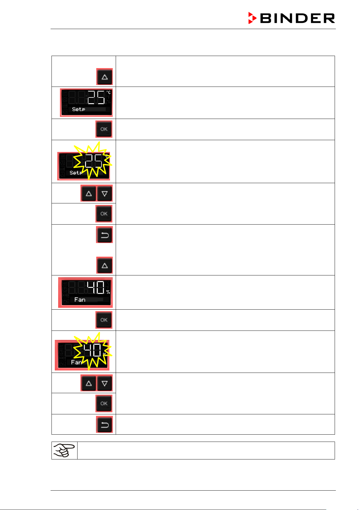
6.6 Set-point entry for temperature and fan speed
From Normal display
with the arrow-up button to the Set-point entry menu.
The current temperature set-point is displayed.
Press OK to enter the temperature set-point.
The temperature set-point flashes.
Enter the temperature set-po int wit h arr o w buttons with an accuracy of a tenth
of a degree (BD, BF) or of one degree (ED, FD, FED)
or
and confirm with OK.
Back to Normal display.
with chambers with adjustable fan speed (BF, FED):
go on to enter the fan speed.
The fan speed set-point is displayed.
Press OK to enter the fan speed
The fan speed set-point flashes
Adjust the fan speed in steps of 10 % with arrow buttons
and confirm with OK.
Back to Normal display.
Check and/or adjust the safety controller following any changes of the set-point (chap. 7).
BD / BF / ED / FD / FED (E3.1) 07/2017 page 24/99
Page 25
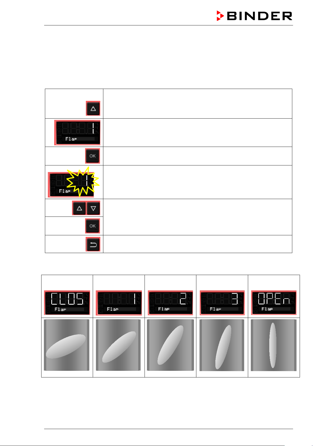
6.7 Adjusting the air flap position
Opening the air flap in the exhaust duct serves to adjust the air change.
The position of the air f lap in the exhaust duct serv es to adjust the fresh air entry. With the open th e air
flap, fresh air can enter through the fresh air tube. For chambers with fan, fan operation will increase
fresh air entry.
If the air flap is completely open, the spatial temperature accuracy can be negatively influenced.
From Normal display
without fan 2x
with fan 3x
with the arrow-up button to the Adjusting the air flap position menu.
The current air flap position is shown.
Press OK to select the air flap position.
The setting flashes.
Select the position with arrow buttons
and confirm with OK.
Back to Normal display.
There are the following options:
Air flap
closed
The setting can be done in steps of 15°.
Air flap slightly
opened
Air flap half opened
Air flap almost
open
Air flap open
BD / BF / ED / FD / FED (E3.1) 07/2017 page 25/99
Page 26

6.8 Changing the passwords for user level and general controller functions
In this menu you can change the passwords for access to the user menu and to all controller functions.
You can set two passworts for different access levels:
L1 (level 1): The password enables access control to the user level
L2 (level 2): The password enables access control to all controller functions
Factory setting for both passwords is 00 00 (no password assigned).
As soon as a password has been assigned, ac cess to the res pective functions is blocked and onl y avail-
able after enering the correct password.
From Normal display
without fan 5x
with fan 6x
2 x
with the arrow-up button to the user menu
Confirm with OK.
Enter the password (factory setting: 00 00)
and confirm each entry with OK.
With the arrow-up button to the password setting menu.
Password L1 for access to the user level.
Confirm with OK.
The current password level L1
is shown. The setting flashes.
You can change beween L1
and L2 with arrow buttons.
Select the setting with arrow
buttons (if desired)
and confirm with OK.
The current password for the selected password level is shown. The left two
digits are flashing.
Enter the desired numbers with arrow buttons,
confirm with OK and go on.
BD / BF / ED / FD / FED (E3.1) 07/2017 page 26/99
Page 27
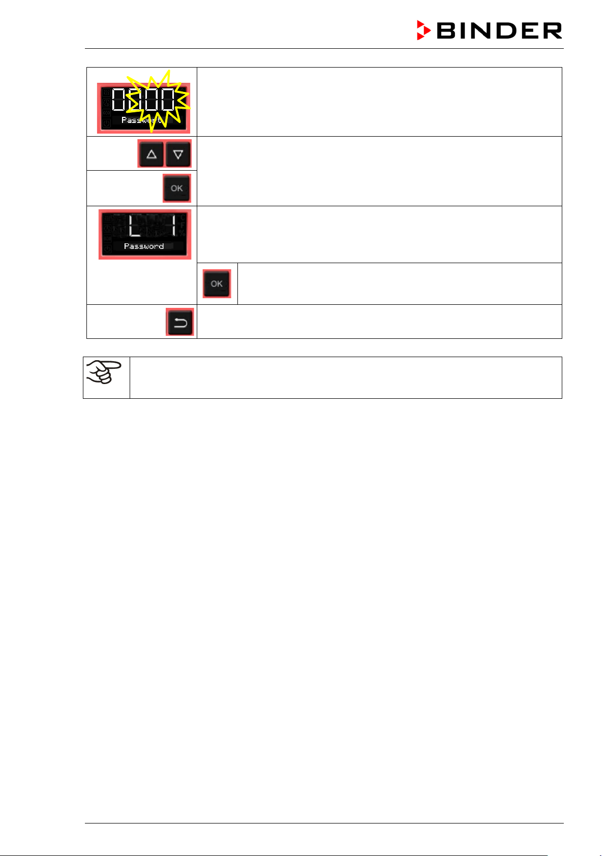
The right two digits of the password are flashing.
Enter the desired numbers with arrow buttons
and confirm with OK.
The modified password (L1 or L2 depending on the selection) is shown
(example: L1).
If you want to change beween L1 and L2, confirm with OK. Thereafter you can change to the other password level and also modify the
password.
2x
Keep in mind any modification of the password. There is no access to the user menu without
the correct password L1. Without the correct password L2 access control to all controller functions is blocked.
Back to Normal display.
BD / BF / ED / FD / FED (E3.1) 07/2017 page 27/99
Page 28
7. Overtemperature protection
7.1 Overtemperature protective device (class 1)
The chambers are regularl y equipped with an overtemperature protect ive device (safety device class 1
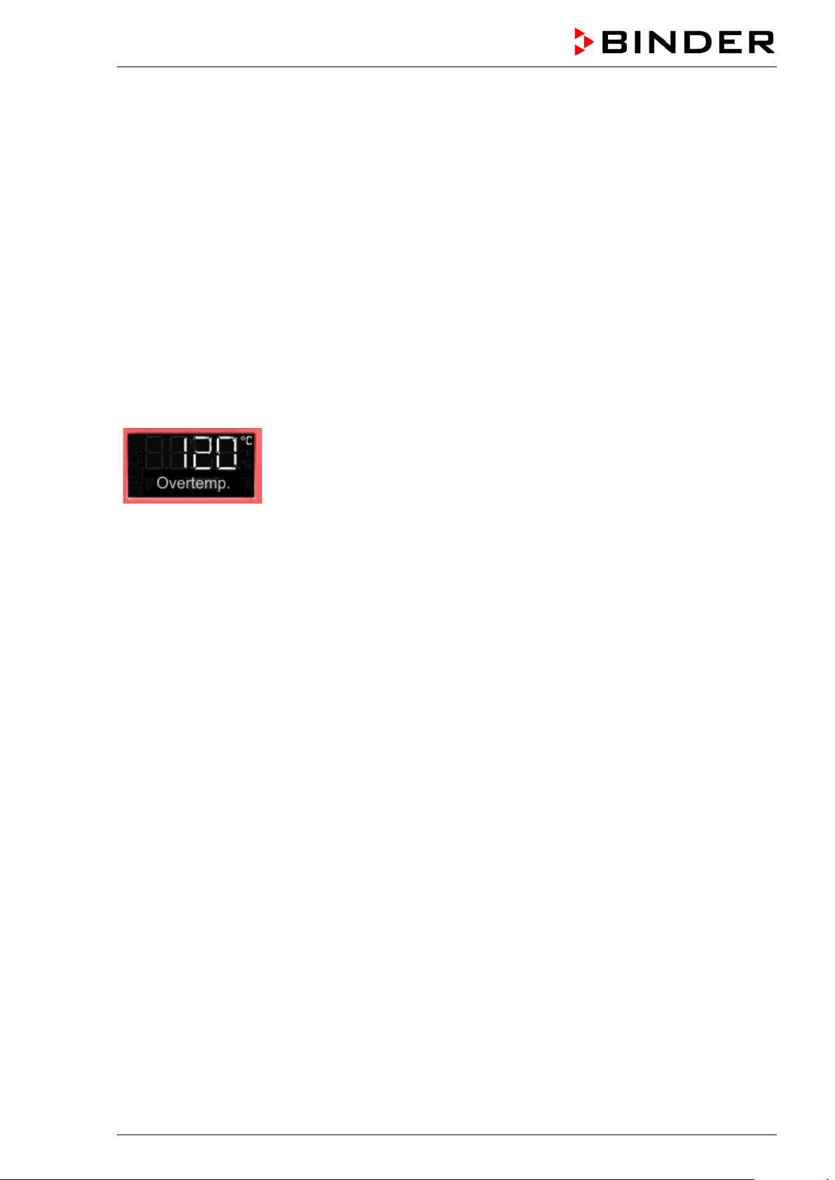
acc. to DIN 12880:2007). I t serves to protect t he chamber, its enviro nment and the contents a gainst exceeding the maxim um permissible temperature. When a defined tem per ature is reac hed, whic h is approx.
by 20 °C to 30 °C above the c hamber’s nominal tem peratur e, t he ov er temperature protective d evic e tur ns
off the heating.
Cut-off temperature values:
BD, BF: 120 °C
ED 260: 320 °C
ED 56, ED 115, FD 56, FED 56: 330 °C
FD 115, FD 260, FED 115, FED 260: 350 °C
The message “Overtemperature” is displayed on the controller.
If the overtemperature protective device class 1 has turned off the heating, proceed as follows:
• Disconnect the chamber from the power supply for at least 10 seconds (pull the power plug).
• If appropriate, have an expert examine and rectify the cause of the fault.
• Let the chamber cool down
• Restart the chamber.
As soon as the inner cham ber temperature after restart is below the defined cut-off temperature of the
overtemperature protective device class 1, the alarm message is deleted automatically.
Reset temperature values:
BD, BF: 90 °C
ED 260: 220 °C
ED 56, ED 115, FD 56, FED 56: 230 °C
FD 115, FD 260, FED 115, FED 260: 250 °C
BD / BF / ED / FD / FED (E3.1) 07/2017 page 28/99
Page 29

7.2 Safety controller
The chambers ar e regularly equipped with an adjustable electronic saf ety controller. It serves to protect
the chamber, its en vironm ent and t he co ntents against exceeding the m ax imum perm issible tem perature.
Please observe the DGUV gui del in es 213-850 on safe working in lab orator i es ( f ormerly BGI/GUV-I 850-0,
BGR/GUV-R 120 or ZH 1/119, issued by the employers’ liability insurance association) (for Germany).
Depending on the cham ber type the safety controller acts as an over temperature s afety device class 2
(“temperature limiter”) or class 3.1 (“temperature protection”) acc. to DIN 12880:2007.
Check the setting regularly and adjust it following any changes of the set-point.
• Safety controller class 2 (“temperature limiter”) with ED, FD and FED
The safety controller class 2 lim its the tem perature ins ide the cham ber to the ent ered safet y controller
set-point. In the event of a fault (if this maxim um temperature is exceede d) the safety contro ller completely turns of f the heating unti l manual reset. This s tatus is reported visually by an alarm message
and, in case of the option aud ible alarm with activated buzzer (chap. 7.6) additionally by the buzzer
sounding.
If the safety controller class 2 has turned off the heating, we recommend proceeding as follows:
• Disconnect the chamber from the power supply.
• Have an expert examine and rectify the cause of the fault.
• Restart the chamber
• Reset the alarm message
• Safety contro ller class 3.1 (“temperature protection”) with BD and BF
The safety controller class 3.1 limits the tem perature i nside the cham ber to the enter ed safet y controller set-point. In the event of a fault (if this maxim um tem per ature is exc eeded), it takes over the c ontro l
to this value. T his status is reported v isually by an alarm message and, in case of the option audible
alarm with activated buzzer (chap. 7.6) additionally by the buzzer sounding.
The safety controller k eeps control of the cham ber until the chamber temperatur e cools down below
the safety controller set-point value.
If the safety controller class 3.1 has taken over control, we recommend proceeding as follows:
• Disconnect the chamber from the power supply.
• Have an expert examine and rectify the cause of the fault.
• Restart the chamber
• Reset the alarm message
Function check:
Check the safety contro ller at ap propriat e inter vals f or i ts func tionalit y. It is r ecom m ended that the aut horized operating personnel should perform such a check, e.g., before starting a longer work procedure.
BD / BF / ED / FD / FED (E3.1) 07/2017 page 29/99
Page 30

7.3 Setting the safety controller set-point
A limit temp erature is entered as the safety controller set-point , i.e. the absol ute maximum permitted
temperature value.
Example: Temperature set-point 45 °C, safety controller set-point 50 °C.
Regularly check the safety controller setting relating to the entered temperature set-point
Set the safety controller set-point by approx. 2 °C to 5 °C above the desired temperature set-
point.
From Normal display
without fan 4x
with fan 5x
with the arrow-up button to the Safety controller set-point setting menu.
The current safety controller set-point is shown
(class 2 “temperature limiter” or class 3.1 “temperature protection” depending
on the chamber type).
Press OK to enter the safety controller set-point.
The safety controller set-point flashes.
Enter the safety controller set-point with arrow buttons:
10 °C up to 100 °C (with an accuracy of a tenth of a degree) with BD, BF
10 °C up to 300 °C (with an accuracy of one degree) with ED, FD, FED
and confirm with OK.
Back to Normal display.
BD / BF / ED / FD / FED (E3.1) 07/2017 page 30/99
Page 31

!TProt
7.4 Alarm message and proceeding in case of an alarm
The alarm icon flashes in the displ a y. In c ase of the option audible alarm with activated buzzer (chap. 7.6)
the buzzer sounds.
• Safety controller class 2 (“temperature limiter”)
The alarm icon flashes in t he displa y. In case of the o ption aud ible a larm with activated buzzer (chap.
7.6) the buzzer sounds.
The heating turns off.
Resetting the alarm:
With option audible alarm with activated buzzer: Mut e the buzzer pr es sing the OK button.
As soon as the inner c ham ber tem peratur e has c oole d down b elow th e saf ety c ontroller s et -poi nt, the
alarm icon is lit perm anently. You can reset the alar m m essage on the contr oller . To do this, reset the
alarm message in the safet y controller menu with the OK button. The heat ing is released and temperature control is resumed by the controller.
• Safety controller class 3.1 (“temperature protection”)
The alarm icon flas hes in t he displa y. In cas e of the option a udible alarm with activated buzzer (chap.
7.6) the buzzer sounds.
The heating turns off.
Resetting the alarm:
With option audible alarm with activated buzzer: Mute the buzzer pressing the OK button.
As soon as the inner chamber temperature has cooled down below the safety controller set-point,
You can reset the alarm message in the saf ety contro ller m enu with t he OK butt on, T he heat ing is released and temperature control is resumed by the controller.
Note:
When the safety contr oller class 2 or class 3.1 had been activated, you should disc onnect the chamber
from the power supply and have an expert examine and rectify the cause of the fault.
7.5 Function check
Check the temperature saf ety device c lass 2 or cl ass 3.1 at appropriate intervals f or its functional ity. It is
recommended that the a uthori zed operati ng personn el shou ld perfor m such a c heck, e.g., bef ore starti ng
a longer work procedure
BD / BF / ED / FD / FED (E3.1) 07/2017 page 31/99
Page 32
7.6 Disconnectable audible over-temperature alarm (option)
This option permits activating an audible signal:
If the buzzer is acti vated, a n audible s ignal soun ds when th e lim it temper ature set at t he safet y controll er
is exceeded. This happens in addition to the alarm message on the controller display.
Turning off the audible alarm does not influence the safety controller’s function.
From Normal display
without fan 5x
with fan 6x
5 x
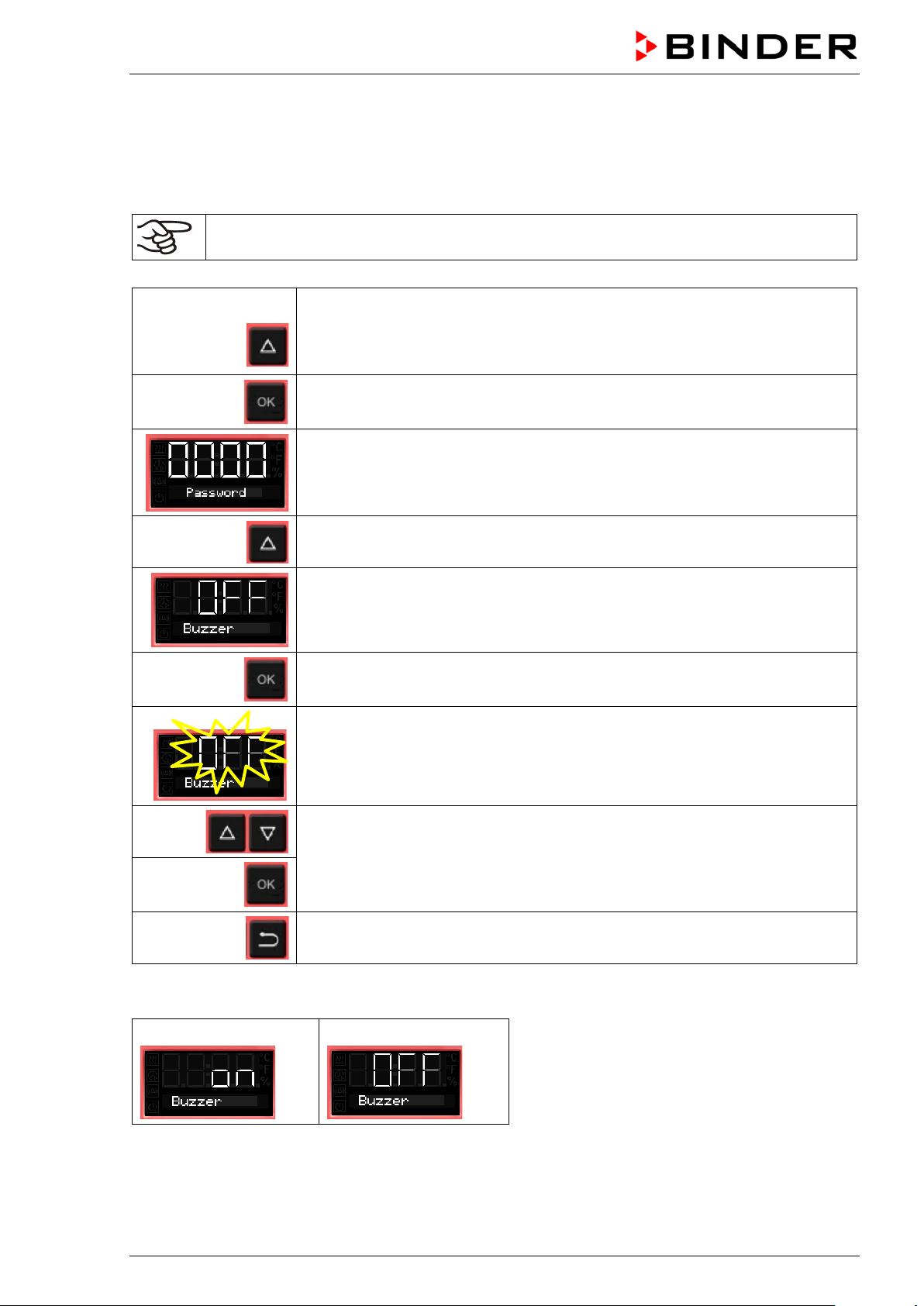
with the arrow-up button to the user menu
Confirm with OK.
Enter the password (factory setting: 00 00)
and confirm each entry with OK.
With the arrow-up button to the alarm buzzer setting menu
The current setting is shown.
Press OK to select the alarm buzzer setting
The setting flashes.
Select the setting with arrow buttons
and confirm with OK.
Back to Normal display.
There are the following options
Alarm buzzer On
BD / BF / ED / FD / FED (E3.1) 07/2017 page 32/99
Alarm buzzer Off
Page 33

BF, FED)
8. Timer functions
8.1 Selecting the timer function
There are up to three 3 timer functions:
Timer function “Delayed Off”
The selected timer run-time immediately starts running down.
When the timer expires the heating turns off. Chambers with fan: The fan may
continue working according to the selections made.
The chambers BD, ED and FD offer the timer function “Delayed Off”
The chambers BF and FED offer all the three timer functions.
Stage Heating
Timer function “Delayed Off”
Timer running
After the timer
expired
Timer function “Temperature dependent Delayed Off”
The selected timer run-time only starts running down, when the actua l val ue
reached or exceeds the selected set-point. When the timer expires the heating
turns off. Chambers with fan: The fan may continue working according to the
selections made.
Timer function “Delayed On”
The selected timer run-time immediately starts running down, the heating turns
off. Chambers with fan: The fan may be working according to the selections
made.
When the timer expires the heating turns on and remains in continuous operation.
Fan (Chamber with
fixed fan speed: FD)
Control to the
temperature set-point
Off
On (100 %)
On (100 %) or Off
(0 %) acc. to selection
Fan (Chambers with
adjustable fan speed:
Rotation speed according
to fan speed set-point
Rotation speed according
to setting of timer function
Timer function “Temperature dependent Delayed Off”
Possibly heatingup phase until the
temperature setpoint is reached
Timer running
After the timer
expired
Timer function “Delayed On”
Timer running
After the timer
expired
Control to the
temperature set-point
Control to the
temperature set-point
Off ---
Off --Control to the
temperature set-point
---
---
---
Rotation speed according
to fan speed set-point
Rotation speed according
to fan speed set-point
Rotation speed according
to setting of timer function
Rotation speed according
to setting of timer function
Rotation speed according
to fan speed set-point
BD / BF / ED / FD / FED (E3.1) 07/2017 page 33/99
Page 34
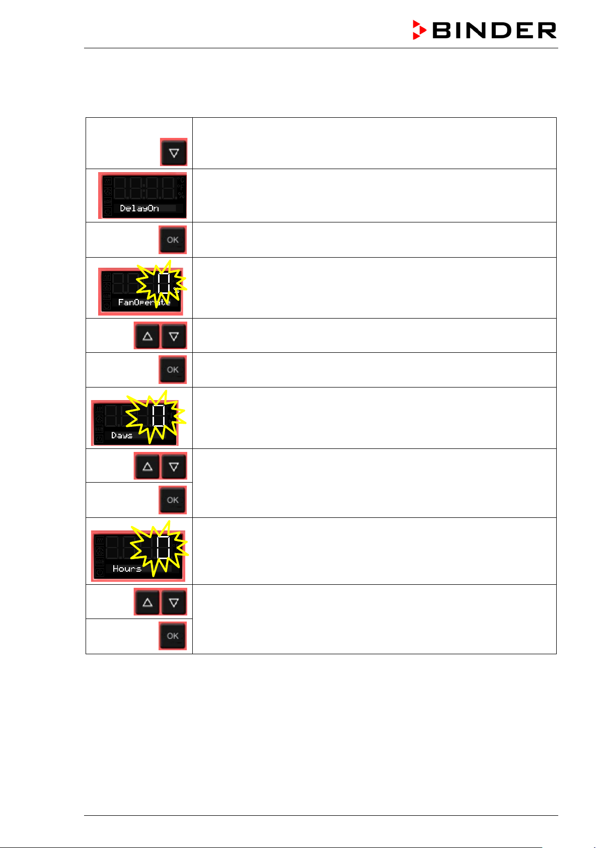
General information on the setting:
In the setting menus of the timer functions, it is always required to confirm all parameters with OK, otherwise all entries made will be lost.
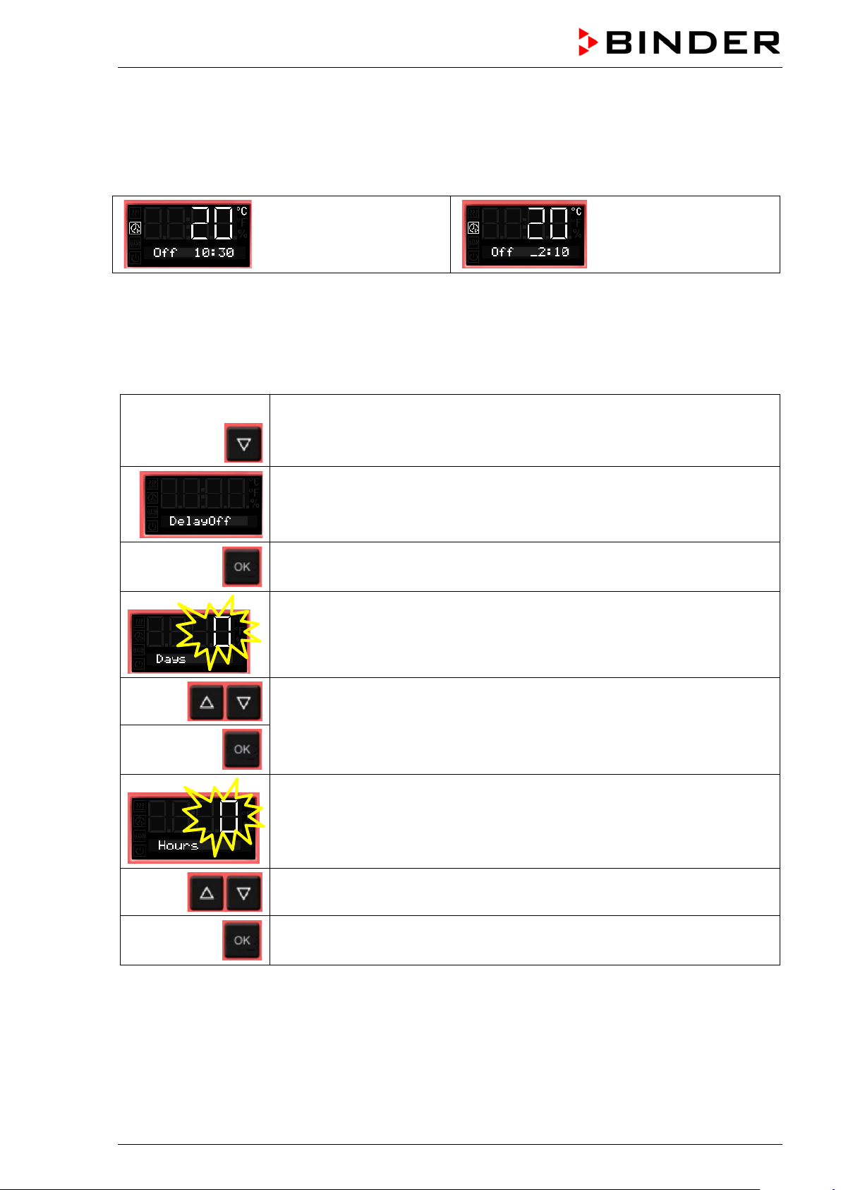
Timer run-time is set in days, hours, and minutes. If days have been entered, they are shown in the
controller display preceded b y an undersc ore:
Setting:
0 days (not shown),
10 hours, 30 minutes
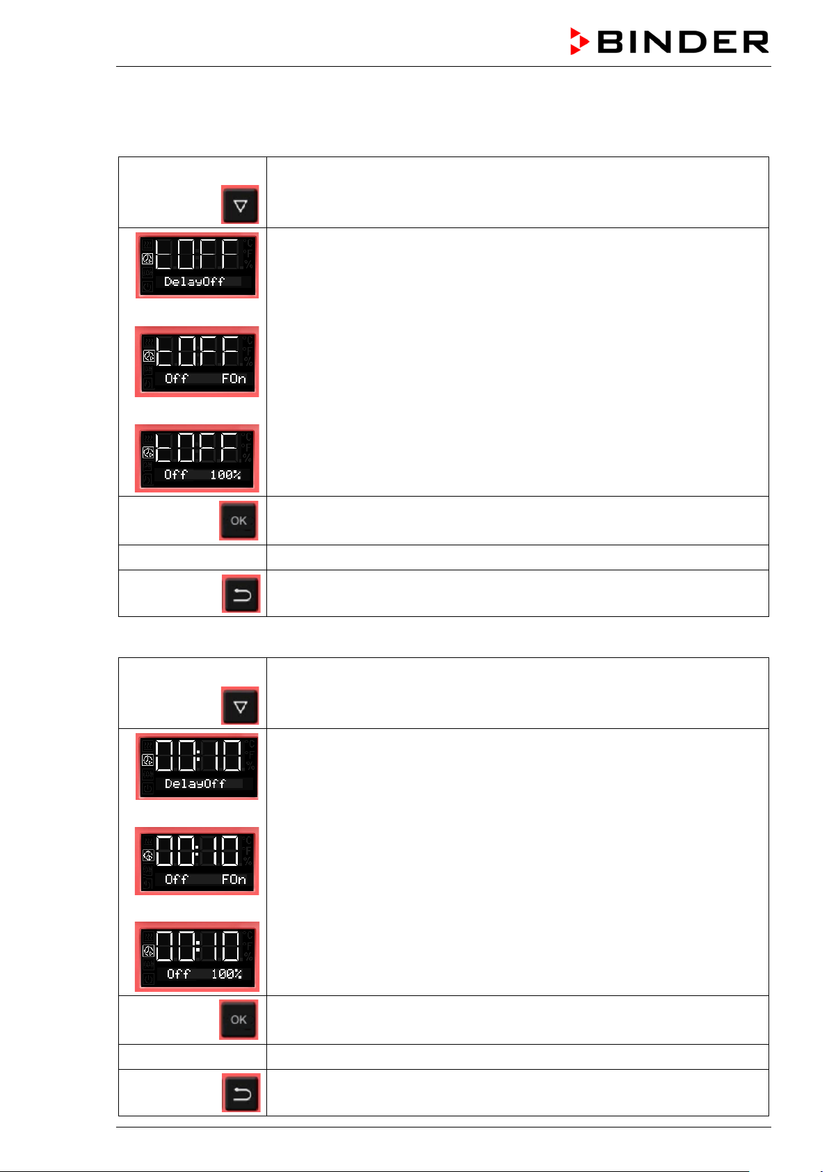
8.2 Timer function “Delayed Off”
8.2.1 Entry and activation of the timer run-time and fan setting
From Normal display
with the arrow-down button to the Timer function “Delayed Off” menu
(with connected USB device: press the arrow-down button twice)
Current Timer function “Delayed Off”
Confirm with OK and go on to enter the days of the timer run-time.
Setting:
2 days, 10 hours
(minutes not shown)
The current timer run-time (days) is shown. The day value flashes.
Enter the days of the timer run-time (0 up to 9)
confirm with OK
and go on to enter the hours of the timer run-time
The hour value flashes.
Enter the hours of the timer run-time (0 up to 23)
confirm with OK
and go on to enter the minutes of the timer run-time
BD / BF / ED / FD / FED (E3.1) 07/2017 page 34/99
Page 35

The minute value flashes.
Enter the minutes of the timer run-time (0 up to 59)
and confirm with OK.
Chambers without fan (BD, ED):
The timer function “Delayed Off ” is activated
Back to Normal display.
Chamber with fixed fan speed (FD):
Select whether the fan shall operate or not after the timer has expired
The current setting of the fan operation is shown
Select fan operation: On (100 %) or Off (0 %)
and confirm with OK.
The timer function “Delayed Off” is activated
Back to Normal display.
BD / BF / ED / FD / FED (E3.1) 07/2017 page 35/99
Page 36

Chambers with adjustable fan speed (BF, FED):
Enter the fan speed set-point valid for the time after the timer has expired.
The current fan speed set-point is shown
Enter the fan speed in steps of 10 %
0 % and 40 % up to 100 %
and confirm with OK.
The timer function “Delayed Off” is activated
Back to Normal display.
Normal display during timer operati o n with time r function „Delayed Off“
The timer run-time until turning off the heating is running down.
Normal display after the timer has expired:
Chambers without fan (BD, ED):
Timer function “Delayed Off”.
The timer has expired. The heating is off.
Chamber with fixed fan speed (FD):
Timer function “Delayed Off”.
The timer has expired. The heating is off.
The fan is operating (On) or not (Off), as selected
Chambers with adjustable fan speed (BF, FED):
Timer function “Delayed Off”.
The timer has expired. The heating is off.
The fan operates with the selected fan speed.
When the timer has expired, the heating is off. The chamber cools down to ambient temperature.
To restart the chamber you need to turn off the timer function (chap. 8.2.2)
8.2.2 Turning off the timer function or changing the settings
To turn off the timer function “Delayed Off” during the time when it is still running, set all time values
(days, hours, minutes) to zero in the according menu (terminating the timer function). As lon g as th e timer
is running, the timer function settings can be subsequently modified in this menu.
After the timer expir ed you c an turn of f the timer function by pressing the OK butt on. A lter nat iv ely you can
also set the time to zero in the according menu.
BD / BF / ED / FD / FED (E3.1) 07/2017 page 36/99
Page 37
or
or
or
or
Turning off the timer function when the timer has expired
In Normal display press the OK button.
Alternatively you can set the time to zero:
From Normal display
with the arrow-down button to the Timer function “Delayed Off” menu
(with connected USB device: press the arrow-down button twice)
Chambers without fan (BD, ED):
Timer function “Delayed Off ”, the timer has expired. The heating is off.
Chamber with fixed fan speed (FD):
Timer function “Delayed Off ”, the timer has expired. The heating is off.
The fan is operating (On) or not (Off), as selected
Chambers with adjustable fan speed (BF, FED):
Timer function “Delayed Off ”, the timer has expired. The heating is off.
The fan operates with the selected fan speed.
Confirm the timer function “Delayed Off” with OK
see chap. 8.2.1 Set all time values to zero
2x
Changing or terminating the timer function when the timer is running:
Back to Normal display.
From Normal display
with the arrow-down button to the Timer function “Delayed Off” menu
(with connected USB device: press the arrow-down button twice)
Chambers without fan (BD, ED):
Timer function „Delayed Off“, the timer is running.
Chamber with fixed fan speed (FD):
Timer function “Delayed Off”, the timer is running.
Chambers with adjustable fan speed (BF, FED):
Timer function “Delayed Off”, the timer is running.
Confirm the timer function “Delayed Off” with OK
see chap. 8.2.1 Modify the time values or set them to zero to terminate the timer function
2x
BD / BF / ED / FD / FED (E3.1) 07/2017 page 37/99
Back to Normal display.
Page 38

8.3 Timer function “Temperature dependent Delayed Off” (BF, FED)
8.3.1 Entry and activation of the timer run-time, fan setting and set-point entry
From Normal display
with the arrow-down button to the Timer function “Temperature dependent
3 x
Delayed Off” menu
(with connected USB device: press the arrow-down button 4 times)
Current Timer function “Temperature dependent Delayed Off”
Confirm with OK and go on to enter the days of the timer run-time.
The current timer run-time (days) is shown. The day value flashes.
Enter the days of the timer run-time (0 up to 9)
confirm with OK
and go on to enter the hours of the timer run-time
The hour value flashes.
Enter the hours of the timer run-time (0 up to 23)
confirm with OK
and go on to enter the minutes of the timer run-time
The minute value flashes.
Enter the minutes of the timer run-time (0 up to 59)
confirm with OK
and go on to enter the temperature set-point
BD / BF / ED / FD / FED (E3.1) 07/2017 page 38/99
Page 39

The temperature set-point flashes.
When the set-point is reached, the timer starts running down.
Enter the temperature set-point,
confirm with OK and go on to enter the fan speed set-point valid for the time
after the timer has expired
The current fan speed is shown
Enter the fan speed in steps of 10 %
0 % and 40 % up to 100 %
and confirm with OK.
The timer function “Temperature dependent Delayed Off” is activated
Back to Normal display.
Normal display during timer operati o n with timer function „Temperature dependent Delayed Off“
Normal display while the timer is running
If the entered set-point exceeds the current actual value, the chamber heats
up.
As soon as the set-point is reached or exceeded, the timer starts running down
Normal display during the timer run-time.
The timer run-time until turning off the heating (and possibly the fan) is running.
Normal display after the timer has expired:
Timer function “Temperature dependent Delayed Off”.
The timer has expired. The heating is off. The fan operates with the selected
fan speed.
When the timer has expired, the heating is off. The chamber cools down to ambient temperature.
To restart the chamber you need to turn off the timer function (chap. 8.3.2).
BD / BF / ED / FD / FED (E3.1) 07/2017 page 39/99
Page 40

8.3.2 Turning off the timer function or changing the settings
To turn off the timer function “ T em per ature dependent Delayed Off” during the tim e when it is s til l runn in g,
set all time values (da ys, hours, minutes) to zero in th e according menu (term inating the timer function).
As long as the timer is running, the timer function settings can be subsequently modified in this menu.
After the timer ex pired you can tur n of f the t im er f unc tion by pressing the OK butt on. A lter nat iv ely you can
also set the time to zero in the according menu.
Turning off the timer function when the timer has expired
In Normal display press the OK button.
Alternatively you can set the time to zero:
From Normal display
with the arrow-down button to the Timer function “Temperature dependent
3 x
Delayed Off” menu
(with connected USB device: press the arrow-down button 4 times)
Timer function “Temperature dependent Delayed Off”, the timer has expired
Confirm the timer function “Temperature dependent Delayed Off” with OK
see chap. 8.3.1 Set all time values to zero
Back to Normal display
Changing or terminating the timer function when the timer is running:
From Normal display
with the arrow-down button to the Timer function “Temperature dependent
3 x
see chap. 8.3.1
Delayed Off” menu
(with connected USB device: press the arrow-down button 4 times)
Timer function “Temperature dependent Delayed Off”, the timer is running
Confirm the timer function “Temperature dependent Delayed Off” with OK
Modify the time values or set all time values to zero to terminate the timer function
Back to Normal display
BD / BF / ED / FD / FED (E3.1) 07/2017 page 40/99
Page 41
8.4 Timer function “Delayed On” (BF, FED)
8.4.1 Entry and activation of the timer run-time and fan setting
From Normal display
2 x
with the arrow-down button to the Timer function “Delayed On” menu
(with connected USB device: press the arrow-down button 3 times)
Current timer function “Delayed On”
Confirm with OK and go on to enter the fan speed set-point valid during the
time the timer is running
The current fan speed set-point is shown
Enter the fan speed in steps of 10 %
0 % and 40 % up to 100 %
Confirm with OK and go on to enter the days of the timer run-time.
The current timer run-time (days) is shown. The day value flashes.
Enter the days of the timer run-time (0 up to 9)
confirm with OK
and go on to enter the hours of the timer run-time
The hour value flashes.
Enter the hours of the timer run-time (0 up to 23),
confirm with OK
and go on to enter the minutes of the timer run-time
BD / BF / ED / FD / FED (E3.1) 07/2017 page 41/99
Page 42
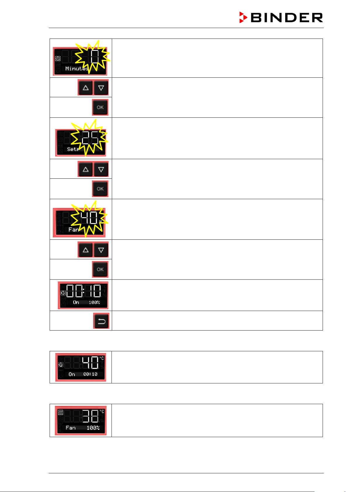
The minute value flashes.
Enter the minutes of the timer run-time (0 up to 59)
confirm with OK
and go on to enter the temperature set-point
The temperature set-point flashes.
Enter the temperature set-point,
confirm with OK and go on to enter the fan speed set-point valid for the time
after the timer has expired
The current fan speed set-point is shown
Enter the fan speed in steps of 10 % -
0 % and 40 % up to 100 %
and confirm with OK.
The timer function “Delayed On” is activated
2x
Normal display during timer operati o n with timer function “Delayed On”
Back to Normal display.
The Timer run-time until turning on the heating is running.
Timer function “Delayed On”.
The heating is off, temperature approximates ambient temperature.
Normal display after the timer has expired:
The timer has expired. The time function is off.
The heating is active to equilibrate the temperature set-point.
The fan operates with the selected fan speed.
BD / BF / ED / FD / FED (E3.1) 07/2017 page 42/99
Page 43

8.4.2 Changing the settings
After the timer expir ed, the timer function „Delayed On“ deactiv ates, therefore turning the func tion off is
not required.
As long as the timer is still running, the timer function settings can be subsequently modified in this menu.
To terminate the timer function, all time values (days, hours, minutes) must be set to zero in the according
menu.
Changing or terminating the timer function when the timer is running:
From Normal display during timer operation
2 x
see chap. 8.4.1
2x
with the arrow-down button to the Timer function “Delayed On” menu.
(with connected USB device: press the arrow-down button 3 times)
Timer function “Delayed On”, the timer is running.
The fan operates with the selected fan speed.
Confirm the timer function “Delayed On” with OK
Modify the time values or set all time values to zero to terminate the timer
function
Back to Normal display.
8.5 Temperature programming example (BF, FED)
The chamber shall hea t up to a tem perature of 50 °C, m aintain this tem perature f or three h ours and th en
turn off.
Proceeding: Select timer function “Temperature depe ndent Delayed Off“ (chap. 8.3) and perform the following settings:
• Enter a timer run-time of 3 hours
• Enter the set point 50 °C
• Specify the fan speed after the timer expires
BD / BF / ED / FD / FED (E3.1) 07/2017 page 43/99
Page 44

9. Ramp function
9.1 General information
You can program tem peratur e ramps in order to extend heating up t im es . T his may be nec ess ary in some
cases to prevent temperature stress in the material during the heating up phase. Temperature ramps
should only be used if required. Using them may result in considerably slowing down the heating up
times. When the ramp function is turned off, the chamber will heat up with its maximum heating capacity.
The entry means the nom inal value gradient and limits the max imum temperature increase t o this value.
Due to the heat and evapo ration energy assumed b y the drying material, smaller temperature gradients
may also result.
A ramp proceeds from a previously entered set-point to a new, higher one. The tem perature must be
equilibrated to the start set-point. Perform the setting in the following 3 steps:
1. Enter the temperature set-point as start ramp set-point and let the tem perature equilibrate to this
value
2. Define the temperature increase (ramp gradient) in °C/min or in °F/min in the setting menu “Ramp
function”
You can select a gradient from „0.0“ up to „1.0“ or from „1“ up to „10“ according to the chamber type.
When setting t he gradient to „0.0“ or „0“, r amp function is turned of f. The chamber will then heat up
with its maximum heating capacity.
The chamber will tr y to heat up accor ding to the ente red gradient, i.e. w ith a speed of xx degree per
minute. A heat ing-up rate of 0.4 °C/m in for the incubators BD and BF resp. 4 °C/min for the heating
and drying ovens ED, FD and FED can be regarded as a realistic maximum.
3. Enter the target ramp set-point in the “ramp function” setting menu.
As soon as the entries h av e bee n ad opt ed, t he r amp function is activated. The cham ber heats up with t he
entered gradient, if the set ramp target value lies above the actual temperature va lue.
During ramp operation the effective ramp set-point continua lly rises in acc ordanc e to the entered grad i-
ent from the previ ously ent ered set-point to the new o ne. The actual value foll ows this c ontinua lly chan ging eff ective ramp s et-point. As soon as the ramp target value is reached, this tem perature is maintained
constant.
The actual temperature value, the selected gradient, and the targ et va lue are shown in Normal display.
The effective ramp set-point can be seen through the temperature set-point function.
BD / BF / ED / FD / FED (E3.1) 07/2017 page 44/99
Page 45

9.2 Setting and displaying the ramp function
From Normal display
without fan 3x
with fan 4x
with the arrow-up button to the Ramp function menu.
Ramp function (not programmed)
Press OK to enter the gradient in degree per minute.
The gradient flashes.
Enter the gradient (0 up to 9)
confirm with OK and go on toenter the target ramp set-point
The target ramp set-point value flashes.
Enter the target ramp set-point
and confirm with OK.
Selected ramp with gradient 1 and target ramp set-point 40 °C (example)
Back to Normal display.
Normal display showing the actual temperature, the gradient and the target
ramp set-point (example: 40 °C)
Temperature course with ramp function
after 1
Normal display
minute
Normal display
after 2
minutes
Normal display
Etc.
BD / BF / ED / FD / FED (E3.1) 07/2017 page 45/99
Page 46
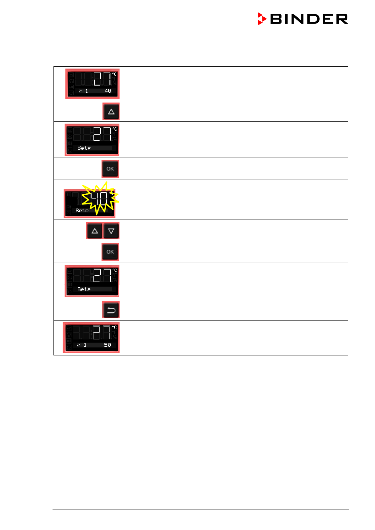
9.3 Displaying the effective ramp set-point and changing the target ramp set-
point
From Normal display showing the actual temperature (example: 27 °C), the
gradient (example: 1) and the target ramp set-point (example: 40 °C)
to the display of the effective ramp set-point
The effective ramp set-point is displayed
Press OK to set the target ramp set-point
The target ramp set-point value flashes.
Enter the target ramp set-point
and confirm with OK.
The effective ramp set-point is displayed
2x
Back to Normal display.
Normal display showing the actual temperature, the gradient and the modif ied
target ramp set-point (example: 50 °C)
BD / BF / ED / FD / FED (E3.1) 07/2017 page 46/99
Page 47
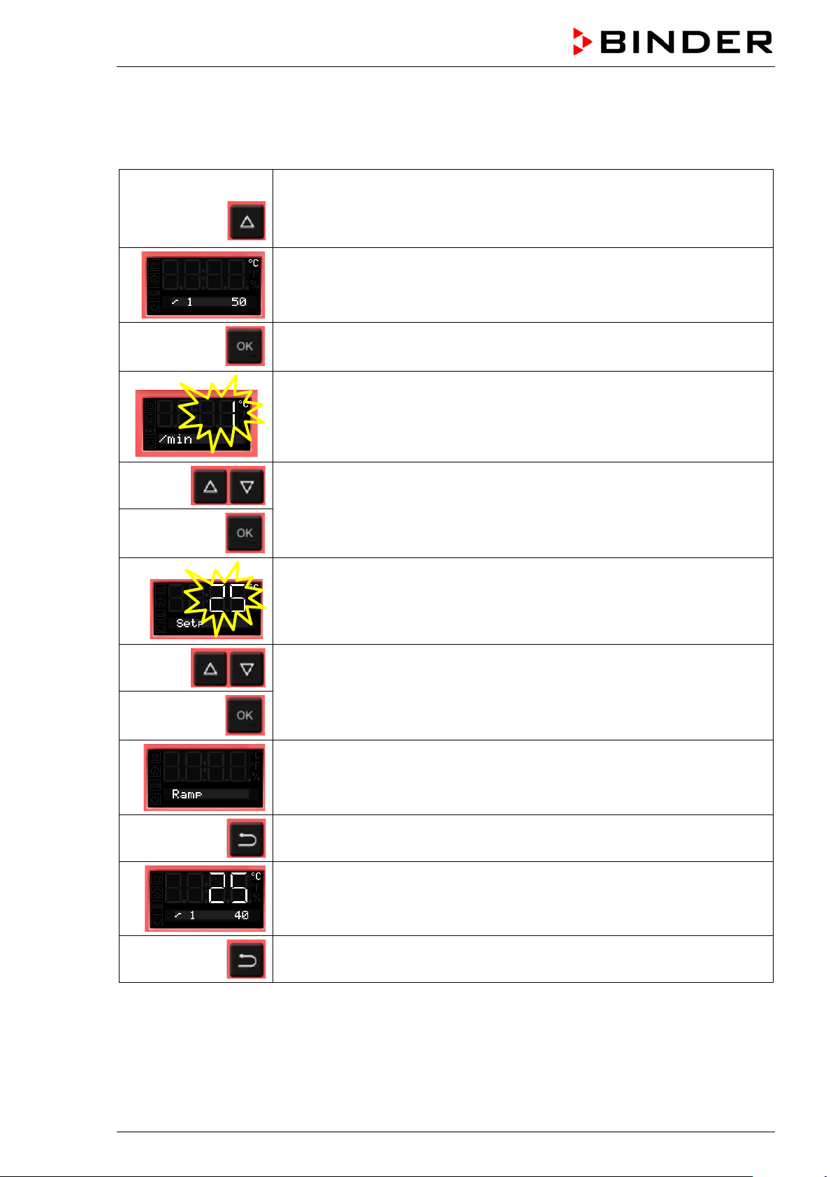
9.4 Turning off the ramp function
To turn off the ram p function, the gradient m ust be set to zero in the accor ding menu. T he set-point can
be entered as desired.
From Normal display
without fan 3x
with fan 4x
with the arrow-up button to the Ramp function menu
Ramp function with programmed gradient and target ramp set-point
Press OK to enter the gradient in degree per minute.
The gradient flashes.
Enter the gradient zero (turning off the ramp function)
confirm with OK and go on to the ramp target value
The target ramp set-point value flashes.
Enter the target ramp set-point
and confirm with OK.
Ramp function (not progra m med)
Back to Normal display.
Normal display showing the actual temperature, the gradient and the target
ramp set-point (example: 40 °C)
2x
Instead of turning off the ramp function (gradient = 0), you can also modify the settings of the gradient
and target ramp set-point in this menu.
Back to Normal display.
BD / BF / ED / FD / FED (E3.1) 07/2017 page 47/99
Page 48
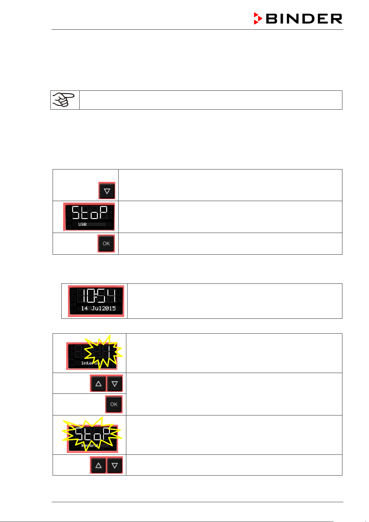
10. Data recording via USB interface
The USB interface located in the triangular instrument panel serves to read out the measured values,
which are put out in real tim e. Following data is recor ded: Timer, ac tual temperature value, temperature
set-point, Object tem perature sensor ( chambers with opti on Object temperatur e display), Fan (chambers
with fan), air flap position, safety controller, analog output (option), heating regulation ratio.
Connect only USB sticks to the USB interface.
Data are stored direct ly on the USB stick. They are is sued in the selected language as a sprea dsheet
with the file extension “.csv” and can be further processed in the desired program.
10.1 Starting data recording
Connect the USB stick to the interface located in the triangular instrument panel.
From Normal display
with the arrow-down button to the USB menu
Current state of data recording: stopped
Confirm with OK.
Chambers without the real time clock option do not save date and tim e after shut-down. To m ake
sure that recorded d ata is provided with the correct d ate and time, with these chambers it is req uired
to enter date and time first :
The current date is displayed.
For setting, proceed as described in chap. 6.4.
After entry of the minute and confirmation with OK, further setting in the USB menu continues.
The data recording interval flashes.
Enter the interval in minutes
and confirm with OK.
The current state of data recording (stopped) flashes.
Change to start data recording.
BD / BF / ED / FD / FED (E3.1) 07/2017 page 48/99
Page 49

The current state of data recording (started) flashes
Confirm with OK.
Data recording is running.
Back to Normal display.
Data recording continues also during stand-by mode of the chamber. Disconnecting the power supply
interrupts data recordin g, whic h cont inues af ter the po wer retur ns. To terminate data recordi ng, sto p it via
the menu (chap. 10.2).
10.2 Terminating data recording
From Normal display
with the arrow-down button to the USB menu
Current state of data recording: running
Confirm with OK.
The current state of data recording (running) flashes
Change to stop data recording
The current state of data recording (stopped) flashes
Confirm with OK.
Data recording is stopped.
Back to Normal display.
BD / BF / ED / FD / FED (E3.1) 07/2017 page 49/99
Page 50

11. Network configuration for chambers with Ethernet interface
The settings of this subm enu are used for networking chambers with an Etherne t interface, e.g. to connect them with BINDER’s communication software APT-COM™ 3 DataControlSystem (option, chap.
12.1).
This menu subsequently offers the following settings:
• Display of the chamber‘s MAC address (no setting)
• Switching on and off the DHCP state
• Entering the IP address
• Entering the subnet mask number
• Entering the gateway number
From Normal display
without fan 5x
with fan 6x
5 x
with the arrow-up button to the user menu
Confirm with OK.
Enter the password (factory setting: 00 00)
and confirm each entry with OK.
with the arrow-up button to the Ethernet menu.
Confirm with OK.
The first digits of the MAC address are shown.
Continue with OK. The middle digits of the MAC address are shown.
Continue with OK. The last digits of the M AC address are shown.
Displaying the chamber’s MAC address serves to identify the chamber in the Ethernet network.
Example: 00-0F-67-0F-42-40
00-0F 67-0F 42-40
BD / BF / ED / FD / FED (E3.1) 07/2017 page 50/99
Page 51
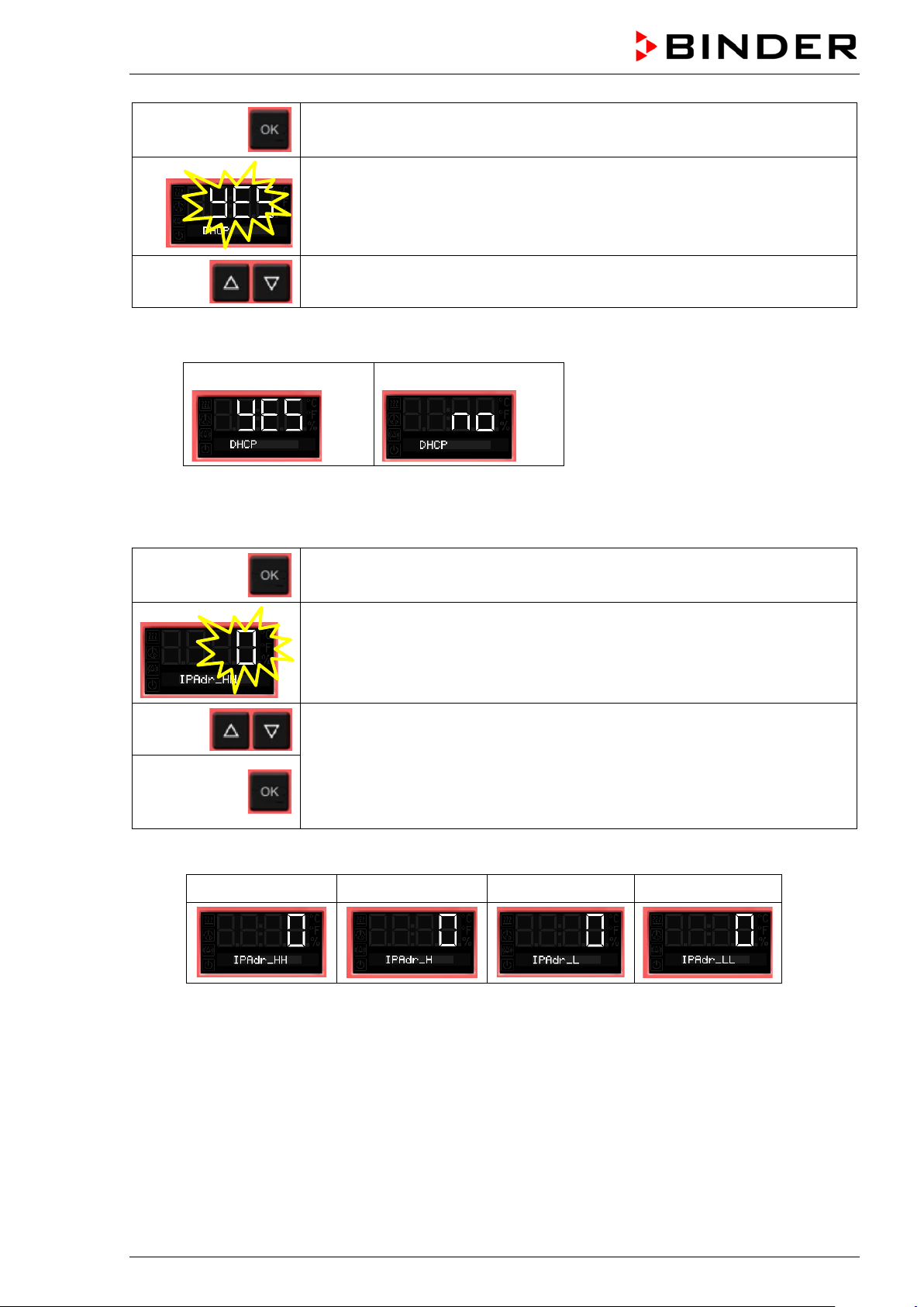
Continue with OK to switching on and off the DHCP state
The current DHCP state is dis p l a yed (on). The setting flashes.
Select the setting with the arrow buttons.
There are the following options:
DHCP switched on:
To configure the network settings, the DHCP state m ust be switched off. Otherwise, the DHCPserver would assign the network configuration..
Confirm with OK and go on to enter the IP address.
The first digits of the current IP address are shown.
The setting flashes.
Enter the desired values with the arro w buttons
and confirm with OK.
The next digits of the IP address are shown.
Enter the desired values according ly.
Example value: 0.0.0.0
DHCP switched off:
0 0 0 0
BD / BF / ED / FD / FED (E3.1) 07/2017 page 51/99
Page 52
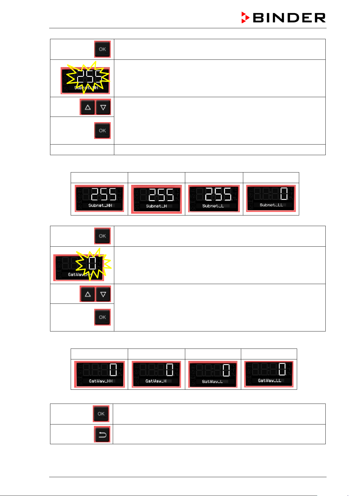
Confirm with OK and go on to enter the subnet mask.
The first digits of the current subnet mask are shown.
The setting flashes.
Enter the desired values wit h the arro w buttons
and confirm with OK.
The next digits of the subnet mask are shown.
Enter the desired values according ly.
Example value: 255.255.255.0
255 255 255 0
Confirm with OK and go on to enter the gateway.
The first digits of the current gateway are shown.
The setting flashes.
Enter the desired values with the arro w buttons
and confirm with OK.
The next digits of the gateway are shown.
Enter the desired values according ly.
Example value: 0.0.0.0
0 0 0 0
Confirm with OK.
2x
BD / BF / ED / FD / FED (E3.1) 07/2017 page 52/99
Back to Normal display.
Page 53
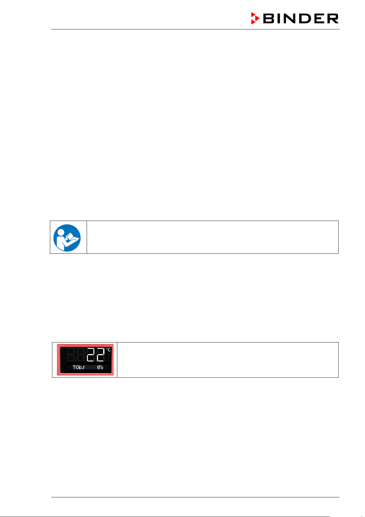
12. Options
12.1 Comm uni cation software APT-COM™ 3 DataControlSystem (option)
The chamber is regu larly (FED) or optionally equ ipped with an Ethernet inter face on the chamber rear
that can connect the BINDER communication software APT-COM™ 3 DataControlSystem. The actual
temperature value is gi ven at adjusta ble int ervals. Program m ing can be per form ed graph icall y via PC. U p
to 30 chambers can be cr oss-link ed. T he MAC Addres s is indicated in th e Ethernet menu (chap. 11). For
further informat ion, please refer to the operating m anual of the BINDER comm unication software APTCOM™ 3.
To establish a connection via the chamber’s Ethernet interface, the chamber must be turned off.
12.2 Da ta logger kits (option)
BINDER Data Logger Kits of fer an independent long-term meas uring system for temperature. They are
equipped with a keyboard and a large LCD display, alarm functions and a real-time f unction. Measurement data are recor ded in the Data Logger a nd can be read out after the measurement via the RS232
interface of the Data Log ge r. It offers a programmable measuring interval and per mits storing up to 64000
measuring values. Reading out is done with the Data Logger evaluation software. You can give out a
combined alarm and status protocol directly to a serial printer.
For BD/BF: Data Logger Kit T 220: Temperature range -90 °C / -130 °F up to +220 °C / 428 °F
For ED/FD/FED: Data Logger Kit T 350: Temperature range 0 °C / 32 °F up to +350 °C / 662 °F
For detailed information on installation and operation of the BINDER Data Logger, please
refer to the mounting instructions Art. No. 7001-0204 and to the original user manual of the
manufacturer, supplied with the data logger.
12.3 Object temperature display with additional Pt100 temperature sensor (op-
tion)
With this option an a dditional flexible temper ature sensor Pt100 measures the chamber temperature or
the temperature of t he ch arging material which is shown on t he co ntro ller. T he sens or-top protec tive t ube
of the flexible Pt100 can be immersed into liquid substances.
The object temperat ure display enables the det ermination of the actual temperature of the chargi ng material during the whole process. The object temperature is displayed in the controller in Normal Display.
Chamber with option object temperature display:
Actual temperature value and actual object temperature value
Technical data of thePt100 sensor:
• Three-wire technique
• Class B (DIN EN 60751)
• Temperature range up to 320 °C / 608 °F
• Stainless steel protective tube 45 mm length, material no. 1.4501
BD / BF / ED / FD / FED (E3.1) 07/2017 page 53/99
Page 54

A suitable DIN plug is enclosed.
CAUTION
12.4 Analog output for temperature (option)
With this option the chamber is equipped with an analog output 4-20 mA for temperature. This output
permits transmitting data to external data registration systems or devices.
The connection is carried out as a DIN socket at the rear of the chamber as follows:
ANALOG OUTPUT 4-20 mA DC
PIN 1: Temperature –
PIN 2: Temperature +
Temperature range:
BD, BF: 0 °C / 32 °F to +100 °C / 212 °F
Figure 8: Pin allocation of DIN socket for option analog outputs
ED, FD, FED: 0 °C / 32 °F to +300 °C / 572 °F
12.5 Water protected disconnectable internal socket (option BD, BF)
You can turn on or of f the disc onnectab le water protected i nternal soc ket (C A3GD) f or line voltage inside
the chamber by the s witch in the triangular ins trument panel, independen t of the incubator operati ng or
not. Thus, devices operate d inside the incu bator can be started or stopped witho ut any need to o pen the
chamber doors.
The internal socket provides a protective conductor, theref ore it is possible to connect appliances with
protection class I.
The internal socket is splash proof.
IP system of protection 67 230 V 1N ~ 50-60 Hz. Charge max. 500 W
Maximum permitted operating temperature with this option: 90 °C / 194 °F.
WARNING
Exceeding of the permitted maximum temperature.
Electrical hazard.
Danger of death.
Damage to the internal socket.
∅ Do NOT exceed the temperature set-point of 90 °C / 194 °F.
Set the safety controller class 3.1 to 90 °C / 194 °F.
Heat emission of electrical devices connected inside the chamber may modify the temperature
range.
Risk of short circuit.
Damage to the chamber.
Use the delivered plug only (IP protection type 66). Plug-in the plug and turn it to se-
cure.
If the socket is not used, close the lift-up lid and turn it for securing.
BD / BF / ED / FD / FED (E3.1) 07/2017 page 54/99
Page 55

Controller shutdown by the standby button has no effect on the internal socket.
WARNING
Internal socket switched on even though controller is shut down.
Electrical hazard.
Turn off the internal socket separately, when not in use, by the switch in the triangular
instrument panel
12.6 HEPA fresh air filter (optio n for FD, FED)
With this option, the introduced fresh air is cleaned by means of a high efficiency submicron particulate air
filter type HEPA class H 14 (acc. to DIN EN 1822:2 009). Repl ace the filter i nsert, if necessar y, by removing the metal cover of the filter at the left side of the chamber (Art. No. 6014-0003).
12.7 Mostly gas-tight version (option for BF, FD, FED)
With this option th e c hamber is additionally sealed, so the l os s whe n introd uc in g gas es is dec reas e d. The
chamber is not com pletely gas-tigh t, so it is im possibl e to establis h overpres sure. T he sealing d iminishes
the release of vapors via the housin g that may be set free from the charging material when heated. Carrying-off via the regular ev acuation duct, e.g. into a waste air insta llation, is likely to further reduce em issions.
The chamber is not completely gas-tight. Gases from inside the chamber can escape into the
surrounding atmospher e.
Observe the occupational exposure limit OEL for the released substance set by the national
authorities (formerly maximum permitted workplace concentration). Respect the relevant
regulations.
Any harmful gas that might escape has to be led out via good room ventilation or a suitable
exhaust system. Place the chamber, if necessary, below a gas vent.
The air flap does not cl ose the exhaust duct complete ly. The delivered p lug serves to avo id emerging of
vapors or loss of intro duced inert gas, if an y, via the exhaust duct. Due to special demands of heat resistance, use the delivered plug only.
CAUTION
Use of inappropriate plug.
Danger of inflammation.
To close the exhaust duct use the delivered plug only.
For drying purpose, pl ease remove the plug in order to permit dissipa tion of the generated vapor , which
would lead to condensation in the inner chamber.
12.8 Inert gas connection with mostly gas-tight version (option for BF, FD, FED)
With this option the chamber is additionally sealed, so the loss when introducing inert gases is decreased.
For details on the mostly gas-tight version please refer to chap. 8.4.
The chamber is equipped with two ports for inert gas ( nitrog en or nob le gases ).
The ports are located on the top panel in the middle and on the chamber re ar at the bottom right.
Each of these ports can be used as inlet or outlet, depending on the nature of the inert gas:
• lighter gas (nitrogen, helium): lower port as inlet
• heavy gas (e.g. argon): upper port as inlet
This distinction is important when operating with a reduced fan speed.
BD / BF / ED / FD / FED (E3.1) 07/2017 page 55/99
Page 56
Connection
Observe the legal requir ements and rele vant stand ard s and regu lations for the s af e handling of gas cylinders and inert gases.
General information for safe handling of gas cylinders:
• Store and use gas cylinders only in well ventilated areas.
• Open the gas cylinder valve slowly to avoid pressure surges
• Secure gas cylinders during storage and use against falling (chaining).
• Transport gas cylinders with a cylinder cart, do not carry, roll, or throw them
• Always close t he valve ev e n with app ar ent l y empty cylinders; sc r ew on the c ap when n ot in
use. Return gas cylinders with the valve closed
• Do not open gas cylinders by force. Mark them when damaged
• Observe relevant regulations for dealing with gas cylinders.
Connect a flexible gas t ube to the gas hos e connection a dapter (diameter 10mm), which is use d for gas
inlet, and secure it with hose clam ps (hose and h ose clamps ar e not enclosed). T here is a constan t gas
flow after establishing the connection.
After connecting the gas cylinder, check all gas connections for leaks (e.g. with leak spray or
diluted soap solution).
Use a pressure reducer an d make sure to avoid any exces sive outlet pressure when c onnecting the gas
hose to the chamber.
The chamber is not entirely gas-tight. Inert gases from inside the chamber can escape into the
surrounding atmospher e.
Inert gases in high c oncentrations is hazardous t o health. They are colorless and almost odorless and
therefore practicall y imperceptible. Inhalation of inert gases can cause drowsiness up to respirat ory arrest. When the O
gas that might escape has to be led out via good room ventilation or a suitable exhaust system.
content of the a ir d ec r eases be lo w 18% , t her e is r isk of death from lack of oxygen. An y
2
WARNING
High concentration of inert gas.
Risk of death by suffocation.
∅ Do NOT set up chambers in non-ventilated recesses.
Ensure technical ventilation measures.
Respect the relevant regulations for handling these gases.
Inert gases, which are heavier than air, may accumulate in low-lying areas of the installation
site.
The “Mostly gas-tight version” reduces the loss of gas.
Setting (sample values):
If you want to flush the cham ber with an air exchange rate of 1 per hour, set the flow rate on the
pressure reducer according to the interior volume.
Chamber with 56 l internal volume: The flow rate corresponding to 56 l / h is 0.9 l / min.
Chamber with 115 l internal volume: The flow rate corresponding to 115 l / h is 1.9 l / min.
Chamber with 260 l internal volume: The flow rate corresponding to 260 l / h is 4.3 l / min.
The air flap does not clos e the exhaust d uct complete ly. The deli vered plug serv es to avo id loss of introduced inert gas via the exh aust duct. Due to spec ial demands of heat resistance, use the d elivered plug
only.
BD / BF / ED / FD / FED (E3.1) 07/2017 page 56/99
Page 57

CAUTION
Use of inappropriate plug.
Danger of inflammation.
To close the exhaust duct use the delivered plug only.
For drying purpose, pl ease remove the plug in order to permit dissipa tion of the generated vapor , which
would lead to condensation in the inner chamber.
13. Maintenance, cleaning, and service
13.1 Maintenance intervals, service
DANGER
Electrical hazard.
Danger of death.
∅ The chamber must NOT become wet during operation or maintenance work.
∅ Do NOT remove the rear panel of the chamber.
Disconnect the chamber before conducting maintenance work. Disconnect the power
plug.
Ensure all maintenance work is conducted by licensed electricians or experts author-
ized by BINDER.
Ensure regular maintenance work is performed at least once a year.
The warranty becomes void if maintenance work is conducted by non-authorized pers onn el..
Replace the door gasket only when cold. Otherwise, the door gasket may become damaged.
We recommend taking out a maintenance agreement. Please consult BINDER Service.
BINDER telephone hotline: +49 (0) 7462 2005 555
BINDER fax hotline: +49 (0) 7462 2005 93555
BINDER e-mail hotline: service@binder-world.com
BINDER service hotline USA: +1 866 885 9794 or +1 631 224 4340 x3 (toll-free in the USA)
BINDER service hotline Asia Pacific: +852 390 705 04 or +852 390 705 03
BINDER service hotline Russia and CIS +7 495 988 15 16
BINDER Internet website http://www.binder-world.com
BINDER address BINDER GmbH, post office box 102, D-78502 Tuttlingen
International customers, please contact your local BINDER distributor.
BD / BF / ED / FD / FED (E3.1) 07/2017 page 57/99
Page 58

13.2 Cleaning and decontamination
Clean the chamber after each use to avoid potential corrosion damage by ingredients of the test material.
DANGER
Electrical hazard.
13.2.1 Cleaning
Disconnect the chamber from the power supply before cleaning. Disconnect the power plug.
The interior of the chamber must be kept clean. Thoroughly remove any residues of the charging material
Danger of death.
∅ Do NOT spill water or cleaning agents over the inner and outer surfaces.
Disconnect the chamber before cleaning. Disconnect the power plug.
Completely dry the chamber before turning it on again.
Wipe the surfaces with a moistened towel. In addition, you can use the following cleaning agents:
Exterior surfaces
inner chamber
racks
door gaskets
Instrument panel Standard commercial cleaning detergents free from acid or halides.
Zinc coated hinge parts
rear chamber wall
Do not use cleaning agent s that may cause a hazard due to reaction w ith components of the device or
the charging material. If there is doubt regarding the suitability of cleaning products, please contact
BINDER service.
We recommend using the neutral cleaning agent Art. No. 1002-0016 for a thorough cleaning.
Any corrosive damage that may arise following use of other cleaning agents is excluded from
liability by BIN DER GmbH.
Any corrosive damage caused by a lack of cleaning, is excluded from liability by BINDER
GmbH.
Standard commercial cleaning detergents free from acid or halides.
Alcohol-based solutions.
We recommend using the neutral cleaning agent Art. No. 1002-0016.
We recommend using the neutral cleaning agent Art. No. 1002-0016.
Standard commercial cleaning detergents free from acid or halides.
Do NOT use a neutral cleaning agent on zinc coated surfaces.
CAUTION
Danger of corrosion.
Damage to the chamber.
∅ Do NOT use acidic or chlorine cleaning detergents.
∅ Do NOT use a neutral cleaning agent on other kind of surfaces e.g., the zinc coated
hinge parts or the rear chamber wall.
For surface protection, perform cleaning as quickly as possible.
After cleaning completely remove cleaning agents from the surfaces with a moistened towel.
Let the chamber dry.
Soapsuds may contain chlorides and must therefore NOT be used for cleaning.
BD / BF / ED / FD / FED (E3.1) 07/2017 page 58/99
Page 59
With every decontamination method, always use adequate personal safety controls.
Following cleaning, leave the chamber door open or remove the access port plugs.
The neutral cleaning agent may cause health problems in contact with skin and if ingested.
Follow the operating instructions and safety hints labeled on the bottle of the neutral cleaning agent.
Recommended precautions: To protect the eyes use sealed protective goggles. Suitable protective
gloves with full contact: butyl or nitrile rubber, penetration time >480 minutes.
CAUTION
Contact with skin, ingestion.
Skin and eye damage due to chemical burns.
∅ Do not ingest. Keep away from food and beverages.
∅ Do NOT empty into drains.
Wear protective gloves and goggles.
Avoid skin contact.
13.2.2 Decontamination
The operator must ensure that proper decontamination is performed in case a contamination of the
chamber by hazardous substances has occurred.
Disconnect the chamber from the power supply prior to decontamination. Pull the power plug.
Do not use decontamination agents that may cause a hazard due to reaction with components of the
device or the charging material. If there is doubt regarding the suitability of cleaning products, please
contact BINDER service.
You can use the following disinfectants:
Inner chamber Standard commercial surface disinfectants free from acid or halides.
Alcohol-based solutions.
We recommend using the disinfectant spray Art. No. 1002-0022.
For chemical disinfection, we recommend using the disinfectant spray Art. No. 1002-0022.
Any corrosive damage that may arise following use of other disinfectants is excluded from
liability by BIN DER GmbH.
With every decontamination method, always use adequate personal safety controls.
BD / BF / ED / FD / FED (E3.1) 07/2017 page 59/99
Page 60

Gänsäcker 16, 78502 Tuttlingen, Germany
In case of impurit y of the interior with biolog ical or chem ical hazardous m aterial, ther e are three pos sible
procedures depending on the type of contamination and of the charging material.
1. The drying and heating ov ens ED , FD and F ED can be h ot air ster ili zed at 190 °C / 374 °F for at leas t
30 minutes. All inflammable goods must be r emoved from the interior before. W ith the incubators BD
and BF it is possible to perform a hot-air disinfection at 100 °C / 212 °F.
2. Spray the inner chamber with an appropriate disinfectant.
Before start-up, the chamber must be absolute dr y and vent ilate d, bec ause ex plo sive gas es m a y form
during the decontamination process.
3. BD, ED: If necessary, have strong ly contaminated inner chamber par ts removed by an engineer for
cleaning, or have t hem exchanged. Steri lize the inner cham ber parts in a sterilizer or autoc lave. You
can also remove and sterilize the racks.
In case of eye contact, the disinfectant spray may cause eye damage due to chemical
burns. Follow the operating instructions and safety hints labeled on the bottle of the disinfectant spray.
Recommended precautions: To protect the eyes use sealed protective goggles.
CAUTION
Eye contact.
Eye damage due to chemical burns.
∅ Do NOT empty into drains.
Wear protective goggles.
After using the disinfectant spray, allow the chamber to dry thoroughly, and aerate it sufficiently.
13.3 S ending the chamber back to BINDER GmbH
If you return a BINDER pro duct to us f or repair or an y other reason, we will onl y accept the produc t upon
presentation of an authorization number (RMA number) that has previously been issued to you. An
authorization num ber will be issued after r eceiving your com plaint either in writin g or by telephone prior
to your sending the BIND E R pr oduc t b ac k to us . T he auth ori zat ion n umber will be issued follo wing rec e ipt
of the information below:
• BINDER product type and serial number
• Date of purchase
• Name and address of the dealer from which you bought the BINDER product
• Exact description of the defect or fault
• Complete address, contact person and availability of that person
• Exact location of the BINDER product in your facility
• A contamination clearance certificate (chap. 19) must be faxed in advance
The authorization num ber m ust be applied to the p ac k agi ng in suc h a wa y that it c an be easily recognized
or be recorded clearly in the delivery documents.
For safety reasons we cannot accept a chamber delivery if it does not carry an authorization
number.
Return address:
BD / BF / ED / FD / FED (E3.1) 07/2017 page 60/99
BINDER GmbH, Abteilung Service
Page 61

Packing element
Material
Disposal
Straps to fix packing on pallet
Plastic
Plastic recycling
Non-wood (compressed matchwood, IPPC standard)
Metal
Metal recycling
Pallet (from size 115 on)
Solid wood (IPPC standard)
Wood recycling
Cardboard
Paper recycling
Metal
Metal recycling
Edge protection
Styropor® or PE foam
Plastic recycling
Protection of doors and racks
PE foam
Plastic recycling
Bag for operating manual
PE foil
Plastic recycling
Insulating air cushion foil (packing of
optional accessories)
The chambers bear the s ymbol for the mark ing of ele ctrical and electronic equipm ent m an-
14. Disposal
14.1 Disposal of the transport packing
Wooden transport box (option)
with metal screws
Transport box
with metal clamps
PE foil Plastic recycling
If recycling is not possible, all packing parts can also be disposed of with normal waste.
Wood recycling
14.2 Decommissioning
• Disconnect the chamber from the power supply (pull the power plug).
• With option inert gas connection (chap. 12.8): Close the inert gas supply and remove the gas
connection.
WARNING
High concentration of inert gas.
Risk of death by suffocation.
Respect the relevant regulations for handling these gases.
When decommissioning the chamber, turn off the inert gas supply.
• Temporal decommissioning: See indications for appropriate storage, chap. 3.3.
• Final decommissioning: Dispose of the chamber as described in chap. 14.3 to 14.5.
14.3 Disposal of the chamber in the Federal Republic of Germany
According to Annex I of Direc tive 2012/19/EU of the European Parliam ent and of the Council on waste
electrical and electronic equipment (WEEE), BINDER devices ar e classified as “monitoring and control
instruments” (categor y 9) onl y intended for pr ofession al use“. The y must not be disposed of at public collecting points.
ufactured / placed on the m ar ket in the EC after 13 Au gus t 2 005 an d b e dis pos e d of in s eparate collection according to Directive 2012/19/EU on waste electrical and electronic
equipment (WEEE) and German national law for electrical and electronic equipment (Elektro- und Elektronikgerätegesetz, Elek tr oG ). WEEE marking: crossed-out whee l ed bi n with
solid bar under. A significa nt part of the materials m ust be recycled in order to protect the
environment.
At the end of the device’s service lif e, have the device disposed of according to the Germ an national law
for electrical and electronic equipment (Elektro- und Elektronikgerätegesetz, ElektroG from 20 October
2015, BGBl. I p. 1739) or contact BINDER service who will organize taking back and disposal of the
chamber according to the Germ an national law for electrical and electronic equ ipment (Elektro- und Elektronikgerätegeset z, Elek tr oG from 20 October 2015, BGBl. I p. 1739).
BD / BF / ED / FD / FED (E3.1) 07/2017 page 61/99
Page 62
The chambers bear the s ymbol for the mark ing of electr ical and elec tronic e quipm ent ma n-
CAUTION
Violation against existing law.
∅ Do NOT dispose of BINDER devices at public collecting points.
Have the device disposed of professionally at a recycling company which is certified
according to the German national law for electrical and electronic equipment (Elektro-
und Elektronikgerätegesetz, ElektroG from 20 October 2015, BGBl. I p. 1739).
or
Instruct BINDER Service to dispose of the device. The general terms of payment and
delivery of BINDER GmbH apply, which were valid at the time of purchasing the cham-
ber.
Certified companies dis assemble waste BIND ER equipment in primar y substances for recycling ac cording to Directive 2012 /19/EU. In order to elim inate any health hazards to the employees of the rec ycling
companies, the devices must be free from toxic, infectious or radioactive substances.
Prior to handing the chamber over to a recycling company, it is the user’s responsibility that it
is free from toxic, infectious or radioactive substances.
• Prior to disposal, clean all introduced or residual toxic substances from the chamber.
• Prior to disposal, disinfect the chamber from all sources of infection. Be aware o f the fact
that sources of infection may also be located outside the inner chamber.
• If you cannot safely remove all t oxic substances and sour ces of infection from the cham-
ber, dispose of it as “special” waste according to national law.
• Fill out the contamination clearance certificate (chap. 19) and enclose it with the chamber.
WARNING
Contamination of the device with toxic, infectious or radioactive substances.
Danger of intoxication.
Danger of infection.
∅ NEVER take a chamber contaminated with toxic substances or sources of infection for
recycling according to Directive 2012/19/EU.
Prior to disposal, remove all toxic substances and sources of infection from the cham-
ber.
Dispose of a chamber from which all toxic substances or sources of infection cannot be
safely removed as special waste according to national law.
14.4 Dis posa l of the chamber in the member states of the EU except for the Federal Republic of Germany
According to Annex I of Direc tive 2012/19/EU of the European Parliam ent and of the Council on waste
electrical and electronic equipment (WEEE), BINDER devices ar e classified as “monitoring and control
instruments” (categor y 9) onl y intended for pr ofession al use“. The y must not be disposed of at public collecting points.
ufactured / placed on the mar ket in the EC after 13 Au gus t 2 005 an d b e d is pos e d of in separate collection according to the Directive 2012/19/EU on waste electrical and electronic
equipment (WEEE). WEEE marking: crossed-out wheeled bin with solid bar under.
At the end of the device’s service life, notify the distributor who sold you the device, who will
take back and dispose of the chamber according to the Directive 2012/19/EU on waste
electrical and electronic equipment (WEEE).
BD / BF / ED / FD / FED (E3.1) 07/2017 page 62/99
Page 63

CAUTION
Violation against existing law.
∅ Do NOT dispose of BINDER devices at public collecting points.
Have the device disposed of professionally at a recycling company which is certified
according to conversion of the Directive 2012/19/EU into national law.
or
Instruct the distributor who sold you the device to dispose of it. The agreements apply
that were reached with the distributor when purchasing the chamber (e.g. his general
terms of payment and delivery).
If your distributor is not able to take back and dispose of the chamber, please contact
BINDER service.
Certified companies dis assemble waste BIND ER equipment in primar y substances for recycling ac cording to Directive 2012/19/EU. In order to exclude any health hazard for the employees of the recycling
companies, the devices must be free from toxic, infectious or radioactive substances.
Prior to handing the chamber over to a recycling company, it is the user’s responsibility that it
is free from toxic, infectious or radioactive substances.
• Prior to disposal, clean all introduced or residual toxic substances from the chamber.
• Prior to disposal, disinfect the chamber from all sources of infection. Be aware o f the fact
that sources of infection may also be located outside the inner chamber.
• If you cannot safely remove all sour ces of infection and tox ic substances from the cham-
ber, dispose of it as “special” waste according to national law.
• Fill out the contamination clearance certificate (chap. 19) and enclose it with the chamber.
WARNING
Contamination of the device with toxic, infectious or radioactive substa nce s.
Danger of intoxication.
Danger of infection.
∅ NEVER take a chamber contaminated with toxic substances or sources of infection for
recycling according to Directive 2012/19/EU.
Prior to disposal, remove all toxic substances and sources of infection from the cham-
ber.
Dispose of a chamber from which all toxic substances or sources of infection cannot be
safely removed as “special” waste according to national law.
14.5 Disposal of the chamber in non-member states of the EU
CAUTION
Alteration of the environment.
For final decommissioning and disposal of the chamber, please contact BINDER Ser-
vice.
Follow the statutory regulations for appropriate, environmentally friendly disposal.
BD / BF / ED / FD / FED (E3.1) 07/2017 page 63/99
Page 64

Fault description
Possible cause
Required measures
Temperature
closed.
Door gasket defective.
Replace door gasket,
Controller not adjusted.
Calibrate and adjust controller.
Check the power supply for correct
voltage (chap. 4.2).
BF, FED: Fan speed set too
low
Fan defective.
Contact BINDER service.
Controller defective.
Pt 100 sensor defective.
Semiconductor relay defective
Controller not adjusted.
Calibrate and adjust controller.
Semiconductor relay defective.
Timer run off.
Re-program the timer or turn it off.
Semiconductor relay defective.
Controller defective.
Chamber without function, the
standby icon is displayed.
Press down the standby button until
the display lights up.
Check the settings of the temperavice class 3.1 (chap. 7.3).
Let cool down the chamber. Check
suitable limit value.
Safety device class 2 defective.
No power supply.
Check connection to power supply.
Disconnect the chamber from the
service
Controller defective.
Contact BINDER service.
Deviations from the indicated
heating-up times.
Load the chamber less or consider
longer heating-up times.
Controller
Message „1999” in the controller
display
Sensor rupture between sensor and controller.
15. Troubleshooting
Set-point temperature is not
reached after specified time.
BF, FD, FED: The fan doesn’t
turn or turns too slowly.
Chamber heating permanently,
set-point not held.
Chamber doesn’t heat up. Heating icon is displayed.
Chamber doesn’t heat up. No
heating icon in the display. Controller display working.
BD, BF: Alarm message “!TProt”
is displayed
Chamber door not properly
Wrong voltage.
Heating element defective.
Chamber in standby mode.
Safety device class 3.1 has
responded.
Completely close chamber door.
BF, FED: Set fan speed to 100%
Contact BINDER service.
Contact BINDER service.
Contact BINDER service.
ture set-point and of the safety de-
ED, FD, FED: Chamber without
function. Alarm message “!TLim”
is displayed
Chamber without any function.
Only qualified service personnel authorized by BINDER must perform repair.
Repaired chambers must comply with the BINDER quality standards.
Safety device class 2 has
turned off the chamber.
Overtemperature protective
device class 1 has turned off
the chamber.
Chamber fully loaded.
the settings of the temperature setpoint and of the safety device class
2 (chap. 7.3). If appropriate, select
Contact BINDER service.
power supply for at least 10 seconds
and let it cool down. If the device
responds again, contact BINDER
Contact BINDER service.
BD / BF / ED / FD / FED (E3.1) 07/2017 page 64/99
Page 65
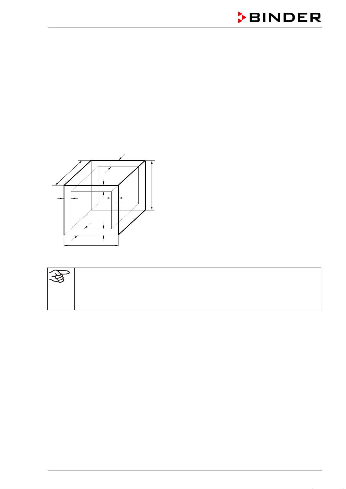
c
c
b
a
C
B
A
b
a
Figure 9: Determination of the useable volume
16. Technical description
16.1 Factory calibration and adjustment
This chamber was calibrated and adjusted in the factory. Calibration and adjustment were performed
using standardized tes t instructions, acc ording to the QM DIN EN ISO 9001 syst em applied by BINDER
(certified since December 1996 by TÜV CERT). All test equipm ent used i s subj ec t to th e administration of
measurement and test equi pment that is also cons tituent part of the BINDER QM DIN EN ISO 9001 systems. They are controlled and calibrated to a DKD-Standard at regular intervals.
16.2 De fi ni ti on of us able volume
The usable volume illustrated below is calculated as follows:
A, B, C = Internal dimensions (W, H, D)
a, b, c = Wall clearances
a = 0.1 x A
b = 0.1x B
c = 0.1 x C
= (A - 2a) x (B - 2b) x (C - 2c)
V
USE
The technical data refers to the defined usable volume.
Do NOT place samples outside this usable volume.
Do NOT load this volume by more than half to enable sufficient airflow inside the chamber.
Do NOT divide the usable volume into separate parts with large area samples.
Do NOT place samples too close to each other in order to permit circulation between them
and thus obtain a homogenous distribution of temperature.
16.3 O ver current protection
Single-phase devices are protected by one (U L chambers) or two miniature fuses agai nst over current,
accessible from the outside. The m iniature fuses are locat ed at the rear of th e chamber below th e strain
relief of the power c ord. Each fuse holder is equ ip ped w ith a fuse clip 5mm x 20 mm (c UL-Version 6,3x32
mm). A fuse may be replaced onl y with a substi tute of the sam e ratings. Refer t o the technic al data of the
respective device type.
Two-phase devices are equipped with a resettable miniature circuit breaker (combination element).
BD / BF / ED / FD / FED (E3.1) 07/2017 page 65/99
Page 66

Chamber size
BD 56
BD 115
BD 260
Exterior dimensions
Width, net
mm / inch
560 / 22.01
710 / 27.95
815 / 32.09
Height, gross (incl. feet)
mm / inch
625 / 24.60
735 / 28.94
965 / 37.99
Depth, net
mm / inch
565 / 22.24
605 / 23.82
760 / 29.92
duct)
Wall clearance rear (minimum)
mm / inch
160 / 6.30
160 / 6.30
160 / 6.30
Wall clearance side (minimum)
mm / inch
100 / 3.94
100 / 3.94
100 / 3.94
Exhaust duct, outer diameter
mm / inch
52 / 2.05
52 / 2.05
52 / 2.05
Doors
Number of doors
1 1
1
Number of inner glass doors
1 1
1
Interior dimensions
Width
mm / inch
360 / 14.17
510 / 20.08
610 / 24.02
Height
mm / inch
420 / 16.54
530 / 20.87
760 / 29.92
Depth
mm / inch
380 / 14.96
420 / 16.53
550 / 21.65
Interior volume
l / cu.ft.
57 / 2.01
112 / 3.96
255 / 9.01
Steam space volume
l / cu.ft.
63 / 2.22
127 / 4.49
279 / 9.85
Racks
Quantity of racks (regular)
2 2
2
Quantity of racks (max.)
4 5
8
Max. load per rack (standard rack)
Kg / lbs
30 / 66
30 / 66
44 / 88
Max. load per rack (optional perforated
shelf)
Max. load per rack (optional heavy load
rack)
Permitted total load
Kg / lbs
70 / 154
150 / 330
270 / 595
Weight
Weight (empty)
Kg / lbs
38 / 84
54 / 119
85 / 187
Temperature data
from … degrees
above ambient
up to
°C / °F
100 / 212
100 / 212
100 / 212
Temperature fluctuation at 37 °C / 98.6 °F
± K
0.2
0.1
0.2
Temperature uniformity (variation)
at 37 °C / 98.6 °F
Heating up time to 37 °C / 98.6 °F
minutes
45
55
65
Recovery time after door was opened for
30 sec at 37 °C / 98.6 °F
Electrical data
(model versions BD056-230V, BD115-230V, BD260-230V
IP system of protection acc. to EN 60529
IP
20
20
20
at 50 Hz power frequency
V
230
230
230
at 60 Hz power frequency
V
230
230
230
Current type
1N~
1N~
1N~
Nominal power
kW
0,30
0,35
0,85
Power plug of the power cable
shock proof plug
Chamber fuse
5x20 mm / 250V / time-lag (T)
Overtemperature protective device class 1
°C
120
120
120
16.4 BD technical data
Depth, gross (incl. door handle, exhaust
mm / inch 640 / 25.20 680 / 26.77 815 / 32.09
Kg / lbs 35 / 77 35 / 77 35 / 77
Kg / lbs 50 / 110 70 / 154 80 / 176
Temperature range
Nominal voltage
(+/-10%)
BD / BF / ED / FD / FED (E3.1) 07/2017 page 66/99
°C / °F 5 / 9 5 / 9 5 / 9
± K 0,4 0,4 0,4
minutes 16 16 19
A 6,3 external 6,3 external 8,0 external
Page 67

Chamber size
BD 56
BD 115
BD 260
Electrical data (continued)
Installation category acc. to IEC 61010-1
II
II
II
Pollution degree acc. to IEC 61010-1
2 2
2
Different electrical data for BD-UL constructed for the USA and Canada
(model versions BD056UL-120V, BD115UL-120V, BD 260UL-120V)
at 50 Hz power frequency
V
115
115
115
at 60 Hz power frequency
V
115
115
115
Nominal power
kW
0,30
0,35
0,95
Power plug of the power cable
NEMA
5-15P
5-15P
5-15P
Chamber fuse
5x20 mm / 250V / time-lag (T)
Environment-specific data
Energy consumption at 37 °C / 98.6 °F
Wh/h
25
25
40
Chamber size
BF 56
BF 115
BF 260
Exterior dimensions
Width, net
mm / inch
560 / 22.01
710 / 27.95
815 / 32.09
Height, gross (incl. feet)
mm / inch
625 / 24.60
735 / 28.94
965 / 37.99
Depth, net
mm / inch
565 / 22.24
605 / 23.82
760 / 29.92
Depth, gross (incl. door handle and exhaust
duct)
Wall clearance rear (minimum)
mm / inch
160 / 6.30
160 / 6.30
160 / 6.30
Wall clearance side (minimum)
mm / inch
100 / 3.94
100 / 3.94
100 / 3.94
Exhaust duct, outer diameter
mm / inch
52 / 2.05
52 / 2.05
52 / 2.05
Doors
Number of doors
1 1
1
Number of inner glass doors
1 1
1
Interior dimensions
Width
mm / inch
400 / 15.75
550 / 21.65
650 / 25.59
Height
mm / inch
440 / 17.32
550 / 21.65
780 / 30.71
Depth
mm / inch
340 / 13.39
380 / 14.96
510 / 20.08
Interior volume
l / cu.ft.
59 / 2.08
114 / 4.03
257 / 9.08
Steam space volume
l / cu.ft.
66 / 2.33
127 / 4.49
279 / 9.85
Nominal voltage
(+/-10%)
A 12.5 external 12.5 external 12.5 external
All technical data is spec ifi ed for unlo aded c ham bers with s tandar d equ ipm ent at an am bient tem peratur e
of +22 °C +/- 3° C / 71.6 °F +/- 5.4 °F and a power suppl y voltage fluctu ation of +/ -10%. Technical data is
determined in accordance to BINDER Factory Standard Part 2:2015 and DIN 12880:2007.
All indications are av erage values, typical for chambers p roduced in series. W e reserve the right
to change technical specifications at any time.
If the chamber is fully loaded, the specified heating up times may vary according to the load.
With option interior socket: If electrical devices are connected and operating inside the chamber, the temperature range may be modified due to heat emission.
16.5 BF technical data
mm / inch 640 / 25.20 680 / 26.77 815 / 32.09
BD / BF / ED / FD / FED (E3.1) 07/2017 page 67/99
Page 68
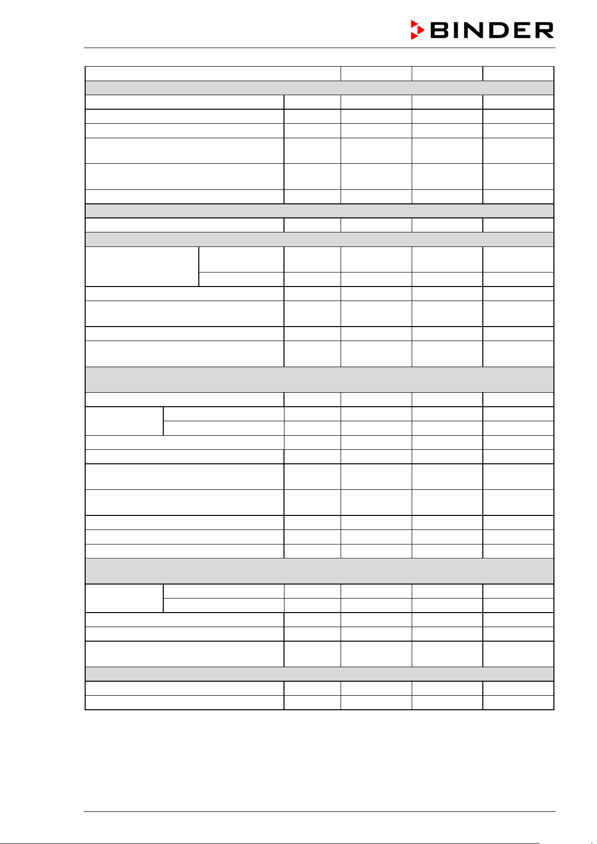
Chamber size
BF 56
BF 115
BF 260
Racks
Quantity of racks (regular)
2 2
2
Quantity of racks (max.)
4 5
8
Max. load per rack (standard rack)
Kg / lbs
30 / 66
30 / 66
44 / 88
Max. load per rack (optional perforated
shelf)
rack)
Permitted total load
Kg / lbs
70 / 154
150 / 330
270 / 595
Weight
Weight (empty)
Kg / lbs
39 / 86
54 / 119
85 / 187
Temperature data
from … degrees
above ambient
up to
°C / °F
100 / 212
100 / 212
100 / 212
Temperature fluctuation at 37 °C / 98.6 °F
± K
0.1
0.1
0.1
at 37 °C / 98.6 °F
Heating up time to 37 °C / 98.6 °F
minutes 8 8
8
30 sec at 37 °C / 98.6 °F
Electrical data
(model versions BF056-230V, BF115-230V, BF260-230V
IP system of protection acc. to EN 60529
IP
20
20
20
at 50 Hz power frequency
V
230
230
230
at 60 Hz power frequency
V
230
230
230
Current type
1N~
1N~
1N~
Nominal power
kW
0.40
0.40
0.90
shock proof
plug
shock proof
plug
shock proof
plug
Chamber fuse
5x20 mm / 250V / time-lag (T)
Overtemperature protective device class 1
°C
120
120
120
Installation category acc. to IEC 61010-1
II
II
II
Pollution degree acc. to IEC 61010-1
2 2
2
Different electrical data for BF-UL constructed for the USA and Canada
(model versions BF056UL-120V, BF115UL-120V, BF260UL-120V)
at 50 Hz power frequency
V
115
115
115
at 60 Hz power frequency
V
115
115
115
Power plug of the power cable
NEMA
5-15P
5-15P
5-15P
Nominal power
kW
0.40
0.40
1.00
Chamber fuse
5x20 mm / 250V / time-lag (T)
Environment-specific data
Noise level (mean value)
dB (A)
43
43
43
Energy consumption at 37 °C / 98.6 °F
Wh/h
60
60
70
Kg / lbs 35 / 77 35 / 77 35 / 77
Max. load per rack (optional heavy load
Temperature range
Temperature uniformity (variation)
Recovery time after door was opened for
Nominal voltage
(+/-10%)
Kg / lbs 50 / 110 70 / 154 80 / 176
°C / °F 7 / 12.6 8 / 14.4 7 / 12.6
± K 0.3 0.3 0.3
minutes 3 4 4
Power plug of the power cable
A 6.3 external 6.3 external 8.0 external
Nominal voltage
(+/-10%)
A 12.5 external 12.5 external 12.5 external
All technical data is spec ifi ed for unlo aded c ham bers with s tandar d equ ipm ent at an am bient tem peratur e
of +22 °C +/- 3° C / 71.6 °F +/- 5.4 °F and a power suppl y voltage fluctu ation of +/ -10%. Technical data is
determined in accordance to BINDER Factory Standard Part 2:2015 and DIN 12880:2007.
BD / BF / ED / FD / FED (E3.1) 07/2017 page 68/99
Page 69

Chamber size
ED 56
ED 115
ED 260
Exterior dimensions
Width, net
mm / inch
560 / 22.01
710 / 27.95
815 / 32.09
Height, gross (incl. feet)
mm / inch
625 / 24.60
735 / 28.94
965 / 37.99
Depth, net
mm / inch
565 / 22.24
605 / 23.82
760 / 29.92
Depth, gross (incl. door handle and exhaust
duct)
Wall clearance rear (minimum)
mm / inch
160 / 6.30
160 / 6.30
160 / 6.30
Wall clearance side (minimum)
mm / inch
100 / 3.94
100 / 3.94
100 / 3.94
Exhaust duct, outer diameter
mm / inch
52 / 2.05
52 / 2.05
52 / 2.05
Doors
Number of door(s)
1 1
1
Interior dimensions
Width
mm / inch
360 / 14.17
510 / 20.08
610 / 24.02
Height
mm / inch
420 / 16.54
530 / 20.87
760 / 29.92
Depth
mm / inch
380 / 14.96
425 / 16.73
550 / 21.65
Interior volume
l / cu.ft.
57 / 2.01
114 / 4.03
255 / 9.01
Steam space volume
l / cu.ft.
63
127 / 4.49
273 / 9.64
Racks
Quantity of racks (regular)
2 2
2
Quantity of racks (max.)
4 5
8
Max. load per rack (standard rack)
Kg / lbs
30 / 66
30 / 66
44 / 88
Max. load per rack (optional perforated
shelf)
Max. load per rack (optional heavy load
rack)
Permitted total load
Kg / lbs
70 / 154
150 / 330
270 / 595
Weight
Weight (empty)
Kg / lbs
39 / 86
54 / 119
85 / 187
Temperature data
above ambient
up to
°C / °F
300 / 572
300 / 572
300 / 572
Temperature fluctuation at 150 °C / 302 °F
± K
0.5
0.4
1.0
Temperature uniformity (variation)
at 150 °C / 302 °F
Heating up time to 150 °C / 302 °F
minutes
45
46
55
Recovery time after door was opened for 30
sec at 150 °C / 302 °F
All indications are av erage values, typical for chambers p roduced in series. W e reserve the right
to change technical specifications at any time.
If the chamber is fully loaded, the specified heating up times may vary according to the load.
With option interior socket: If electrical devices are connected and operating inside the chamber, the temperature range may be modified due to heat emission.
16.6 ED technical data
mm / inch 640 / 25.20 680 / 26.77 815 / 32.09
from … degrees
Temperature range
BD / BF / ED / FD / FED (E3.1) 07/2017 page 69/99
Kg / lbs 35 / 77 35 / 77 35 / 77
Kg / lbs 50 / 110 70 / 154 80 / 176
°C / °F 5 / 9 6 / 10.8 5 / 9
± K 2.5 2.0 2.0
minutes 35 16 20
Page 70

Chamber size
ED 56
ED 115
ED 260
Electrical data
(model versions ED056-230V, ED115-230V, ED260-230V
IP system of protection acc. to EN 60529
IP
20
20
20
at 50 Hz power frequency
V
230
230
230
at 60 Hz power frequency
V
230
230
230
Current type
1N~
1N~
1N~
Nominal power
kW
1.05
1.25
2.25
shock proof
plug
shock proof
plug
shock proof
plug
5x20 mm / 250V / time-lag (T)
Overtemperature protective device class 1
°C
330
330
330
Installation category acc. to IEC 61010-1
II
II
II
Pollution degree acc. to IEC 61010-1
2 2
2
Different electrical data for ED-UL constructed for the USA and Canada
(model versions ED056UL-120 V, ED115UL-120V, ED260UL -240V)
at 50 Hz power frequency
V
115
115
240
at 60 Hz power frequency
V
115
115
240
Current type
1N~
1N~
2~
Power plug of the power cable
NEMA
5-15P
5-15P
6-20P
Nominal power
kW
1.15
1.35
2.45
Chamber fuse
5x20 mm / 250V / time-lag (T)
ment)
Environment-specific data
Energy consumption at 150 °C / 302 °F
Wh/h
180
250
370
Chamber size
FD 56
FD 115
FD 260
Exterior dimensions
Width, net
mm / inch
560 / 22.01
710 / 27.95
815 / 32.09
Height, gross (incl. feet)
mm / inch
625 / 24.60
735 / 28.94
965 / 37.99
Depth, net
mm / inch
565 / 22.24
605 / 23.82
760 / 29.92
Depth, gross (incl. door handle and exhaust
duct)
Wall clearance rear (minimum)
mm / inch
160 / 6.30
160 / 6.30
160 / 6.30
Wall clearance side (minimum)
mm / inch
100 / 3.94
100 / 3.94
100 / 3.94
Exhaust duct, outer diameter
mm / inch
52 / 2.05
52 / 2.05
52 / 2.05
Nominal voltage
(+/-10%)
Power plug of the power cable
Chamber fuse
Nominal voltage
(+/-10%)
Miniature circuit breaker (combination ele-
All technical data is spec ifi ed for unlo aded c ham bers with s tandar d equ ipm ent at an am bient tem peratur e
of +22 °C +/- 3° C / 71.6 °F +/- 5.4 °F and a power suppl y voltage fluctu ation of +/ -10%. Technical data is
determined in accordance to BINDER Factory Standard Part 2:2015 and DIN 12880:2007.
A 6.3 external 6.3 external 12.5 external
A 12.5 external 12.5 external ---
A --- --- 16 extern
All indications are av erage values, typical for chambers p roduced in series. W e reserve the right
to change technical specifications at any time.
If the chamber is fully loaded, the specified heating up times may vary according to the load.
16.7 FD technical data
mm / inch 640 / 25.20 680 / 26.77 815 / 32.09
BD / BF / ED / FD / FED (E3.1) 07/2017 page 70/99
Page 71
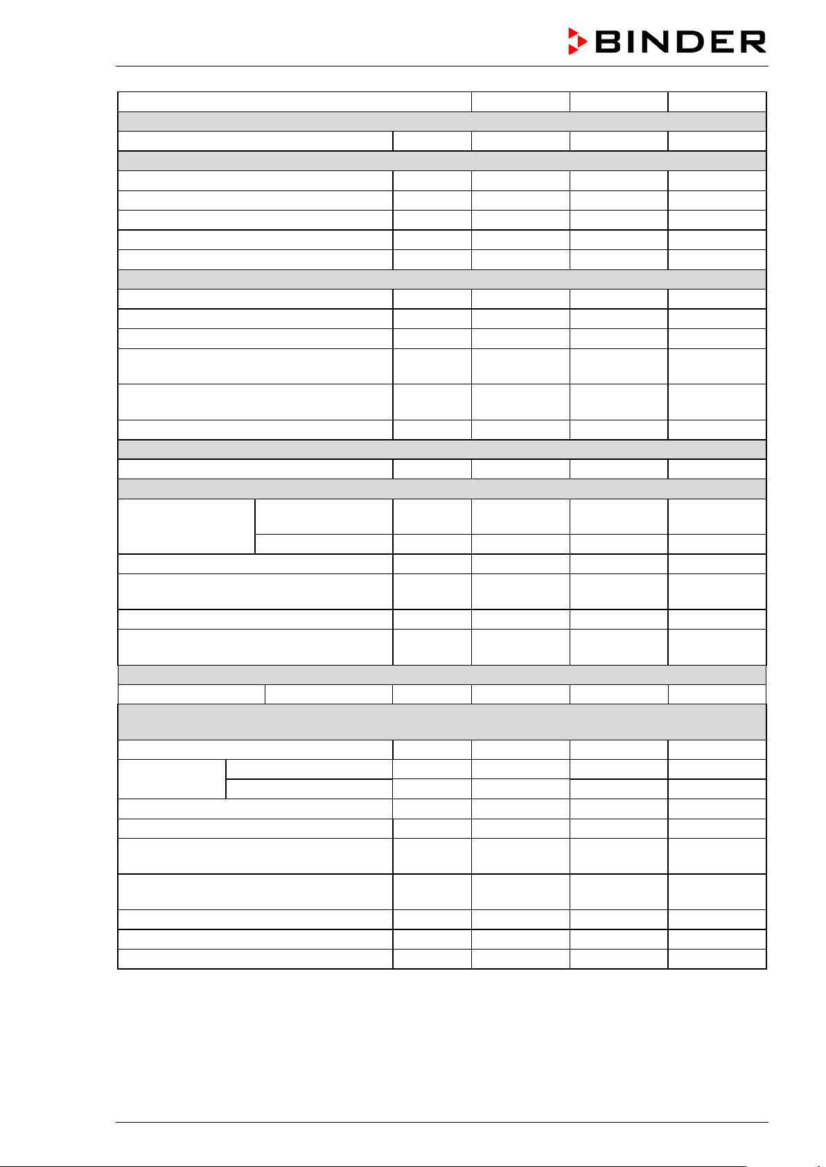
Chamber size
FD 56
FD 115
FD 260
Doors
Number of door(s)
1 1
1
Interior dimensions
Width
mm / inch
400 / 15.75
550 / 21.65
650 / 25.59
Height
mm / inch
440 / 17.32
550 / 21.65
780 / 30.71
Depth
mm / inch
345 / 13.58
385 / 15.16
510 / 20.08
Interior volume
l / cu.ft.
60 / 2.12
116 / 4.10
257 / 9.08
Steam space volume
l / cu.ft.
67 / 2.37
127 / 4.49
279 / 9.85
Racks
Quantity of racks (regular)
2 2
2
Quantity of racks (max.)
4 5
8
Max. load per rack (standard rack)
Kg / lbs
30 / 66
30 / 66
44 / 88
Max. load per rack (optional perforated
shelf)
rack)
Permitted total load
Kg / lbs
70 / 154
150 / 330
270 / 595
Weight
Weight (empty)
Kg / lbs
39 / 86
54 / 119
85 / 187
Temperature data
from … degrees
above ambient
up to
°C / °F
300 / 572
300 / 572
300 / 572
Temperature fluctuation at 150 °C / 302 °F
± K
0.3
0.3
0.5
at 150 °C / 302 °F
Heating up time to 150 °C / 302 °F
minutes
15
19
20
Recovery time after door was opened for 30
sec at 150 °C / 302 °F
Ventilation data
Air change
at 100 °C / 212 °F
x/h
80
32
9
Electrical data
(model versions FD056-230V, FD115-230V, FD260-230V
IP system of protection acc. to EN 60529
IP
20
20
20
at 50 Hz power frequency
V
230
230
230
at 60 Hz power frequency
V
230
230
230
Current type
1N~
1N~
1N~
Nominal power
kW
1.10
1.30
2.30
plug
plug
plug
Chamber fuse
5x20 mm / 250V / time-lag (T)
Overtemperature protective device class 1
°C
330
350
330
Installation category acc. to IEC 61010-1
II
II
II
Pollution degree acc. to IEC 61010-1
2 2
2
Kg / lbs 35 / 77 35 / 77 35 / 77
Max. load per rack (optional heavy load
Temperature range
Temperature uniformity (variation)
Nominal voltage
(+/-10%)
Kg / lbs 50 / 110 70 / 154 80 / 176
°C / °F 10 / 18 10 / 18 10 / 18
± K 1.7 1.7 1.9
minutes 4 5 6
Power plug of the power cable
BD / BF / ED / FD / FED (E3.1) 07/2017 page 71/99
shock proof
A 6.3 external 6.3 external 12.5 external
shock proof
shock proof
Page 72

Chamber size
FD 56
FD 115
FD 260
Different electrical data for FD-UL constructed for the USA and Canada
(model versions FD056UL-120V, FD115UL-120V, FD260UL-240V)
at 50 Hz power frequency
V
115
115
240
at 60 Hz power frequency
V
115
115
240
Current type
1N~
1N~
2~
Nominal power
kW
1.20
1.40
2.50
Power plug of the power cable
NEMA
5-15P
5-15P
6-20P
Chamber fuse 5x20 mm / 250V / time-lag (T)
A
12.5 external
12.5 external
---
Miniature circuit breaker (combination element)
Environment-specific data
Noise level (mean value)
dB (A)
43
43
43
Energy consumption at 150 °C / 302 °F
Wh/h
300
340
420
Chamber size
FED 56
FED 115
FED 260
Exterior dimensions
Width, net
mm / inch
560 / 22.01
710 / 27.95
815 / 32.09
Height, gross (incl. feet)
mm / inch
625 / 24.60
735 / 28.94
965 / 37.99
Depth, net
mm / inch
565 / 22.24
605 / 23.82
760 / 29.92
Depth, gross (incl. door handle and exhaust
duct)
Wall clearance rear (minimum)
mm / inch
160 / 6.30
160 / 6.30
160 / 6.30
Wall clearance side (minimum)
mm / inch
100 / 3.94
100 / 3.94
100 / 3.94
Exhaust duct, outer diameter
mm / inch
52 / 2.05
52 / 2.05
52 / 2.05
Doors
Number of door(s)
1 1
1
Interior dimensions
Width
mm / inch
400 / 15.75
550 / 21.65
650 / 25.59
Height
mm / inch
440 / 17.32
550 / 21.65
780 / 30.71
Depth
mm / inch
345 / 13.58
385 / 15.16
510 / 20.08
Interior volume
l / cu.ft.
60 / 2.12
116 / 4.10
257 / 9.08
Steam space volume
l / cu.ft.
67 / 2.37
127 / 4.49
279 / 9.85
Racks
Quantity of racks (regular)
2 2
2
Quantity of racks (max.)
4 5
8
Max. load per rack (standard rack)
Kg / lbs
30 / 66
30 / 66
44 / 88
Max. load per rack (optional perforated
shelf)
Max. load per rack (optional heavy load
rack)
Permitted total load
Kg / lbs
70 / 154
150 / 330
270 / 595
Nominal voltage
(+/-10%)
A --- --- 16 external
All technical data is spec ifi ed for unlo aded c ham bers with s tandar d equ ipm ent at an am bient tem peratur e
of +22 °C +/- 3° C / 71.6 °F +/- 5.4 °F and a power suppl y voltage fluctu ation of +/ -10%. Technical data is
determined in accordance to BINDER Factory Standard Part 2:2015 and DIN 12880:2007.
All indications are av erage values, typical for chambers p roduced in series. W e reserve the right
to change technical specifications at any time.
If the chamber is fully loaded, the specified heating up times may vary according to the load.
16.8 FED technical data
mm / inch 640 / 25.20 680 / 26.77 815 / 32.09
Kg / lbs 35 / 77 35 / 77 35 / 77
Kg / lbs 50 / 110 70 / 154 80 / 176
BD / BF / ED / FD / FED (E3.1) 07/2017 page 72/99
Page 73

Chamber size
FED 56
FED 115
FED 260
Weight
Weight (empty)
Kg / lbs
39 / 86
54 / 119
85 / 187
Temperature data
above ambient
up to
°C / °F
300 / 572
300 / 572
300 / 572
Temperature fluctuation at 150 °C / 302 °F
± K
0.3
0.3
0.5
Temperature uniformity (variation)
Heating up time to 150 °C / 302 °F
minutes
15
19
20
Recovery time after door was opened for 30
sec at 150 °C / 302 °F
Ventilation data
Air change
at 100 °C / 212 °F
x/h
80
32
9
Electrical data
(model versions FED056-230V, FED115-230V, FED260-230V
IP system of protection acc. to EN 60529
IP
20
20
20
at 50 Hz power frequency
V
230
230
230
at 60 Hz power frequency
V
230
230
230
Current type
1N~
1N~
1N~
Nominal power
kW
1.10
1.30
2.30
shock proof
plug
shock proof
plug
shock proof
plug
5x20 mm / 250V / time-lag (T)
external
external
external
Electrical data (continued)
(model versions FED056-230V, FED115-230V, FED260-230V
Overtemperature protective device class 1
°C
330
350
330
Installation category acc. to IEC 61010-1
II
II
II
Pollution degree acc. to IEC 61010-1
2 2
2
Different electrical data for FED-UL constructed for the USA and Canada
(model versions FED056UL-120V, FED115UL-120V, FED260UL-240V)
at 50 Hz power frequency
V
115
115
240
at 60 Hz power frequency
V
115
115
240
Current type
1N~
1N~
2~
Nominal power
kW
1.20
1.40
2.50
Power plug of the power cable
NEMA
5-15P
5-15P
6-20P
Chamber fuse
5x20 mm / 250V / time-lag (T)
ment)
Environment-specific data
Noise level (mean value)
dB (A)
43
43
43
Energy consumption at 150 °C / 302 °F
Wh/h
300
340
420
from … degrees
Temperature range
at 150 °C / 302 °F
Nominal voltage
(+/-10%)
Power plug of the power cable
Chamber fuse
°C / °F 10 / 18 10 / 18 10 / 18
± K 1.4 1.2 1.6
minutes 4 5 6
A
6.3
6.3
12.5
Nominal voltage
(+/-10%)
A 12.5 external 12.5 external ---
Miniature circuit breaker (combination ele-
All technical data is spec ifi ed for unlo aded chambers with sta ndard equ ipm ent at an am bient tem per ature
of +22 °C +/- 3° C / 71.6 °F +/- 5.4 °F and a power suppl y voltage fluctu ation of +/-10%. T echnical data is
determined in accordance to BINDER Factory Standard Part 2:2015 and DIN 12880:2007.
All indications are av erage values, typical for chambers p roduced in series. W e reserve the right
to change technical specifications at any time.
If the chamber is fully loaded, the specified heating up times may vary according to the load.
A --- --- 16 external
BD / BF / ED / FD / FED (E3.1) 07/2017 page 73/99
Page 74

BD
BF
ED
FD
FED
Standard equipment
Microprocessor temperature controller
√ √ √ √ √
One timer function: Delayed Off
√ √ √
Three timer functions: Delayed On, Delayed Off and
Temperature dependent Delayed Off
Adjustable ramp function
√ √ √ √ √
Temperature safety controller class 3.1 acc. to DIN
12880:2007
Temperature safety controller class 2 acc. to DIN 12880:2007
√ √ √
Inner glass door
√ √
USB interface to read out the measured values
√ √ √ √ √
Communication interf ac e Ethernet
√
Exhaust duct, internal diameter 50 mm / 1.97 inches, with
adjustable ventilation slide
Adjustable air change by means of rear exhaust duct (50
mm)
2 racks, chrome-plated
√ √ √ √ √
Options / accessories
Rack, chrome-plated or stainless steel
√ √ √ √ √
Perforated rack, stainless steel
√ √ √ √ √
Access ports with various diameters, with silicone plug
√ √ √ √ √
Door with window
√ √ √
Interior lightning
√ √ √ √ √
Communication interf ac e Ethernet
√ √ √ √
Battery backed real-time clock
√ √ √ √ √
Rubber pads for safe stacking (4 pieces)
√ √ √ √ √
Object temperature display with additional Pt100 temperature
sensor
Disconnectable water protected internal socket (CA3GD) for
V 1N ~ 50-60 Hz. Max. load 500 W
Analog output 4-20 mA for temperature with 6 pole DIN socket, DIN plug included
HEPA Fresh air filter, class H 14 (DIN EN 1822:2009)
√ √
Mostly gas-tight version
√ √ √
Inert gas connection (gas inlet and outlet), with mostly gastight version
Disconnectable audible over-temperature alarm
√ √ √ √ √
FKM door gasket (temperature resistant up to 200 °C / 392 °F
max.)
Data Logger Kit T 220
√ √
Data Logger Kit T 350
√ √ √
Measurement of air change rate acc. to ASTM D5374
√ √ √
Factory calibration certificate
√ √ √ √ √
Extension to factory calibration certificate (additional values)
√ √ √ √ √
16.9 E quipment and options (extract)
To operate the chamber, use only original BINDER accessories or accessories / components
from third-party suppliers authorized by BINDER. The user is responsible for any risk arising
from using unauthorized accessories.
√ √
√ √
line voltage inside the chamber, IP type of protection 67, 230
√ √ √ √ √
√ √ √ √ √
√ √ √ √ √
√ √
√ √ √ √ √
BD / BF / ED / FD / FED (E3.1) 07/2017 page 74/99
√ √ √
√ √ √
Page 75
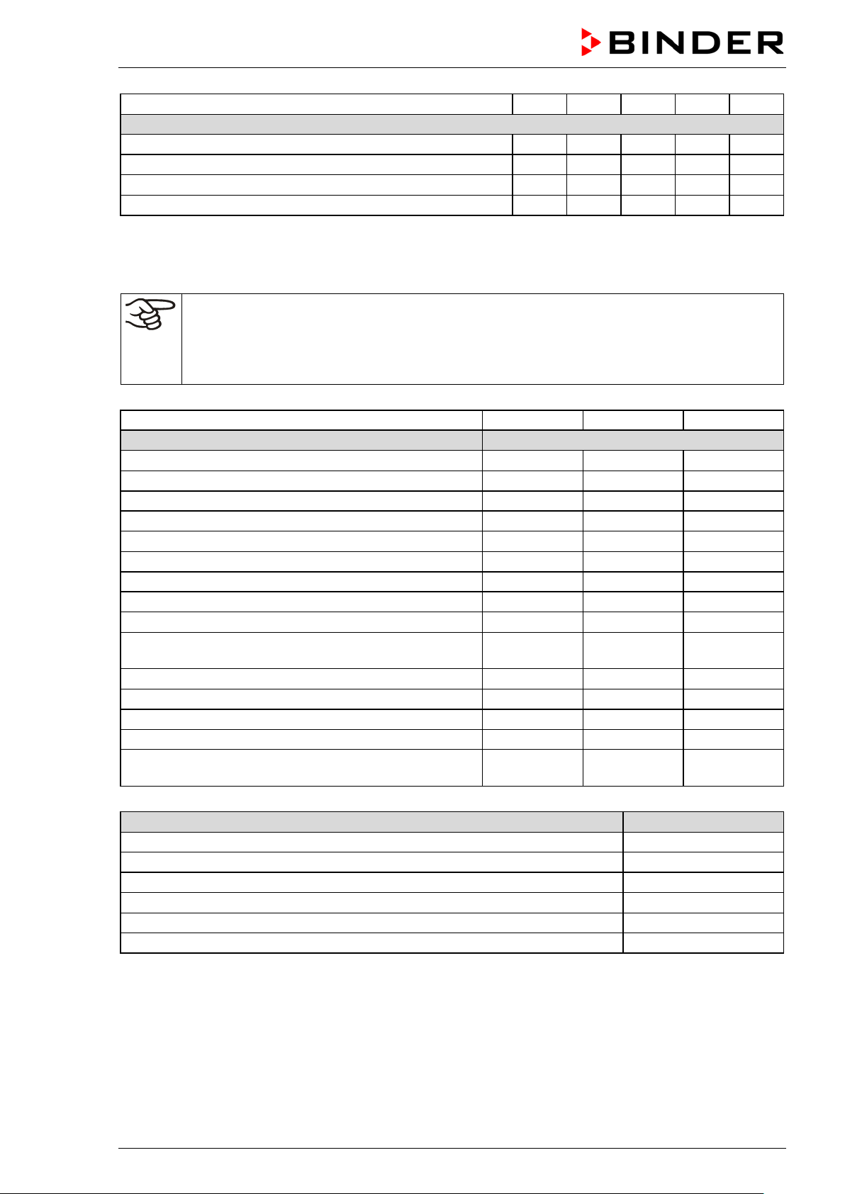
BD
BF
ED
FD
FED
Options / accessories (continued)
Measuring protocol acc. to DIN 12880:2007
√ √ √ √ √
Qualification folder
√ √ √ √ √
Neutral cleaning agent (liquid concentrate)
√ √ √ √ √
Stable table on wheels with castors and lock ing brak es
√ √ √ √ √
Chamber size
56
115
260
Description
Art. No.
Rack, chrome-plated BD, ED
6004-0174
6004-0175
6004-0177
Rack, chrome-plated BF, FD, FED
6004-0166
6004-0169
Rack, stainless steel BD, ED
6004-0158
6004-0159
6004-0161
Rack, stainless steel BF, FD, FED
6004-0150
6004-0151
6004-0153
Perforated rack, stainless steel BD, ED
6004-0190
6004-0191
6004-0193
Perforated rack, stainless steel BF, FD, FED
6004-0182
6004-0183
6004-0185
Rack, heavy load, stainless steel BD, ED
6004-0201
6004-0202
6004-0203
Rack, heavy load, stainless steel BF, FD, FED
6004-0198
6004-0199
6004-0200
Door gasket silicone
6005-0254
6005-0255
6005-0258
Door gasket made of FKM (temperature resistant up to
200 °C / 392 °F max.)
Stable table on wheels with castors and lock ing brak es
9051-0005
9051-0005
9051-0006
Chamber fuse 5x20mm 250V 6,3 A time lag (T)
---
Chamber fuse 5x20mm 250V 8,0 A time lag (T)
---
---
5006-0093
Chamber fuse 5x20mm 250V 12,5 A time lag (T)
5006-0096
5006-0096
5006-0096
External housing with HEPA Fresh air filter, class H 14
(DIN EN 1822:2009)
Description
Art. No.
HEPA fresh air filter (replacement) class H 14 (DIN EN 1822:2009)
6014-0003
Rubber pads for safe stacking (4 pieces)
8012-0001
Data Logger kit T 220
8012-0715
Data Logger kit T 350
8012-0714
Data Logger software
8012-0821
Neutral cleaning agent, 1 kg
1002-0016
16.10 Accessories and spare parts (extract)
BINDER GmbH is responsible for the safety features of the chamber only, provided skilled
electricians or qualified personnel authorized by BINDER perform all maintenance and repair,
and if components relating to chamber safety are replaced in the event of failure with original
spare parts. The user is responsible for any risks arising from using unauthorized accessories/components.
6004-0167
6005-0265 6005-0266 6005-0268
5006-0092
5006-0092
8012-1050 8012-1051 8012-1052
For information on components not listed here, please contact BINDER Service.
BD / BF / ED / FD / FED (E3.1) 07/2017 page 75/99
Page 76

Chamber type
BD
BF
ED
FD
FED
Validation service
Art.-No.
Qualification folder IQ-OQ
8012-0870
8012-0871
8012-0761
8012-0792
8012-0855
Qualification folder IQ-OQ-PQ
8012-0958
8012-0959
8012-0942
8012-0943
8012-0944
Execution of IQ-OQ
DL400100
DL400100
DL400100
DL400100
DL400100
Execution of IQ-OQ-PQ
DL440500
DL440500
DL440500
DL440500
DL440500
Chamber type
BD
BF
ED
FD
FED
Calibration service
Art.-No.
Calibration of temperature including certificate (1 measuring point)
certificate (9 measuring points)
Spatial temperature measurement including
certificate (18 measuring points)
Spatial temperature measurement including
certificate (27 measuring points)
Measurement of air ventilation acc. to ASTM
D 5374, including certificate
DL300101 DL300101 DL300101 DL300101 DL300101
Spatial temperature measurement including
DL300109 DL300109 DL300109 DL300109 DL300109
DL300118 DL300118 DL300118 DL300118 DL300118
DL300127 DL300127 DL300127 DL300127 DL300127
-- -- DL330000 DL330000 DL330000
BD / BF / ED / FD / FED (E3.1) 07/2017 page 76/99
Page 77
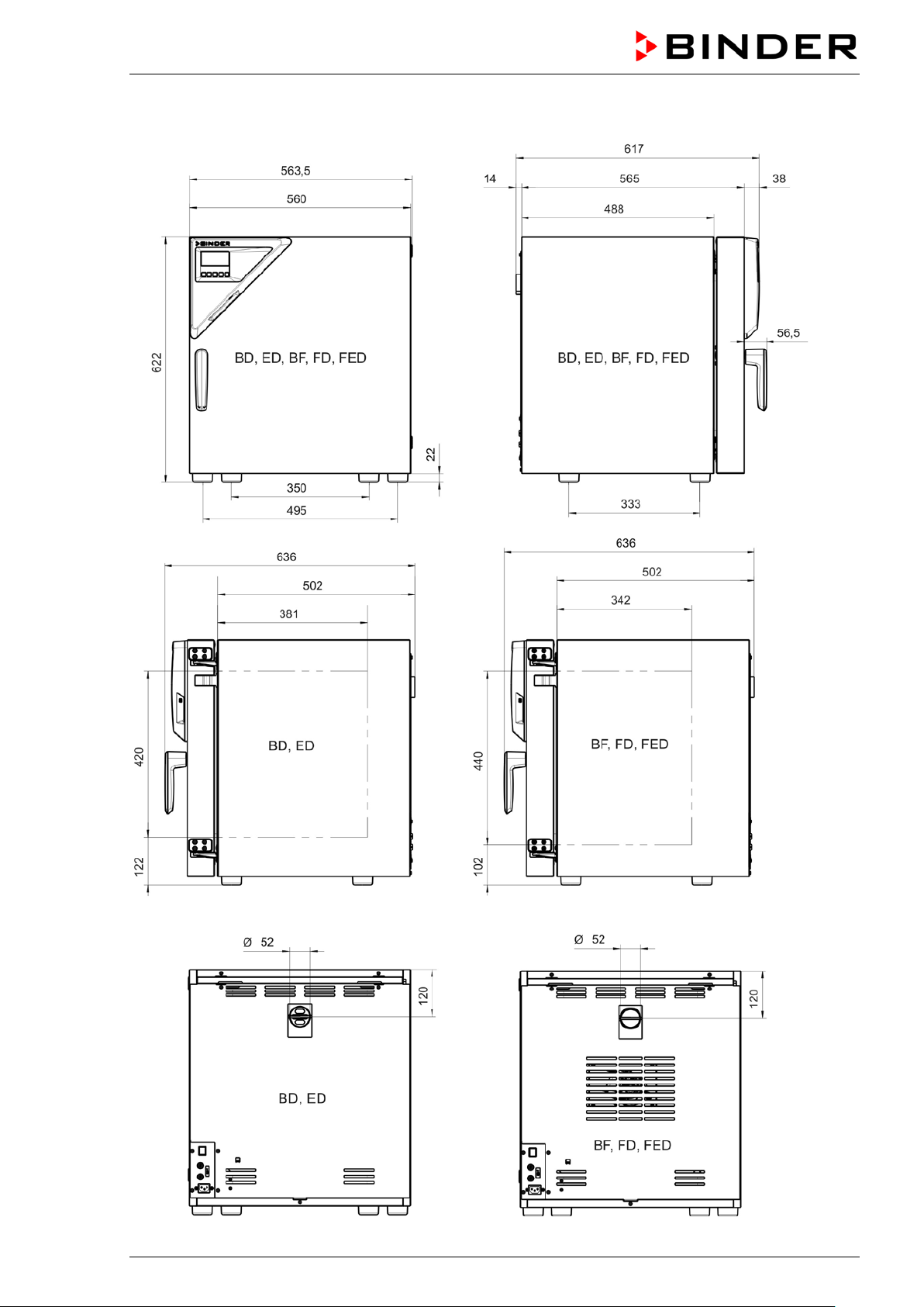
16.11 Dimensions size 56
BD / BF / ED / FD / FED (E3.1) 07/2017 page 77/99
Page 78
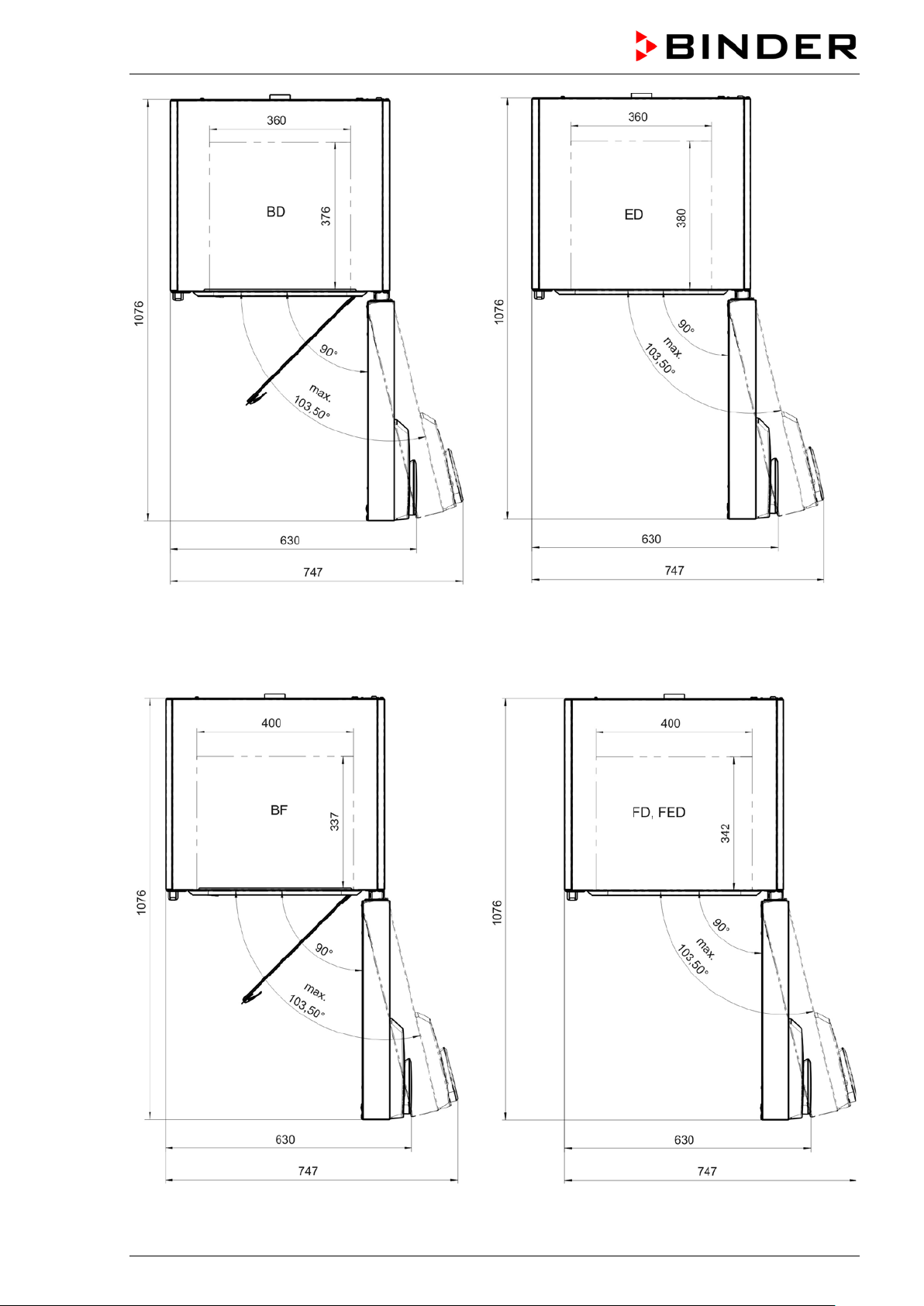
BD / BF / ED / FD / FED (E3.1) 07/2017 page 78/99
Page 79

16.12 Dimensions size 115
BD / BF / ED / FD / FED (E3.1) 07/2017 page 79/99
Page 80
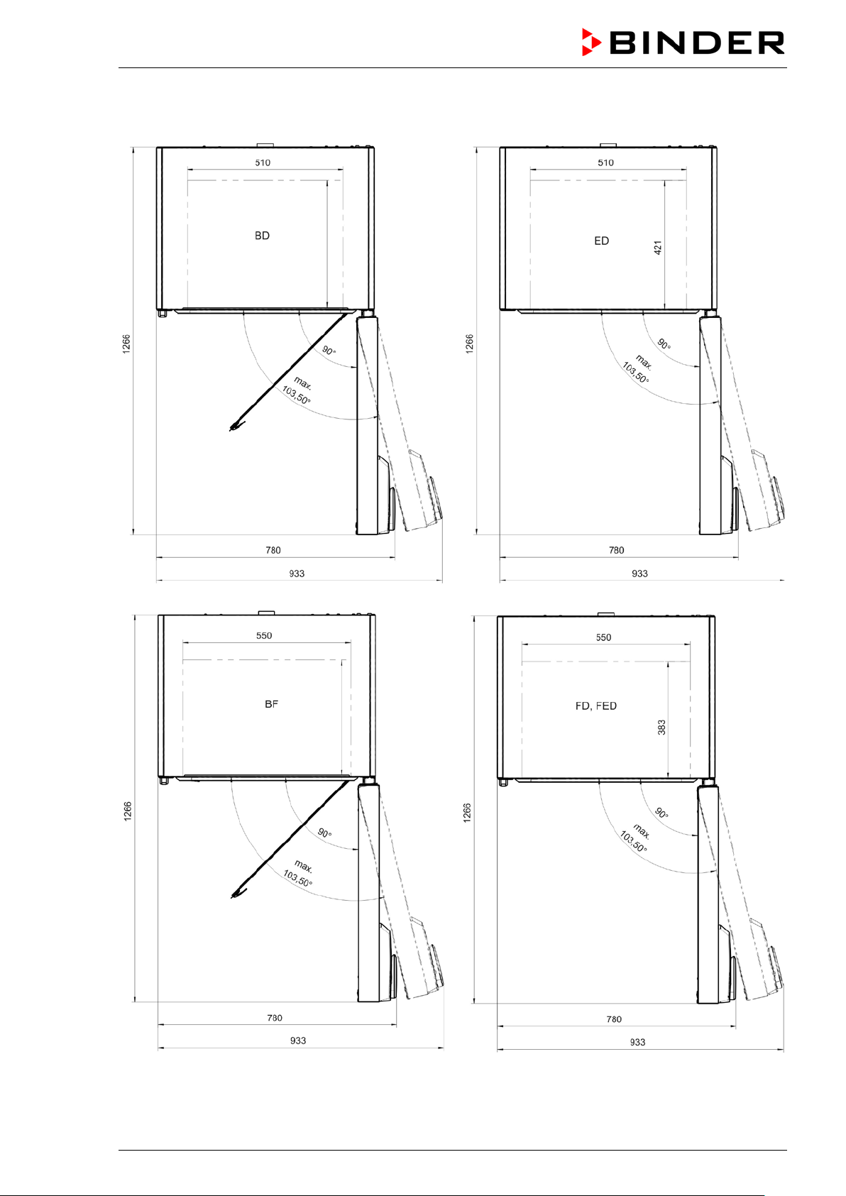
BD / BF / ED / FD / FED (E3.1) 07/2017 page 80/99
Page 81
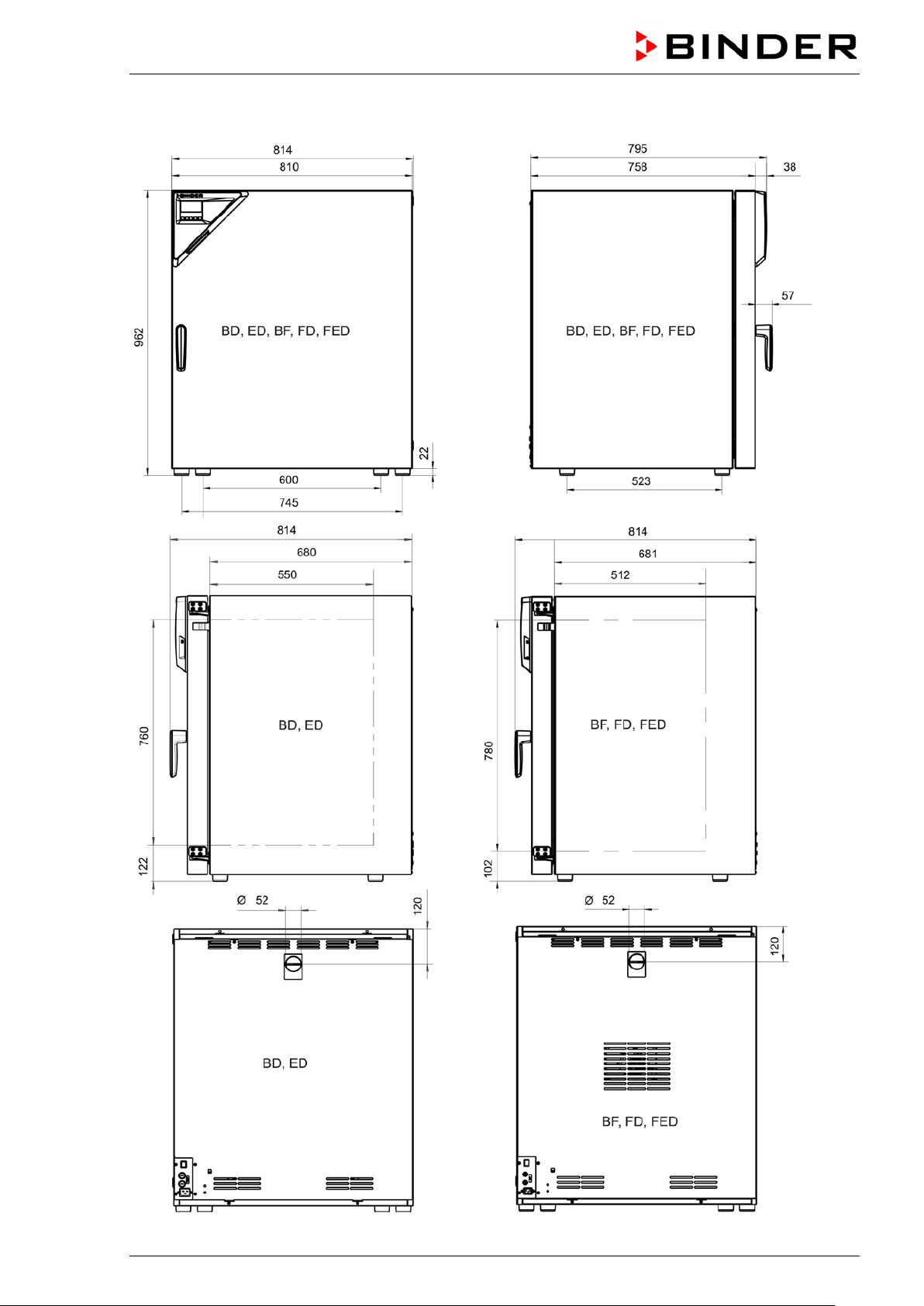
16.13 Dimensions size 260
BD / BF / ED / FD / FED (E3.1) 07/2017 page 81/99
Page 82
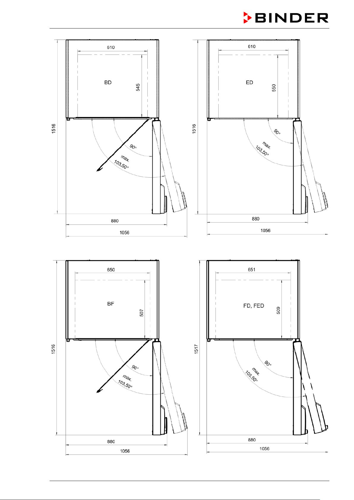
BD / BF / ED / FD / FED (E3.1) 07/2017 page 82/99
Page 83

17. Certificates and declarations of conformity
17.1 EU Declaration of Conformity for BD
BD / BF / ED / FD / FED (E3.1) 07/2017 page 83/99
Page 84

BD / BF / ED / FD / FED (E3.1) 07/2017 page 84/99
Page 85

17.2 E U Declaration of Conformity for BF
BD / BF / ED / FD / FED (E3.1) 07/2017 page 85/99
Page 86

BD / BF / ED / FD / FED (E3.1) 07/2017 page 86/99
Page 87

17.3 E U Declaration of Conformity for ED
BD / BF / ED / FD / FED (E3.1) 07/2017 page 87/99
Page 88

BD / BF / ED / FD / FED (E3.1) 07/2017 page 88/99
Page 89

17.4 E U Declaration of Conformity for FD
BD / BF / ED / FD / FED (E3.1) 07/2017 page 89/99
Page 90

BD / BF / ED / FD / FED (E3.1) 07/2017 page 90/99
Page 91

17.5 E U Declaration of Conformity for FED
BD / BF / ED / FD / FED (E3.1) 07/2017 page 91/99
Page 92

BD / BF / ED / FD / FED (E3.1) 07/2017 page 92/99
Page 93

18. Product registration
BD / BF / ED / FD / FED (E3.1) 07/2017 page 93/99
Page 94

1. Chamber/ component part / type: / Gerät / Bauteil / Typ:
2. Serial No./ Serien-Nr.:
3. Details about utilized substances / biological substances / Einzelheiten über die eingesetzten
3.1 Designations / Bezeichnungen:
3.2 Safety measures required for handling these substances / Vorsichtsmaßnahmen beim Um-
19. Contamination clearance certificate
19.1 For chambers located outside the USA and Canada
Declaration with regard to safety and health
Erklärung zur Sicherheit und gesundheitlichen Unbedenklichkeit
The German Ordinance on Hazardous Substances (GefStofV), and the regulat ions regarding safety at
the workplace, require tha t this f orm be filled out for all products that are retur ned to us, so that the s afet y
and health of our employees can be warranted.
Die Sicherheit und Gesundheit unserer Mitarbeiter, die Gefahrstoffverordnung GefStofV und die Vorschriften zur
Sicherheit am Arbeitsplatz machen es erforderlich, dass dieses Formblatt für alle Produkte, die an uns zurückgeschickt wird.
In the absence of a completely filled out form, a repair is not possible.
Ohne Vorliegen des vollständig ausgefüllten Formblattes ist eine Reparatur nicht möglich.
• A completely filled out f orm should be transmitted b y Fax (+49 (0) 7462 2005 93555) or by letter in
advance to us, so that this information is available before the equipment/component part arrives. A
second copy of this form should accompany the equipment/component part. Eventually the carrier
should be informed.
Eine vollständig ausgefüllte Kopie dieses Formblattes soll per Telefax (Nr. +49 (0) 7462 2005 93555) oder Brief
vorab an uns gesandt werden, so dass die Information vorliegt, bevor das Gerät/Bauteil eintrifft. Eine weitere Kopie soll dem Gerät/Bauteil beigefügt sein. Ggf. ist auch die Spedition zu informieren.
Incomplete inform ation or non-conform ity with this procedur e will inevitabl y lead to substantia l delays
•
in processing. We hope you will have unders tandin g for this meas ure, which lies outs ide of our area of
influence, and that you will help us to speed up this procedure.
Unvollständige Angaben oder Nichteinhalten dieses Ablaufs führen zwangsläufig zu beträchtlichen Verzögerungen in der Abwicklung. Bitte haben Sie Verständnis für Maßnahmen, die außerhalb unserer Einflussmöglichkeiten
liegen und helfen Sie mit, den Ablauf beschleunigen.
Please fill out this form completely.
•
Bitte unbedingt vollständig ausfüllen!
Substanzen/biologische Materialien:
a) ____________________________________________________________________________
b) ____________________________________________________________________________
c) ____________________________________________________________________________
gang mit diesen Stoffen:
a) ____________________________________________________________________________
b) ____________________________________________________________________________
c) ____________________________________________________________________________
BD / BF / ED / FD / FED (E3.1) 07/2017 page 94/99
Page 95

3.3 Measures to be taken in case of skin con tact or release into th e atmosphere / Maßnahmen
3.4 Other important information that must be taken into account / Weitere zu beachtende und
4. Declaration on the risk of these substances (please checkmark the applicable items) /
4.1 For non toxic, non radioactive, biologically harmless materials / für nicht giftige, nicht radio-
Wir versichern,
weder giftige noch
evtl. Rückstände von Gefahrstoffen
4.2 For toxic, radioactive, biologically harmful or hazardous substances, or any other ha-
für giftige, radioaktive, biologisch bedenkliche bzw. gefährliche Stoffe oder
, in 3.1 aufgelistet
das Gerät/Bauteil nicht mit
5. Kind of transport / transporter / Transportweg/Spediteur:
bei Personenkontakt oder Freisetzung:
a) ____________________________________________________________________________
b) ____________________________________________________________________________
c) ____________________________________________________________________________
d) ____________________________________________________________________________
wichtige Informationen:
a) ____________________________________________________________________________
b) ____________________________________________________________________________
c) ____________________________________________________________________________
Erklärung zur Gefährlichkeit der Stoffe (bitte Zutreffendes ankreuzen) :
aktive, biologisch ungefährliche Stoffe:
We herewith guarantee that the above-mentioned chamber / component part… /
dass o.g. Gerät/Bauteil...
Has not be en exposed t o or cont ains an y toxic or o therwise ha zardous s ubstances /
sonstige gefährliche Stoffe enthält oder solche anhaften.
That eventually gener ated reaction products are non-toxic and a lso do not represent a ha zard /
evtl. entstandene Reaktionsprodukte weder giftig sind noch sonst eine Gefährdung darstellen.
auch
Eventual residues of hazardous substances have been removed /
entfernt wurden.
zardous materials /
anderweitig gefährliche Stoffe.
We herewith guarantee that … /
Wir versichern, dass …
The hazardous substances, which have come into contact with the above-mentioned equip-
ment/component part, ha ve been completely listed u nder item 3.1 and that all inform ation in this regard is complete /
sind und alle Angaben vollständig sind.
die gefährlichen Stoffe, die mit dem o.g. Gerät/Bauteil in Kontakt kamen
That the chamber /component part has not been i n contac t with radio acti vity /
Radioaktivität in Berührung kam
Transport by (means and name of transport company, etc.) Versendung durch (Name Spediteur o.ä.)
___________________________________________________________________________________
Date of dispatch to BINDER GmbH / Tag der Absendung an BINDER GmbH:
___________________________________________________________________________________
BD / BF / ED / FD / FED (E3.1) 07/2017 page 95/99
Page 96

We herewith declare that the following measures have been taken / Wir erklären, dass folgende
We herewith comm it ourselves and g uar an tee th at we will in demnify BINDER GmbH for all dam ages that
ir versichern, dass wir gegenüber BINDER
für jeden Schaden, der durch unvollständige und unrichtige Angaben entsteht, haften und BINDER gegen eventuell
We are aware that, i n ac c o rdanc e with Ar t icle 823 of the Germ an Ci vi l C ode (BGB), we are direct l y liab le
hier insbesondere mit der Handhabung/Reparatur des Geräts/des Bauteils betraute Mitarbeiter der Firma
Maßnahmen getroffen wurden:
Hazardous substances were removed from the chamber / component part, so that no hazard exists for
corresponding persons in the handling or repair of these items /
fen befreit, so dass bei Handhabung/Reparaturen für die betreffenden Person keinerlei Gefährdung besteht
das Gerät/Bauteil wurde von Gefahrstof-
The chamber was sec urely packaged and pr operly identified /
ständig gekennzeichnet.
das Gerät wurde sicher verpackt und voll-
Inform ation about the ha zardousness of the shipm ent (if required) has be en provided to th e transpor-
der Spediteur wurde (falls vorgeschrieben) über die Gefährlichkeit der Sendung informiert.
ter /
are a consequence of incomplete or incorrect information provided by us, and that we will exempt
BINDER GmbH fr om eventual dam age claim s by third part ies./
entstehende Schadenansprüche Dritter freistellen.
W
with regard to third par ties, in this instanc e espec ially the emplo yees of BIND ER Gm bH, who have b een
entrusted with the han dling / repair of the chamber / com ponent. /
Dritten –
BINDER - gemäß §823 BGB direkt haften
Es ist uns bekannt, dass wir gegenüber
Name: _______________________________________________________________________
Position: _______________________________________________________________________
Datum: _______________________________________________________________________
Date /
Signature / Unterschrift: ______________________________________________________________
Company stamp /
Firmenstempel:
Equipment that is returned to the factory for repair must be accompanied by a completely filled
out contamination clearance certificate. For service and maintenance works on site, such a
contamination clearance certificate must be submitted to the service technician before the
start of the works. No repair or maintenance of the equipment is possible, without a properly
filled out contamination clearance certificate.
BD / BF / ED / FD / FED (E3.1) 07/2017 page 96/99
Page 97

19.2 For chambers located in the USA and Canada
Product Return Authori zation Request
Please complete this f orm and the Custom er Decontam ination Declarat ion (next 2 pages ) and attach the
required pictures. E-mail to: IDL_SalesOrderProcessing_USA@binder-world.com
After we have received and reviewed the complete information we will decide on the issue of a RMA
number. Please be aware that s ize specifications, voltage spec ifications as well as perf ormance specifications are available on the internet at www.binder-world.us at any time.
Take notice of shipping laws and regulations.
Please fill:
Reason for return request Duplicate order
Duplicate shipment
Demo
Power Plug / Voltage 115V / 230 V / 208 V / 240V
Size does not fit space
Transport Damage
Other (specify below)
_____________________
Is there a replacement PO? Yes No
If yes -> PO #
If yes -> Date PO placed
Purchase order number
BINDER model number
BINDER serial number
Date chamber was received
Was the chamber unboxed? Yes No
Was the chamber plugged
in?
Yes No
Page one completed by sales
Shock watch tripped? (pictures)
Was the chamber in operation?
Pictures of chamber attached?
Pictures of Packaging attached?
Customer Contact Information Distributor Contact Information
Name
Company
Address
Phone
E-mail
BD / BF / ED / FD / FED (E3.1) 07/2017 page 97/99
Yes No
Yes No
Yes No
Pictures have to be attached!
Page 98

1. Chamber/ component part / type
2. Serial No.
3. List any exposure to hazardous liquids, gasses or substances and radioactive material
3.1 List with MSDS sheets attached where available or needed
3.2 Safety measures required for handling the list under 3.1
3.3 Measures to be taken in case of skin contact or release into the atmosphere
3.4 Other important information that mus t b e considered
Customer (End User) Dec ont ami na tion Declaration
Health and Hazard Safety declaration
To protect the hea lth of our emplo yees and the safet y at the w orkplace, we requir e that t his form is completed by the user f or al l products and parts th at are returned to us . ( D is trib utor s or Ser vic e Or gan i zat ions
cannot sign this form)
NO RMA number will be issued without a completed form. Products or parts returned to our
NY warehouse without a RMA number will be refused at the dock.
A second copy of the completed form must be attached to the outside of the shipping box.
:
(if there is not enough space available below, please attach a page):
a) ____________________________________________________________________________
b) ____________________________________________________________________________
c) ____________________________________________________________________________
a) ____________________________________________________________________________
b) ____________________________________________________________________________
c) ____________________________________________________________________________
a) ____________________________________________________________________________
b) ____________________________________________________________________________
c) ____________________________________________________________________________
d) ____________________________________________________________________________
:
a) ____________________________________________________________________________
b) ____________________________________________________________________________
c) ____________________________________________________________________________
:
BD / BF / ED / FD / FED (E3.1) 07/2017 page 98/99
Page 99
4. Declaration of Decontamination
For toxic, radioactive, biologically and chemically harmful or hazardous substances, or any other
I hereby commit and guarantee that we will indemnify BINDER Inc. for all damages that are a
hazardous materials.
We hereby guarantee that
4.1 Any hazardous substances, which have come into contact with the above-mentioned equipment /
component part, have been completely listed under item 3.1 and that all information in this regard is
complete
.
4.2 That the chamber /component part has not been in contact with radioactivity
4.3 Any Hazardous substances were removed from the chamber / component part, so that no hazard
exists for a persons in the shipping, handling or repair of these returned chamber
4.4 The chamber was securely packaged in the original undamaged packaging and properly identified
on the outside of the packaging material with the chamber designation, the RMA number and a
copy of this declaration.
4.5 Shipping laws and regulations have not been violated.
consequence of incomplete or incorrect information provided by us, and that we will indemnify
and hold harmless BINDER Inc. from eventual d amage claims by third parties.
Name: _______________________________________________________________________
Position: _______________________________________________________________________
Company: _______________________________________________________________________
Address: _______________________________________________________________________
Phone #: _______________________________________________________________________
Email: _______________________________________________________________________
Date: _______________________________________________________________________
Signature: _______________________________________________________________________
Equipment returned to the NY warehouse for repair must be accompanied by a completed
customer decontamination declaration. For service and maintenance works on site, such a
customer decontamination declaration must be submitted to the service technician before the
start of work. No repair or maintenance of the equipment is possible without a completed form.
BD / BF / ED / FD / FED (E3.1) 07/2017 page 99/99
 Loading...