

Page 1
Operating Manual
Translation of the original operating manual
BD / BD-UL (E2) – Incubators with natural convection
ED / ED-UL (E2) – Drying and heating ovens with natural convection
FD / FD-UL (E2) – Drying and heating ovens with forced convection
with microprocessor temperature controller
Modell Model version Art. No. Modell Model version Art. No.
BD 23
BD 53
BD 115
BD 240
BD400
BD720
ED 23
ED 53
BD023-230V 9010-0187
ED 240
BD023UL-120V 9010-0189 ED240UL-208V 9010-0167
BD053-230V 9010-0081
ED400
BD053UL-120V 9010-0179 ED400UL-208V 9010-0168
BD115-230V 9010-0088
ED720
BD115UL-120V 9010-0181 ED720UL-208V 9010-0169
BD240-230V 9010-0095
FD 23
BD240UL-120V 9010-0183 FD023UL-120V 9010-0196
BD400-230V 9010-0073
FD 53
BD400UL-120V 9010-0176 FD053UL-120V 9010-0128
BD720-230V 9010-0074
FD 115
BD720UL-120V 9010-0177 FD115UL-120V 9010-0129
ED023-230V 9010-0190/0191
FD 240
ED023UL-120V 9010-0192/0193 FD240UL-208V 9010-0130
ED053-230V 9010-0078/0079
ED053UL-120V 9010-0131/0132
ED240-230V 9010-0101
ED400-230V 9010-0075
ED720-230V 9010-0076
FD023-230V 9010-0194
FD053-230V 9010-0082
FD115-230V 9010-0102
FD240-230V 9010-0104
ED 115
ED115-230V 9010-0096/0097
ED115UL-120V 9010-0164/0165
BINDER GmbH
Address: Post office box 102, 78502 Tuttlingen, Germany Phone: +49 7462 2005 0
Fax: +49 7462 2005 100 Internet: http://www.b ind er -world.com
E-mail: info@binder-world.com Service Hotline: +49 7462 2005 555
Service Fax: +49 7462 2005 93 555 Service E-Mail: service@binder-world.com
Service Hotline USA: +1 866 885 9794 or +1 631 224 4340 x3
Service Hotline Asia Pacif ic: +852 390 705 04 or +852 390 705 03
Service Hotline Russia and CIS: +7 495 988 15 16
Issue 03/2019 Art. No. 7001-0026
Page 2

Content
1. SAFETY .................................................................................................................. 4
1.1 Legal considerations ........................................................................................................................... 4
1.2 Structure of the safety instructions ...................................................................................................... 4
1.2.1 Signal word panel .......................................................................................................................... 4
1.2.2 Safety alert symbol ........................................................................................................................ 5
1.2.3 Pictograms ..................................................................................................................................... 5
1.2.4 Word message panel structure ...................................................................................................... 6
1.3 Localization / position of safety labels on the chamber ...................................................................... 6
1.4 Type plate............................................................................................................................................ 7
1.5 General safety instructions on installing and operating the chambers ............................................... 8
1.6 Intended use ..................................................................................................................................... 10
1.7 Operating instructions ....................................................................................................................... 11
1.8 Measures to prevent accidents ......................................................................................................... 11
2. CHAMBER DESCRIPTION .................................................................................. 12
2.1 Chamber overview ............................................................................................................................ 13
3. COMPLETENESS OF DELIVERY, TRANSPORTATION, STORAGE, AND
INSTALLATION .................................................................................................... 13
3.1 Unpacking, and checking equipment and completeness of delivery ................................................ 13
3.2 Guidelines for safe lifting and transportation ..................................................................................... 14
3.3 Storage .............................................................................................................................................. 14
3.4 Location of installation and ambient conditions ................................................................................ 15
4. INSTALLATION OF THE EQUIPMENT ............................................................... 16
4.1 Electrical connection ......................................................................................................................... 16
4.2 Connection to a suction plant (optional) ............................................................................................ 17
5. START UP ............................................................................................................ 17
5.1 Turning on the chamber .................................................................................................................... 17
5.2 Heating operation display.................................................................................................................. 17
5.3 Air change ......................................................................................................................................... 18
6. OPERATING THE CONTROLLER ....................................................................... 18
6.1 Display / entry of temperature set-point (without ramp function) ...................................................... 18
6.2 Display / entry of temperature set-point (with selected temperature ramp) ...................................... 19
6.3 Time functions: Continuous operation and Timer operation ............................................................. 20
6.3.1 Switching between “Continuous operation” and “Timer operation” ............................................. 21
6.3.2 Continuous operation ................................................................................................................... 21
6.3.3 Timer operation: Setting the tempering time ................................................................................ 22
6.4 User level settings ............................................................................................................................. 23
6.4.1 Temperature unit change between degrees Celsius °C and degrees Fahrenheit °F .................. 23
6.4.2 Entering a temperature ramp ....................................................................................................... 24
6.4.3 Chamber addressing .................................................................................................................... 24
6.5 General notes .................................................................................................................................... 25
7. TEMPERATURE SAFETY DEVICES ................................................................... 26
7.1 Temperature safety device class 2 (DIN 12880) ED, FD .................................................................. 26
7.2 Temperature safety device class 3.1 (DIN 12880) BD (option for ED, FD) ...................................... 27
BD / ED / FD (E2) 03/2019 page 2/68
Page 3

8. OPTIONS .............................................................................................................. 29
8.1 Disconnectable audible over-temperature alarm (option) ................................................................. 29
8.2 APT-COM™ 4 Multi Management Software (option for BD and ED) ............................................... 29
8.3 Data logger kit (option) ...................................................................................................................... 29
8.4 Additional Pt100 temperature sensor (option for BD) ....................................................................... 30
8.5 Analog output for temperature (option) ............................................................................................. 30
8.6 Water protected internal socket (option for BD) ................................................................................ 31
9. MAINTENANCE, CLEANING, AND SERVICE .................................................... 32
9.1 Maintenance intervals, service .......................................................................................................... 32
9.2 Cleaning and decontamination ......................................................................................................... 32
9.2.1 Cleaning ....................................................................................................................................... 33
9.2.2 Decontamination .......................................................................................................................... 34
9.3 Sending the chamber back to BINDER GmbH ................................................................................. 35
10. DISPOSAL............................................................................................................ 36
10.1 Disposal of the transport packing ...................................................................................................... 36
10.2 Decommissioning .............................................................................................................................. 36
10.3 Disposal of the chamber in the Federal Republic of Germany ......................................................... 36
10.4 Disposal of the chamber in the member states of the EU except for the Federal Republic of
Germany............................................................................................................................................ 37
10.5 Disposal of the chamber in non-member states of the EU ............................................................... 38
11. TROUBLESHOOTING ......................................................................................... 39
12. TECHNICAL DESCRIPTION ................................................................................ 40
12.1 Factory calibration and adjustment ................................................................................................... 40
12.2 Definition of usable volume ............................................................................................................... 40
12.3 Over current protection ..................................................................................................................... 40
12.4 BD technical data .............................................................................................................................. 41
12.5 ED technical data .............................................................................................................................. 42
12.6 FD technical data .............................................................................................................................. 44
12.7 Equipment and options BD (extract) ................................................................................................. 47
12.8 Equipment and options ED (extract) ................................................................................................. 48
12.9 Equipment and options FD (extract) ................................................................................................. 49
12.10 Accessories and spare parts (extract) .............................................................................................. 50
13. CERTIFICATES AND DECLARATIONS OF CONFORMITY ............................... 51
13.1 EU Declaration of Conformity for BD ................................................................................................ 51
13.2 EU Declaration of Conformity for ED ................................................................................................ 54
13.3 EU Declaration of Conformity for FD ................................................................................................ 57
13.4 Certificate for the GS mark of conformity of the “Deutsche Gesetzliche Unfallversicherung e.V.“
(German Social Accident Insurance) DGUV ..................................................................................... 60
14. PRODUCT REGISTRATION ................................................................................ 62
15. CONTAMINATION CLEARANCE CERTIFICATE ............................................... 63
15.1 For chambers located outside the USA and Canada ....................................................................... 63
15.2 For chambers located in the USA and Canada ................................................................................ 66
BD / ED / FD (E2) 03/2019 page 3/68
Page 4
Dear customer,
For the correct operation of the chambers, it is im portant that you read this operat ing manual com pletely
and carefully and observe all instructions as indicated. Failure to read, understand and follow the
instructions may result in personal injury. It can also lead to damage to the chamber and/or poor
equipment performance.
Understanding and obser ving the instructions in this operat ing manual are prerequisites for ha zard-free
use and safety during operation and maintenance. In no event shall BINDER be held liable for any
damages, direct or incidental arising out of or related to the use of this manual.
1. Safety
This operating manual is part of the components of delivery. Always keep it handy for reference. The
device should only be operated b y laboratory personnel especially trained f or this purpose and familiar
with all precautionar y measures require d for working i n a laborator y. Observe th e national regul ations on
minimum age of laborator y personn el T o avoid inj uries and dam age obser ve the saf et y instructions of the
operating manual.
WARNING
Failure to observe the safety instructions.
Serious injuries and chamber damage.
Observe the safety instructions in this operating manual
Carefully read the complete operating instructions of the chamber.
1.1 Legal considerations
This operating m anual is for informational purposes only. It contains information for ins talling, start-up,
operation and mainte nance of the product. Note: the contents and the pr oduct described are subjec t to
change without notice.
Understanding and obser ving the instructions in this operat ing manual are prerequisites for ha zard-free
use and safety during operation and maintenance. In no event shall BINDER be held liable for any
damages, direct or incidental arising out of or related to the use of this manual.
This operating manual can not cover all conce ivable applications . If you would like add itional inform ation,
or if special problem s arise that are not suff iciently addressed in th is manual, please ask your dealer or
contact us directly by phone at the number located on page one of this manual
Furthermore, we emphasize that the contents of this operating manual are not part of an earlier or
existing agreement, description, or legal relationship, nor do they modify such a relationship. All
obligations on the part of BINDER derive from the respective purchas e contract, which a lso contains the
entire and exclusivel y valid statement of warrant y administration. The statem ents in this manual neither
augment nor restrict the contractual warranty provisions.
1.2 Structure of the safety instructions
In this operating manual, the following safety definitions and symbols indicate dangerous situations
following the harmonization of ISO 3864-2 and ANSI Z535.6.
1.2.1 Signal word panel
Depending on the probability of serious consequences, potential dangers are identified with a signal
word, the corresponding safety color, and if appropriate, the safety alert symbol.
DANGER
Indicates an imminently hazardous situation that, if not avoided, will result in death or serious
(irreversible) injury.
BD / ED / FD (E2) 03/2019 page 4/68
Page 5
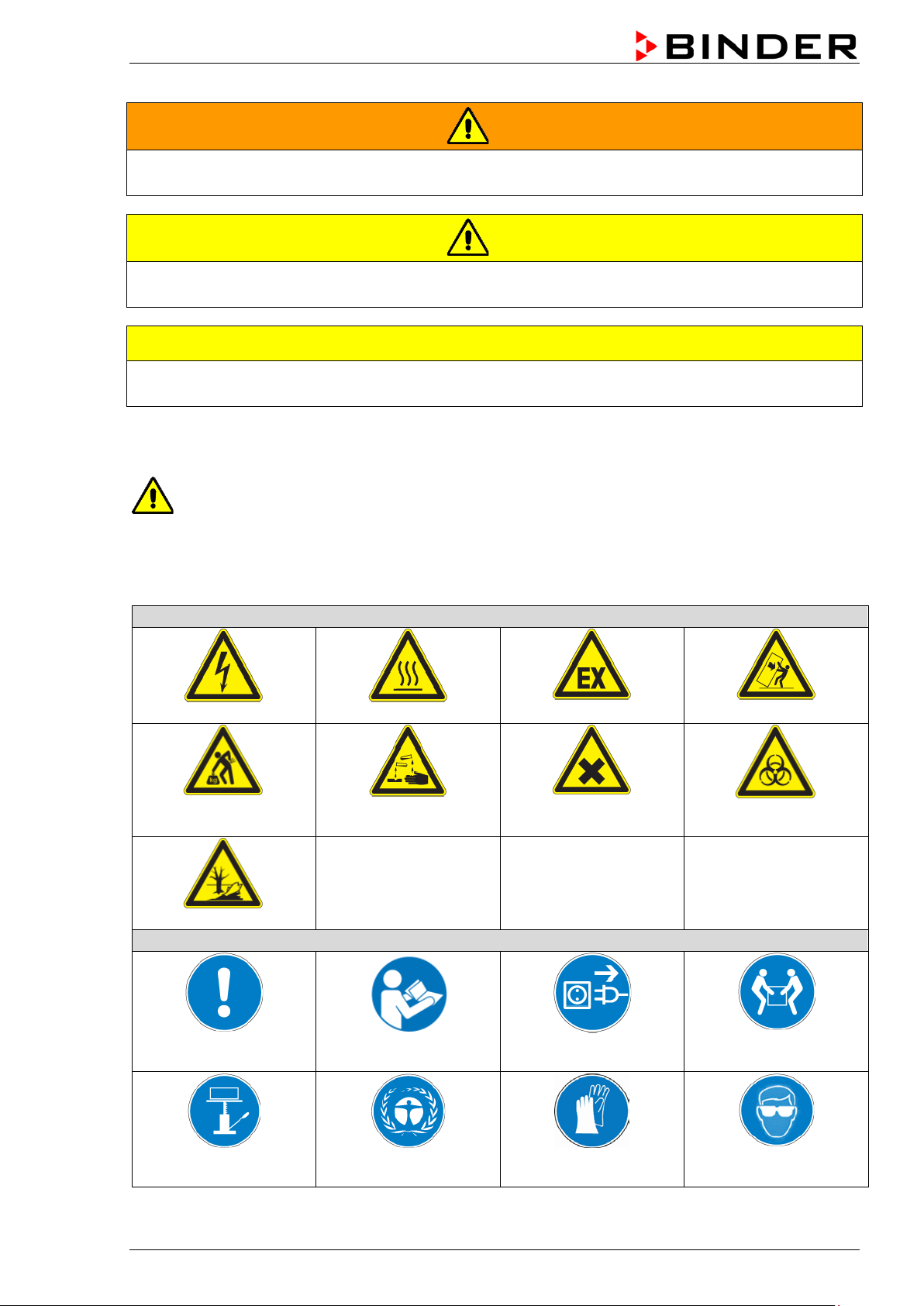
Warning signs
Electrical hazard
Hot surface
chemical burns
Pollution Hazard
Mandatory action signs
instructions
plug
assistance
WARNING
Indicates a potentially hazardous situation which, if not avoided, could result in death or serious
(irreversible) injury
CAUTION
Indicates a potentially hazardous situation which, if not avoided, may result in moderate or minor
(reversible) injury
CAUTION
Indicates a potentially hazardous situation which, if not avoided, may result in damage to the product
and/or its functions or of a property in its proximity.
1.2.2 Safety alert symbol
Use of the safety alert symbol indicates a risk of injury.
Observe all measures that are marked with the safety alert symbol in order to avoid death or
injury.
1.2.3 Pictograms
Lifting hazard
Mandatory regulation
Risk of corrosion and / or
Read operating
Explosive atmosphere
Harmful substances
Disconnect the power
Stability hazard
Biohazard
Lift with several persons
Lift with mechanical
BD / ED / FD (E2) 03/2019 page 5/68
Environment protection Wear protective gloves
Wear safety goggles
Page 6
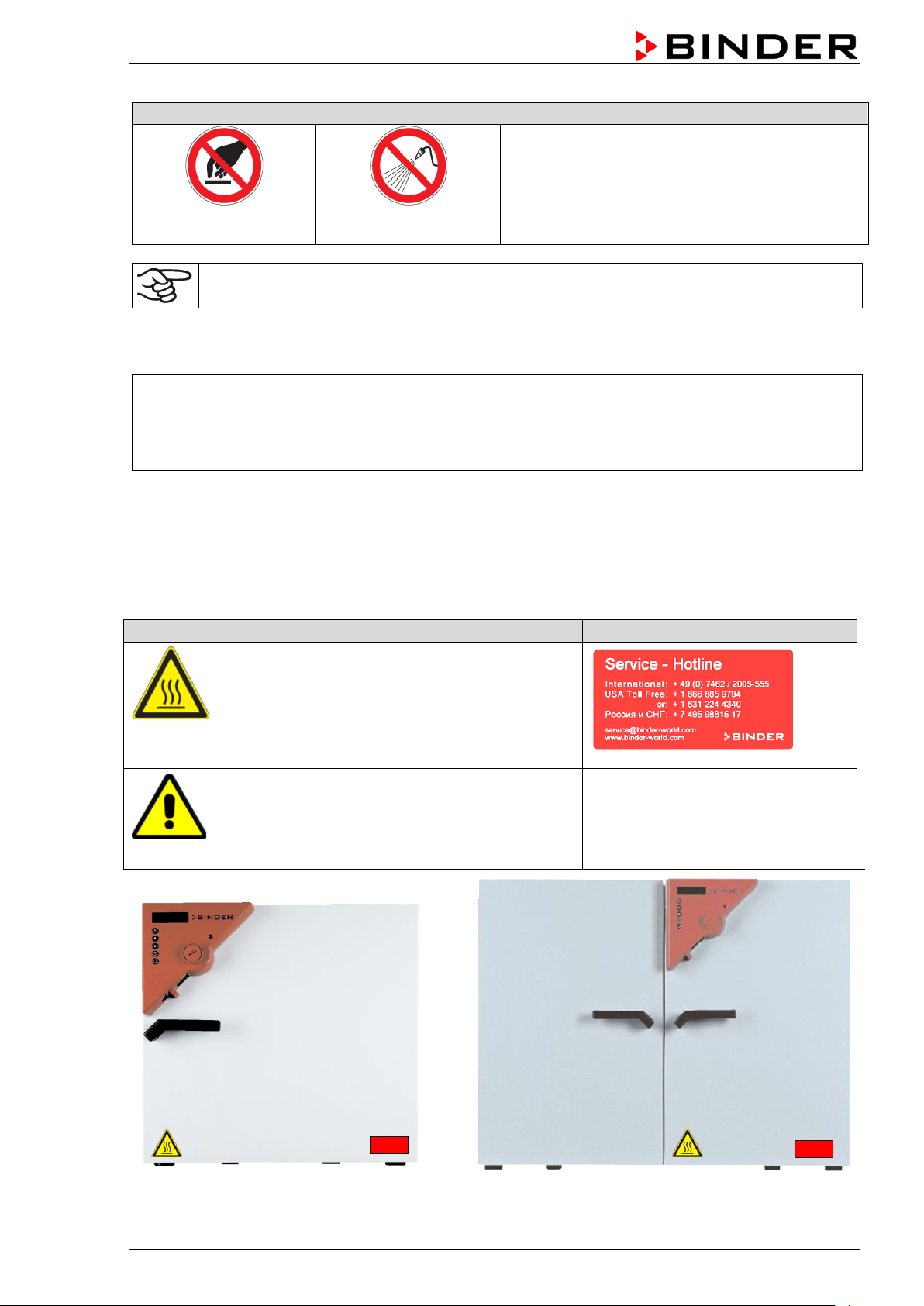
Prohibition signs
water
Pictograms (Warning signs)
Service label
Hot surface
Do NOT touch
Do NOT spray with
Information to be observed in order to ensure optimum function of the product.
1.2.4 Word message panel structure
Type / cause of hazard.
Possible consequences.
∅ Instruction how to avoid the hazard: prohibition.
Instruction how to avoid the hazard: mandatory action.
Observe all other notes and inf ormation not necessarily emphasi zed in the same way, in order to avoid
disruptions that could result in direct or indirect injury or property damage.
1.3 Localization / position of safety labels on the chamber
The following labels are located on the chamber:
• ED, FD: outer chamber door
• BD: inner glass door next to the glass door
handle
• On chamber rear next to the exhaust duct
Read operating manual
• UL chambers: outer chamber door
• BD with optional interior socket: below the
interior socket
BD / ED / FD (E2) 03/2019 page 6/68
Figure 1: Position of labels on the chamber on the front (example: ED, FD)
Page 7
Indications of the type plate (example)
Information
BINDER
Manufacturer: BINDER GmbH
FD 115
Model designation
Incubator
Device name: Incubator
Drying and heating oven
Device name: Drying and heating oven
Serial No.
000000000000
Serial No.
Built
2019
Year of construction
100 °C
212 °F
IP protection
20
IP type of protection acc. to EN 60529
Class
3.1
Class of temperature safety device
Art. No.
9110-0081
Art. no. of the chamber
Project No.
---
Optional: Special application acc. to project no.
Nominal temp.
300 °C
1,60 kW / 7,0 A
572 °F
230 V / 50 Hz
IP protection
20
230 V / 60 Hz
Safety device
DIN 12880
1 N ~
Class
2.0
Art. No.
9010-0102
Project No.
Built
2019
Drying and heating oven
BINDER GmbH
www.binder-world.com
FD 115
E2
Serial No. 00000000000000
Nominal temp.
100 °C
0,40 kW / 1,8 A
With option internal socket:
212 °F
230 V / 50 Hz
Nominal power: 0,90 kW
IP protection
20
230 V / 60 Hz
Safety device
DIN 12880
1 N ~
Class
3.1
Art. No.
9010-0081
Built
2019
Incubator
BINDER GmbH
www.binder-world.com
BD 53
E2
Serial No. 00000000000000
Keep safety labels complete and legible.
Replace safety labels that are no longer legible. Contact BINDER Service for these replacements.
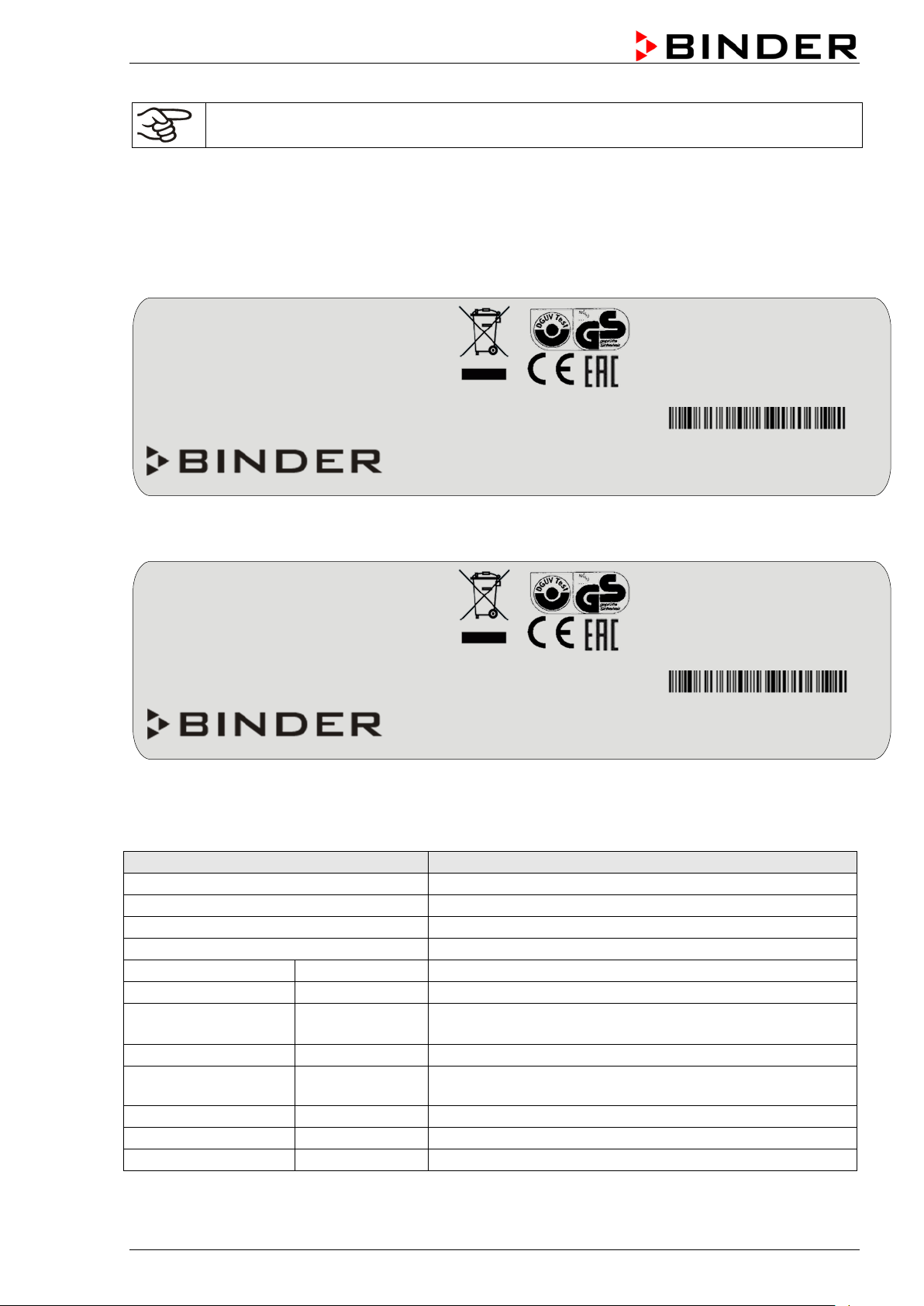
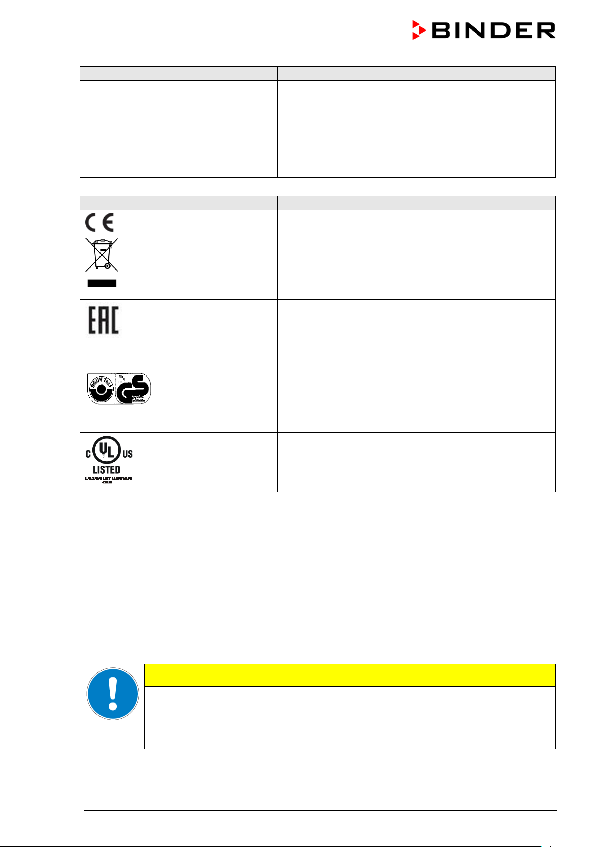
1.4 Type plate
The type plate is locat ed on the left-hand side of the chamber (size 23) or on th e chamber front behind
the door, bottom left-hand.
Im Mittleren Ösch 5
78532 Tuttlingen / Germany
Figure 2: Type plate (example: FD 115 regular chamber)
Made in Germany
Project No.
Im Mittleren Ösch 5
78532 Tuttlingen / Germany
Made in Germany
Figure 3: Type plate (example: BD 53 optional chamber)
Nominal temperature
Temp. safety device DIN 12880
BD / ED / FD (E2) 03/2019 page 7/68
Nominal temperature
Temperature safety device acc. to standard DIN
12880:2007
Page 8
Indications of the type plate (example)
Information
0,40 kW
Nominal power
1,8 A
Nominal current
230 V / 50 Hz
230 V / 60 Hz
1 N ~
Current type
With option internal socket:
Nominal power: 0,90 kW
Symbol on the type plate
Information
Nominal voltage +/-10% at the indicated power frequency
With option internal socket: increased total nominal power
CE conformity marking
Electrical and electronic equipment manufactured / placed
on the market in the EU after 13 August 2005 and to be
disposed of in a separate collection according to directive
2012/19/EU on waste electrical and electronic equipment
(WEEE).
The chamber is certified according to Customs Union
Technical Regulation (CU TR) for the Eurasian Economic
Union (Russia, Belarus, Armenia, Kazakhstan Kyrgyzstan).
GS mark of conformity of the “Deutsche Gesetzliche
Unfallversicherung e.V. (DGUV), Prüf- und
Zertifizierungsstelle Nahrungsmittel und Verpackung im
DGUV Test“ (German Social Accident Insurance (DGUV),
Testing and Certification Body for Foodstuffs and
Packaging Industry in DGUV Test).
Not valid for UL chambers
®
(UL chamber only)
The chamber is certified by Underwriters Laboratories Inc.
according to the following standards:
st
UL 61010A-1, 1
Edition, UL 61010A-2-10, 1st Edition
CSA C22.2 No. 1010.1-92, IEC 1010-2-10
1.5 General safety instructions on installing and operating the chambers
With regard to operating the chambers and to the installation location, please observe the DGUV
guidelines 213-850 on safe working in laboratories (form erly BGI/GUV-I 850-0, BGR/GUV-R 120 or ZH
1/119, issued by the employers’ liability insurance association) (for Germany).
BINDER GmbH is only responsible for the s afety features of the chamber provided sk illed electricians or
qualified personnel authorized by BINDER perform all maintenance and repair, and if components
relating to chamber safety are replaced in the ev ent of failure with original spare parts.
To operate the chamber, use only original BINDER ac cessories or ac cessories from third-party supp liers
authorized by BINDER. The user is responsible for any risk caused by using unauthorized accessories.
Danger of overheating.
Damage to the chamber.
∅ Do NOT install the chamber in unventilated recesses.
Ensure sufficient ventilation for dispersal of the heat.
BD / ED / FD (E2) 03/2019 page 8/68
CAUTION
Page 9
Do not operate the chambers in hazardous locations.
DANGER
Explosion hazard.
Danger of death.
∅ Do NOT operate the chamber in potentially explosive areas.
KEEP explosive dust or air-solvent mixtures AWAY from the chamber.
The chambers do not dispose of any measures of explosion protection.
DANGER
Explosion hazard.
Danger of death.
∅ Do NOT introduce any substance into the chamber which is combustible or explosive at
working temperature.
∅ NO explosive dust or air-solvent mixture in the inner chamber.
Any solvent contained in th e charging material m ust not be explosive or inflamm able. I.e., irrespect ive of
the solvent concentrati on in the steam room, NO explosi ve mixture with air must form. The temper ature
inside the chamber mus t lie below the flash point or below th e sublimation po int of the charging m aterial.
Familiarize yourself with the physical and chemical properties of the charging material, as well as the
contained moisture constituent and its behavior with the addition of heat energy.
Familiarize yourself with any potential health risks caused by the charging material, the contained
moisture constituent or by reaction products that may arise during the temperature process. Take
adequate measures to exclude such risks prior to putting the chamber into operation.
DANGER
Electrical hazard.
Danger of death.
∅ The chamber must NOT become wet during operation or maintenance.
The chambers were produced in accordance with VDE regulations and were routinely tested in
accordance to VDE 0411-1 (IEC 610 10-1).
During and shortly after operation, the temperature of the inner surfaces almost equals the set-point.
CAUTION
The glass doors and glass door handles (BD), inner chamber, exhaust duct, door
window (option), and the door gaskets will become hot during operation.
Danger of burning.
∅ Do NOT touch the glass doors, inner surfaces, exhaust duct, door window, access
ports, door gaskets, or the charging material during operatio n.
BD / ED / FD (E2) 03/2019 page 9/68
Page 10

1.6 Intended use
The chambers are s uitable f or ex act tem pering of har m less m ater ials a nd f or dr yin g and h eat tr e atment of
solid or pulverized c h argi ng material, as well as bulk material, using the supply of heat. They can b e use d
to dry e.g. glassware, and for warm storage of liquids in containers.
Because of their precise t emperature accurac y the incubators BD are especial ly useful for incubation of
cultures at a standard temperature of 37 °C / 98.6 °F.
A solvent content must not be explosive or flammable. A mixture of any component of the charging
material with air must NOT be explosive. The operating tem perature must lie below the flash point or
below the sublimatio n point of the char ging material. Any component of the charging mater ial must NOT
be able to release toxic gases
Other applications are not approved.
The chambers are not cl assified as medical devices as defined b y the Medical Device Di rective
93/42/EEC.
Do NOT use the chamber for drying processes when lar ge quantities of vapor would f orm and result in
condensation.
Due to the special demands of the Medical Device Directive 93/42/EEC, these chambers are
not qualified for sterilization of medical devices as defined by the directive.
Observing the instructions in this operating manual and conducting regular maintenance work
(chap. 9) is part of the intended use.
WARNING: If customer should use a BINDER chamber running in non-supervised
continuous operation, we strongly recommend in case of inclusion of irrecoverable specimen
or samples to split such specimen or samples and store them in at least two chambers, if this
is feasible.
The charging material shall not contain any corrosive ingredients that may damage the
machine components. Such ingredients include in particular acids and halides. Any corrosive
damage caused by such ingredients is excluded from liability by BINDER GmbH.
The chambers do not dispose of any measures of explosion protection.
DANGER
Explosion or implosion hazard.
Danger of poisoning.
Danger of death.
∅ Do NOT introduce any substance combustible or explosive at working temperature into
the chamber, in particular no energy sources such as batteries or lithium-ion batteries.
∅ NO explosive dust or air-solvent mixture in the inner chamber.
∅ Do NOT introduce any substance which could lead to release of toxic gases.
In case of foreseeable use of the device there is no risk for the user through the integration of the
chamber into systems or by special environmental or operating conditions in the sense of EN 610101:2010. For this, the intended use of the chamber and all its connections must be observed.
BD / ED / FD (E2) 03/2019 page 10/68
Page 11

1.7 Operating instructions
Depending on the a pplicati on and loc ation of the cha m ber, the operator of the chamber must prov ide the
relevant information for safe operation of the chamber in a set of operating instructions.
Keep these operating instructions with the chamber at all times in a place where they are
clearly visible. They must be comprehensible and written in the language of the employees.
1.8 Measures to prevent accidents
The manufacturer took the follo wing m easur es to prevent ign iti on and expl os io ns:
• Indications on the type plate
See operating manual chap. 1.4.
• Operating manual
An operating manual is available for each chamber.
• Overtemperature monitoring
The chamber is equipped with a temperature display, which can be read from outside.
The chamber is equipped with an additional safety controller (temperature safety device class 3.1 (BD)
or class 2 (ED, FED) acc. to DIN 12880:2007). Visual and audible (buzzer) signals indicate
temperature exceeding.
• Safety, measurement, and control equipment
The safety, measuring, and control equipment is easily accessible.
• Electrostatic ch arg e
The interior parts are grounded.
• Non-ionizing radiation
Non-ionizing radiation is not intentionally produced, but released only for technical reasons by
electrical equipm ent (e.g. electric motors, power cables, solenoids). The m achine has no permanent
magnets. If persons with active implants (e.g. pacemakers, defibrillators) keep a safe distance
(distance of field sourc e to i mplant) of 30 cm, an influence of thes e implants can be excluded with h igh
probability.
• Protection against touchable surfaces
Tested according to EN ISO 13732-1:2008.
• Floors
See operating manual chap. 3.4 for correct installation
• Cleaning
See operating manual chap. 9.2.
• Examinations
The chamber has been inspected by the “Deutsche Gesetzliche Unfallversicherung e.V. (DGUV)
(German Social Accident Insurance (DGUV)” (German Social Accident Insurance (DGUV), Testing
and Certification Body for Foodstuffs and Packaging Industry i n DGUV Test) and bears the GS m ark.
(Not valid for UL chambers)
®
UL chambers only: The chamber is certified by Underwriters Laboratories Inc.
standards UL 61010A-1, 1
st
Edition, UL 61010A-2-10, 1st Edition, CSA C22.2 No. 1010.1-92, IEC
according to the
1010-2-10.
BD / ED / FD (E2) 03/2019 page 11/68
Page 12

2. Chamber description
BINDER incubators BD and drying and heating ovens ED and FD are equipped with an electronic PIDcontroller with digital displa y.
The incubators BD indicate the temperature with an accuracy of a tenth of a degree.
The drying and heating ovens ED and FD indicate the temperature with an accuracy of one
degree.
The chambers are heated electrically. Incubators BD and drying and heating ovens ED are ventilated
naturally. Drying and heati n g ovens FD are ventilated by fan-assisted, forced-air circulation.
The APT.line™ preheating cham ber s ystem guarantee s high level of s patial a nd tim e-based tem perature
precision, thanks to the direct and distributed a ir circulation into the interior . With FD, the fan supports
exact attainment and maintenance of the desired temperature accuracy.
The chambers are regularly equipped with a temperature safety device according to DIN12880:2007
(chap. 7).
The inner chamber, the pre-heating chamber and the inside of the doors are all made of stainless s teel
V2A (German material no. 1.4301, US equivalent AISI 304). When operating the drying and heating
ovens ED an d FD at t emper atures abov e 150 °C / 302 °F, the impact of the oxyg en in the air ma y cause
discoloration of the metallic surfaces (yellowish-brown or blue) by natural oxidation processes. These
colorations are harmles s and will in no way impair the function or quality of the chamber. The housing is
RAL 7035 powder-coated. All corners and edges are also completely coated.
All chamber f unctions are easy and comfor table to use thanks to their cle ar arrangem ent. Major f eatures
are easy cleaning of all chamber parts and avoidance of undesired contamination.
BINDER incubators BD and drying and heating ovens ED ( opt ion) ar e eq uip ped with a s erial interface RS
422 for computer com munication, e.g. via t he APT-COM™ 4 Mu lti Management Sof tware (option, chap.
8.2). For further options, see chap. 12.7 to 12.9.
The models size 720 are equipped with
Temperature range at an ambient temperature of +18 °C up to +40 °C / 64.4 °F to 104 °F.
• Incubators BD: 5 °C / 9 °F above room temperature up to 100 °C / 212 °F.
• Drying and heating ovens ED and FD: 5 °C / 9 °F above room temperature up to 300 °C / 572 °F.
four castors. Both front castors can be locked by brakes.
BD / ED / FD (E2) 03/2019 page 12/68
Page 13

(1) Display
(6)
(9)
(7)
(8)
(10)
(1)
2.1 Chamber overview
(2) Set-point value key
(3) Selector keys
(4) Time management key
(5) Sw itch ON/OFF
(6) Lever for ventilation slide
(7) Safety device
(8) Door handle
(9) BD: ON/OFF switch for internal
socket (option)
ED / FD: Switch for interior
lighting (option) or
buzzer switch for audible overtemperature alarm (option)
(10) BD: Buzzer switch for audible
over-temperature alarm (option)
ED: Main power switch with
sizes 400 and 720
(2)
(3)
(4)
(5
)
Figure 4: Overview BD / ED / FD
3. Completeness of delivery, transportation, storage, and
installation
3.1 Unpacking, and checking equipment and completeness of delivery
After unpacking, p lease check the chamber and its optio nal accessories, if any, based on th e delivery
receipt for completenes s and for transportation damage. Inf orm the carrier immediately if trans portation
damage has occurred.
The final tests of the m anufacturer m ay have caused tr aces of the rack s on the inner surfac es. This has
no impact on the function and performance of the chamber.
Please remove any transportation pr otection devices and adhes ives in/on the chamber and on the doors
and take out the operating manuals and accessory equipment.
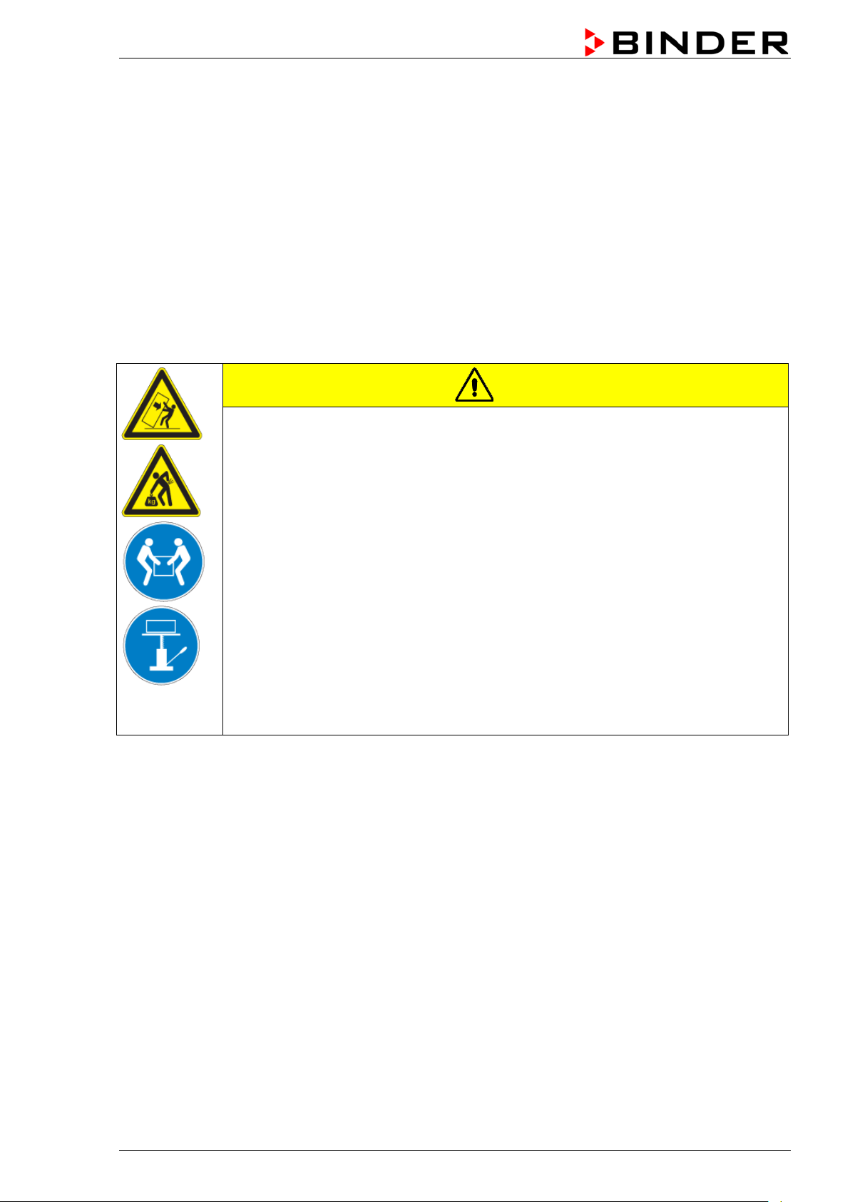
CAUTION
Sliding or tilting of the chamber.
Damage to the chamber.
Risk of injury by lifting heavy loads.
∅ Do NOT lift or transport the chamber using the door handle or the door.
∅ Do NOT lift chambers s ize 400 and 720 b y hand
Lift chambers size 23, 53, 115 from the pallet at its four lower corners
with the aid of 2 people, chamber size 240 with the aid of 4 people.
Lift chambers size 400 and 720 from the pallet using technical devices
(fork lifter). Set the fork lifter only from the rear in the middle of the
chamber. Make sure to place all the lateral supports of the chamber on
the forks.
If you need to return the chamber, please use the original packing and observ e the guidelines for safe
lifting and transportation (chap. 3.2).
BD / ED / FD (E2) 03/2019 page 13/68
Page 14
•
For disposal of the transport packing, see chap. 10.1.
Note on second-hand chambers (Ex-Demo chambers):
Second-hand chambers are chambers that have bee n used for a short time for tests or ex hibitions. The y
are thoroughly tested before res ale. BI NDER ens ures that the c ham ber is technic all y sound and will work
flawlessly.
Second-hand chambers are marked with a stick er on the chamber door. Please remove the s ticker before
commissioning the chamber.
3.2 Guidelines for safe lifting and transportation
The front castors of chambers size 720 can be blocked by brakes. Please move the chambers with
castors only when empty and on an even surface, otherwise the castors may be damaged. After
operation please observe the guidelines for temporarily decommissioning the chamber (chap. 10.2).
CAUTION
Sliding or tilting of the chamber.
Damage to the chamber.
Risk of injury by lifting heavy loads.
Transport the chamber only in its original packaging.
Secure the chamber with transport straps for transport.
∅ Do NOT lift or transport the chamber using the door handle or the door.
∅ Do NOT lift chambers s ize 400 and 720 b y hand.
Lift chambers size 23, 53, 115 at its four lower corners with the aid of 2 people,
chamber size 240 with the aid of 4 people, and place it on a transport pallet with
wheels. Push the pallet to the desired site and then lift the chamber from the pallet at
its four lower corners.
Place chambers size 400 and 720 using technical devices (fork lifter) on the
transport pallet. Set the fork lifter only from the rear in the middle of the chamber.
Make sure to place all the lateral supports of the chamber on the forks.
Transport chambers size 400 and 720 ONLY with the original transport pallet. Set
the fork lifter only to the pallet. Without the pallet the chamber is in imminent danger
of overturning!!
Permissible ambient temperature range during transport: -10 °C to +60 °C / 14 °F to 140 °F.
You can order transport packing and pallets for transportation purposes from BINDER Service.
3.3 Storage
Intermediate storage of the chamber is possible in a closed and dr y room. Observe the guidelines for
temporary decommissioning (chap. 10.2).
• Permissible ambient temperature range during storage: -10 °C to +60 °C / 14 °F to 140 °F.
• Permissible ambient humidity: max. 70 % r.H., non-condensing
When after storage in a cold location you transfer the chamber to its warmer installation site,
condensation ma y form. Before start-up, wait at least one hour until the chamber has attained am bient
temperature and is completely dry.
BD / ED / FD (E2) 03/2019 page 14/68
Page 15
•
•
•
3.4 Location of installation and ambient conditions
Set up the chamber on an even and non-flammable surface, free from vibration and in a well-ventilated,
dry location and align it using a spirit level. The site of installation must be capable of supporting the
chamber’s weight (see technical data, chap. 12.4 to 12.6). The chambers are designed for setting up
inside a building (indoor use).
CAUTION
Danger of overheating.
Damage to the chamber.
∅ Do NOT set up the chamber in non-ventilated recesses.
Ensure sufficient ventilation for dispersal of the heat.
Permissible ambient temperature range during operation: +18 °C up to +40 °C / 64.4 °F to 104 °F.
At elevated ambient temperature values, fluctuations in temperature can occur.
The ambient temperature should not be substantially higher than the indicated ambient
temperature of +25 °C / 77 °F to which the specified technical data relate. For other
ambient conditions, deviations from the indicated data are possible.
Permissible ambient humidity: 70 % r.H. max., non-condensing.
• Installation height: max. 3000 m / 9842 ft. above sea level.
When placing several chambers of the sam e size sid e by side, m ainta in a m inimum distanc e of 250 m m /
9.84 in between each chamber. Wall distances: rear 100 mm / 3.94 in, sides 160 mm / 6.30 in. Spacing
above the chamber of at least 100 mm / 3.94 in must also be accounted for.
Two chambers up to size 115 can be stacked on top of each other. For this purpose place rubber pads
under all four feet of the upper chamber to prevent the device from slipping.
CAUTION
Sliding or tilting of the upper chamber.
Damage to the chambers.
When stacking, place rubber pads under all four feet of the upper chamber.
To completely separate the chamber from the power supply, you must dis connect the power plug. Inst all
the chamber in a way that the power plug is easily accessible and can be easily pulled in case of danger.
For the user there is no risk of temporary overvoltages in the sense of EN 61010-1:2010.
Do not install or operate the chamber in potentially explosive areas.
DANGER
Explosion hazard.
Danger of death.
∅ Do NOT operate the chamber in potentially explosive areas.
KEEP explosive dust or air-solvent mixtures AWAY from the vicinity of the chamber.
BD / ED / FD (E2) 03/2019 page 15/68
Page 16
indicated power frequency
•
4. Insta llation of the equipment
4.1 Electri cal co nn ect io n
The chambers are supplied ready for connect ion. They come with a fixed p ower connection cable of at
least 1800 mm / 70.87 in in length.
Model Power plug
BD all sizes
ED 23 / 53 / 115 / 240
FD all sizes
ED 400 / 720 CEE plug 5 poles
BD 23-UL / 53-UL /
115-UL / 240-UL /
400-UL
ED 23-UL
FD 23-UL
BD 720-UL
ED 53-UL / 115-UL
FD 53-UL / 115-UL
ED 240-UL / 400-UL /
720-UL
FD 240-UL
The dom estic socket must also provide a protective conductor. Make sure that t he connection of the
protective conductor of the domestic installations to the chamber’s protective conductor meets the
latest technology. The protective conductors of the socket and plug must be compatible!
Grounded plug
NEMA 5-15P 115 V at 60 Hz 1N~
NEMA- 5-20P 115 V at 60 Hz 1N~
NEMA L21-20P 208 V at 60 Hz 3N~
Nominal voltage ± 10% at the
230 V at 50 Hz
230 V at 60 Hz
400 V at 50 Hz
400 V at 60 Hz
Current type
1N~
3N~
• Prior to con nection and s tar t-up, chec k the power supply voltage. Com pare t he values to the spec ified
data located on the chamber’s type plat e (chamber front behind t he door bottom left-hand, or on the
left-hand side of the chamber, chap. 1.4).
• When connecting, please observe the regulations specified by the local electricity supply company
and as well as the VD E directives (for Germ any). We recom mend the use of a residual curr ent circuit
breaker.
• Pollution degree (acc. to IEC 61010-1): 2
• Over-voltage category (acc. to IEC 61010-1): II
CAUTION
Danger of incorrect power supply voltage.
Damage to the equipment.
Check the power supply voltage before connection and start-up.
Compare the power supply voltage with the data indicated on the type plate.
See also electrical data (chap. 12.4 to 12.6).
To completely separate the chamber from the power supply, you must disconnect the power
plug. Install the chamber in a way that the power plug is easily accessible and can be easily
pulled in case of danger.
BD / ED / FD (E2) 03/2019 page 16/68
Page 17
The green “Standby“ LED illuminates
If the chamber is operating (time functions “Continuous operation”, or
), the
The heating and fan (with FD) are active as soon as the red heating
4.2 Connection to a suction plant (optional)
When directly connec ting a suction plant ; the spatial temperatur e exactitude, the heating-up times, the
recovering times , and the maximum temperature will be ne gativ ely inf luenced. So no s ucti on pla nt should
be directly connected to the exhaust duct.
Active suction from the chamber must only be effected together with extraneous air. Perforate
the connecting piece to the suction device or place an exhaust funnel at some distance to the
exhaust duct.
CAUTION
The exhaust duct will become hot during ope ration.
Danger of burning.
∅ Do NOT touch the exhaust duct during operati on.
5. Start up
5.1 Turning on the chamber
Warming chambers may release odors in the first few days after commissioning. This is not a
quality defect. To reduce odors quickly we recommend heating up the chamber to its nominal
temperature for one day and in a well-ventilated location.
1. Insert the plug int o a suitable socket (chap. 4.1).
2. Turn on ED chambers sizes 400 and 720 at the main power switch (10)
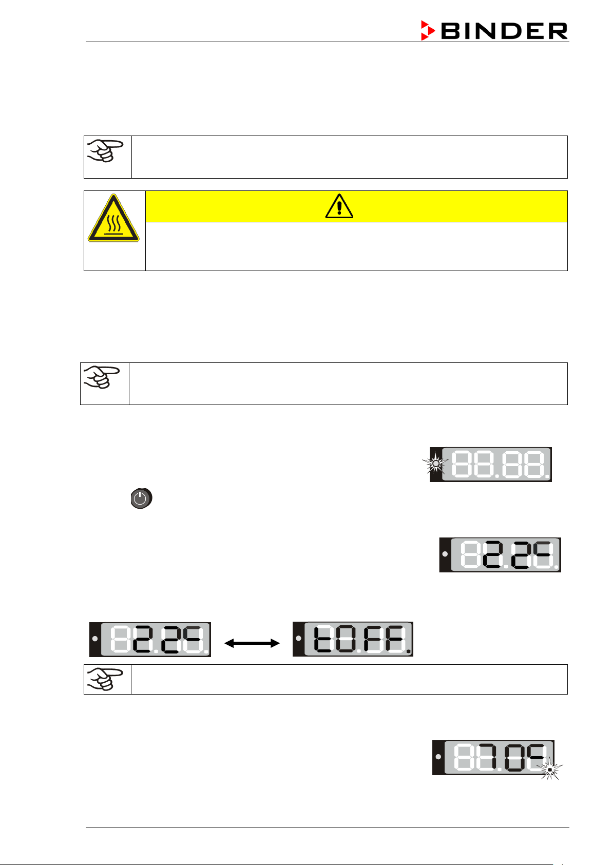
3. Press until the display lights up.
The controller is now in normal display (actual value display).
“Timer operation” with the set time just running down chap. 6.3
actual temperature value (example: 22 °C) is displayed
If the controller is in time function “Timer operation” with no time programmed or the set time run-off
(chap. 6.3), the chamber is inactive (no heating). T he display alternat ely shows the act ual temperature
value (example: 22 °C) and “tOff”:
Adjust the safety device following any changes of the set-point (chap. 7).
5.2 Heating operation display
control light in the bottom right corner of the display slowly begins to
flash depending on the heat requirement (example: 70 °C).
BD / ED / FD (E2) 03/2019 page 17/68
Page 18
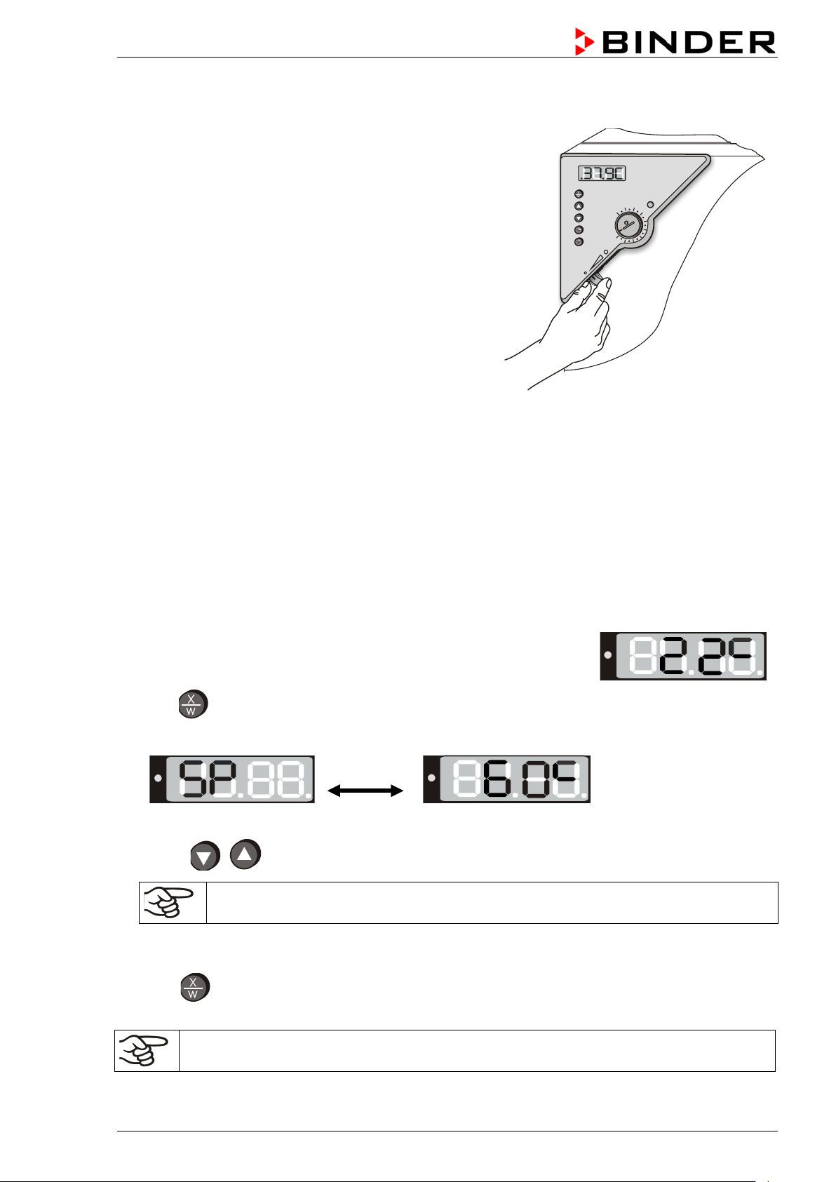
The chamber is operating, the controller is in norm al display (actual val ue
5.3 Air change
Opening the air flap in the exhaust duct serves to adjust the
air change.
Without connecting a suction plant:
• For BD and ED chambers fresh air circulation can be
elevated using the exhaust duct. The air flap in the
exhaust duct serves to adjust the fresh air entry.
• For FD chambers with the air flap open and the fan
operating, fresh air comes in via aeration gaps.
• If the air f lap is c ompletely open, the spa tia l t emperature
accuracy can be negatively influenced.
Figure 5: Adjusting the air flap
6. Opera ti ng t he c ontroller
Controller setting is identical with all thre e chambers BD, ED, an d FD. The temperature controllers onl y
differ in their temperature range (BD: up to 100 °C / 212 °F, ED/FD: up to 300 °C / 572 °F ) and the
displayed accuracy (BD: a tenth of a degree, ED/FD: one degree).
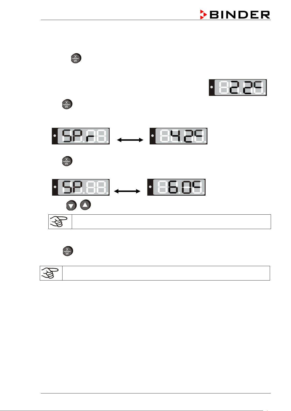
6.1 Display / entry of temperature set-point (without ramp function)
display). The actual temperature value (example: 22 °C) is displayed:
1. Press button
The display shows alternately “SP” and the previous temperature set-point (example: 60 °C):
2. With the buttons enter a set-point value between 0 and 300.
The desired temperature set-point can be selected in a temperature range from 5 °C / 9 °F
above room temperature up to 100 °C / 212 °F (BD) or 300 °C / 572 °F (ED/FD).
3. Wait 2
4. Press button to return to normal display (actual value display) (autom atically after approx. 30
seconds).
BD / ED / FD (E2) 03/2019 page 18/68
seconds until the entered temperature value is taken over (display flashing once).
Adjust the safety device following any changes of the set-point (chap. 7).
Page 19
The chamber is operating, the controller is in norm al display (actual val ue
6.2 Display / entry of temperature set-point (with selected temperature ramp)
If previously a temperature ramp value has been selected (chap. 6.4.2):
Press button in normal display / actua l value display during ram p operation to have displayed the
actual temperature ramp set-point, which chang es according to the selected gra dient, in addition to the
entered target set-point for temperature.
display). The actual temperature value (example: 22 °C) is displayed:
1. Press button
The display shows alter nately “SPr” and the actual te mperature ramp set-point changing according
to the selected gradient (example: 42 °C):
This ramp set-point is displayed only, it is not adjustable.
2. Press button
The display shows alternately “SP” and the previous temperature set-point (example: 60 °C):
3. With the buttons enter a set-point value between 0 and 300.
The desired temperature set-point can be selected in a temperature range from 5 °C / 9 °F
above room temperature up to 100 °C / 212 °F (BD) or 300 °C / 572 °F (ED/FD).
4. Wait 2
5. Press button to ret urn to normal display / actual value display (autom atically after approx. 30
seconds until the entered temperature value is taken over (display flashing once).
seconds).
Adjust the safety device following any changes of the set-point (chap. 7).
BD / ED / FD (E2) 03/2019 page 19/68
Page 20

Timer running
6.3 Time functions: Continuous operation and Timer operation
Press the time management button .
The timer indicates its current time function. There are two possible time functions:
Continuous operation
The display shows alternately “t1” (time function) and the time function “Continuous operation” “t inf”:
The heating and fan (with FD) are permanently active, independent of the timer setting.
Timer operation
The display shows alternately “t1” (time function) and the running-down time or “tOff”:
or
Press button to return to normal display (actual value display) (automatically after approx. 30
seconds).
Remaining time (example: 28 Min.) –
down
Heating and fan (with FD) are active until the timer has rundown.
Timer not programmed or run-down “t off”
If the timer has run-down, heating and fan (with FD) are
permanently off.
BD / ED / FD (E2) 03/2019 page 20/68
Page 21
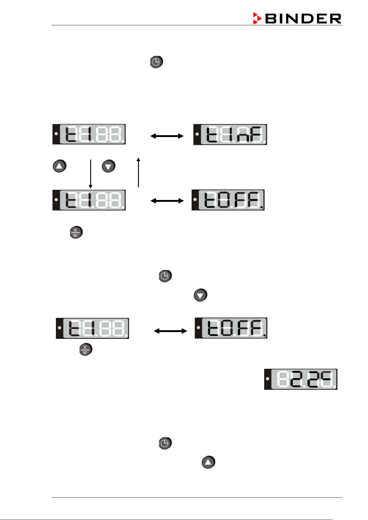
The actual temperature value (example: 22 °C) is displayed:
6.3.1 Switching between “Continuous operation” and “Timer operation”
Press the time management button .
The controller displays the actual time function. In time function “Continuous o peration”, “t1” and “t inf ” are
displayed alternately. In time function “Timer operation”, “t1” is displayed alternately with the runningdown time or “tOff”.
If in time function “Timer operation” the Timer is just running off (“t1”displayed alternately with the runningdown time) the timer m ust first be set to Zero (chap. 6.3.3). Now “t1” is displa yed alternately with “tOff”,
and the controller can be changed to time function “Continuous operation”.
Continuous operation
2 seconds
Timer operation
Press button to return to normal display / actual value display (automatically after approx. 30 sec).
2 seconds
Timer not programmed or run-down
6.3.2 Continuous operation
1. Press the time management button .The timer indicates its current time function.
2. If necessary, switch to timer operation by button .
The display shows alternately “t1” and the time function “Continuous operation” “t inf”:
3. Press button to return to normal display (actual value displa y) (automatically after approx. 30
seconds).
Now the controller o perates with the entered set-point (chap. 6.1) in continuo us operation. The heating
and fan (for FD) are permanently active, independent of the timer setting.
To cancel Continuous operation, proceed accordingly:
1. Press the time management button .
2. Switch to Timer operation by pressing down button for 2 seconds (chap. 6.3.1).
BD / ED / FD (E2) 03/2019 page 21/68
Page 22

The actual temperature value is displayed (example: 22 °C):
6.3.3 Timer operation: Setting the tempering time
1. Press the time management button . The controller indicates its current time function.
2. If necessary, switch to timer operation by button .
The display alternately shows”t1” and the running-down time or “tOff”:
or
3. Set the desired time [hh.mm] with buttons .
4. Wait 2 seconds until the entered temperature value is taken over (display flashing once).
The display alternately shows “t1” and the set time now running down.
The time directly begins to run off after taking-over of the entered value. Heati ng and fan (with FD) are
active until the timer has run-down.
5. Press button to return to normal display (actual value display) (automatically after approx. 30
seconds).
Remaining time (example: 28 minutes) – Timer
running down
Timer not programmed or run-off “t off”
The controller operates wit h the entered s et-p oints ( chap. 6.1) until run-down of the set t im e. Heating and
fan (with FD) are active until the timer has run-down.
To know the remaining timer time or, if appr opriate, to m odify it, press t he time management button
in normal display (actual value display).
The display alternately shows “t1” and the running-down time:
After the set time has run down the d ispl a y altern ate l y shows the actual temperat ure v alue (example: 22
°C) and “tOff”:
Now the heating and fan (with FD) are inactive.
BD / ED / FD (E2) 03/2019 page 22/68
Page 23

User level overview:
button for approx. 5
6.4 User level settings
By pressing down button in normal display (actual value display) for 5 sec, you enter the user menu.
Settings in this menu affect controller operation.
Press down button for approx. 5 seconds
Select the temperature unit (chap. 6.4.1)
Press button
Ramp function (chap. 6.4.2)
Press button
Setting the chamber address (chap. 6.4.3)
Press button to return to normal display with display of the temperature set-point. Or:
After approx. 30 seconds the controller automatically returns to normal display / actual value display.
All settings can be carried out independentl y (as desc ribed i n he in di vidue l s ectio ns ) or one af ter the other
during one single process.
The defined parameters are not deleted when the main power switch is turned off or in case
of power failure.
Figure 6: Press down
seconds
6.4.1 Temperature unit change between degrees Celsius °C and degrees Fahrenheit °F
If required, the temperature display can be changed as follows:
1. Press down button for approx. 5 seconds.
The display alternately shows “unit” and the actual setting of the temperature unit:
2. Use the buttons to set the required unit.
3. The set unit is automatically adopted after 2 seconds.
C = degrees Celsius
F= degrees Fahrenheit
When specifying the set point ramp (see chap. 6.4.2) this setting is accordingly taken as the basis.
If the unit is changed, the t emperature set-point and limits are converted accordingly.
BD / ED / FD (E2) 03/2019 page 23/68
0 °C = 31 °F
100 °C = 212 °F
Conversion:
[Value in °F] = [Value in °C] ∗ 1.8 + 32
Page 24

6.4.2 Entering a temperature ramp
You can program tem peratur e r amps in order to extend heating up times . This may be neces s ar y in some
cases to prevent tem perature stresses in the m aterial during the heati ng up phase. Temperatur e ramps
should only be used if required. Using them may result in considerably slowing down the heating up
times.
The entry in °C/min or in °F/min means the nom inal value gradient and lim its the maximum tem perature
increase to this value. D ue to the heat and evaporation energ y assumed by the drying mater ial, smaller
temperature gradients may also result.
A temperature ramp proceeds from a previously entered set-point to a new one. The temperature must be
equilibrated to the start set-point. Perform the setting in the following 3 steps:
1. Enter the set-point of the ramp start temperature. Let the temperature equilibrate to this value.
2. Set the ramp to the desired gradie nt. You can select a gradient f rom 0.0 °C/min up to 1.0 °C/min (BD),
resp. from 1 °C/min up to 10 °C/min (ED, FD).
A heating-up rate of 0.4 °C/min (BD) resp. 4 °C/min (ED, FD) can be regarded as a realistic maximum.
3. Enter the set-point (target ramp temperature).
Set a ramp gradient only if required. T he setting “0” means “ramp function turned of f”. The chamber will
heat up with its maximum heating capacity.
1. Press down button for approx. 5 seconds.
The display alternately shows “unit” and the temperature unit:
2. Press again button .
The display alternately shows “rASd” and the actual setting of the set-point gradient:
3. Set the desired ramp gradient with buttons (set-point gradient in °F or °C acc. to the
selected setting, see chap. 6.4.1).
4. The set value is automatically adopted after 2 seconds.
During ramp operation the ac tual set-point (SPr) continuall y rises in accordance to the entered gradient
from the previously entered set-point to the new one (SP). The actual value follows he set-point value.
About set-point display during ramp operation see chap. 6.2.
6.4.3 Chamber addressing
If several incubators BD or drying and heating ovens ED (option) are networked with a PC via the APTCOM™ 4 Multi Management Software (option, chap. 8.2), each chamber must be allocated a unique
address. Addressing takes place on the chamber controller as follows:
BD / ED / FD (E2) 03/2019 page 24/68
Page 25

1. Press down button for approx. 5 seconds.
The display alternately shows “unit” and the temperature unit:
2. Press again button .
The display alternately shows “rASd” and the set-point gradient:
3. Press again button .
The display alternately shows “Adr” and the actual setting of the chamber address:
4. Set the requ ired addr ess wi th buttons .
You can enter address values between 1 and 30.
5. The set value is automatically adopted after 2 seconds.
6.5 General notes
Approx. 30 sec. after the last entry the controller returns to normal display (actual value
display).
The functions set-po int entry (chap. 6.1), time functions (chap. 6.3), and calling up the user
menu (chap. 6.4) can only be selected from normal display (actual value display).
When selecting the functions set-point entry and time functions, and when selecting the user
menu functions, the respective button or must be pressed down for a about 1 sec.
Shorter pressing will be ignored by the controller.
After a power failure, the timer returns to the previous status. A remaining time, if any, will
continue running down.
Adjust the safety device following any changes of the set-point (chap. 7).
BD / ED / FD (E2) 03/2019 page 25/68
Page 26

(7)
(7a)
(7b)
7. Temperature safety devices
7.1 Temperature safety device class 2 (DIN 12880) ED, FD
The temperature safet y device class 2 protects the c hamber, its environment and the ch arging material
from exceeding the maximum permissible temperature.
Please observe the DGUV gui del in es 213-850 on safe working in laboratori es (f ormerly BGI/GUV-I 850-0,
BGR/GUV-R 120 or ZH 1/119, issued by the employers’ liability insurance association) (for Germany).
In the event of a fault in the temperature controller, the safety device (7) permanently turns off the
chamber. This status is reported visually by the indicator lamp (7a) and, in case of the option audible
alarm with activated buzzer (chap. 8.1), by the buzzer sounding.
Check the operation of the s af et y device ( 7) by moving it slowly counter-c lockwise until the cham ber tur ns
off. The safety device cut-off is reported visually by the indicator lamp (7a) and, in case of the option
audible alarm with activated buzzer (chap. 8.1), by the buzzer sounding.
Then release again the safety device by pressing the reset button (7b) and turn on the chamber as
described.
Figure 7: Temperature safety device class 2
Function:
The safety device clas s 2 is functionally and electric ally independent of the tem perature control device
and turns off the chamber permanently.
If you turn the control knob (7) to its end-stop (position 10), the safet y device protects the appliance. If
you set it to a temperature a litt le above the controller’s set-point temperatur e, it protects the charging
material.
If the safety devic e has tur ned off the cham ber, ident ifiable b y the red a larm lamp (7a) lighting up and, in
case of the option audi ble alarm with activated buzzer (chap. 8.1), by the bu zzer sounding, proceed as
follows:
• Disconnect the chamber from the power supply.
• Have an expert examine and rectify the cause of the fault.
• Release the safety device by pressing the reset button (7b).
• Restart the chamber as described in chap. 5.
Setting:
To check the response temperature of the safety de vice, turn on the chamber and set the desired setpoint at the temperature controller.
The scale division from 1 to 10 corr esponds to the temper ature range from 30 °C / 86 °F up to 320 °C /
608 °F and serves as a setting aid.
BD / ED / FD (E2) 03/2019 page 26/68
Page 27

1. Turn the control knob (7) of the safety device using a coin to its
2. When the set point is reached, tur n back the control knob (7) until
3. The trip poi nt is identifiable by the red alarm lamp (7a) light ing up;
With the option audible alarm and the buzzer ac tivated (chap. 8.1),
You can turn it off with
ce is obtained by turning the
one graduation mark on the
(7)
(7a)
end-stop (position 10) (chamber protection).
its trip point (turn it counter-clockwise).
the reset button (7b) pops out.
the buzzer sounds as an a dditional signal.
switch (10) resp. (9).
4. The optimum setting of the safet y devi
control knob clockwise by approx.
scale.
5. Push the reset button (7b) in again.
The chamber is only active with the reset button (7b) pushed in.
When the safety device cl ass 2 responds, the red alarm lamp (7a) lights u p, the reset button (7b) pops
out, and the chamber turns off permanently.
Check the setting regularly and adjust it following any changes of the set-point.
Function check:
Check the temperature safety device class 2 at appropriate intervals for its functionality. It is
recommended that the a uthori zed operati ng personn el shou ld perfor m such a c heck, e.g., bef ore starti ng
a longer work procedure.
7.2 Temperature safety device class 3.1 (DIN 12880) BD (option for ED, FD)
The temperatur e safet y device class 3.1 serves to protect the inc ubator, its enviro nm ent and the chargin g
material from exceeding the maximum permissible temperature.
Please observe the DGUV gui del in es 213-850 on safe working in laboratori es (f ormerly BGI/GUV-I 850-0,
BGR/GUV-R 120 or ZH 1/119, issued by the employers’ liability insurance association) (for Germany).
BD / ED / FD (E2) 03/2019 page 27/68
Figure 8: Temperature safety device class 3.1
Page 28

1. Turn the control k nob (7) of the safet y device with a c oin to its
2. When the set point is reached, turn back the control knob (7)
3. The trip point is id entifiable by the red alarm lam p (7a) lighting
4. The optimum setting of the s afety device is ob tained by turnin g
ion, which
Function:
The temperature safety device is functionally and electrically independent of the temperature control
system and if an error occurs it performs a regulatory function.
If you turn the control knob (7) to its end-stop (position 10), the safety device class 3.1 protects the
chamber. If you set it to a tem perature a little above the con troller’s set -point te mperature, it protects the
charging material.
If the safety device has t aken o ver contr ol (id entif iable b y the red alarm lam p (7a) lighting u p and, in case
of the option audible alarm with activated buzzer (chap. 8.1), by the buzzer sounding), proceed as
follows:
• Disconnect the chamber from the power supply.
• Have an expert examine and rectify the cause of the fault.
• Restart the chamber (see chapter 5).
Adjustment:
To check the response tem perature of the safety thermostat clas s 3.1, turn on the chamber and set the
desired set point on the temperature controller.
The sections of the sc ale from 1 to 10 corres pond to the tem perature r ange from 0 °C / 32 °F to 120 °C /
248 °F (BD) or from 63 °C / 145.4 °F to 350 °C / 662 °F (ED or FD, option) and serve as a setting aid.
end-stop (chamber protection).
until its trip point (turn it counter-clockwise)
up.
With the option audible alarm and the buzzer activated (chap.
8.1), the buzzer sounds as an add itional signal. You can turn it
off with switch (10) resp. (9).
the control knob cloc kwise b y approx. one sc ale divis
leads to extinguish the red alarm lamp (7a).
Check the setting regularly and adjust it following any changes of the set-point.
Function check:
Check the temperature safety device class 3.1 at appropriate intervals for its functionality. It is
recommended that the a uthori zed operati ng personn el shou ld perfor m such a c heck, e.g., bef ore starti ng
a longer work procedure.
BD / ED / FD (E2) 03/2019 page 28/68
Page 29

pin 7: Ground
8. Options
8.1 Disconnectable audible over-tempe r ature alarm (option)
This option permits activating an audible signal with the buzzer switch (10) (BD) resp. (9) (ED / FD).
Position 0 = buzzer off
Position 1 = buzzer active
If the buzzer is activated, an audible signal sounds when the limit temperature set at the temperature
safety device class 2 (c hap. 7.1) or class 3.1 (chap. 7.2) is exceeded, this happens in ad dition to the red
alarm pilot lamp (7a) lighting up. The buzzer can be turned off using the buzzer switch (10) resp. (9).
Turning off the audible alarm does not influence the safety device’s regulatory or turning off
function. Proceed as described in chap. 7.1 / 7.2.
8.2 APT-COM™ 4 Multi Management Software (option for BD and ED)
The chamber is regularly (BD) or optionall y (ED) equ ipped with a serial interface RS 42 2 that c a n c onn ec t
the BINDER APT-COM™ 4 Multi Management S oftware. The connection to a com puter is established
using the chamber’s interface via an interface converter RS 422 / RS 232.
The actual temperature values are given at adjustable intervals. Programming can be performed
graphically via PC. Up to 100 chambers can be cross link ed. For further information, refer to the APTCOM™ 4 operating manual.
Pin allocation of the RS 422 interface:
If several incubators BD or drying and heating ovens ED (option) are to be recorded via a
PC, each one must be allocated a unique address. Addressing is performed via the chamber
controller (see chap. 6.4.3 ).
pin 2: RxD (+)
pin 3: TxD (+)
pin 4: RxD (-)
pin 5: TxD (-)
8.3 Data logger kit (option)
BINDER Data Logger Kits of fer an independent long-term meas uring system for temperature. They are
equipped with a keyboard and a large LCD display, alarm functions and a real-time function.
Measurement data ar e recorded in the Dat a Logger and can be read out after the m easurement via the
RS232 interface of the Data Logg er. It offers a programm able measuring interval and per mits storing up
to 64000 measuring v alues. Rea ding out is done with the Data L ogger e valuation software. You can give
out a combined alarm and status protocol directly to a serial printer.
For BD: Data Logger Kit T 220: Temperature range -90 °C / -130 °F up to +220 °C / 428 °F
For ED/FD: Data Logger Kit T 350: Temperature range 0 °C / 32 °F up to +350 °C / 662 °F
For detailed information on installation and operation of the BINDER Data Logger, please
refer to the mounting instructions Art. No. 7001-0204 and to the original user manual of the
manufacturer, supplied with the data logger.
BD / ED / FD (E2) 03/2019 page 29/68
Page 30

A suitable DIN plug is enclosed.
1 2 3
1 2 3
2 3
1
8.4 Additional Pt100 temperature sensor (option for BD)
An additional fixed or flexible temperature sensor Pt100 permits measuring the chamber temperature
(fixed Pt100) or the temperature of the charging mater ial (flexible Pt100) by means of a n independent
measuring system with P t1 00 entry. The sensor top protective t ube of t he f lexi bl e Pt10 0 c an b e immersed
into liquid substances.
Technical data of thePt100 sensor:
• Three-wire techn iq ue
• Class B (DIN EN 60751)
• Temperature range up to 320 °C / 608 °F
• Stainless steel protective tube 45 mm length
material no. 1.4501
Figure 9: Option temperature sensor Pt100
Lemo socket
Lemo plug
8.5 Analog output for temperature (option)
With this option the chamber is equipped with an analog output 4-20 mA for temperature. This output
permits transmitting data to external data registration systems or devices.
The connection is carried out as a DIN socket at the rear of the chamber as follows:
ANALOG OUTPUT 4-20 mA DC
PIN 1: Temperature –
PIN 2: Temperature +
Temperature range:
BD: 0 °C / 32 °F to +100 °C / 212 °F
ED, FD: 0 °C / 32 °F to +300 °C / 572 °F
Figure 10: Pin allocation of DIN socket for option analog outputs
BD / ED / FD (E2) 03/2019 page 30/68
Page 31

8.6 Water protected internal socket (option for BD)
You can turn on or off the disconnectable water protected intern al socket by switch (9) , independent of
the incubator operating or not. Thus, devices operated inside the incubator can be started or stopped
without any need to open the chamber doors.
The internal socket is splash proof.
IP system of protection 67 230 V 1N ~ 50-60 Hz. Charge max. 500 W
Maximum permitted operating temperature with this option: 90 °C / 194 °F.
WARNING
Exceeding of the permitted maximum temperature.
Electrical hazard.
Danger of death.
Damage to the internal socket.
∅ Do NOT exceed the temperature set-point of 90 °C / 194 °F.
Set the mechanical thermostat class 3.1 to 90 °C / 194 °F.
Heat emission of electrical devices connected inside the chamber may modify the temperature
range.
CAUTION
Risk of short circuit.
Damage to the chamber.
Use the delivered plug only (IP protection type 67). Pl u g-in the plug and turn it to
secure.
If the socket is not used, close the lift-up lid and turn it for securing.
Controller shutdown by the On/Off switch (5) has no effect on the internal socket.
WARNING
Internal socket switched on even though controller is shut down.
Electrical hazard.
Turn off the internal socket separately, when not in use, by switch (9).
BD / ED / FD (E2) 03/2019 page 31/68
Page 32

9. Maintenance, cleaning, and service
9.1 Maintenance intervals, serv ice
DANGER
Electrical hazard.
Danger of death.
∅ The chamber must NOT become wet during operation or maintenance work.
∅ Do NOT remove the rear panel of the chamber.
Disconnect the chamber before conducting maintenance work. Disconnect the power
plug.
Ensure all maintenance work is conducted by licensed electricians or experts
authorized by BINDER.
Ensure regular maintenance work is performed at least once a year.
The warranty becomes void if maintenance work is conducted by non-au thorized personnel..
Replace the door gasket only when cold. Otherwise, the door gasket may become damaged.
We recommend taking out a maintenance agreement. Please consult BINDER Service.
BINDER telephone hotline: +49 (0) 7462 2005 555
BINDER fax hotline: +49 (0) 7462 2005 93555
BINDER e-mail hotline: service@binder-world.com
BINDER service hotline USA: +1 866 885 9794 or +1 631 224 4340 x3 (toll-free in the USA)
BINDER service hotline Asia Pacific: +852 390 705 04 or +852 390 705 03
BINDER service hotline Russia and CIS +7 495 988 15 16
BINDER Internet website http://www.binder-world.com
BINDER address BINDER GmbH, post office box 102, D-78502 Tuttlingen
International customers, please contact your local BINDER distributor.
9.2 Cleaning and decontamina ti on
Clean the chamber after each use to avoid potential corrosion damage by ingredients of the test material.
DANGER
Electrical hazard.
Danger of death.
∅ Do NOT spill water or cleaning agents over the inner and outer surfaces.
Disconnect the chamber before cleaning. Disconnect the power plug.
Completely dry the chamber before turning it on again.
BD / ED / FD (E2) 03/2019 page 32/68
Page 33

9.2.1 Cleaning
Disconnect the chamber from the power supply before cleaning. Disconnect the power plug.
The interior of the chamber must be kept clean. Thoroughly remove any residues of the
charging material
Wipe the surfaces with a moistened towel. In addition, you can use the following cleaning agents:
Exterior surfaces
inner chamber
racks
door gaskets
Instrument panel Standard commercial cleaning detergents free from acid or halides.
Zinc coated hinge parts
rear chamber wall
Do not use cleaning agent s that may cause a hazard due to reaction w ith components of the device or
the charging material. If there is doubt regarding the suitability of cleaning products, please contact
BINDER service.
We recommend using the neutral cleaning agent Art. No. Art. Nr. 1002-0016 for a thorough
cleaning.
Any corrosive damage that may arise following use of other cleaning agents is excluded from
liability by BIN DER GmbH.
Any corrosive damage caused by a lack of cleaning, is excluded from liability by BINDER
GmbH.
Standard commercial cleaning detergents free from acid or halides.
Alcohol-based solutions.
We recommend using the neutral cleaning agent Art. No. 1002-0016.
We recommend using the neutral cleaning agent Art. No. 1002-0016.
Standard commercial cleaning detergents free from acid or halides.
Do NOT use a neutral cleaning agent on zinc coated surfaces.
CAUTION
Danger of corrosion.
Damage to the chamber.
∅ Do NOT use acidic or chlorine cleaning detergents.
∅ Do NOT use a neutral cleaning agent on other kind of surfaces e.g., the zinc coated
hinge parts or the rear chamber wall.
For surface protection, perform cleaning as quickly as possible.
After cleaning completely remove cleaning agents from the surfaces with a moistened towel.
Let the chamber dry.
Soapsuds may contain chlorides and must therefore NOT be used for cleaning.
With every decontamination method, always use adequate personal safety controls.
Following cleaning, leave the chamber door open or remove the access port plugs.
The neutral cleaning agent may cause health problems in contact with skin and if ingested.
Follow the operating instructions and safety hints labeled on the bottle of the neutral
cleaning agent.
BD / ED / FD (E2) 03/2019 page 33/68
Page 34

Recommended precautions: To protect the eyes use sealed protective goggles. Suitable protective
gloves with full contact: butyl or nitrile rubber, penetration time >480 minutes.
CAUTION
Contact with skin, ingestion.
Skin and eye damage due to chemical burns.
∅ Do not inges t. Ke ep a wa y from food and beverag es.
∅ Do NOT empty into drains.
Wear protective gloves and goggles.
Avoid skin contact.
9.2.2 Decontamination
The operator must ensure that proper decontamination is performed in case a contamination of the
chamber by hazardous substances has occurred.
Disconnect the chamber from the power supply prior to decontamination. Pull the power plug.
Do not use decontamination agents that m ay cause a hazard due to reaction with components of the
device or the charging material. If there is doubt regarding the suitability of cleaning products, please
contact BINDER service.
You can use the following disinfectants:
Inner chamber Standard commercial surface disinfectants free from acid or halides.
Alcohol-based solutions.
We recommend using the disinfectant spray Art. No. 1002-0022.
For chemical disinfection, we recommend using the disinfectant spray Art. No. 1002-0022.
Any corrosive damage that may arise following use of other disinfectants is excluded from
liability by BIN DER GmbH.
With every decontamination method, always use adequate personal safety controls.
In case of impurit y of the interior with biolog ical or chem ical hazardous material, t here are thr ee possible
procedures depending on the type of contamination and of the charging material.
1. The drying and he ating ovens ED and FD ca n be hot air sterilized at 190 °C / 3 74 °F for at least 30
minutes. All inflammable goods m ust be rem oved f rom the interior bef ore. With the incub ators BD i t is
possible to perform a hot-air disinfection at 100 °C / 212 °F.
2. Spray the inner chamber with an appropriate disinfectant.
Before start-up, the chamber m ust be abs olut e dr y and v entilat ed, b ecause exp losive gases may form
during the decontamination process.
3. If necessary, hav e s trong l y cont aminated inner chamber parts removed by an engineer for c leaning, or
have them exchanged. Sterilize the inner chamber parts in a sterilizer or autoclave.
In case of eye contact, the disinfectant spray may cause eye damage due to chemical
BD / ED / FD (E2) 03/2019 page 34/68
burns. Follow the operating instructions and safety hints labeled on the bottle of the
disinfectant spray.
Page 35

Recommended precautions: To protect the eyes use sealed protective goggles.
CAUTION
Eye contact.
Eye damage due to chemical burns.
∅ Do NOT empty into drains.
Wear protective goggles.
After using the disinfectant spray, allow the chamber to dry thoroughly, and aerate it
sufficiently.
9.3 Sending the chamber back to BINDER GmbH
If you return a BINDER pro duct to us f or repair or an y other reason, we will on ly accept the prod uct upon
presentation of an authorization number (RMA number) that has previously been issued to you. An
authorization num ber will be issued after r eceiving your com plaint either in writing or b y telephone prior
to your sending the BIND E R pr oduc t b ac k to us . T he auth ori zat ion n umber will be issued following rece ipt
of the information below:
• BINDER product type and serial number
• Date of purchase
• Name and address of the dealer from which you bought the BINDER product
• Exact description of the defect or fault
• Complete address, contact person and availability of that person
• Exact location of the BINDER product in your facility
• A contamination clearance certificate (chap. 15) must be faxed in advance
The authorization num ber must be applied to the pac k agi ng in suc h a wa y that it c an be easily recognized
or be recorded clearly in the delivery documents.
For safety reasons we cannot accept a chamber delivery if it does not carry an authorization
number.
Return address:
BINDER GmbH
Abteilung Service
Gänsäcker 16
78502 Tuttlingen
Germany
BD / ED / FD (E2) 03/2019 page 35/68
Page 36

Packing element
Material
Disposal
Straps to fix packing on pallet
Plastic
Plastic recycling
Non-wood (compressed
matchwood, IPPC standard)
Metal
Metal recycling
size 240 on)
Cardboard
Paper recycling
Metal
Metal recycling
Top cover (size 720 only)
Cardboard
Paper recycling
Edge protection
Styropor® or PE foam
Plastic recycling
Protection of doors and racks
PE foam
Plastic recycling
Bag for operating manual
PE foil
Plastic recycling
Insulating air cushion foil (packing of
optional accessories)
•
The chambers bear the symbol for the marking of electrical and electronic equipment
10. Disposal
10.1 Disposal of the transport packing
Wooden transport box (option)
with metal screws
Pallet (from size 115 on)
with foamed plastic stuffing (from
Transport box
with metal clamps
Removal
aid (sizes 240
and 400 only)
If recycling is not possible, all packing parts can also be disposed of with normal waste.
Solid wood (IPPC standard) Wood recycling
Cardboard Paper recycling
Plastic Plastic recycling
PE foil Plastic recycling
Wood recycling
10.2 Decommissioning
Turn off ED chambers sizes 400 and 720 at the main power s witch (10). Disconnect the chamber from
the power supply.
When turning off the main power switch (10), the stored parameters remain saved.
Temporal decommissioning: See indications for appropriate storage, chap. 3.3.
• Final decommissioning: Dispose of the chamber as described in chap. 10.3 to 10.5.
10.3 Disposal of the chamber in the Federal Republic of Germany
According to Annex I of Direc tive 2012/19/EU of the European Parliam ent and of the Council on waste
electrical and electronic equipment (WEEE), BINDER devices ar e classified as “monitoring and control
instruments” (category 9) only intended for professional use“. They must not be disposed of at public
collecting points.
manufactured / placed o n the mark et in the EC after 1 3 August 20 05 and be disp osed of in
separate collection according to Directive 2012/19/EU on waste electrical and electronic
equipment (WEEE) and German national law for electrical and electronic equipment
(Elektro- und Elektronik gerätegesetz, ElektroG). W EEE marking: crossed-out wheeled bin
with solid bar under. A signif icant part of the material s must be recycled in orde r to protect
the environment.
BD / ED / FD (E2) 03/2019 page 36/68
Page 37

from the
The chambers bear the symbol for the marking of electrical and electronic equipment
electrical and electronic equipment (WEEE).
At the end of the device’s service lif e, have the device disposed of according to the Germ an national law
for electrical and electronic equipment (Elektro- und Elektronikgerätegesetz, ElektroG from 20 October
2015, BGBl. I p. 1739) or contact BINDER service who will organize taking back and disposal of the
chamber according to the German national law for electrical and electronic equipment (Elektro- und
Elektronikgerätegesetz, ElektroG from 20 October 2015, BGBl. I p. 1739).
CAUTION
Violation against existing law.
∅ Do NOT dispose of BINDER devices at public collecting points.
Have the device disposed of professionally at a recycling company which is certified
according to the German national law for electrical and electronic equipment (Elektround Elektronikgerätegesetz, ElektroG from 20 October 2015, BGBl. I p. 1739).
or
Instruct BINDER Service to dispose of the device. The general terms of payment and
delivery of BINDER GmbH apply, which were valid at the time of purchasing the
chamber.
Certified companies disassemble waste BINDER equipment in primary substances for recycling
according to Directive 2012/19/EU. In order to eliminate any health hazards to the employees of the
recycling companies, the devices must be free from toxic, infectious or radioactive substances.
Prior to handing the chamber over to a recycling company, it is the user’s responsibility that it
is free from toxic, infectious or radioactive substances.
• Prior to disposal, clean all introduced or residual toxic substances from the chamber.
• Prior to dispos al, disinfect the chamber f rom all sources of infection. Be aware of the fact
that sources of infection may also be located outside the inner chamber.
• If you cannot safely remove all toxic substances and sources of infection
chamber, dispose of it as “special” waste according to national law.
• Fill out the contamination clearance certificate (chap. 15) and enclose it with the chamber.
WARNING
Contamination of the device with toxic, infectious or radioactive substances.
Danger of intoxication.
Danger of infection.
∅ NEVER take a chamber contaminated with toxic substances or sources of infection for
recycling according to Directive 2012/19/EU.
Prior to disposal, remove all toxic substances and sources of infection from the
chamber.
D ispos e of a chamber from which all toxic substances or sources of infection cannot be
safely removed as special waste according to national law.
10.4 Disposal of the chamber in the member states of the EU except for the Federal Republic of Germany
According to Annex I of Direc tive 2012/19/EU of the European Parliam ent and of the Council on waste
electrical and electronic equipment (WEEE), BINDER devices ar e classified as “monitoring and control
instruments” (category 9) only intended for professional use“. They must not be disposed of at public
collecting points.
manufactured / placed on t he mark et in the EC after 1 3 August 200 5 and be disp osed of in
separate collection ac cor di ng to th e Directive 2012/19/EU on was te e lect ric a l and elec tr on ic
equipment (WEEE). WEEE marking: crossed-out wheeled bin with solid bar under.
At the end of the device’s service life, notify the distributor who sold you the device, who will
take back and dispose of the chamber according to the Directive 2012/19/EU on waste
BD / ED / FD (E2) 03/2019 page 37/68
Page 38

If you cannot safely remove all sources of infection and toxic substances from the
CAUTION
Violation against existing law.
∅ Do NOT dispose of BINDER devices at public collecting points.
Have the device disposed of professionally at a recycling company which is certified
according to conversion of the Directive 2012/19/EU into national law.
or
Instruct the distributor who sold you the device to dispose of it. The agreements apply
that were reached with the distributor when purchasing the chamber (e.g. his general
terms of payment and delivery).
If your distributor is not able to take back and dispose of the chamber, please contact
BINDER service.
Certified companies disassemble waste BINDER equipment in primary substances for recycling
according to Directive 2012/19/EU. In order to exclude any health hazard for the employees of the
recycling companies, the devices must be free from toxic, infectious or radioactive substances.
Prior to handing the chamber over to a recycling company, it is the user’s responsibility that it
is free from toxic, infectious or radioactive substances.
• Prior to disposal, clean all introduced or residual toxic substances from the chamber.
• Prior to dispos al, disinfect the chamber from all sources of infection. Be aware of the fact
that sources of infection may also be located outside the inner chamber.
•
chamber, dispose of it as “special” waste acc or ding to nat iona l la w.
• Fill out the contamination clearance certificate (chap. 15) and enclose it with the chamber.
WARNING
Contamination of the device with toxic, infectious or radioactive substances.
Danger of intoxication.
Danger of infection.
∅ NEVER take a chamber contaminated with toxic substances or sources of infection for
recycling according to Directive 2012/19/EU.
Prior to disposal, remove all toxic substances and sources of infection from the
chamber.
Dispose of a chamber from which all toxic substances or sources of infection cannot be
safely removed as “special” waste according to national law.
10.5 Disposal of the chamber in non-member states of the EU
CAUTION
Alteration of the environment.
For final decommissioning and disposal of the chamber, please contact BINDER
Service.
Follow the statutory regulations for appropriate, environmentally friendly disposal.
BD / ED / FD (E2) 03/2019 page 38/68
Page 39

Fault description
Possible cause
Required measures
Temperature
closed.
Door gasket defective.
Replace door gasket,
Controller not adjusted.
Calibrate and adjust controller.
Check power supply for voltage of
115V or 230V.
FD: The fan doesn’t turn or turns
too slowly.
Controller defective.
Pt 100 sensor defective.
Semiconductor relay defective
Controller not adjusted.
Calibrate and adjust controller.
Chamber doesn’t heat up.
display is lit.
Heating element defective.
Program the timer or change to time
(chap. 6.3)
Semiconductor relay defective.
Controller defective.
Chamber without function, only
the green “stand-by” LED is lit
Press down the ON/OFF button (5)
until the display lights up.
BD, option ED,FD: Temperature
(7a) is lit..
Let cool down the chamber and
suitable limit value.
Safety device class 2
defective.
No power supply.
Check connection to power supply.
Check chamber fuse and replace it
contact BINDER service.
heating-up times.
longer heating-up times.
Controller
Message „1999” in the controller
display
Sensor rupture between
sensor and controller.
Display from any level.
than approx. 30 sec.
rapidly.
11. Troubleshooting
Set-point temperature is not
reached after specified time.
Chamber heating permanently,
set-point not held.
Red heating control light in the
Chamber doesn’t heat up.
Red heating control light in the
display is not lit.
Controller display working.
Chamber door not properly
Wrong voltage.
Fan defective. Contact BINDER service.
Semiconductor relay defective.
Timer run off.
Chamber in stand-by mode
Completely close chamber door.
Contact BINDER service.
Contact BINDER service.
function Continuous operation
Contact BINDER service.
inside the chamber too high, Red
alarm pilot lamp of safety device
ED, FD: Chamber without
function. Red alarm pilot lamp of
safety device (7a) is lit.
Chamber without any function.
Deviations from the indicated
The controller returns to Normal
Safety device class 3.1 has
responded.
Safety device class 2 has
turned off the chamber.
Chamber fuse has responded.
Controller defective. Contact BINDER service.
Chamber fully loaded.
No button was hit for more
Check the settings of the
temperature set-point and of the
safety device class 3.1 (chap. 7.2).
press down RESET button. Check
the settings of the temperature setpoint and of the safety device class
2 (chap. 7.1). If appropriate, select
Contact BINDER service.
if appropriate. If it responds again,
Load the chamber less or consider
Contact BINDER service.
Repeat entries, enter the values
Only qualified service personnel authorized by BINDER must perform repair.
Repaired chambers must comply with the BINDER quality standards.
BD / ED / FD (E2) 03/2019 page 39/68
Page 40

c
c
b
a
C
B
A
b
a
Figure 11: Determination of the useab le vo lum e
12. Te c hnical description
12.1 Factory calibration and adjustment
This chamber was calibrated and adjusted in the factory. Calibration and adjustment were performed
using standardized tes t instructions, acc ording to the Q M DIN EN ISO 9001 s ystem applied by BIND ER
(certified since December 1996 by TÜV CERT) . Al l test equ ipment used is subject to th e administration of
measurement and test equipment that is also constituent part of the BINDER QM DIN EN ISO 9001
systems. They are controlled and calibrated to a DKD-Standard at regular intervals.
12.2 De fi ni ti on of us able volume
The usable volume illustrated below is calculated as follows:
A, B, C = Internal dimensions (W, H, D)
a, b, c = Wall clearances
a = 0.1 x A
b = 0.1x B
c = 0.1 x C
V
= (A - 2a) x (B - 2b) x (C - 2c)
USE
The technical data refers to the defined usable volume.
Do NOT place samples outside this usable volume.
Do NOT load this volume by more than half to enable s uff ic ient airf lo w inside th e chamber.
Do NOT divide the usable volume into separate parts with large area samples.
Do NOT place samples too close to each other in order to permit circulation between them
and thus obtain a homogenous distribution of temperature.
12.3 O ver current protection
Single-phase devices are protected by a miniature fuse against over current, accessible from the
outside. The miniature f use is locat ed at the r ear of the c ham ber belo w the strain r elief of the po wer cord.
The fuse holder is equipped with a f use clip 5mm x 20 mm. (CUL-Version 6,3x 32 mm ). The fuse m ay be
replaced only with a substi tute of the same ratings. R efer to the technical data of the res pective device
type.
Three-phase device s are equipped with inter nal fuses not accessible from outside. If these fuses are
blown, please inform an electronic engineer or BINDER service.
BD / ED / FD (E2) 03/2019 page 40/68
Page 41

Chamber size
BD 23
BD 53
BD 115
BD 240
BD 400
BD 720
Exterior dimensions
mm
inch
435
17.13
635
25.00
835
32.87
1035
40.75
1235
48.62
1235
48.62
inch
19.49
24.41
27.76
32.48
40.35
60.24
mm
inch
520
20.47
575
22.64
645
25.39
745
29.33
765
30.12
865
34.06
Depth, gross (incl. door handle and
exhaust duct)
mm
inch
625
24.61
680
26.77
750
29.53
850
33.46
870
34.25
970
38.19
mm
inch
100
3.94
100
3.94
100
3.94
100
3.94
100
3.94
100
3.94
inch
3.94
6.30
6.30
6.30
6.30
6.30
mm
inch
52
2.05
52
2.05
52
2.05
52
2.05
52
2.05
52
2.05
Doors
Number of doors
1 1 1 2 2 2
Interior dimensions
mm
222
8.74
400
15.75
600
23.62
800
31.50
1000
39.37
1000
39.37
inch
12.99
15.75
18.90
23.62
31.50
47.24
inch
277
10.91
330
12.99
400
15.75
500
19.69
500
19.69
600
23.62
20
0.7
53
1.9
115
4.1
240
8.6
400
14.3
720
25.7
l
36
1.27
70
2.47
142
5.02
283
10.0
457
16.15
808
28.55
Racks
Quantity of racks (regular)
2 2 2 2 2 2
Quantity of racks (max.)
4 4 5 7 9 15
lbs
12
26
15
33
20
44
30
66
35
77
45
99
25
55
40
88
50
110
70
155
90
199
120
265
Weight
27
60
43
95
61
135
93
205
135
298
191
422
Temperature data
Temperature range, 5 °C / 9 °F
above ambient up to
°C
°F
100
212
100
212
100
212
100
212
100
212
100
212
at 37 °C
± K
0.2
0.1
0.1
0.1
0.1
0.1
at 50 °C
± K
0.4
0.1
0.1
0.1
0.2
0.2
at 37 °C
± K
0.5
0.5
0.4
0.5
0.5
0.5
at 50 °C
± K
1.8
1.1
0.8
0.9
1.0
1.0
to 37 °C
minutes
59
92
70
98
120
110
to 50 °C
minutes
115
108
90
115
120
125
at 37 °C
minutes
20
15
10 7 10
15
at 50 °C
minutes
30
20
12
20
35
30
12.4 BD technical data
Width, net
Height, gross (incl. feet/castors)
Depth
Wall clearance rear (minimum)
Wall clearance side (minimum)
Exhaust duct, outer diameter
Width
Height
Depth
Interior volume
mm
mm
inch
mm
mm
l
cu.ft.
495
100
330
620
160
400
705
160
480
825
160
600
1025
160
800
1530
160
1200
Steam space volume
Load per rack
Permitted total load
Weight (empty)
Temperature fluctuation
Temperature uniformity
(variation)
Heating up time
Recovery time after door
was opened for 30 sec
cu.ft.
Kg
Kg
lbs
Kg
lbs
BD / ED / FD (E2) 03/2019 page 41/68
Page 42

Chamber size
BD 23
BD 53
BD 115
BD 240
BD 400
BD 720
Electrical data
(model versions BD023-230V, BD053-230V, BD115-230V, BD240-230V, BD400-230V, BD720-230V)
IP system of protection acc. to EN
60529
Nominal
(±10 %)
Current type
1N~
1N~
1N~
1N~
1N~
1N~
Nominal power
kW
0.2
0.4
0.4
0.68
0.85
1.25
230V / 10A / middle-time-lag (M)
Power plug
Grounded plug
Installation category acc. to IEC 61010-1
II
II
II
II
II
II
Pollution degree acc. to IEC 61010-1
2 2 2 2 2
2
Different electrical data for BD-UL constructed for the USA and Canada (model versions BD023UL120V, BD053UL-120V, BD 115U L-120V, BD240UL-120V, BD400UL-120V, BD720UL-120V)
at 60 Hz power frequency
Current type
1N~
1N~
1N~
1N~
1N~
1N~
Nominal current
Amp
1.8
2.6
3.5
5.9
7.4
10.9
Power plug
NEMA
5-15P
5-15P
5-15P
5-15P
5-15P
5-20P
Chamber fuse 6,3 x 32 mm 250V /
super-time-lag TT
12,5
external
12,5
external
12,5
external
12,5
external
12,5
external
16
external
Additional temperature fuse class 1
(DIN 12880:2007)
Environment-specific data
Noise level (mean value)
dB (A)
< 45
< 45
< 45
< 45
< 45
< 45
Energy consumption at 37°C / 98.6°F
Wh/h
11
11
20
33
56
80
Chamber size
ED 23
ED 53
ED 115
ED 240
ED 400
ED 720
Exterior dimensions
mm
435
17.13
635
25.00
835
32.87
1035
40.75
1235
48.62
1235
48.62
mm
495
19.49
620
24.41
705
27.76
825
32.48
1025
40.35
1530
60.24
mm
520
20.47
575
22.64
645
25.39
745
29.33
765
30.12
865
34.06
exhaust duct)
inch
24.61
26.77
29.53
33.46
34.25
38.19
mm
100
3.94
100
3.94
100
3.94
100
3.94
100
3.94
100
3.94
IP 20 20 20 20 20 20
voltage
at 50 Hz power frequency V 230 230 230 230 230 230
at 60 Hz power frequency V 230 230 230 230 230 230
Chamber fuse 5 x 20 mm
Nominal voltage (±10 %)
Amp
10
external
10
external
10
external
10
external
10
external
external
V 115 115 115 115 115 115
Amp
internal internal internal internal internal internal
10
All technical data is specif ied f or unloaded chambers with standard equipm ent at an am bient tem per ature
of +22 °C +/- 3 °C / 7 1.6 °F +/- 5.4 °F and a power supply voltage f luctuation of +/-10. T echnical data is
determined in accordance to BINDER Factory Standard Part 1:2015 following DIN 12880:2007.
All indications are average values, typical for units produced in series. We reserve the right to
change technical specifications at any time.
If the chamber is fully loaded, the specified heating up times may vary according to the load.
With option interior socket: If electrical devices are connected and operating inside the
chamber, the temperature range may be modified due to heat emission.
12.5 ED technical data
Width, net
Height, gross (incl. feet/castors)
Depth
Depth, gross (incl. door handle and
inch
inch
inch
mm
625
680
750
850
870
970
Wall clearance rear
inch
BD / ED / FD (E2) 03/2019 page 42/68
Page 43

Chamber size
ED 23
ED 53
ED 115
ED 240
ED 400
ED 720
Exterior dimensions (continued)
mm
100
3.94
160
6.30
160
6.30
160
6.30
160
6.30
160
6.30
mm
52
2.05
52
2.05
52
2.05
52
2.05
52
2.05
52
2.05
Doors
Number of doors
1 1 1 2 2 2
Interior dimensions
mm
222
8.74
400
15.75
600
23.62
800
31.50
1000
39.37
1000
39.37
mm
330
12.99
400
15.75
480
18.90
600
23.62
800
31.50
1200
47.24
mm
inch
277
10.91
330
12.99
400
15.75
500
19.69
500
19.69
600
23.62
0.7
1.9
4.1
8.6
14.3
25.7
l
36
1.27
70
2.47
142
5.02
283
10.0
457
16.15
808
28.55
Racks
Quantity of racks (regular)
2 2 2 2 2 2
Quantity of racks (max.)
4 5 6 7
10
16
Kg
12
26
15
33
20
44
30
66
35
77
45
99
55
88
110
155
199
265
Weight
57
93
126
190
276
384
Temperature data
Temperature range, 5 °C /
above
ambient up to
°F
572
572
572
572
572
572
at 70 °C / 158 °F
± K
0,2
--
--
--
0,2
0,2
at 150 °C / 302 °F
± K
0,5
0,3
0,6
0,3
0,5
0,5
at 300 °C / 572 °F
± K
--
--
--
--
0,8
0,8
at 70 °C / 158 °F
± K
1.5 2 1.5
1.5
1.7
2.0
at 150 °C / 302 °F
± K
2.8
4.5
2.5
2.7
3.0
3.6
at 300 °C / 572 °F
± K
4.0
4.5
6.3
6.6
10.0
8.4
to 70 °C / 158 °F
minutes
22
46
15
69
80
120
to 150 °C / 302 °F
minutes
28
41
46
71
71
84
to 250 °C / 482 °F
minutes
40
--
--
--
--
--
to 300 °C / 572 °F
minutes
--
58
77
71
130
90
at 70 °C / 158 °F
minutes
20
15 8 15
12
25
at 150 °C / 302 °F
minutes
28
25
20
30
31
34
at 300 °C / 572 °F
minutes
15
15
18
22
32
31
Ventilation data
at 70 °C / 158 °F
x/h
10 8 12
11
11
10
at 150 °C / 302 °F
x/h
13
12
10
10
10
9
at 300 °C / 572 °F
x/h
17
20
10 9 9
8
Wall clearance side
Exhaust duct, outer diameter
Width
Height
Depth
Interior volume
Steam space volume
Load per rack
Permitted total load
inch
inch
inch
inch
l
cu.ft.
cu.ft.
lbs
Kg
lbs
20
25
53
40
115
50
240
70
400
90
720
120
Weight (empty)
Temperature
fluctuation
Temperature
uniformity
(variation)
Heating up time
Recovery time
after door was
open for 30 sec
Air change
9 °F
Kg
lbs
°C
26
300
42
300
57
300
86
300
125
300
174
300
BD / ED / FD (E2) 03/2019 page 43/68
Page 44

Chamber size
ED 23
ED 53
ED 115
ED 240
ED 400
ED 720
Electrical data
(model versions ED023-230V, ED053-230V, ED115-230V, ED240-230V, ED400-230V, ED720-230V)
IP system of protection acc. to EN 60529
20
20
20
20
20
20
Nominal
(±10 %)
at 50 Hz power frequency
V
230
230
230
230
400
400
Current type
1N~
1N~
1N~
1N~
3N~
3N~
Nominal power
kW
0.8
1.20
1.60
2.70
3.40
5.00
5 x 20 mm / 230V / middle-time-lag (M)
external
external
external
external
internal
internal
Power plug Grounded plug
CEE plug 5 poles
Installation category acc. to IEC 61010-1
II
II
II
II
II
II
Pollution degree acc. to IEC 61010-1
2 2 2 2 2
2
Different electrical data for ED-UL constructed for the USA and Canada (model versions ED023UL120V, ED053UL-120V, ED 115U L-120V, ED240UL-208V, ED400UL-208V, ED720UL-208V)
Nominal voltage (±10 %)
at 60 Hz power frequency
Current type
1N~
1N~
1N~
3N~
3N~
3N~
Nominal current
Amp
7.0
10.5
14.0
11.2
10.6
15.6
Power plug
NEMA
5-20P
5-20P
5-20P
L21-20P
L21-20P
L21-20P
Chamber fuse
6,3 x 32 mm / 250V / super-time-lag TT
12.5
external
16
external
16
external
3 x 16
internal
3 x 16
internal
3 x 16
internal
Environment-specific data
Noise level (mean value)
dB (A)
< 45
< 45
< 45
< 45
< 45
< 45
at 70 °C / 158 °F
Wh/h
43
60
90
143
201
220
at 150 °C / 302 °F
Wh/h
148
210
300
447
672
750
at 300 °C / 572 °F
Wh/h
450
600
360
700
1000
1200
Chamber size
FD 23
FD 53
FD 115
FD 240
Exterior dimensions
Width, net
mm / inch
435 / 17.13
635 / 25.00
835 / 32.87
1035 / 40.75
Height, gross (incl. feet/castors)
mm / inch
495 / 19.49
620 / 24.41
705 / 27.76
825 / 32.48
Depth
mm / inch
520 / 20.47
575 / 22.64
645 / 25.39
745 / 29.33
Depth, gross (incl. door handle and
exhaust duct)
625
24.61
680
26.77
750
29.53
850
33.46
Wall clearance rear (minimum)
mm / inch
100 / 3.94
100 / 3.94
100 / 3.94
100 / 3.94
Wall clearance side (minimum)
mm / inch
100 / 3.94
160 / 6.30
160 / 6.30
160 / 6.30
Exhaust duct, outer diameter
mm / inch
52 / 2.05
52 / 2.05
52 / 2.05
52 / 2.05
Doors
Number of doors
1 1 1 2
voltage
Chamber fuse
Energy
consumption
at 60 Hz power frequency V 230 230 230 230 400 400
Amp
V 115 115 115 208 208 208
Amp
10
10
10
16
3 x 16
3 x 16
All technical data is spec ifi ed for unlo aded chambers with standard equipment at an am bient tem perature
of +22 °C +/- 3 °C / 71.6 °F +/- 5.4 °F and a power suppl y voltage fluctuati on of +/-10. T echnical data is
determined in accordance to BINDER Factory Standard Part 1:2015 following DIN 12880:2007.
All indications are average values, typical for units produced in series. We reserve the right to
change technical specifications at any time.
If the chamber is fully loaded, the specified heating up times may vary according to the load.
12.6 FD technical data
mm / inch
BD / ED / FD (E2) 03/2019 page 44/68
Page 45

Chamber size
FD 23
FD 53
FD 115
FD 240
Interior dimensions
Width
mm / inch
222 / 8.74
400 / 15.75
600 / 23.62
800 / 31.50
Height
mm / inch
330 / 12.99
400 / 15.75
480 / 18.90
600 / 23.62
Depth
mm / inch
277 / 10.91
330 / 12.99
400 / 15.75
500 / 19.69
Interior volume
l / cu.ft.
20 / 0.7
53 / 1.9
115 / 4.1
240 / 8.6
Steam space volume
l / cu.ft.
36 / 1.27
77 / 2.72
158 / 5.58
308 / 10.88
Racks
Quantity of racks (regular)
2 2 2 2
Quantity of racks (max.)
4 5 6 7
Load per rack
Kg / lbs
12 / 26
15 / 33
20 / 44
30 / 66
Permitted total load
Kg / lbs
25 / 55
40 / 88
50 / 110
70 / 155
Weight
Weight (empty)
Kg / lbs
28 / 62
44 / 97
62 / 137
96 / 212
Temperature data
Temperature range, 5 °C above ambient
up to
at 70 °C / 158 °F
± K
--
0,1
0,1
0,1
at 150 °C / 302 °F
± K
0,3
0,3
0,3
0,3
at 300 °C / 572 °F
± K
--
0,2
0,3
0,4
at 70 °C / 158 °F
± K
0.8
0.8
0.7
0.8
at 150 °C / 302 °F
± K
2.5
3.0
2.6
2.9
at 300 °C / 572 °F
± K
4.5
6.7
4.6
6.3
to 70 °C / 158 °F
minutes
10 7 20
22
to 150 °C / 302 °F
minutes
25
24
28
27
to 300 °C / 572 °F
minutes
59
60
75
66
at 70 °C / 158 °F
minutes
5 4 3
2
at 150 °C / 302 °F
minutes
6 5 5
6
at 300 °C / 572 °F
minutes
10 9 13
13
Ventilation data
at 70 °C / 158 °F
x/h
59
59
29
19
at 150 °C / 302 °F
x/h
64
64
32
20
at 300 °C / 572 °F
x/h
53
53
26
18
Electrical data
(model versions FD023-230V, FD053-230V, FD115-230V, FD240-230V)
IP system of protection acc. to EN 60529
IP
20
20
20
20
at 50 Hz power frequency
V
230
230
230
230
at 60 Hz power frequency
V
230
230
230
230
Current type
1N~
1N~
1N~
1N~
Nominal power
kW
0.8
1.20
1.60
2.70
Power plug Grounded plug
Chamber fuse
5x20mm / 230V / time-lag M
10
external
10
external
10
external
16
external
Installation category acc. to IEC 61010-1
II
II
II
II
Pollution degree acc. to IEC 61010-1
2 2 2 2
Temperature
fluctuation
°C / °F 300 / 572 300 / 572 300 / 572 300 / 572
Temperature
uniformity
(variation)
Heating up time
Recovery time
after door was
open for 30 sec
Air change
Nominal
voltage (±10%)
Amp
BD / ED / FD (E2) 03/2019 page 45/68
Page 46

Chamber size
FD 23
FD 53
FD 115
FD 240
Different electrical data for FD-UL constructed for the USA and Canada
(model versions FD023UL-120V, FD053UL-120V, FD115UL-120V, FD240UL-208V)
at 60 Hz power frequency
Current type
1N~
1N~
1N~
3N~
Nominal current
Amp
7.0
10.5
14.0
11.2
Power plug
NEMA
5-15P
5-20P
5-20P
L21-20P
Chamber fuse
6,3 x 32 mm / 250V / super time-lag TT
12,5
external
16
external
16
external
3 x 16
internal
Environment-specific data
Noise level (mean value)
dB (A)
< 55
< 55
< 55
< 55
at 70 °C / 158 °F
Wh/h
145
172
230
370
at 150 °C / 302 °F
Wh/h
300
429
544
850
at 300 °C / 572 °F
Wh/h
720
951
1100
1400
Nominal voltage (±10 %)
Energy
consumption
All technical data is spec ifi ed for unlo aded chambers with sta ndard equipm ent at an am bient tem perature
of +22 °C ± 3 °C / 71.6 °F ± 5.4 °F and a power supply voltage fluctuation of ±10. Technical data is
determined in accordance to BINDER Factory Standard Part 1:2015 following DIN 12880:2007.
All indications are average values, typical for units produced in series. We reserve the right to
change technical specifications at any time.
If the chamber is fully loaded, the specified heating up times may vary according to the load.
V 115 115 115 208
Amp
BD / ED / FD (E2) 03/2019 page 46/68
Page 47

Chamber size
BD 23
BD 53
BD 115
BD 240
BD 400
BD 720
Standard equipment
Microprocessor temperature controller with LED
display, timer function, and ramp function
12880:2007
Inner glass door
Communication interface RS 422
Exhaust duct, internal diameter 50 mm / 1.97
inches, with adjustable ventilation slide
Four castors (2 lockable)
--
--
--
--
--
Options / accessories
Rack, chrome-plated or stainless steel
Perforated rack, stainless steel
Access ports with various diameters, with
silicone plug
Lockable door
Rubber pads for safe stacking (4 pieces)
--
--
--
Additional Pt 100 temperature sensor, fix or
LEMO plug (3 pins)
Water-proof interior socket, IP type of protection
65, 230 V 1N ~ 50-60 Hz. Max. load 500 W
Analog output 4-20 mA for temperature with 6
pole DIN socket, DIN plug included
Disconnectable audible over-temperature alarm
Data logger kit T 220
Factory calibration certificate
(additional values)
Measuring protocol acc. to DIN 12880:2007
Qualification folder
Chamber acc. to cUL standard in 115V
1N~60Hz
Neutral cleaning agent (liquid concentrate)
Stable table on wheels with castors and lock ing
brakes
12.7 E quipment and options BD (extract)
To operate the chamber, use only original BINDER accessories or accessories / components
from third-party suppliers authorized by BINDER. The user is responsible for any risk arising
from using unauthorized accessories.
Temperature safety device class 3.1 acc. to DIN
flexible, with external connection including
Extension to factory calibration certificate
Legend: Standard equipment Optional -- Not available
--
--
BD / ED / FD (E2) 03/2019 page 47/68
Page 48

Chamber size
ED 23
ED 53
ED 115
ED 240
ED 400
ED 720
Standard equipment
Microprocessor temperature controller with LED
display, timer function, and ramp function
12880:2007
Exhaust duct, internal diameter 50 mm / 1.97
inches, with adjustable ventilation slide
Four castors (2 lockable)
--
--
--
--
--
Options / accessories
Rack, chrome-plated or stainless steel
Perforated rack, stainless steel
Access ports with various diameters, with
silicone plug
Communication interface RS 422
Lockable door
Door with window and interior lightning
--
--
FKM door gasket (temperature resistant up to
200 °C)
Rubber pads for safe stacking (4 pieces)
--
--
Temperature safety device class 3.1 acc. to DIN
12880:2007
pole DIN socket, DIN plug included
Disconnectable audible over-temperature alarm
Data logger kit T 350
Factory calibration certificate
Extension to factory calibration certificate
(additional values)
Qualification folder
Chamber acc. to cUL standard in 115 V
1N~60Hz
Chamber acc. to cUL standard in 208 V
3N~60Hz
Neutral cleaning agent (liquid concentrate)
Stable table on wheels with castors and locking
brakes
12.8 Equipment and options ED (extract)
To operate the chamber, use only original BINDER accessories or accessories / components
from third-party suppliers authorized by BINDER. The user is responsible for any risk arising
from using unauthorized accessories.
Temperature safety device class 2 acc. to DIN
Analog output 4-20 mA for temperature with 6
Legend: Standard equipment Optional -- Not available
BD / ED / FD (E2) 03/2019 page 48/68
-- -- --
--
-- -- --
--
Page 49

Chamber size
FD 23
FD 53
FD 115
FD 240
Standard equipment
Microprocessor temperature controller with LED display,
timer function, and ramp function
Temperature safety device cl. 2 acc. to DIN 12880:2007
Exhaust duct, internal diameter 50 mm / 1.97 inches, with
adjustable ventilation slide
Options / accessories
Rack, chrome-plated or stainless steel
Perforated rack, stainless steel
Reinforced rack stainless steel, with 1 set rack lockings
--
--
--
Access ports with various diameters, with silicone plug
Lockable door
Door with window and interior lightnin g
FKM door gasket (temperature resistant up to 200 °C)
Rubber pads for safe stacking (4 pieces)
--
Temperature safety device class 3.1 acc. to DIN
12880:2007
Analog output 4-20 mA for temperature with 6 pole DIN
socket, DIN plug included
Disconnectable audible over-temperature alarm
Data logger kit T 350
Factory calibration certificate
Extension to factory calibration certificate (additional
values)
Qualification folder
Chamber acc. to cUL standard in 115 V 1N~60Hz
--
Chamber acc. to cUL standard in 208 V 3N~60Hz
--
--
--
Neutral cleaning agent (liquid concentrate)
Stable table on wheels with castors and lock ing brak es
--
12.9 E quipment and options FD (extract)
To operate the chamber, use only original BINDER accessories or accessories / components
from third-party suppliers authorized by BINDER. The user is responsible for any risk arising
from using unauthorized accessories.
Legend: Standard equipment Optional -- Not available
BD / ED / FD (E2) 03/2019 page 49/68
Page 50

Chamber size
23
53
115
240
400
720
Description
Art. No.
Rack, chrome-plated
6004-0050
6004-0002
6004-0003
6004-0004
6004-0005
6004-0006
Rack, stainless steel
6004-0051
6004-0007
6004-0008
6004-0009
6004-0011
6004-0010
Perforated rack, stainless steel
FD
Door gasket, silicone
392 °F) optional ED, FD
Stable table on wheels with castors
and locking brakes
semi time lag (M)
Chamber fuse 5x20mm 250V 16A
semi time lag (M) ED, FD
Rubber pads for safe stacking (4 pc.)
8012-0001
8012-0001
8012-0001
--
--
--
Description
Art. No.
Data logger kit T 220
8012-0715
Data logger kit T 350
8012-0714
Data logger software
8012-0821
Neutral cleaning agent, 1 kg
1002-0016
Chamber type
BD
ED
FD
Validation service
Art.-Nr.
Qualification folder IQ-OQ
8012-0870
8012-0761
8012-0792
Qualification folder IQ-OQ-PQ
8012-0958
8012-0942
8012-0943
Execution of IQ-OQ
DL400100
DL400100
DL400100
Execution of IQ-OQ-PQ
DL440500
DL440500
DL440500
Calibration service
Art.-Nr.
Calibration of temperature including certificate (1 measuring point)
DL300101
DL300101
DL300101
Spatial temperature measurement including certificate
(9 measuring points)
Spatial temperature measurement including certificate
(18 measuring points)
(27 measuring points)
Measurement of air ventilation acc. to ASTM D 5374, including
certificate
12.10 Accessories and spare parts (extract)
BINDER GmbH is responsible for the safety features of the chamber only, provided skilled
electricians or qualified personnel authorized by BINDER perform all maintenance and repair,
and if components relating to chamber safety are replaced in the event of failure with original
spare parts. The user is responsible for any risks arising from using unauthorized
accessories/components.
6004-0052 6004-0029 6004-0030 6004-0031 6004-0032 6004-0033
Reinforced rack with rack lockings
Door gasket made of FKM
(temperature resistant up to 200 °C /
-- -- --
6005-0090 6005-0095 6005-0096 6005-0097 6005-0069 6005-0099
8012-0493 8012-0494 8012-0495 8012-0496 8012-0497 8012-0498
8012-0345
-- --
Chamber fuse 5x20mm 250V 10A
-- 9051-0018 9051-0018 9051-0019 9051-0019
5006-0012 5006-0012 5006-0012 5006-0012 5006-0012 5006-0012
-- -- -- 5006-0013
-- --
--
Spatial temperature measurement including certificate
For information on components not listed here, please contact BINDER Service.
BD / ED / FD (E2) 03/2019 page 50/68
DL300109 DL300109 DL300109
DL300118 DL300118 DL300118
DL300127 DL300127 DL300127
-- DL330000 DL330000
Page 51

13. Certificates and declarations of conformity
13.1 E U Declaration of Conformity for BD
BD / ED / FD (E2) 03/2019 page 51/68
Page 52

BD / ED / FD (E2) 03/2019 page 52/68
Page 53

BD / ED / FD (E2) 03/2019 page 53/68
Page 54

13.2 E U Declaration of Conformity for ED
BD / ED / FD (E2) 03/2019 page 54/68
Page 55

BD / ED / FD (E2) 03/2019 page 55/68
Page 56

BD / ED / FD (E2) 03/2019 page 56/68
Page 57

13.3 E U Declaration of Conformity for FD
BD / ED / FD (E2) 03/2019 page 57/68
Page 58
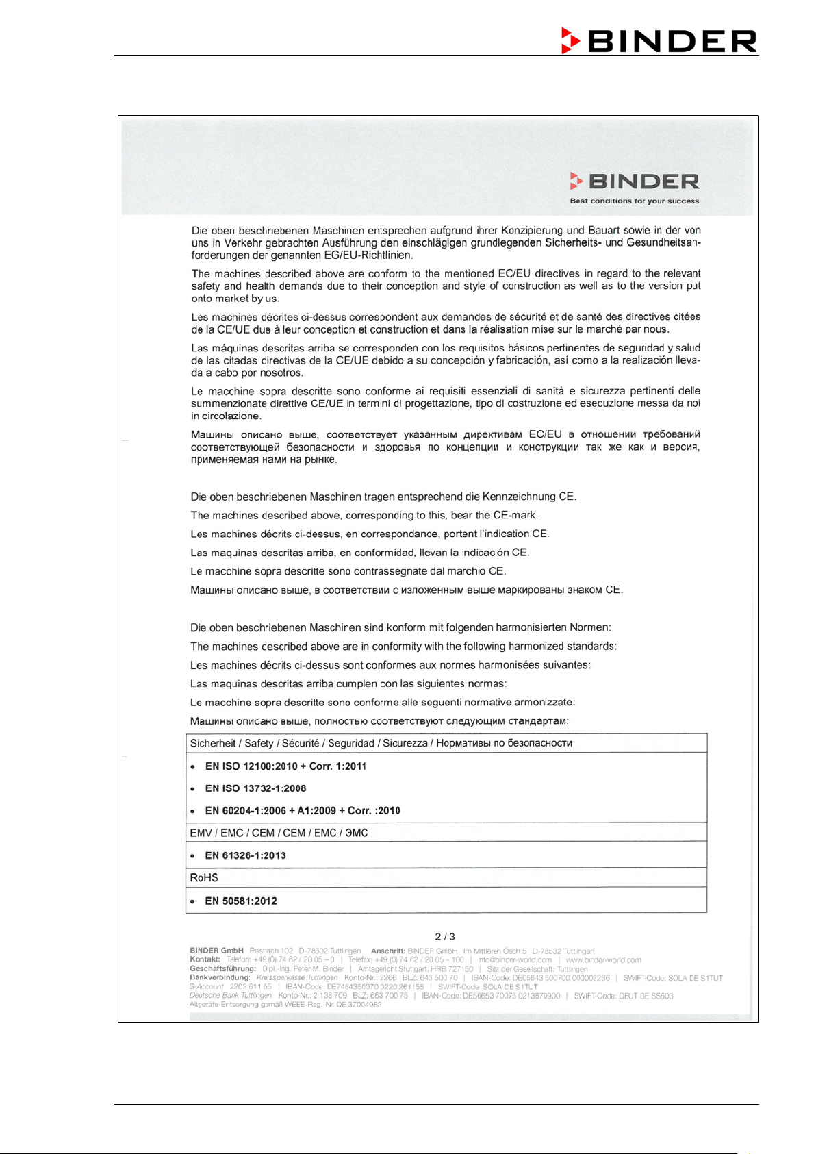
BD / ED / FD (E2) 03/2019 page 58/68
Page 59

BD / ED / FD (E2) 03/2019 page 59/68
Page 60

13.4 Certificate for the GS mark of conformity of the “Deutsche Gesetzliche Unfallversicherung e.V.“ (German Social Accident Insurance) DGUV
BD / ED / FD (E2) 03/2019 page 60/68
Page 61

BD / ED / FD (E2) 03/2019 page 61/68
Page 62

14. P roduct registration
BD / ED / FD (E2) 03/2019 page 62/68
Page 63

•
1. Unit/ component part / type: / Gerät / Bauteil / Typ:
2. Serial No./ Serien-Nr.:
3. Details about utilized substances / biological substances / Einzelheiten über die eingesetzten
3.1 Designations / Bezeichnungen:
3.2 Safety measures required for handling these substances / Vorsichtsmaßnahmen beim
15. Contamination clearance certificate
15.1 For chambers located outside the USA and Canada
Declaration with regard to safety and health
Erklärung zur Sicherheit and gesundheitlichen Unbedenklichkeit
The German Ordinance on Ha zardous Substances (Gef StofV), and the regulations regarding safety at
the workplace, require tha t this f orm be filled out for all products that are retur ned to us, so that the s afet y
and health of our employees can be warranted.
Die Sicherheit und Gesundheit unserer Mitarbeiter, die Gefahrstoffverordnung GefStofV und die Vorschriften zur
Sicherheit am Arbeitsplatz machen es erforderlich, dass dieses Formblatt für alle Produkte, die an uns
zurückgeschickt wird.
In the absence of a completely filled out form, a repair is not possible.
Ohne Vorliegen des vollständig ausgefüllten Formblattes ist eine Reparatur nicht möglich.
A completely filled out f orm should be transm itted by Fax (+49 (0) 7462 2005 93555) or by letter in
advance to us, so t hat this information is available before the equipm ent/component part arrives. A
second copy of this form should accompany the equipment/component part. Eventually the carrier
should be informed.
Eine vollständig ausgefüllte Kopie dieses Formblattes soll per Telefax (Nr. +49 (0) 7462 2005 93555) oder Brief
vorab an uns gesandt werden, so dass die Information vorliegt, bevor das Gerät/Bauteil eintrifft. Eine weitere
Kopie soll dem Gerät/Bauteil beigefügt sein. Ggf. ist auch die Spedition zu informieren.
• Incomplete i nformation or non-c onformity with this pr ocedure will inev itably lead to subst antial delays
in processing. W e hope you will have und erstand ing for this measure, wh ich lies outsid e of our area of
influence, and that you will help us to speed up this procedure.
Unvollständige Angaben oder Nichteinhalten dieses Ablaufs führen zwangsläufig zu beträchtlichen
Verzögerungen in der Abwicklung. Bitte haben Sie Verständnis für Maßnahmen, die außerhalb unserer
Einflussmöglichkeiten liegen und helfen Sie mit, den Ablauf beschleunigen.
• Please fill out this form completely.
Bitte unbedingt vollständig ausfüllen!
Substanzen/biologische Materialien:
a) ____________________________________________________________________________
b) ____________________________________________________________________________
c) ____________________________________________________________________________
Umgang mit diesen Stoffen:
a) ____________________________________________________________________________
b) ____________________________________________________________________________
c) ____________________________________________________________________________
BD / ED / FD (E2) 03/2019 page 63/68
Page 64

3.3 Measures to be taken in case of skin contact or release into the atmosphere / Maßnahmen
3.4 Other important information that must be taken into account / Weitere zu beachtende und
4. Declaration on the risk of these substances (please checkmark the applicable items) /
4.1 For non toxic, non radioactive, biologically harmless materials / für nicht giftige, nicht
Wir versichern, dass o.g.
weder giftige noch
evtl. Rückstände von Gefahrstoffen
4.2 For toxic, radioactive, biologically harmful or hazardous substances, or any other
ch bedenkliche bzw. gefährliche Stoffe oder
die gefährlichen Stoffe, die mit dem o.g. Gerät/Bauteil in Kontakt kamen, in 3.1 aufgelistet
das Gerät/Bauteil nicht mit
5. Kind of transport / transporter / Transportweg/Spediteur:
bei Personenkontakt oder Freisetzung:
a) ____________________________________________________________________________
b) ____________________________________________________________________________
c) ____________________________________________________________________________
d) ____________________________________________________________________________
wichtige Informationen:
a) ____________________________________________________________________________
b) ____________________________________________________________________________
c) ____________________________________________________________________________
Erklärung zur Gefährlichkeit der Stoffe (bitte Zutreffendes ankreuzen) :
radioaktive, biologisch ungefährliche Stoffe:
We herewith guarantee that the above-mentioned unit / comp o n ent part… /
Gerät/Bauteil...
Has not be en exposed t o or cont ains an y toxic or o therwise ha zardous s ubstances /
sonstige gefährliche Stoffe enthält oder solche anha ften.
That eventually generated r eaction products are n on-toxic and also do not represent a hazard /
evtl. entstandene Reaktionsprodukte weder giftig sind noch sonst eine Gefährdung darstellen.
auch
Eventual residues of hazardous substances have been removed /
entfernt wurden.
hazardous materials / für giftige, radioaktive, biologis
anderweitig gefährliche Stoffe.
We herewith guarantee that … /
Wir versichern, dass …
The hazardous substances, which have come into contact with the above-mentioned
equipment/com ponent part, have b een c om pletel y listed under i tem 3.1 and that all i nform ation in this
regard is complete /
sind und alle Angaben vollständig sind.
That the unit /component part has not been in contact with radioactivity /
Radioaktivität in Berührung kam
Transport by (means and name of transport company, etc.) Versendung durch (Name Spediteur o.ä.)
___________________________________________________________________________________
Date of dispatch to BINDER Gm bH / Tag der Absend ung an BIND ER GmbH:
___________________________________________________________________________________
BD / ED / FD (E2) 03/2019 page 64/68
Page 65

We herewith declare that the following measures have been taken / Wir erklären, dass folgende
das Gerät/Bauteil wurde von
Gefahrstoffen befreit, so dass bei Handhabung/Reparaturen für die betreffenden Person keinerlei Gefährdung
ändig
Information about the hazardousness of the shipment (if required) has been provided to the
We herewith comm it ourselves and guarantee that we will indemnify BINDER GmbH for all damages that
BINDER
für jeden Schaden, der durch unvollständige und unrichtige Angaben entsteht, haften und BINDER gegen eventuell
We are aware that, i n ac c o rdanc e with Ar t icle 823 of t he G er man Civil Code (BGB), we a r e direct ly liable
Maßnahmen getroffen wurden:
Hazardous substances were rem oved from the unit / component part, so that no hazard exists for
corresponding persons in the handling or repair of these items /
besteht
The un it was secur ely pack aged and properl y identified /
gekennzeichnet.
das Gerät wurde sicher verpackt und vollst
transporter / der Spediteur wurde (falls vorgeschrieben) über die Gefährlichkeit der Sendung informiert.
are a consequence of incomplete or incorrect information provided by us, and that we will exempt
BINDER GmbH fr om eventual dam age claim s by third part ies./
entstehende Schadenansprüche Dritter freistellen.
Wir versichern, dass wir gegenüber
with regard to third par ties, in this instanc e espec ially the emplo yees of BIND ER Gm bH, who have b een
entrusted with the handli ng / r epair of the u nit / c omponent. /
hier insbesondere mit der Handhabung/Reparatur des Geräts/des Bauteils betraute Mitarbeiter der Firma BINDER gemäß §823 BGB direkt haften
Es ist uns bekannt, dass wir gegenüber Dritten –
Name: _______________________________________________________________________
Position: _______________________________________________________________________
Datum: _______________________________________________________________________
Date /
Signature / Unterschrift: ______________________________________________________________
Company stamp /
Firmenstempel:
Equipment that is returned to the factory for repair must be accompanied by a completely filled
out contamination clearance certificate. For service and maintenance works on site, such a
contamination clearance certificate must be submitted to the service technician before the
start of the works. No repair or maintenance of the equipment is possible, without a properly
filled out contamination clearance certificate.
BD / ED / FD (E2) 03/2019 page 65/68
Page 66

15.2 For chambers located in the USA and Canada
Product Return Authori zation Request
Please complete this f orm and the Custom er Decontam ination Declarat ion (next 2 pages ) and attach the
required pictures. E-mail to: IDL_SalesOrderProcessing_USA@binder-world.com
After we have received and reviewed the complete information we will decide on the issue of a RMA
number. Please be aware that size specifications, voltage specifications as well as performance
specifications are available on the internet at www.binder-world.us at any time.
Take notice of shipping laws and regulations.
Please fill:
Reason for return request Duplicate order
Duplicate shipment
Demo
Power Plug / Voltage 115V / 230 V / 208 V / 240V
Size does not fit space
Transport Damage
Other (specify below)
_____________________
Is there a replacement PO? Yes No
If yes -> PO #
If yes -> Date PO placed
Purchase order number
BINDER model number
BINDER serial number
Date unit was received
Was the unit unboxed? Yes No
Was the unit plugged in? Yes No
Page one completed by sales
Shock watch tripped? (pictures)
Was the unit in operation? Yes No
Pictures of unit attached?
Pictures of Packaging
attached?
Customer Contact Information Distributor Contact Information
Name
Company
Address
Phone
E-mail
BD / ED / FD (E2) 03/2019 page 66/68
Yes No
Yes No
Pictures have to be attached!
Page 67

1. Unit/ component part / type
2. Serial No.
3. List any exposure to hazardous liquids, gasses or substances and radioactive material
3.1 List with MSDS sheets attached where available or needed
3.2 Sa fety measures required for handling the list under 3.1
3.3 Measure s to be taken in case of skin contact or release into th e atmosphere
3.4 Other important information that must be considered
Customer (End User) Dec ont ami na tion Declaration
Health and Hazard Safety declaration
To protect the health of our employees and the safety at the workplace, we require that this form is
completed by the user for all products and parts that are returned to us. (Distributors or Service
Organizations cannot sign this form)
NO RMA number will be issued without a completed form. Products or parts returned to our
NY warehouse without a RMA number will be refused at the dock.
A second copy of the completed form must be attached to the outside of the shipping box.
:
(if there is not enough space available below, please attach a page):
a) ____________________________________________________________________________
b) ____________________________________________________________________________
c) ____________________________________________________________________________
a) ____________________________________________________________________________
b) ____________________________________________________________________________
c) ____________________________________________________________________________
a) ____________________________________________________________________________
b) ____________________________________________________________________________
c) ____________________________________________________________________________
d) ____________________________________________________________________________
:
a) ____________________________________________________________________________
b) ____________________________________________________________________________
c) ____________________________________________________________________________
:
BD / ED / FD (E2) 03/2019 page 67/68
Page 68

4. Declaration of Decontamination
For toxic, radioactive, biologically and chemically harmful or hazardous substances, or any other
I hereby commit and guarantee that we will indemnify BINDER Inc for all damages that are a
hazardous materials.
We hereby guarantee that
4.1 Any hazardous substances, which have come into contact with the above-mentioned equipment /
component part, have been completely listed under item 3.1 and that all information in this regard is
complete
.
4.2 That the unit /component part has not been in contact with radioactivity
4.3 Any Hazardous substances were removed from the unit / component part, so that no hazard exists
for a persons in the shipping, handling or repair of these returned unit
4.4 The unit was securely packaged in the original undamaged packaging and properly identified on the
outside of the packaging material with the unit designation, the RMA number and a copy of this
declaration.
4.5 Shipping laws and regulations have not been violated.
consequence of incomplete or incorrect information provided by us, and that we will indemnify
and hold harmless BINDER Inc. from eventual d amage claims by third parties.
Name: _______________________________________________________________________
Position: _______________________________________________________________________
Company: _______________________________________________________________________
Address: _______________________________________________________________________
Phone #: _______________________________________________________________________
Email: _______________________________________________________________________
Date: _______________________________________________________________________
Signature: _______________________________________________________________________
Equipment returned to the NY warehouse for repair must be accompanied by a completed
customer decontamination declaration. For service and maintenance works on site, such a
customer decontamination declaration must be submitted to the service technician before the
start of work. No repair or maintenance of the equipment is possible without a completed form.
BD / ED / FD (E2) 03/2019 page 68/68
Page 69

 Loading...