

Binder APT.line KT 53, APT.line KT 115, APT.line KT 115-UL, APT.line KT 53-UL Operating Manual
Page 1

Model
Art. No.
KT 53 (E6)
9020-0250, 9120-0250
KT 53-UL (E6)
9020-0255, 9120-0255
KT 115 (E6)
9020-0209, 9120-0209
KT 115-UL (E6)
9020-0227, 9120-0227
Operating Manual
APT.line™ KT (E6)
Refrigerated Incubator
with microprocessor program controller T4.12
and Peltier Refrigerating Technology
BINDER GmbH
Address Post office box 102
D-78502 Tuttlingen
Tel. +49 7462 2005 0
Fax +49 7462 2005 100
Internet http://www.binder-world.com
E-mail info@binder-world.com
Service Hotline +49 7462 2005 555
Service Fax +49 7462 2005 93 555
Service E-Mail service@binder-world.com
Service Hotline USA +1 866 885 9794 or +1 631 224 4340 x3
Service Hotline Asia Pacific +852 39070500 or +852 39070503
Service Hotline Russia and CIS +7 495 98815 17
Issue 09/2013 Art. No. 7001-0241
Page 2

EG – KONFORMITÄTSERKLÄRUNG
Anschrift / Address / Adresse:
Typenbezeichnung / Type / Type:
EG – declaration of conformity
EC - DECLARATION OF CONFORMITY
CE - DECLARATION DE CONFORMITE
Anbieter / Supplier / Fournisseur:
Produkt / Product / Produit:
Die oben beschriebenen Produkte sind konform mit folgenden EG-Richtlinien:
The products described above are in conformity with the following EC guidelines:
Les produits décrits ci-dessus sont conformes aux directives CE suivantes:
Niederspannungsrichtlinie
2006/95/EG
Low voltage directive
2006/95/EC
Directive basse tension
2006/95/CE
EMV-Richtlinie
2004/108/EG
EMC Directive
2004/108/EC
Directive CEM
2004/108/CE
BINDER GmbH
Im Mittleren Ösch 5, D-78532 Tuttlingen
Kühlbrutschränke mit Programmregelung
Refrigerated incubators with program control
Incubateurs réfrigérés à régulation programmable
KT 53, KT 115
Richtlinie 2006/95/EG des Europäischen Parlaments und des
Rates vom 12. Dezember 2006 zur Angleichung der
Rechtsvorschriften der Mitgliedstaaten betreffend elektrische
Betriebsmittel zur Verwendung innerhalb bestimmter
Spannungsgrenzen
Council Directive 2006/95/EC of 12 December 2006 on the
harmonization of the laws of Member States relating to electrical
equipment designed for use within certain voltage limits
Directive 2006/95/CE du Parlement Européen et du Conseil du 12
décembre 2006 concernant le rapprochement des législations des
États membres relatives au matériel électrique destiné à être
employé dans certaines limites de tension
Richtlinie 2004/108/EG des Europäischen Parlaments und des
Rates vom 15. Dezember 2004 zur Angleichung der
Rechtsvorschriften der Mitgliedstaaten über die
elektromagnetische Verträglichkeit und zur Aufhebung der
Richtlinie 89/336/EWG.
Directive 2004/108/EC of the European Parliament and of the
Council of 15 December 2004 on the approximation of the laws of
the Member States relating to electromagnetic compatibility and
repealing Directive 98/336/EEC.
Directive 2004/108/CE du Parlement Européen et du Conseil du
15 décembre 2004 relative au rapprochement des législations des
États membres concernant la compatibilité électromagnétique et
abrogeant le directive 98/336/CEE.
Die oben beschriebenen Produkte tragen entsprechend die Kennzeichnung CE.
The products described above, corresponding to this, bear the CE-mark.
Les produits décrits ci-dessus, en correspondance, portent l’indication CE.
KT (E6) 09/2013 Page 2/135
1 / 3
Page 3

Sicherheit / safety / sécurité:
EMV / EMC / CEM:
Die oben beschriebenen Produkte sind konform mit folgenden harmonisierten Normen:
The products described above are in conformity with the following harmonized standards:
Les produits décrits ci-dessus sont conformes aux normes harmonisées suivantes:
EN 61010-1:2010 Sicherheitsbestimmungen für elektrische Mess-, Steuer-, Regel- und
Laborgeräte – Teil 1: Allgemeine Anforderungen (DIN EN 610101:2011, VDE 411-1:2011)
Safety requirements for electrical equipment for measurement, control,
and laboratory use – Part 1: General requirements (IEC 61010-1:2010,
BS EN 61010-1:2010)
Règles de sécurité pour appareils électriques de mesurage, de
régulation et de laboratoire – Partie 1: Prescriptions générales (CEI
61010-1:2010, NF EN 61010:2011)
EN 61010-2-010:2003 Sicherheitsbestimmungen für elektrische Meß-, Steuer-, Regel- und
Laborgeräte – Teil 2-010: Besondere Anforderungen an Laborgeräte für
das Erhitzen von Stoffen (DIN EN 61010-2-010:2004)
Safety requirements for electrical equipment for measurement, control,
and laboratory use – Part 2-010: Particular requirements for laboratory
equipment for the heating of materials (IEC 61010-2-10:2005, BS EN
61010-2-10:2003)
Règles de sécurité pour appareils électriques de mesurage, de
régulation et de laboratoire – Partie 2-010 : Prescriptions particulières
pour appareils de laboratoire utilisés pour l’échauffement des matières
(CEI 61010-2-10:2003, NF EN 61010-2-10:2005)
EN 61326-1:2006
+ Corr. 1:2008 + Corr. 2:2010
Elektrische Mess-, Steuer-, Regel- und Laborgeräte - EMVAnforderungen - Teil 1: Allgemeine Anforderungen (DIN EN 613261:2006 + Berichtigung 1:2008 + Berichtigung 2:2011)
Electrical equipment for measurement, control and laboratory use EMC requirements - Part 1: General requirements (IEC 61326-1:2005 +
Corr. 1:2008 + Corr. 2:2010, BS EN 61326-1:2006+ A1:2008)
Matériel électrique de mesure, de commande et de laboratoire Exigences relatives à la CEM - Partie 1: Exigences générales (CEI
61326-1:2005 + AC1:2008, NF EN 61326-1:2006 mod.)
EN 61326-2-2:2006 Elektrische Mess-, Steuer-, Regel- und Laborgeräte – EMV-
Anforderungen. Teil 2-2: Besondere Anforderungen - Prüfanordnung,
Betriebsbedingungen und Leistungsmerkmale für ortsveränderliche
Prüf-, Mess- und Überwachungsgeräte in NiederspannungsStromversorgungsnetzen. (DIN EN 61326-2-2:2006)
Electrical equipment for measurement, control and laboratory use –
EMC requirements. Part 2-2: Particular requirements - Test
configurations, operational conditions and performance criteria for
portable test, measuring and monitoring equipment used in low-voltage
distribution systems. (IEC 61326-2-2:2005, BS EN 61326-2-2:2006)
Matériel électrique de mesure, de commande et de laboratoire –
Exigences relatives à la CEM. Partie 2-2: Exigences particulières Configurations d’essai, conditions de fonctionnement et critères
d’aptitude à la fonction des matériels portatifs d’essai, de mesure et de
surveillance utilisés dans des systèmes de distribution basse tension.
(CEI 61326-2-2:2005 + AC1:2007, NF EN 61326-2-2:2006)
KT (E6) 09/2013 Page 3/135
2 / 3
Page 4

P. M. Binder
B. Hofmann
D-78532 Tuttlingen, 20.07.2012
BINDER GmbH
Geschäftsführender Gesellschafter
Managing Director
Directeur général
Leiter F & E
Director R & D
Chef de service R&D
3 / 3
KT (E6) 09/2013 Page 4/135
Page 5
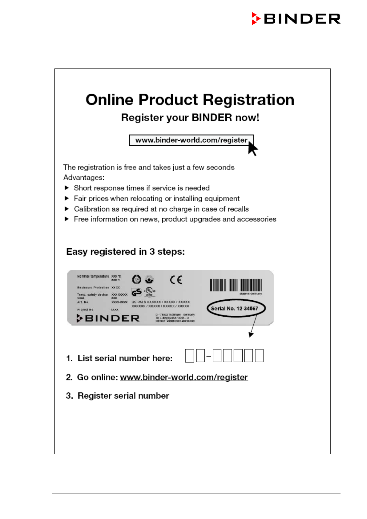
Product registration
KT (E6) 09/2013 Page 5/135
Page 6

Contents
EG – declaration of conformity ...................................................................................................................... 2
Product registration ....................................................................................................................................... 5
1. SAFETY ................................................................................................................ 10
1.1 Legal considerations ......................................................................................................................... 10
1.2 Structure of the safety instructions .................................................................................................... 10
1.2.1 Signal word panel ................................................................................................................... 10
1.2.2 Safety alert symbol ................................................................................................................. 11
1.2.3 Pictograms .............................................................................................................................. 11
1.2.4 Word message panel structure ............................................................................................... 12
1.3 Localization / position of safety labels on the unit ............................................................................. 12
1.4 Type plate ......................................................................................................................................... 13
1.5 General safety instructions on installing and operating the refrigerated incubator ........................... 14
1.6 Intended use ..................................................................................................................................... 15
2. UNIT DESCRIPTION ............................................................................................ 16
2.1 Unit overview ..................................................................................................................................... 17
2.2 Instrument panel ............................................................................................................................... 17
2.3 Unit rear............................................................................................................................................. 18
3. COMPLETENESS OF DELIVERY, TRANSPORTATION, STORAGE, AND
LOCATION OF INSTALLATION .......................................................................... 19
3.1 Unpacking, and checking equipment and completeness of delivery ................................................ 19
3.2 Guidelines for safe lifting and transportation..................................................................................... 19
3.3 Storage .............................................................................................................................................. 20
3.4 Location of installation and ambient conditions ................................................................................ 20
4. INSTALLATION OF THE EQUIPMENT ............................................................... 21
4.1 Spacer for wall distance .................................................................................................................... 21
4.2 Electrical connection ......................................................................................................................... 22
5. START UP ............................................................................................................ 23
6. FUNCTIONAL OVERVIEW OF THE T4.12 CHAMBER CONTROLLER ............. 23
6.1 Menu structure .................................................................................................................................. 24
6.1.1 General menu ......................................................................................................................... 24
6.1.2 Quick menu ............................................................................................................................. 26
6.1.3 “User” menu ............................................................................................................................ 26
6.2 Operating modes ............................................................................................................................... 27
6.2.1 Activating the “control off” mode or change to “fixed value” operating mode ......................... 27
6.3 Performance during and after power failure ...................................................................................... 29
6.4 Information ........................................................................................................................................ 30
7. CONFIGURATION OF OPTIONAL EQUIPMENT ................................................ 31
7.1 Setting the optional door heating ...................................................................................................... 31
7.2 Turning on / off the optional interior socket ....................................................................................... 32
7.3 Switching on or off the optional zero-voltage relay control outputs .................................................. 32
7.4 Functional test of the optional alarm output ...................................................................................... 33
7.5 Switching on or off the optional object temperature display ............................................................. 33
8. SET-POINT ENTRY IN “FIXED VALUE” OPERATING MODE ........................... 34
8.1 Setting ranges: .................................................................................................................................. 34
8.2 Entering the set-points via “quick menu” ........................................................................................... 34
8.3 Entering the set-points via general menu ......................................................................................... 36
KT (E6) 09/2013 Page 6/135
Page 7

9. TIME PROGRAMS ............................................................................................... 38
9.1 Starting and running an existing time program ................................................................................. 40
9.2 Cancelling a running time program ................................................................................................... 43
9.3 Creating a new time program ............................................................................................................ 44
9.3.1 Section handling ..................................................................................................................... 46
9.3.2 Temperature setpoint .............................................................................................................. 47
9.3.3 Section duration ...................................................................................................................... 47
9.3.4 Repeating one or several sections within a time program ...................................................... 48
9.3.5 Tolerance range ...................................................................................................................... 49
9.3.6 Set-point ramp and set-point step modes ............................................................................... 51
9.3.7 Switching on or off the optional zero-voltage relay outputs .................................................... 53
9.3.8 Calling up the next parameter ................................................................................................. 54
9.3.9 Saving the time program and leaving the program editor ....................................................... 56
9.4 Program interruption ......................................................................................................................... 58
9.5 Deleting a time program .................................................................................................................... 59
10. WEEK PROGRAMS ............................................................................................. 60
10.1 Starting and running an existing week program ............................................................................... 61
10.2 Cancelling a running week program ................................................................................................. 64
10.3 Creating a new week program .......................................................................................................... 65
10.3.1 Section handling ..................................................................................................................... 67
10.3.2 Temperature setpoint .............................................................................................................. 68
10.3.3 Day of the week ...................................................................................................................... 68
10.3.4 Time of the day ....................................................................................................................... 69
10.3.5 Activity of the shift-point .......................................................................................................... 70
10.3.6 Switching on or off the optional zero-voltage relay outputs .................................................... 70
10.3.7 Calling up the next parameter ................................................................................................. 71
10.3.8 Saving the week program and leaving the program editor ..................................................... 73
10.4 Deleting a week program .................................................................................................................. 74
11. KEY LOCK ........................................................................................................... 75
11.1 Directly activating the key lock function ............................................................................................ 76
11.2 Automatic key lock ............................................................................................................................ 76
11.3 Changing the password for unlocking the key lock ........................................................................... 78
12. GENERAL CONTROLLER SETTINGS ................................................................ 79
12.1 Setup wizard ..................................................................................................................................... 80
12.2 Date and time settings ...................................................................................................................... 80
12.3 Selecting the menu language of the T4.12 controller ....................................................................... 82
12.4 Setting display brightness ................................................................................................................. 82
12.5 Changing the temperature unit ......................................................................................................... 83
12.6 Defining the data recording rate ........................................................................................................ 83
12.7 Factory reset ..................................................................................................................................... 84
12.8 Network configuration ....................................................................................................................... 84
12.9 Display of the entire network configuration ....................................................................................... 88
12.10 MAC Address .................................................................................................................................... 88
12.11 RS 422 address (with optional RS 422 interface) ............................................................................. 89
12.12 Display and entry of the chamber configuration – for service purpose ............................................. 89
13. DATA TRANSFER VIA USB INTERFACE .......................................................... 90
13.1 Exporting data to USB drive .............................................................................................................. 90
13.2 Importing data from USB drive .......................................................................................................... 91
14. NOTIFICATIONS AND ALARMS ......................................................................... 92
14.1 Notifications overview ....................................................................................................................... 92
14.2 Alarms overview ................................................................................................................................ 92
14.3 Confirming an active alarm ............................................................................................................... 93
KT (E6) 09/2013 Page 7/135
Page 8

14.4
Alarm configuration and overview ..................................................................................................... 94
14.4.1 List of active alarms ................................................................................................................ 95
14.4.2 History – list of all alarms ........................................................................................................ 95
14.4.3 Activating, deactivating, and testing the alarm buzzer ........................................................... 96
14.4.4 Activating / deactivating all alarm functions ............................................................................ 97
15. EVENT LIST ......................................................................................................... 98
16. GRAPHICAL DISPLAY OF THE MEASURED VALUES ..................................... 99
16.1 Setting the sampling rate .................................................................................................................. 99
16.2 Defining the display range............................................................................................................... 100
16.3 Selecting the parameters ................................................................................................................ 101
17. TEMPERATURE SAFETY DEVICES ................................................................. 102
17.1 Overtemperature protective device (class 1) .................................................................................. 102
17.2 Overtemperature safety controller (temperature safety device class 3.1) ...................................... 102
17.2.1 Safety controller modes ........................................................................................................ 102
17.2.2 Setting the safety controller .................................................................................................. 103
17.3 Over- and undertemperature safety controller (temperature safety device class 3.3) (option) ...... 106
17.3.1 Safety controller modes ........................................................................................................ 106
17.3.2 Setting the Safety controller .................................................................................................. 107
18. NOTES ON REFRIGERATING OPERATION .................................................... 110
19. OPTIONS ............................................................................................................ 110
19.1 Communication software APT-COM™ 3 DataControlSystem (option)........................................... 110
19.2 RS 422 interface (option) ................................................................................................................ 110
19.3 Data logger kit (option) .................................................................................................................... 111
19.4 Object temperature display with flexible Pt 100 temperature sensor (option) ................................ 111
19.5 Zero-voltage relay alarm output (option) ......................................................................................... 112
19.6 Analog output for temperature (option) ........................................................................................... 113
19.7 Zero-voltage relay control outputs (option) ..................................................................................... 113
19.8 Water protected internal socket (option) ......................................................................................... 114
20. MAINTENANCE, CLEANING, AND SERVICE .................................................. 115
20.1 Maintenance intervals, service ........................................................................................................ 115
20.2 Cleaning and decontamination ....................................................................................................... 116
20.2.1 Cleaning ................................................................................................................................ 116
20.2.2 Decontamination ................................................................................................................... 117
20.3 Sending the unit back to BINDER GmbH ....................................................................................... 118
21. DISPOSAL ......................................................................................................... 119
21.1 Disposal of the transport packing .................................................................................................... 119
21.2 Decommissioning ............................................................................................................................ 119
21.3 Disposal of the unit in the Federal Republic of Germany ............................................................... 119
21.4 Disposal of the unit in the member states of the EC except for the Federal Republic of Germany 120
21.5 Disposal of the unit in non-member states of the EC ..................................................................... 121
22. TROUBLESHOOTING ....................................................................................... 122
23. TECHNICAL DESCRIPTION .............................................................................. 124
23.1 Factory calibration and adjustment ................................................................................................. 124
23.2 Over current protection ................................................................................................................... 124
23.3 Definition of usable volume ............................................................................................................. 124
23.4 KT technical data ............................................................................................................................ 125
23.5 Equipment and Options ................................................................................................................... 126
23.6 Spare parts and accessories .......................................................................................................... 127
23.7 Dimensions KT 53 ........................................................................................................................... 128
23.8 Dimensions KT 115 ......................................................................................................................... 129
KT (E6) 09/2013 Page 8/135
Page 9

24. CONTAMINATION CLEARANCE CERTIFICATE ............................................. 130
24.1 For units located outside North America and Central America ....................................................... 130
24.2 For units in North America and Central America ............................................................................ 133
KT (E6) 09/2013 Page 9/135
Page 10
Dear customer,
For the correct operation of the refrigerated incubator KT, it is important that you read this operating
manual completely and carefully and observe all instructions as indicated. Failure to read, understand
and follow the instructions may result in personal injury. It can also lead to damage to the unit and/or poor
equipment performance
1. Safety
This operating manual is part of the components of delivery. Always keep it handy for reference. The
device should only be operated by laboratory personnel especially trained for this purpose and familiar
with all precautionary measures required for working in a laboratory. To avoid injuries and damage
observe the safety instructions of the operating manual.
WARNING
Failure to observe the safety instructions.
Serious injuries and unit damage.
Observe the safety instructions in this operating manual.
Carefully read the complete operating instructions of the refrigerated incubator KT.
1.1 Legal considerations
This operating manual is for informational purposes only. It contains information for installing, start-up,
operation and maintenance of the product. Note: the contents and the product described are subject to
change without notice.
Understanding and observing the instructions in this operating manual are prerequisites for hazard-free
use and safety during operation and maintenance. In no event shall BINDER be held liable for any
damages, direct or incidental arising out of or related to the use of this manual.
This operating manual cannot cover all conceivable applications. If you would like additional information,
or if special problems arise that are not sufficiently addressed in this manual, please ask your dealer or
contact us directly by phone at the number located on page one of this manual
Furthermore, we emphasize that the contents of this operating manual are not part of an earlier or
existing agreement, description, or legal relationship, nor do they modify such a relationship. All
obligations on the part of BINDER derive from the respective purchase contract, which also contains the
entire and exclusively valid statement of warranty administration. The statements in this manual neither
augment nor restrict the contractual warranty provisions.
1.2 Structure of the safety instructions
In this operating manual, the following safety definitions and symbols indicate dangerous situations
following the harmonization of ISO 3864-2 and ANSI Z535.6.
1.2.1 Signal word panel
Depending on the probability of serious consequences, potential dangers are identified with a signal
word, the corresponding safety color, and if appropriate, the safety alert symbol.
DANGER
Indicates an imminently hazardous situation that, if not avoided, will result in death or serious
(irreversible) injury.
KT (E6) 09/2013 Page 10/135
Page 11
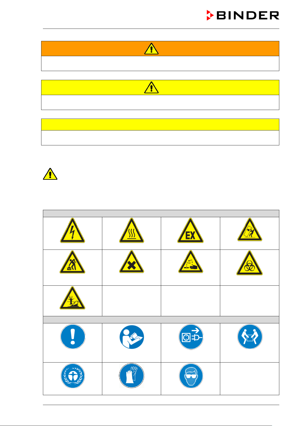
Warning signs
Electrical hazard
Hot surface
Explosive atmosphere
or chemical burns
Pollution Hazard
Mandatory action signs
plug
Environment protection
Wear protective gloves
Wear safety goggles
WARNING
Indicates a potentially hazardous situation which, if not avoided, could result in death or serious
(irreversible) injury.
CAUTION
Indicates a potentially hazardous situation which, if not avoided, may result in moderate or minor
(reversible) injury.
CAUTION
Indicates a potentially hazardous situation which, if not avoided, may result in damage to the product
and/or its functions or of a property in its proximity.
1.2.2 Safety alert symbol
Use of the safety alert symbol indicates a risk of injury.
Observe all measures that are marked with the safety alert symbol in order to avoid death or
injury.
1.2.3 Pictograms
Lifting hazard
Harmful substances
Risk of corrosion and /
Stability hazard
Biohazard
Mandatory regulation
KT (E6) 09/2013 Page 11/135
Read operating
instructions
Disconnect the power
Lift with several persons
Page 12
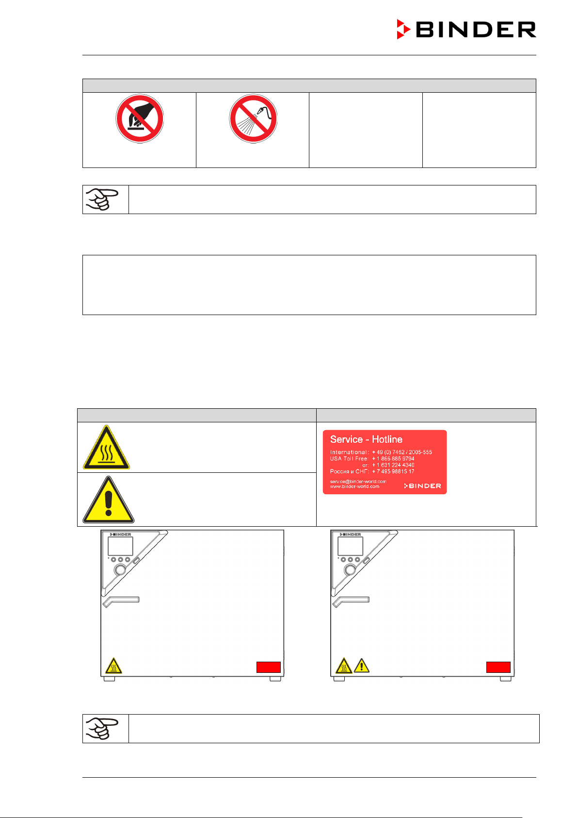
Prohibition signs
water
Pictograms (Warning signs)
Service label
Unit front KT
Unit front KT-UL
Do NOT touch
Do NOT spray with
Information to be observed in order to ensure optimum function of the product.
1.2.4 Word message panel structure
Type / cause of hazard.
Possible consequences.
Instruction how to avoid the hazard: prohibition
Instruction how to avoid the hazard: mandatory action
Observe all other notes and information not necessarily emphasized in the same way, in order to avoid
disruptions that could result in direct or indirect injury or property damage.
1.3 Localization / position of safety labels on the unit
The following labels are located on the unit:
Hot surface
Risk of injury (UL units only)
Figure 1: Position of labels on the unit
Replace safety labels that are no longer legible. Contact BINDER service for these replacements.
KT (E6) 09/2013 Page 12/135
Keep safety labels complete and legible.
Page 13
Indications of the type plate
Information
BINDER
Manufacturer: BINDER GmbH
KT 115
Model KT 115
Serial No.
00-00000
Serial No. 00-00000
Nominal temperature
100 °C
212 °F
Enclosure protection
IP 20
IP type of protection 20 acc. to EN 60529
Temp. safety device
DIN 12880
Temperature safety device acc. to standard DIN 12880
Class
3.1
Temperature safety device, class 3.1
Art. No.
9020-0209
Art. No. 9020-0209
Project No.
---
(Special application acc. to project no.)
0.70 kW
Nominal power 0.70 kW
200-240 V 1 N ~
Nominal voltage 200-240 V ± 10%, single-phase unit
3.0 A
Nominal current 3.0 Amp
50/60 Hz
Power frequency 50/60 Hz
Thermoelectric cooling Peltier
Peltier refrigerating technology
Symbol on the type plate
Information
LABORATORY EQUIPMENT
43KM
Nominal temperature
100°C
0,70 kW
Thermoelectric cooling
212°F
200-240 V 1 N ~
Peltier
Temp. safety device
IP 20
DIN 12880
50/60 Hz
3.1
Art. No.
9020-0209
US PATS 4585923 / 5222612 / 5309981
D 78532 Tuttlingen / Germany
Internet: www.binder-world.com
1.4 Type plate
The type plate is located on the left unit side, on the bottom, right side.
Enclosure protection
Class
Project No.
3,0 A
5405194 / 5601143 / 5773287 / 6079403
Tel. + 49 (0) 7462/ 2005-0
Figure 2: Type plate (example of KT 115 regular unit)
Nominal temperature
KT 115 Serial No. 00-00000
Made in Germany
CE conformity marking
Electrical and electronic equipment manufactured / placed on
the market in the EC after 13 August 2005 and to be disposed of
in separate collection according to directive 2002/96/EC on
waste electrical and electronic equipment (WEEE).
The equipment is certified in the GOST R certification system of
GOSTSTANDARD Russia.
The equipment is certified by Underwriters Laboratories Inc.®
according to standards CAN/CSA-C22.2 No. 61010-1, 2
nd
Edition, 2004-07 (Electrical Equipment for Measurement,
(KT-UL only)
Control, and Laboratory Use; Part 1: General Requirements); UL
61010-1, 2
Measurement, Control, and Laboratory Use; Part 1: General
Requirements); IEC 61010-1:2010, 3
nd
Edition, 2005-07-22 (Electrical Equipment for
rd
Edition and IEC 61010-210:2003 (Particular Requirements for Laboratory Equipment for
the heating of materials).
KT (E6) 09/2013 Page 13/135
Page 14
Do NOT introduce any substance into the refrigerated incubator which is combustible or
1.5 General safety instructions on installing and operating the refrigerated incubator
With regard to operating the refrigerated incubator KT and to the installation location, please observe the
guideline BGI/GUV-I 850-0 on safe working in laboratories (formerly BGR/GUV-R 120 or ZH 1/119
laboratory guidelines issued by the employers’ liability insurance association) (for Germany).
BINDER GmbH is only responsible for the safety features of the unit provided skilled electricians or
qualified personnel authorized by BINDER perform all maintenance and repair, and if components
relating to chamber safety are replaced in the event of failure with original spare parts.
To operate the unit, use only original BINDER accessories or accessories from third-party suppliers
authorized by BINDER. The user is responsible for any risk caused by using unauthorized accessories.
CAUTION
Danger of overheating.
Damage to the unit.
∅ Do NOT install the unit in unventilated recesses.
Ensure sufficient ventilation for dispersal of the heat.
Do not operate the refrigerated incubator KT in hazardous locations.
DANGER
Explosion hazard.
Danger of death.
∅ Do NOT operate the unit in potentially explosive areas.
KEEP explosive dust or air-solvent mixtures AWAY from the unit.
The refrigerated incubator KT does not dispose of any measures of explosion protection.
DANGER
Explosion hazard.
Danger of death.
∅
explosive at working temperature.
∅ NO explosive dust or air-solvent mixture in the inner chamber.
Any solvent contained in the charging material must not be explosive or inflammable. I.e., irrespective of
the solvent concentration in the steam room, NO explosive mixture with air must form. The temperature
inside the chamber must lie below the flash point or below the sublimation point of the charging material.
Familiarize yourself with the physical and chemical properties of the charging material, as well as the
contained moisture constituent and its behavior with the addition of heat energy.
Familiarize yourself with any potential health risks caused by the charging material, the contained
moisture constituent or by reaction products which may arise during the temperature process. Take
adequate measures to exclude such risks prior to putting the refrigerated incubator into operation.
DANGER
Electrical hazard.
Danger of death.
∅ The unit must NOT become wet during operation or maintenance.
The refrigerated incubators were produced in accordance with VDE regulations and were routinely tested
in accordance to VDE 0411-1 (IEC 61010-1).
KT (E6) 09/2013 Page 14/135
Page 15
CAUTION
The glass door and the inner chamber will become hot during operation.
Danger of burning.
∅ Do NOT touch the glass door, the inner surfaces or the charging material during
operation.
1.6 Intended use
Refrigerated incubators KT are suitable for exact conditioning of harmless materials. Because of their
precise temperature accuracy these devices are especially useful for cultivation of microorganisms with a
narrow temperature optimum in a range of 4 °C / 39.2°F to 37 °C / 98.6°F. Main fields of application are
tests of long-term storage (e.g. at 4 °C / 39.2°F), refrigerated incubation between 20 °C / 68°F and 25 °C /
77°F and incubation at 37 °C / 98.6°F (also with additional introduction of heat) or with alternating
temperatures (e.g. 37 °C / 98.6°F and 4 °C / 39.2°F).
A mixture of any component of the charging material with air must NOT be explosive. The operating
temperature must lie below the flash point or below the sublimation point of the charging material.
Following the instructions in this operating manual and conducting regular maintenance work
(chap. 20.1) are part of the intended use.
The charging material shall not contain any corrosive ingredients that may damage the
machine components made of stainless steel, aluminum, and copper. Such ingredients
include in particular acids and halides. Any corrosive damage caused by such ingredients is
excluded from liability by BINDER GmbH.
WARNING: If customer should use a BINDER chamber running in non-supervised
continuous operation, we strongly recommend in case of inclusion of irrecoverable specimen
or samples to split such specimen or samples and store them in at least two chambers, if this
is feasible.
KT (E6) 09/2013 Page 15/135
Page 16

2. Unit description
A high level of precision, reliability, and safety for all growth parameters ensures optimum incubation
conditions. Moreover, the KT refrigerated incubator is designed for maximum usability – even in
continuous operation year after year. It fulfills all technical and application-specific requirements arising in
experimentation such as in the areas of biotechnology, medicine, the nutrition industry, pharmaceutical
and cosmetics industries, botany, and zoology.
Two important temperature technologies have been combined to achieve perfect temperature control.
The Peltier refrigerating system, in conjunction with the APT.line™ preheating chamber technology,
satisfies the unique prerequisites for attaining highly-precise temperature control and particularly short
recovery times after opening the door.
The refrigerating system is distinguished by direct, precise, and rapid temperature conduction. Due to the
Peltier cooling, shocks are omitted which would occur during start and stop of conventional refrigeration
systems with a compressor.
The APT.line™ preheating chamber system ensures high level of spatial and time-based temperature
precision, thanks to the direct and distributed air circulation into the interior. This is especially important
for maintaining temperatures – especially with full chambers – and for rapid restoration of optimum growth
conditions after opening the door. The inner glass door ensures that the temperature remains constant
when observing the incubation process. The air turbine supports exact attainment and maintenance of the
desired temperature accuracy. The fan speed is digitally adjustable. The heating and refrigerating
systems are microprocessor regulated to a tenth of a degree. In addition, the refrigerated incubator
provides almost unlimited possibilities for adaptation to individual customer requirements based upon
extensive programming options and on the week program timer and real time clock of the controller.
All unit functions are easy and comfortable to use thanks to their clear arrangement. Major features are
easy cleaning of all unit parts and avoidance of undesired contamination.
The inner chamber, the pre-heating chamber and the interior side of the doors are all made of stainless
steel (material no. 1.4301 (V2A) in Germany, US equivalent 304). The housing is RAL 7035 powdercoated. All corners and edges are also completely coated.
The refrigerated incubator KT comes equipped with an Ethernet interface for computer communication,
e.g. via the communication software APT-COM™ 3 DataControlSystem (option, chap. 19.1). For further
options, see chap. 23.5.
Temperature range with an ambient temperature of 25 °C / 77 °F: +4 °C / 23 °F up to +100 °C / 212 °F
KT (E6) 09/2013 Page 16/135
Page 17
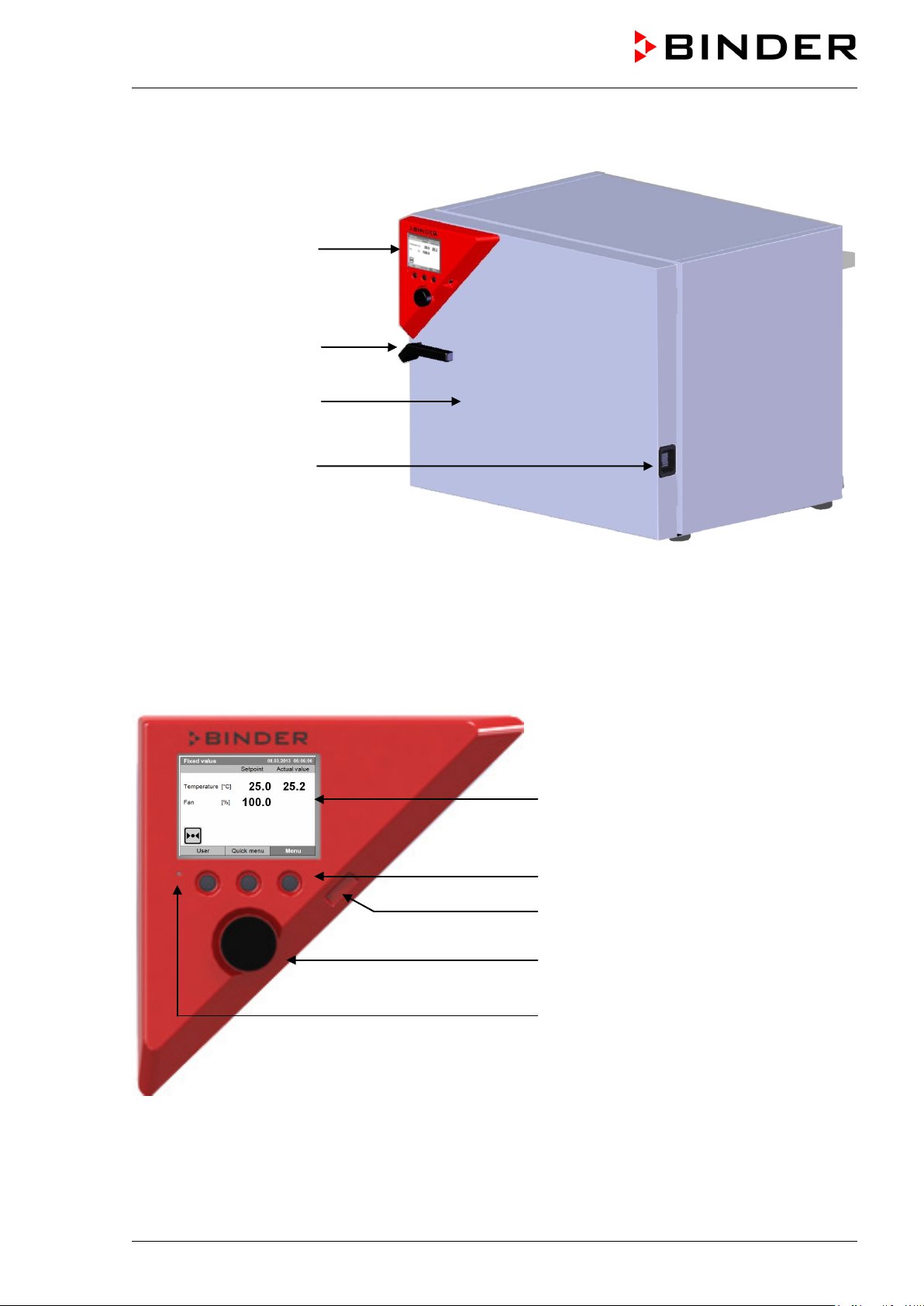
2.1 Unit overview
Instrument panel with
microprocessor controller
T4.12 and USB interface
Door handle
Unit door
Main power switch
Figure 3: Refrigerated incubator KT (example: model KT 115)
2.2 Instrument panel
5,7" controller display
Context-sensitive buttons
USB interface
Operating button
Pilot lamp: ready for operation
Figure 4: Instrument panel with microprocessor controller T4.12 and USB interface
KT (E6) 09/2013 Page 17/135
Page 18
(7) (8)
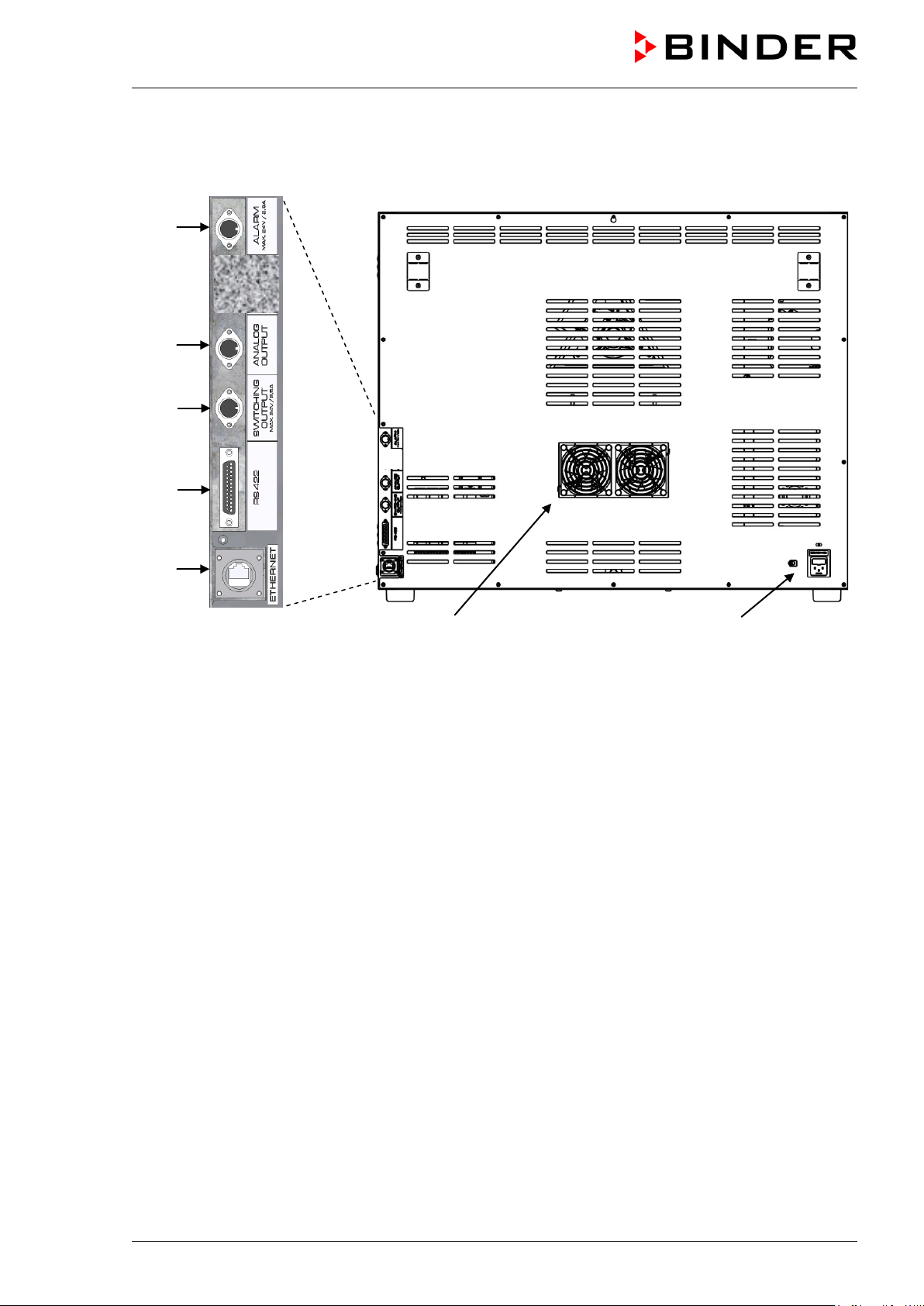
2.3 Unit rear
(1)
(3)
(4)
(5)
(6)
Figure 5: Unit rear with position of options (example KT 115)
(1) DIN-socket for zero-voltage relay alarm outputs (option)
(2) (not used)
(3) DIN socket for analog output 4-20 mA (option)
(4) DIN-socket for zero-voltage relay control outputs (option)
(5) RS 422 interface for computer communication (option)
(6) Ethernet interface for computer communication with MAC address (standard equipment, not with
optional RS 422 interface)
(7) Peltier fan grid
(8) Socket for IEC connector plug with power cable
KT (E6) 09/2013 Page 18/135
Page 19
3. Completeness of delivery, transportation, storage, and location
of installation
3.1 Unpacking, and checking equipment and completeness of delivery
After unpacking, please check the unit and its optional accessories, if any, based on the delivery receipt
for completeness and for transportation damage. Inform the carrier immediately if transportation damage
has occurred.
The final tests of the manufacturer may have caused traces of the shelves on the inner surfaces. This has
no impact on the function and performance of the unit.
Please remove any transportation protection devices and adhesives in/on the unit and on the doors and
remove the operating manuals and accessory equipment.
CAUTION
Sliding or tilting of the unit.
Damage to the unit.
Risk of injury by lifting heavy loads.
Do NOT lift or transport the unit using the door or the door handle.
Lift the unit from the pallet at the four lower corners with the aid of four people.
If you need to return the unit, please use the original packing and observe the guidelines for safe lifting
and transportation (chap. 3.2).
For disposal of the transport packing, see chap. 21.1.
Note on second-hand units (Ex-Demo-Units):
Second-hand units are units that were used for a short time for tests or exhibitions. They are thoroughly
tested before resale. BINDER ensures that the chamber is technically sound and will work flawlessly.
Second-hand units are marked with a sticker on the unit door. Please remove the sticker before
commissioning the unit.
3.2 Guidelines for safe lifting and transportation
After operation, please observe the guidelines for temporary decommissioning (chap. 21.2).
CAUTION
Sliding or tilting of the unit.
Damage to the unit.
Risk of injury by lifting heavy loads.
Transport the unit in its original packaging only.
For moving or shipping, secure the unit with transport straps.
∅ Do NOT lift or transport the unit using the door or the door handle.
Lift the unit at the four lower corners with the aid of 4 people and place it on a rolling
pallet.
KT (E6) 09/2013 Page 19/135
Page 20
Permissible ambient temperature range during transport: 10 °C / 14°F to +60 °C / 140°F.
You can order transport packing for moving or shipping purposes from BINDER service.
3.3 Storage
Intermediate storage of the unit is possible in a closed and dry room. Observe the guidelines for
temporary decommissioning (chap. 21.2).
• Permissible ambient temperature range during storage: -10 °C / 14°F to +60 °C / 140°F.
• Permissible ambient humidity: max. 70 % r.H., non-condensing
When after storage in a cold location you transfer the unit to its warmer installation site, condensation
may form. Before start-up, wait at least one hour until the chamber has attained ambient temperature and
is completely dry.
3.4 Location of installation and ambient conditions
Set up the refrigerated incubator KT on a flat, even surface, free from vibration, in a well-ventilated, dry
location and align it using a spirit level. The site of installation must be capable of supporting the unit’s
weight (see technical data, chap. 23.4). The chambers are designed for setting up inside a building
(indoor use).
CAUTION
Danger of overheating.
Damage to the unit.
Do NOT set up units in non-ventilated recesses.
Ensure sufficient ventilation for dispersal of the heat.
• Permissible ambient temperature range during operation: +18 °C / 64.4°F to +25 °C / 77 °F. At
elevated ambient temperature values, fluctuations in temperature can occur.
The ambient temperature should not be substantially higher than the indicated ambient
temperature of +25 °C / 77°F to which the specified technical data relates. Deviations from the
indicated data are possible for other ambient conditions.
With each degree of ambient temperature > +25 °C / 77°F, the refrigeration power decreases
by 1.5 K.
• Permissible ambient humidity: 70 % r.H. max., non-condensing.
When operating the chamber at temperature set-points below ambient temperature, high ambient
humidity may lead to condensation on the unit.
• Installation height: max. 2000 m / 6.6 ft. above sea level.
When placing several units of the same size side by side, maintain a minimum distance of 250 mm / 9.84
in between each unit. Wall distances (minimum distances): rear 100 mm / 3.94 in, sides 240 mm / 9.45 in.
Spacing above the unit of at least 100 mm / 3.94 in must also be maintained
Two devices up to size 115l can be piled on top of each other. For this purpose, place rubber pads under
all four feet of the upper unit to prevent the device from slipping.
CAUTION
Sliding or tilting of the upper unit.
Damage to the units.
When stacking, place rubber pads under all four feet of the upper unit.
KT (E6) 09/2013 Page 20/135
Page 21
To completely separate the unit from the power supply, you must disconnect the power plug. Install the
unit in a way that the power plug is easily accessible and can be easily pulled in case of danger.
With an increased amount of dust in the ambient air, clean the Peltier fan grid (7) by suction or blowing
several times a year.
Avoid any conductive dust in the ambiance according to the unit layout complying with pollution degree 2
(IEC 61010-1).
Do not install or operate the unit in potentially explosive areas.
DANGER
Explosion hazard.
Danger of death.
∅ Do NOT operate the unit in potentially explosive areas.
KEEP explosive dust or air-solvent mixtures AWAY from the vicinity of the unit.
4. Installation of the equipment
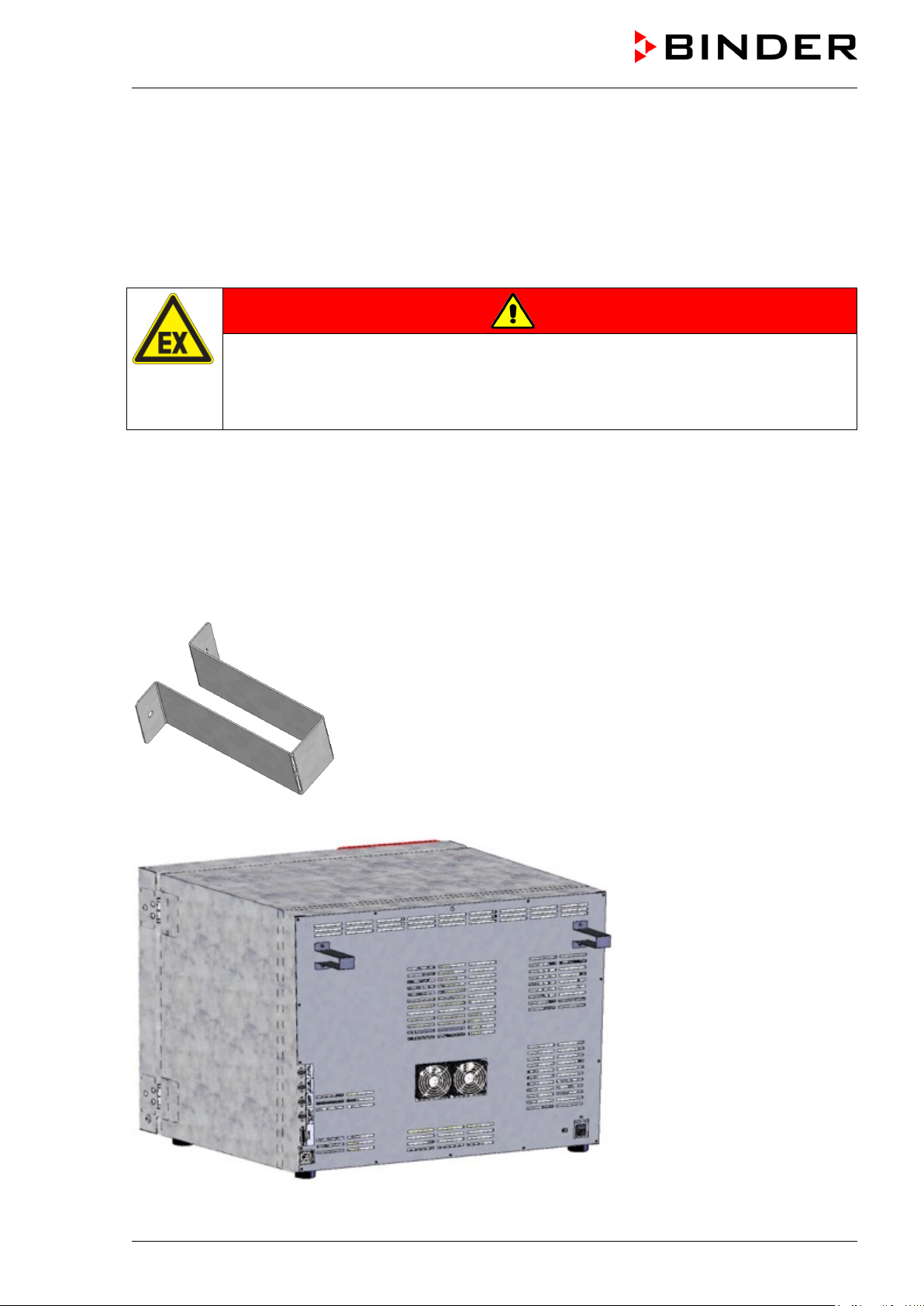
4.1 Spacer for wall distance
Please fix both spacers with the supplied screws at the unit rear. This serves to ensure the prescribed
minimum distance to the rear wall of 100 mm / 3.94 in.
Figure 6: Spacer for wall distance
Figure 7: Rear KT with mounted spacers
KT (E6) 09/2013 Page 21/135
Page 22
KT 115
9x20-0209
plug
KT 53-UL
KT 115-UL
9x20-0255
9x20-0227
4.2 Electrical connection
The refrigerated incubator comes with an IEC connector plug.
Model
KT 53
• Prior to connection and start-up, check the power supply voltage. Compare the values to the specified
data located on the unit’s type plate (left unit side, bottom right-hand, see chap. 1.4).
• When connecting, please observe the regulations specified by the local electricity supply company as
well as the VDE directives (for Germany).
• Pollution degree (acc. to IEC 61010-1): 2
• Over-voltage category (acc. to IEC 61010-1): II
Art. no.
(x = 0 or 1)
9x20-0250
Power plug
Shock-proof
NEMA 5-15P 100 V to 120 V 1N~ 50/60 Hz 10 A
Voltage
+/-10 %
200 V to 240 V 1N~ 50/60 Hz 10 A
Current
type
Power
frequency
Unit fuse
CAUTION
Danger of incorrect power supply voltage.
Damage to the equipment.
Check the power supply voltage before connection and start-up.
Compare the power supply voltage with the data indicated on the type plate.
See also electrical data (chap. 23.4).
To completely separate the unit from the power supply, you must disconnect the power plug.
Install the unit in a way that the power plug is easily accessible and can be easily pulled in
case of danger.
KT (E6) 09/2013 Page 22/135
Page 23
5. Start up
After connecting the electrical supply (chap. 4.2) turn on the chamber by the main power switch. The pilot
lamp shows the unit is ready for operation.
Observe a delay time of about 30s between turning Off and On again. Otherwise an
initialization problem may occur.
Note that the chamber is in stand-by mode when the main power switch has been turned on and yet the
controller display is dark. Turn on the unit by pressing any controller button.
Warming chambers may release odors in the first few days after commissioning. This is not a quality
defect. To reduce odors quickly we recommend heating up the chamber to its nominal temperature for
one day and in a well-ventilated location.
WARNING: If customer should use a BINDER chamber running in non-supervised
continuous operation, we strongly recommend in case of inclusion of irrecoverable specimen
or samples to split such specimen or samples and store them in at least two chambers, if this
is feasible.
6. Functional overview of the T4.12 chamber controller
The T4.12 chamber controller controls the temperature (range: 4 °C up to 100 °C) and the fan speed
(range: 40 % up to 100 %) inside the refrigerated incubator. You can enter the desired set point values in
fixed value operating mode or in program mode in the display controller. The controller also offers a week
program function and various notifications and alarm messages with visual and audible indication, a trace
file and remote alarms via e-mail. You can enter values or programs directly at the controller keypad or
using the APT-COM™ 3 DataControlSystem software (option, chap. 19.1) specially developed by
BINDER.
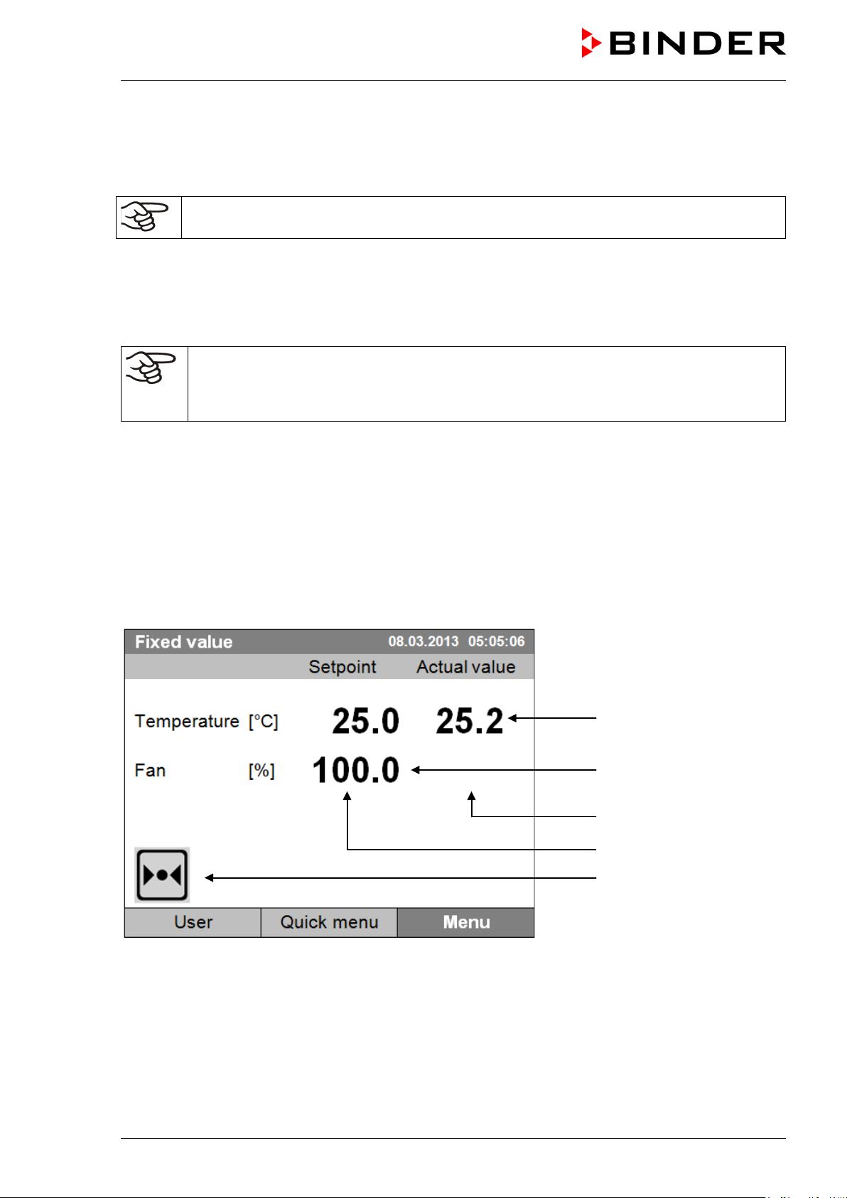
Temperature values
Fan speed value
Actual values
Set-point values
Icons:
Controller operating in “fixed
value” operating mode
Figure 8: T4.12 microprocessor controller, initial view in “fixed value” controller mode (sample values)
KT (E6) 09/2013 Page 23/135
Page 24
Fixed value
Setpoint
Actual value
25.0
25.2
100.0
Fixed value
..\ Menu
Controller mode
Event list
Alarms
Setpoints
Safety controller
Programs
Import/Export
Settings
6.1 Menu structure
08.03.2013 05:05:06
Temperature [°C]
Fan [%]
User Quick menu
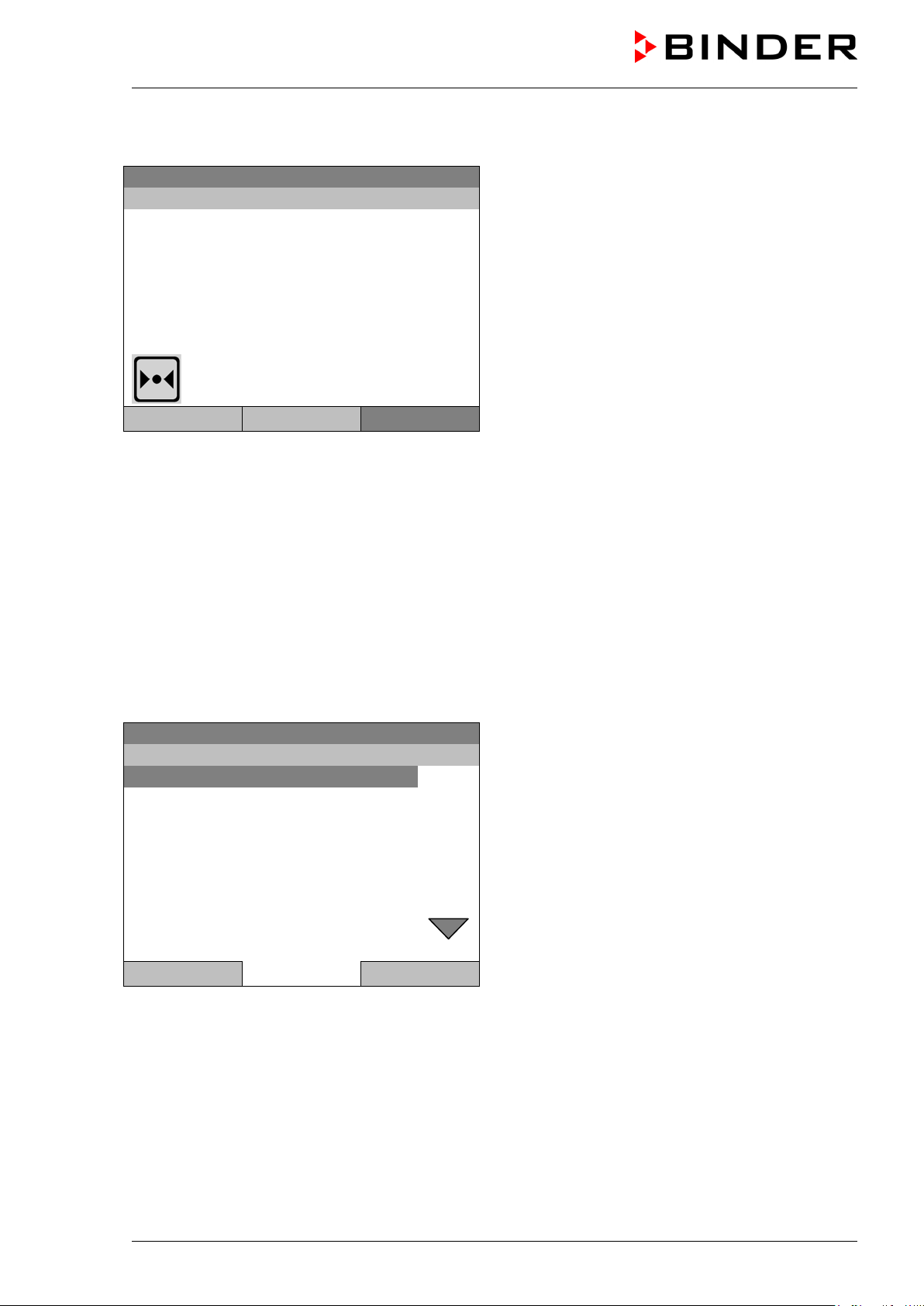
From the Initial view you have access to different menus using the menu buttons “User”, “Quick menu”, or
“Menu”. From there you can access the desired control functions. To do this, select the function by
turning the operating button and press the operating button to confirm the selection.
In any menu, you can return to the previous display pressing the "Close" button or to the initial view with
the "Home" button.
Depending on the logged-in user or administrator, the available menu functions may vary. These
instructions present the functions which are available to the logged-in administrator.
Menu
Initial view (sample values).
Press the desired menu button.
6.1.1 General menu
The general menu provides access to all setting functions of the controller, a graphical display of the
measured values, and the possibility to read and give out data via the USB interface. In addition,
supporting functions like a settings wizard or a contact page are available.
08.03.2013 05:05:06
General menu
Close Home
Turn the operating button to see additional menu items.
KT (E6) 09/2013 Page 24/135
Page 25
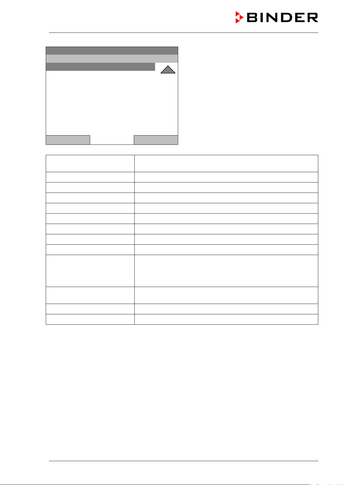
Fixed value
..\ Menu
Measurement chart
Optional equipment
Sensor adjustment
Service contact
System information
08.03.2013 05:05:06
General menu (next page)
(“Optional equipment” menu item is visible only with
optional unit equipment)
Close Home
Controller mode
Event list
Alarms
Setpoints
Safety controller
Programs
Import/Export
Settings
Measurement chart
Switching between the operating modes “control off” or “fixed value”,
chap. 6.2.1
Display of status information and errors, chap. 15
Alarm settings, chap. 14.4
Setpoint entry in “Fixed value” operating mode, chap. 8
Setting the safety controller, chap. 17.2
Time and week programs, chap. 9 and 10
Data transfer via USB interface, chap. 13
General controller settings, chap. 12
Graphical display of the measured values, chap. 16
Setting for optional equipment like door heating, interior socket,
Optional equipment
zero-voltage relay control outputs, alarm output, object temperature
display, chap. 7
(menu item is visible only with optional unit equipment)
Sensor adjustment
Adjustment menu for single-point and two-point adjustments (for
Service purpose)
Service contact Service information
System information Chamber information (model, name, serial no., firmware etc.)
KT (E6) 09/2013 Page 25/135
Page 26
Fixed value
..\ Quick menu
Measurement chart
Active alarms
Temperature setpoint
Fan speed setpoint
Safety controller setpoint
Time program
Week program
Fixed value
..\ User
Key lock
Show event list
6.1.2 Quick menu
The Quick menu provides fast access to frequently used functions.
08.03.2013 05:05:06
“Quick menu”
Close Home
Measurement chart
Active alarms
Temperature setpoint
Fan speed setpoint
Safety controller setpoint
Time program
Week program
Graphical display of the measured values, chap. 16
Alarm settings, chap. 14.4
Temperature setpoint entry in “Fixed value” operating mode, chap. 8
Fan speed setpoint entry in “Fixed value” operating mode, chap. 8
Setting the safety controller setpoint, chap. 17.2
Starting and cancelling a time program, chap. 9.1, 9.2
Starting and cancelling a week program, chap. 10.1, 10.2
6.1.3 “User” menu
The user menu includes the key lock function and provides quick access to the event list. The key lock
function serves to block the access to the controller. An overview of logon, logoff, and other events is
given in the event list.
08.03.2013 05:05:06
Close Home
Key lock Configuring the key lock function, chap. 11
Show event list Displaying the event list, chap. 15
KT (E6) 09/2013 Page 26/135
“User” menu
Page 27

Fixed value
..\ Menu
Controller mode
Event list
Alarms
Setpoints
Safety controller
Programs
Import/Export
Settings
Fixed value
..\ Controller mode
Control off
Fixed value
6.2 Operating modes
In the “control off” mode (chap. 6.2.1), the controller is non-functional and displays only the actual
values. There is no heating or refrigeration. The temperature approximates the ambient value, the fan
turns with 40 % speed.
You can enter the desired set point values in “fixed value” mode (chap. 8). The controller then operates
as a fixed-point control, i.e., it reaches and maintains the defined temperature set-point until the next
manual change.
The T4.12 program controller also permits running a time program (chap. 9) or a week program (chap.
10). You can program temperature cycles and define also the fan speed for each program section. The
controller offers 52 time program places with up to 100 sections each. The week program mode offers 8
week program places with up to 30 shift points for each week program.
6.2.1 Activating the “control off” mode or change to “fixed value” operating mode
To select the “control off” or “fixed value” operating mode, go to Menu > Controller mode
08.03.2013 05:05:06
Close Home
08.03.2013 05:05:06
Close Home
General menu.
Select “Controller Mode”
and press the operating button.
Submenu “Controller Mode”.
Select the desired controller mode
“Control off” or “Fixed value”
and press the operating button.
KT (E6) 09/2013 Page 27/135
Page 28
Control off
..\ Menu
Controller mode
Event list
Alarms
Setpoints
Safety controller
Programs
Import/Export
Settings
Control off
Actual value
25.2
40.0
Menu
08.03.2013 05:05:06
General menu with controller mode “Control off”.
The controller mode “Fixed value” or “Control off” is
indicated in the display headline.
Close Home
Go back to the initial view with “Home”.
08.03.2013 05:05:06
Temperature [°C]
Fan [%]
User Quick menu
The controller is non-functional, i.e., there is no heating or refrigerating. The fan turns at 40 % speed.
In the “Control off” mode, no program can be started.
Initial view in “Control off” mode
(sample picture).
KT (E6) 09/2013 Page 28/135
Page 29

6.3 Performance during and after power failure
During a power failure, all controller functions are shut down. The optional zero-voltage relay alarm output
(chap. 19.4) is switched to alarm position for the whole duration of the power failure.
After the power returns, all functions return to the same status the chamber had before power failure. .
The controller continues to function in the original operating mode it was in previously before the power
failure occurred.
• Performance after power failure in “fixed value” operation mode
All functions return to the same status the chamber had before power failure. The set-points are
immediately resumed.
• Performance after power failure during time program operation
The program is resumed at the point where the interruption occurred with the latest set-points reached
during the program run.
• Performance after power failure during week program operation
The week program continues with the values corresponding to the current time.
If the temperature has dropped below the alarm limit during power failure, confirm the alarm with the
RESET button as soon as the correct values are reached again (chap. 14.3).
KT (E6) 09/2013 Page 29/135
Page 30
Fixed value
..\ System information
Chamber type: KT
Chamber name: KT_E6
Serial number: 00-00000
Special application number: 00-0000
Date of production (YY/MM/DD): 2012/01/01
Parameter version: 511B-0002-001A
Firmware version (1): 521C-0001-0022
Firmware version (2): 521B-0005-0017
Fixed value
..\ Service contact
Service hotline
International:
+49 7462 2005 555
USA Toll Free:
+ 1 866 885 9794 or
+ 1 631 224 4340
CIS:
+ 7 495 988 1517
service@binder-world.com
www.binder-world.com
6.4 Information
You access chamber information like the chamber type, serial no., firmware version etc. To display the
system information, go to Menu > System information
08.03.2013 05:05:06
Submenu “System information” (sample values).
Close Home
To display the BINDER Service contact data, go to Menu > Service contact
08.03.2013 05:05:06
Submenu “Service contact”.
Close Home
Further information windows are accessible under Menu > Settings > Network settings > Show
network settings (chap. 12.9) and – for service purpose – under Menu > Settings > Chamber
configuration (chap. 12.12).
KT (E6) 09/2013 Page 30/135
Page 31

Fixed value
..\ Optional equipment
Door heating
Interior socket
Zero-voltage relay control outputs
Alarm output temperature
Object temperature display
Fixed value
..\ Door heating On/Off
Door heating On
Door heating Off
Door heating Offset
1
[°C]
1 2 3 4 5 6 7 8 9 ,
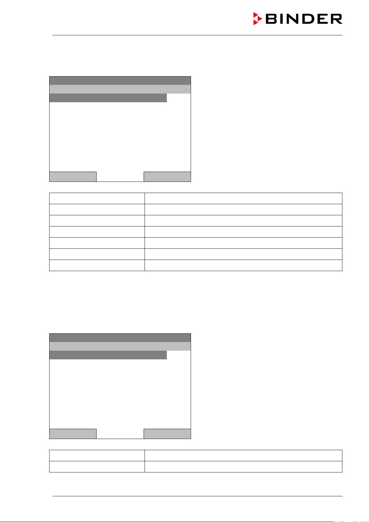
7. Configuration of optional equipment
The “Optional equipment” menu item is visible only with optional unit equipment.
To access the selection menu, go to Menu > Optional equipment
08.03.2013 05:05:06
Submenu “Optional equipment”.
Select the desired function
and press the operating button.
Close Home
7.1 Setting the optional door heating
For chambers equipped with an optional door heating, you can turn it on and off via the controller. You
can also set the door heating offset to the temperature set-point.
To access the door heating setting menu, go to Menu > Optional equipment > Door heating
08.03.2013 05:05:06
Submenu “Door heating”.
Select the desired function
and press the operating button.
Door heating On = door heating turned on
Door heating Off = door heating turned off
Door heating Offset = Temperature difference to the
entered setpoint
Close Home
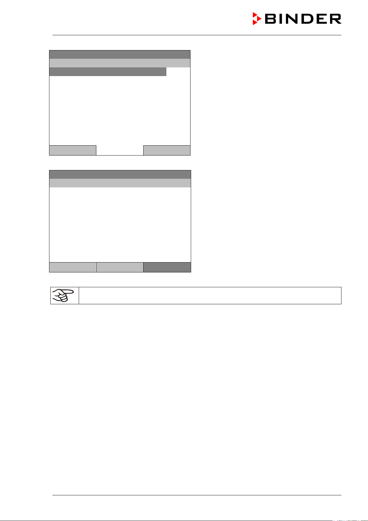
Setting the offset value:
Fixed value
..\ Door heating \ Offset
Ins Pos1 End Ok
0
Close Ok Home
08.03.2013 05:05:06
Entry menu „Offset“.
Select each number with the operating button and
press the operating button to confirm.
Setting range: 0 °C up to 5 °C.
Press the “Ok” button to confirm.
KT (E6) 09/2013 Page 31/135
Page 32

Fixed value
..\ Interior socket
Socket On
Socket Off
Fixed value
..\ Zero-voltage relay control outputs
Control output 1: Off
Control output 2: Off
Control output 3: Off
A symbol on the controller display indicates the switching state of the three zero-voltage relay
(example: control outputs 1 + 2 activated)
Go back to the initial view with “Home”.
This symbol on the controller display indicates that the door heating is active.
7.2 Turning on / off the optional interior socket
For chambers equipped with the water-protected interior socket (option, chap. 19.6) you can turn on and
off the voltage of the interior socket via the controller.
To access the setting menu, go to Menu > Optional equipment > Interior socket
08.03.2013 05:05:06
Submenu “Interior socket”.
Select the desired setting
and press the operating button.
“Socket On” = socket with activated voltage
“Socket Off” = socket voltage-free
Close Home
Go back to the initial view with “Home”.
This symbol on the controller display indicates that the interior socket is activated.
7.3 Switching on or off the optional zero-voltage relay control outputs
For units equipped with zero-voltage relay outputs (option, chap. 19.5), you can switch on or off the
output via the controller.
To access the setting menu for the operating modes “Fixed value” and “Control off”, go to
Menu > Optional equipment > Zero-voltage relay control outputs.
The setting for program operation is done through the program editor (chap. 9.3.7).
08.03.2013 05:05:06
Submenu “Zero-voltage relay control outputs”.
The current switching state of the zero-voltage relay
control outputs is indicated. To change it, select the
desired control output
and press the operating button.
The modified switching state is displayed.
“Control output On” = zero-voltage relay output
activated
Close Home
“Control output Off” = zero-voltage relay output
deactivated
Go back to the initial view with “Home”.
control outputs, as soon as at least one control output is activated
KT (E6) 09/2013 Page 32/135
Page 33

Fixed value
..\ Alarm output temperature
Functional test – Alarm output On
Functional test – Alarm output Off
Fixed value
..\ Object temperature display
Object temperature display On
Object temperature display Off
7.4 Functional test of the optional alarm output
For units equipped with the zero-voltage relay alarm output (option, chap. 19.4), you can switch on the
output for test purpose via the controller and then switch it off again.
To access the setting menu, go to Menu > Optional equipment > Alarm output temperature
08.03.2013 05:05:06
Submenu „Alarm output temperature“.
Select the desired switching state
and press the operating button.
“Functional test – Alarm output On” = alarm output
switched on (alarm state)
“Functional test – Alarm output Off” = alarm output
switched off
Close Home
Go back to the initial view with “Home”.
7.5 Switching on or off the optional object temperature display
For units equipped with the digital object temperature display with a flexible Pt 100 temperature sensor
(option, chap. 19.8), you can switch on or off the object temperature indication via the controller.
To access the setting menu, go to Menu > Optional equipment > Object temperature display
08.03.2013 05:05:06
Submenu “Object temperature display”.
Select the desired setting
and press the operating button.
„Object temperature display On“ = Object
temperature display activated
“Object temperature display Off” = Object
temperature display deactivated
Close Home
Go back to the initial view with “Home”.
KT (E6) 09/2013 Page 33/135
Page 34

Fixed value
..\ Quick menu
Measurement chart
Active alarms
Temperature setpoint
Fan speed setpoint
Safety controller setpoint
Time program
Week program
When trying to enter a setpoint in the „Controller off“ operating mode, a notification window
shows “Controller mode is OFF!”. Press the operating button to confirm with “Ok” and change
8. Set-point entry in “Fixed value” operating mode
8.1 Setting ranges:
Temperature
Fan speed
When you changed the temperature set-point, check the setting of the overtemperature safety
controller class 3.1 (chap. 17.2) or the over-/undertemperature safety controller class 3.3
(option, chap. 17.3).
With set-point type “Limit”, adapt the safety controller always when changing the temperature
set-point.
4 °C / 23 °F up to +100 °C / 212 °F
40 % up to 100 % (full speed)
Reduce the fan speed only if required, because the spatial distribution of temperature
will also be reduced.
Technical data refers to 100% fan speed.
8.2 Entering the set-points via “quick menu”
To enter set-points via quick menu, go to Quick menu.
08.03.2013 05:05:06
Close Home
the operating mode to “Fixed value” (chap. 6.2.1).
“Quick menu”.
Select the desired parameter
and press the operating button.
KT (E6) 09/2013 Page 34/135
Page 35

2
[°C]
Fixed value
..\ Fan speed setpoint
1
[%]
Temperature setting
To enter the temperature setpoint, go to Quick menu > Temperature setpoint
Fixed value
08.03.2013 05:05:06
..\ Temperature setpoint
Entry menu “Temperature setpoint”.
End Ok 0 1 3 4 5 6 7 8 9 . -
2
Select each number with the operating button and
press the operating button to confirm.
Setting range: 4 °C / 23 °F up to +100 °C / 212 °F
Press the “Ok” button to confirm.
Close Ok Home
When entering a value outside the setting range, the message “invalid value” appears. Press the
operating button to confirm with “Ok” and repeat the entry with a correct value.
Go back to the initial view with “Home” or enter the fan speed.
Fan speed setting
To enter the fan speed setpoint, go to Quick menu > Fan speed setpoint
08.03.2013 05:05:06
Entry menu “Fan speed setpoint”.
Pos1 End Ok 0 2 3 4 5 6 7 8 9 , -
1
Select each number with the operating button and
press the operating button to confirm.
Setting range: 40 % up to 100 %
Press the “Ok” button to confirm.
Close Ok Home
When entering a value outside the setting range, the message “invalid value” appears. Press the
operating button to confirm with “Ok” and repeat the entry with a correct value.
Go back to the initial view with “Home”.
When operating the fan with less than 100 % speed, the temperature performance and the
spatial exactitude of the temperature may differ from the manufacturer’s specifications. Do
reduce the fan speed only if absolutely necessary due to special requirements.
KT (E6) 09/2013 Page 35/135
Page 36

Fixed value
..\ Setpoints
Temperature
Fan speed
Fixed value
..\ Temperature setpoint
2
[°C]
8.3 Entering the set-points via general menu
To enter set-points via general menu, go to Menu > Setpoints
08.03.2013 05:05:06
Submenu “Setpoints”.
Select “Temperature” or “Fan speed”
and press the operating button.
Close Home
Temperature setting
To enter the temperature setpoint, go to Menu > Setpoints > Temperature
08.03.2013 05:05:06
Entry menu “Temperature setpoint”.
Pos1 End Ok 0 1 3 4 5 6 7 8 9 , -
2
Select each number with the operating button and
press the operating button to confirm.
Setting range: 4 °C / 23 °F up to +100 °C / 212 °F
Press the “Ok” button to confirm.
Close Ok Home
When entering a value outside the setting range, the message “Invalid value” appears. Press the
operating button to confirm with “Ok” and repeat the entry with a correct value.
Go back to the initial view with “Home” or enter the fan speed.
KT (E6) 09/2013 Page 36/135
Page 37

1
[%]
Fan speed setting
To enter the fan speed setpoint, go to Menu > Setpoints > Fan speed
Fixed value
08.03.2013 05:05:06
..\ Fan speed setpoint
Entry menu “Fan speed setpoint”.
Pos1 End Ok 0 2 3 4 5 6 7 8 9 . -
1
Select each number with the operating button and
press the operating button to confirm.
Setting range: 40 % up to 100 %
Press the “Ok” button to confirm.
Close Ok Home
When entering a value outside the setting range, the message “invalid value” appears. Press the
operating button to confirm with “Ok” and repeat the entry with a correct value.
Go back to the initial view with “Home”.
When operating the fan with less than 100 % speed, the temperature performance and the
spatial exactitude of the temperature may differ from the manufacturer’s specifications. Do
reduce the fan speed only if absolutely necessary due to special requirements.
KT (E6) 09/2013 Page 37/135
Page 38

Fixed value
Setpoint
Actual value
25.0
25.2
100.0
Fixed value
..\ Menu
Controller mode
Event list
Alarms
Setpoints
Safety controller
Programs
Import/Export
Settings
Fixed value
..\ Programs
Time program
Week program
9. Time programs
The T4.12 program controller permits programming temperature cycles. It offers 52 program memory
positions with up to 100 program sections each.
To access the menu selection for time programs, select Menu > Programs > Time program
08.03.2013 05:05:06
Temperature [°C]
Fan [%]
User Quick menu
08.03.2013 05:05:06
Close Home
08.03.2013 05:05:06
Initial view.
Press the “Menu” button.
Menu
General menu.
Select “Programs”
and press the operating button
Submenu “Programs”.
Select “Time Program”
and press the operating button
Close Home
KT (E6) 09/2013 Page 38/135
Page 39

Fixed value
..\ Programs\Time programs
Start
Stop
Pause
Resume
Edit
Create
Rename
Delete
Fixed value
..\ Programs\Time programs
Delete all
08.03.2013 05:05:06
Submenu “Time programs”.
Turn the operating button to see additional menu
items.
Close Home
08.03.2013 05:05:06
Close Home
Submenu “Time programs” (next page)
KT (E6) 09/2013 Page 39/135
Page 40

Fixed value
..\ Programs\Time programs
Start
Stop
Pause
Resume
Edit
Create
Rename
Delete
Fixed value
..\ Select program
Program0001
Program0002
Program0003
Fixed value
0
8.03.2013
3 4 5 6 7 8 9
9.1 Starting and running an existing time program
To start a time program, go to Menu > Programs > Time program > Start.
(You can also go to Quick menu > Time program > Start , see below).
Starting is also possible directly from the program editor (chap. 9.3.9).
In the “Control off” mode or during a running time or week program, no time program can be
started.
08.03.2013 05:05:06
Submenu “Time program”.
Select “Start” to start an existing program
and press the operating button.
Close Home
If no program has been created and saved so far, the message “No programs found” appears. Press the
operating button to confirm with “Ok” and enter a program with “Create”.
08.03.2013 05:05:06
Submenu “Select program” (example).
Select one of the programs
and press the operating button to run the program
Close Home
08.03.2013 05:05:06
..\ Start date (DD.MM.YYYY)
Entry menu “Start date”.
Ins Pos1 End Ok 1 2
0
The current date is shown. For a postponed start,
enter the desired start date with the operating
button.
Press the “Ok” button to confirm.
Close Ok Home
KT (E6) 09/2013 Page 40/135
Page 41

0
Time program
08.03.2013 05:05:06
10.0
11.5
Section 20 End: 08.03.2013 08:07:44
100.0
Menu
Fixed value
08.03.2013 05:05:06
..\ Start time (HH:MM:SS)
Ins Pos1 End 1 2 3 4 5 6 7 8 9
0
Close Ok Home
Program0001
Setpoint Actual value
Temperature [°C]
Fan [%]
Entry menu “Start time”.
The current time plus 30 seconds is shown. For a
postponed start, enter the desired start time with the
operating button.
Press the “Ok” button to confirm.
Initial view (example values).
The time program is running.
User Quick menu
This symbol on the controller display indicates that a time program is running.
During a running time program, it is impossible to edit, rename or delete this program (when selecting
such a function, a corresponding message is displayed). The other program functions are available.
During a running time program, no week program can be started.
KT (E6) 09/2013 Page 41/135
Page 42

Fixed value
..\ Quick menu
Measurement chart
Active Alarms
Temperature setpoint
Fan speed setpoint
Safety controller setpoint
Time program
Week program
Fixed value
..\ Time program
Start
Stop
Fixed value
..\ Select program
Program0001
Program0002
Program0003
To start a time program, you can also go to Quick menu > Time program > Start
08.03.2013 05:05:06
“Quick menu”.
Select “Time program”
and press the operating button
Close Home
08.03.2013 05:05:06
Submenu “Time program”.
Select “Start” to start an existing program
and press the operating button.
Close Home
The further procedure is equal to that described for the general menu.
08.03.2013 05:05:06
Submenu “Select program” (example).
Select one of the programs
and press the operating button to start the program
Close Home
KT (E6) 09/2013 Page 42/135
Page 43

Performance after completing the program
The controller automatically changes to the “Fixed value” operation mode.
Before starting the program, check the temperature setpoint entered in the “Fixed value” operation mode.
After end of the program, the temperature will equilibrate to this value.
CAUTION
Too high or too low temperature after the program ends.
Damage to the charging material.
Check the temperature setpoint of “Fixed value” operation and if necessary adapt it.
9.2 Cancelling a running time program
To cancel a running time program, go to Menu > Programs > Time program > Stop.
To cancel a running time program, you can also go to Quick menu > Time program > Stop.
The controller returns to the initial view.
Performance after manual program stop
The controller automatically changes to the “Fixed value” operation mode.
Before starting a program, check the temperature setpoint entered in the “Fixed value” operation mode.
After cancelling the program, the temperature will equilibrate to this value.
CAUTION
Too high or too low temperature after cancelling the program.
Damage to the charging material.
Check the temperature setpoint of “Fixed value” operation and if necessary adapt it.
KT (E6) 09/2013 Page 43/135
Page 44

Fixed value
..\ Programs\Time programs
Start
Stop
Pause
Resume
Edit
Create
Rename
Delete
Fixed value
..\ Create new program
New
Based on…
9.3 Creating a new time program
For each program section you can enter a temperature set-point, the fan speed, the section’s duration,
the type of temperature transition “R” (ramp) or “S” (step) (see chap. 9.3.6), and the tolerance range.
When changing the temperature set-point, check the setting of the safety controller (chap. 17)
if the safety controller has been set to “limit” mode.
If the fan is operated with less than 100 % speed, the temperature performance and the
spatial exactitude of the temperature can differ from the manufacturer’s specifications. The fan
speed rate should only be reduced if absolutely necessary to meet special requirements.
Programming is saved in case of a power failure or after turning off the unit.
To enter a new time program, go to Menu > Programs > Time programs > Create
08.03.2013 05:05:06
Close Home
Creating a new program
08.03.2013 05:05:06
Submenu “Time program”.
Select “Create"
and press the operating button.
Submenu “Create new program”.
Select “New", to create an entirely new program, or
“Based on”, to use an existing program for further
editing
and press the operating button.
Close Home
KT (E6) 09/2013 Page 44/135
Page 45

Fixed value
..\ Select program
Program0001
Program0002
Program0003
Enter name
..\ Program
Fixed value
..\ Temperature controller
No.
Value
H:M:S
Ref.
Rep.
T. min
T.max
R/S
1
25.00
00:00:15
1 0 -999.00
999.00
Ramp
If you selected “Based on”, then the program selection window appears:
08.03.2013 05:05:06
Submenu “Select program” (example).
Select the desired program
and press the operating button.
Close Home
If no program has been created and saved so far, the message “No programs found” appears. Press the
operating button to confirm with “Ok” and enter a program with “Create”.
Now you can specify the name of the new time program:
08.03.2013 05:05:06
T U V W X Y Z 1 2 3 4 5 6 7 8 9
0
Entry menu “Program”.
Enter the desired start time with the operating
button.
Press the “Ok” button to confirm.
Close Ok Home
The time program editor is displayed. Following the selection “Based on”, this table for program entry
shows the values of the selected program. Following the selection “Empty program" there is an empty
table, which can be filled section by section with sample values. You can edit the displayed values.
Entering the program values for the first parameter (temperature)
A first program line is shown. This corresponds to a program section. You can now edit the values.
08.03.2013 05:05:06
KT (E6) 09/2013 Page 45/135
Time program editor
(view with optional control outputs).
To edit the values, press the operating button, select
the desired value and press the operating button
again.
Menu
Page 46

Fixed value
..\ Temperature controller
No.
Value
H:M:S
Ref.
Rep.
T. min
T.max
R/S
1
25.00
00:00:15
1 0 -999.00
999.00
Ramp
2
25.00
00:00:15
1 0 -999.00
999.00
Ramp
3
25.00
00:00:15
1 0 -999.00
999.00
Ramp
Fixed value
..\ Temperature controller
No.
Value
H:M:S
Ref.
Rep.
T. min
T.max
R/S
1
25.00
00:00:15
1 0 -999.00
999.00
Ramp
Fixed value
..\ Program sections
Insert
Copy
Paste
Delete
To create a second program line (section), turn the operating button to the right and press it. The next
section will be added.
08.03.2013 05:05:06
Time program editor
(view with optional control outputs).
To edit the values, press the operating button, select
the desired value and press the operating button
again.
Menu
The right column for the 3 control outputs is visible only on units equipped with optional control outputs.
9.3.1 Section handling
08.03.2013 05:05:06
Time program editor.
Select a value under “No.”
and press the operating button.
08.03.2013 05:05:06
Submenu “Program sections“.
Select the desired function
and press the operating button.
Close
Note: When selecting „Insert“ or “Paste”, the new program section is inserted before the current section.
KT (E6) 09/2013 Page 46/135
Page 47

Fixed value
..\ Temperature controller
[°C]
No.
Value
H:M:S
Ref.
Rep.
T. min
T.max
R/S
1
25.00
00:00:15
1 0 -999.00
999.00
Ramp
..\ Temperature setpoint
2
[°C]
Fixed value
..\ Temperature controller
[°C]
No.
Value
H:M:S
Ref.
Rep.
T. min
T.max
R/S
1
25.00
00:00:15
1 0 -999.00
999.00
Ramp
Fixed value
0
0:00:15
9.3.2 Temperature setpoint
08.03.2013 05:05:06
Time program editor.
Select a value under “Value”
and press the operating button.
08.03.2013 05:05:06
Entry menu “Temperature setpoint”.
Pos1 End Ok 0 1
3 4 5 6 7 8 9 , -
2
A temperature value is shown. Enter the desired
value with the operating button.
Setting range: 4 °C up to 100 °C.
Press the “Ok” button to confirm.
Close Ok
When entering a value outside the setting range, the message “invalid value” appears. Press the
operating button to confirm with “Ok” and repeat the entry with a correct value.
9.3.3 Section duration
08.03.2013 05:05:06
08.03.2013 05:05:06
..\ Section duration
Ins Pos1 End Ok 1 2 3 4 5 6 7 8 9
0
Close Ok
Time program editor.
Select a value under “H:M:S”
and press the operating button.
Entry menu “Section duration”.
A duration value is shown. Enter the desired value
with the operating button.
Press the “Ok” button to confirm.
KT (E6) 09/2013 Page 47/135
Page 48

Fixed value
..\ Temperature controller
[°C]
No.
Value
H:M:S
Ref.
Rep.
T. min
T.max
R/S
1
25.00
00:00:15
1
0
-999.00
999.00
Ramp
Fixed value
..\ Reference section
1
Fixed value
..\ Temperature controller
[°C]
No.
Value
H:M:S
Ref.
Rep.
T. min
T.max
R/S
1
25.00
00:00:15
1 0 -999.00
999.00
Ramp
0
9.3.4 Repeating one or several sections within a time program
Enter the number of the target section, which shall be the start of the repeat cycle, under “Ref.” and the
number of repeats under “Rep.”. To have sections repeated infinitely enter the number of cycles “Rep.” as
“-1”.
08.03.2013 05:05:06
08.03.2013 05:05:06
Pos1 End Ok 0 2 3 4 5 6 7 8 9 ,
1
Close Ok
Continue to enter the number of repeats:
Time program editor.
Select a value under “Ref.”
and press the operating button.
Entry menu “Reference section”.
Enter the target section number of the repeat cycle
with the operating button.
Press the “Ok” button to confirm.
08.03.2013 05:05:06
Fixed value
08.03.2013 05:05:06
..\ Number of repeats
Del Pos1 End Ok
1 2 3 4 5 6 7 8 9
0
Close Ok
Time program editor.
Select a value under “Rep.”
and press the operating button.
Entry menu “Number of repeats”.
Enter the desired number of repeats with the
operating button.
Press the “Ok” button to confirm.
KT (E6) 09/2013 Page 48/135
Page 49

Fixed value
..\ Temperature controller
[°C]
No.
Value
H:M:S
Ref.
Rep.
T. min
T.max
R/S
1
40.00
00:30:00
1 0 -999.00
999.00
Ramp
2
60.00
01:30:00
1 0 -999.00
999.00
Ramp
3
80.00
01:00:00
2
30
-999.00
999.00
Ramp
4
20.00
03:20:00
1 0 -999.00
999.00
Ramp
Fixed value
..\ Temperature controller
[°C]
No.
Value
H:M:S
Ref.
Rep.
T. min
T.max
R/S
1
25.00
00:00:15
1
0
-999.00
999.00
Ramp
Fixed value
-
999.00
[°C]
The following example shows a time program where the sections 2 and 3 shall be repeated 30 times:
08.03.2013 05:05:06
Time program editor.
Menu
Sections 2 and 3 will be executed in total 31 times; only then will the program continue.
9.3.5 Tolerance range
You can specify a tolerance range for each program section with different values for the tolerance
minimum and maximum. When the actual value exceeds the given threshold, the program is interrupted.
This is indicated on the display, see chap. 9.4. When the actual temperature is situated again within the
entered tolerance limits, the program automatically continues. Therefore, the duration of the program may
be extended due to the programming of tolerances.
Programming of tolerances may extend program duration.
An entry of “-999” for the tolerance minimum means “minus infinite” and an entry of “999” for the tolerance
maximum means “plus infinite”. Entry of these values will never lead to program interruption.
When requesting a rapid temperature transition, we recommend not programming tolerance values in
order to enable the maximum heating-up or cooling-down speed.
Start with the minimum value:
08.03.2013 05:05:06
Time program editor.
Select a value under “T. min”
and press the operating button.
08.03.2013 05:05:06
..\ Tolerance range minimum temperature
2 3 4 5 6 7 8 9 , Del Ins Pos1
-
Entry menu “Tolerance range minimum
temperature”.
Enter the desired value with the operating button.
Press the “Ok” button to confirm.
Close Ok
KT (E6) 09/2013 Page 49/135
Page 50

Fixed value
..\ Temperature controller
[°C]
No.
Value
H:M:S
Ref.
Rep.
T. min
T.max
R/S
1
25.00
00:00:15
1 0 -999.00
999.00
Ramp
9
99.00
[°C]
Continue to enter the maximum value:
08.03.2013 05:05:06
Fixed value
08.03.2013 05:05:06
..\ Tolerance range maximum temperature
0 1 2 3 4 5 6 7 8 , - Del Ins Pos1
9
Close Ok
Time program editor.
Select a value under “T. max”
and press the operating button.
Entry menu “Tolerance range maximum
temperature”.
Enter the desired value with the operating button.
Press the “Ok” button to confirm.
KT (E6) 09/2013 Page 50/135
Page 51

Fixed value
..\ Temperature controller
[°C]
1
25.00
00:00:15
1 0 -999.00
999.00
Ramp
Fixed value
..\ Ramp/step
Ramp
Step
9.3.6 Set-point ramp and set-point step modes
“Ramp” mode
The set-point of a given program section functions as the section’s start temperature. During the section’s
duration, the temperature set-point gradually passes to the set-point of the subsequent program section.
The actual temperature value follows the continually changing set-point. If the last program section is in
“ramp” mode, then you must program an additional section to provide the target temperature. Otherwise,
the corresponding section would be incomplete, i.e., the program would stop one section too early.
Programming in the “ramp” mode allows various kinds of temperature transitions:
• Gradual slow temperature changes
The set-point changes its value gradually during the entered section duration. The actual temperature
value (X) follows the continually moving set-point (W) at any time.
• Constant temperature
The initial values of two subsequent program sections are identical; so the temperature remains
constant during the duration of the first program section.
• Sudden temperature changes
These changes occur rapidly within the minimum amount of time (minimum entry: 1 second).
“Step” mode
The set-point of any program section functions as the section’s target temperature. At the start of the
program section, the unit heats up or cools down with the maximum speed to reach the entered value;
and then it holds it for the remaining section time. The set-point temperature remains constant for the
section’s duration.
08.03.2013 05:05:06
No. Value H:M:S Ref. Rep. T. min T.max R/S
Time program editor.
Select a value under “R/S”
and press the operating button.
08.03.2013 05:05:06
Submenu “Ramp/step“.
Select the desired function
and press the operating button.
“Ramp” = Setpoint ramp mode selected
“Step” = Setpoint step mode selected
Close
KT (E6) 09/2013 Page 51/135
Page 52

W/°C
t/min.
01
02
03
04
0
20
40
60
80
100
30
120
180
380
05
No.
Value
H:M:S
Ref.
Rep.
T. min
T.max
R/S
01
40.0
00:30:00
1 0 -999
+999
Ramp
02
60.0
01:30:00
1 0 -5
+5
Ramp
03
80.0
01:00:00
1 0 -2
+2
Ramp
04
80.0
03:20:00
1 0 -999
+999
Ramp
05
20.0
00:00:01
1 0 -999
+999
Ramp
W/°C
t/min.
01 02 03 04
0
20
40
60
80
100
30
120
180
380
No.
Value
H:M:S
Ref.
Rep.
T. min
T.max
R/S
01
40.0
00:30:00
1 0 -999
+999
Step
02
60.0
01:30:00
1 0 -5
+5
Step
03
80.0
01:00:00
1 0 -2
+2
Step
04
20.0
03:20:00
1 0 -999
+999
Step
Examples:
“Ramp” mode
Corresponding program table:
“Step” mode
Corresponding program table
KT (E6) 09/2013 Page 52/135
Page 53

Fixed value
..\ Temperature controller
[°C]
No.
Value
H:M:S
Ref.
Rep.
T. min
T.max
R/S
1
25.00
00:00:15
1 0 -999.00
999.00
Rampe
Fixed value
..\ Zero -voltage relay outputs
Outputs 1 [Off] 2[Off] 3[Off]
Outputs 1[On] 2[Off] 3[Off]
Outputs 1[Off] 2[On] 3[Off]
Outputs 1[Off] 2[Off] 3[On]
Outputs 1[On] 2[Off] 3[On]
Outputs 1[Off] 2[On] 3[On]
Outputs 1[On] 2[On] 3[On]
9.3.7 Switching on or off the optional zero-voltage relay outputs
For units equipped with zero-voltage relay outputs (option, chap. 19.5), you can switch on or off the
outputs for each program section via the program editor.
08.03.2013 05:05:06
Close
A symbol on the controller display indicates the switching state of the three zero-voltage relay
outputs (example: outputs 1 + 2 turned on)
08.03.2013 05:05:06
Time program editor (with option relay outputs)
Select a field under „
“
and press the operating button.
Submenu “Zero -voltage relay outputs”.
The possible combination of switching states are
indicated.
Select the desired combination of switching states
and press the operating button.“
[On] = zero-voltage relay outputs turned on
[Off] = zero-voltage relay outputs turned off
KT (E6) 09/2013 Page 53/135
Page 54

Fixed value
..\ Temperature controller
[°C]
No.
Value
H:M:S
Ref.
Rep.
T. min
T.max
R/S
1
40.00
00:30:00
1 0 -999.00
999.00
Step
2
60.00
01:30:00
1 0 -5.00
5.00
Step
3
80.00
01:00:00
1 0 -5.00
5.00
Step
4
20.00
03:20:00
1 0 -999.00
999.00
Step
5
40.00
00:30:00
1 0 -999.00
999.00
Step
6
60.00
01:30:00
1 0 -5.00
5.00
Step
7
70.00
01:00:00
1 0 -5.00
5.00
Step
8
60.00
01:00:00
1 0 -5.00
5.00
Step
Fixed value
..\ Program menu
Select parameter
Save and exit
Save and run
Exit (without saving!)
Fixed value
..\ Program parameters
Temperature controller
Fan speed
9.3.8 Calling up the next parameter
08.03.2013 05:05:06
Time program editor (example).
Press the “Menu” button.
Menu
08.03.2013 05:05:06
Close
With the “Close” button, the controller returns to the time program editor.
Submenu “Program menu”.
Select “Select parameter”
and press the operating button.
08.03.2013 05:05:06
Submenu “Program parameters”.
Select “Fan speed main controller”
and press the operating button.
Close
KT (E6) 09/2013 Page 54/135
Page 55

Fixed value
..\ Fan speed
[%]
No.
Value
H:M:S
Ref.
Rep.
T. min
T.max
R/S
1
100.00
00:30:00
1 0 ***
***
Ramp
1
100.00
00:10:00
1 0 ***
***
Ramp
1
100.00
00:30:00
2 3 ***
***
Ramp
1
100.00
00:00:01
1 0 ***
***
Ramp
Fixed value
..\ Fan speed
[%]
No.
Value
H:M:S
Ref.
Rep.
T. min
T.max
R/S
1
100.00
00:00:15
1 0 ***
***
Ramp
1
[%]
Entering the set-point values for another parameter (fan speed)
The number of program lines (program sections) equal to the number in the temperature program is
displayed. The settings of section length, repeats and the selection „Ramp“ or „Step“ are taken over from
the temperature program; they are no editable in this view. The symbol “ *** ” indicates that there are no
tolerance value required for the fan speed. You can enter the fan speed set-points.
If you want to insert further sections or perform any other programming, first change back to
the temperature program through Menu > Select parameter > Temperature controller.
08.03.2013 05:05:06
Time program editor (example).
To edit the values, press the operating button, select
the desired value and press the operating button
again.
Menu
Entering the fan speed setpoint
08.03.2013 05:05:06
Fixed value
08.03.2013 05:05:06
..\ Fan speed setpoint
Pos1 End Ok 0
2 3 4 5 6 7 8 9 ,
1
Close Ok
Time program editor.
Select a value under “Value”
and press the operating button.
Entry menu “Fan speed setpoint”.
A fan speed value is shown. Enter the desired value
with the operating button.
Setting range: 40 % up to 100 %
Press the “Ok” button to confirm.
When entering a value outside the setting range, the message “invalid value” appears. Press the
operating button to confirm with “Ok” and repeat the entry with a correct value.
KT (E6) 09/2013 Page 55/135
Page 56

Fixed value
..\ Temperature controller
[°C]
No.
Value
H:M:S
Ref.
Rep.
T. min
T.max
R/S
1
40.00
00:30:00
1 0 -999.00
999.00
Step
2
60.00
01:30:00
1 0 -5.00
5.00
Step
3
80.00
01:00:00
1 0 -5.00
5.00
Step
4
20.00
03:20:00
1 0 -999.00
999.00
Step
5
40.00
00:30:00
1 0 -999.00
999.00
Step
6
60.00
01:30:00
1 0 -5.00
5.00
Step
7
70.00
01:00:00
1 0 -5.00
5.00
Step
8
60.00
01:00:00
1 0 -5.00
5.00
Step
Fixed value
..\ Program menu
Select parameter
Save and exit
Save and run
Exit (without saving!)
9.3.9 Saving the time program and leaving the program editor
08.03.2013 05:05:06
Time program editor (example).
Press the “Menu” button.
Menu
08.03.2013 05:05:06
Submenu “Program menu”.
Select “Save and exit”
and press the operating button.
Close
With the „Close“ button, the controller returns to the time program editor.
Select parameter Changing between temperature and fan speed.
Saving the program. The controller returns to the “Time programs”
Save and exit
submenu. You can now select and start the program as described
in chap. 9.1.
Saving the program and start it. Enter the start date and time, see
Save and run
chap. 9.1. If another time or week program is running, the program
is only saved, but not started. A corresponding message is
displayed.
Exit (without saving!)
Attention: the program is not saved. After a security question, the
controller returns to the initial view.
Button “Close”
KT (E6) 09/2013 Page 56/135
The controller returns to the time program editor. You can continue
programming.
Make sure that you saved the time program before leaving the program editor.
Page 57

Fixed value
..\ Confirm operation
Do not exit
Really exit (without saving!)
With “Exit (without saving!)” you exit the program editor without saving the program. There is a security
question first:
08.03.2013 05:05:06
Submenu “Confirm operation”.
This a security question. Select the desired function
and press the operating button.
Close
If you selected “Really exit (without saving!)”, the controller goes back to the initial view.
KT (E6) 09/2013 Page 57/135
Page 58

Time program
..\ Time program
Start
Stop
Pause
Resume
Edit
Create
Rename
Delete
Time program paused
Program0001
Setpoint
Actual value
10.0
11.5
Section 02 End: 08.03.2013 08:07:44
100.0
Time program
..\ Time program
Start
Stop
Pause
Resume
Edit
Create
Rename
Delete
9.4 Program interruption
You can manually interrupt a time program (pause), or this will automatically occur when exceeding the
entered tolerance range values of the corresponding program section (see chap. 9.3.5).
Manual program interruption
To interrupt a time program, go to Menu > Programs > Time programs > Pause
08.03.2013 05:05:06
Submenu “Time program”.
Select “Pause” to interrupt the running time program
and press the operating button.
Close Home
With button “Home” the controller returns to the initial view.
08.03.2013 05:05:06
Temperature [°C]
Initial view (example values).
Fan [%]
User Quick menu
This symbol on the controller display indicates that a running time program is interrupted.
Continuing the time program after a manual interruption
Menu
08.03.2013 05:05:06
The time program is running, but halted. The final
time (in this example: 08:07:44) is running.
Close Home
With button “Home” the controller returns to the initial view.
KT (E6) 09/2013 Page 58/135
Submenu “Time program”.
Select “Resume” to continue the time program
and press the operating button.
Page 59

Fixed value
..\ Programs\Time program
Start
Stop
Pause
Resume
Edit
Create
Rename
Delete
Fixed value
..\ Confirm operation
Do not delete
Really delete
9.5 Deleting a time program
To delete a time program, go to Menu > Programs > Time program > Delete or
Menu > Programs > Time program > Delete all
08.03.2013 05:05:06
Submenu “Time program”.
Select “Delete” or “Delete all” (next page)
and press the operating button
Close Home
If you selected “Delete”, select then the time program to be deleted and press the operating button.
If you selected “Delete all”, all time programs will be deleted in the controller.
Before deleting there is a security question:
08.03.2013 05:05:06
Submenu “Confirm operation”.
This a security question. Select the desired function
and press the operating button.
Close Home
Go back to the initial view with “Home”.
KT (E6) 09/2013 Page 59/135
Page 60

Fixed value
Setpoint
Actual value
25.0
25.2
100.0
Fixed value
..\ Menu
Controller mode
Event list
Alarms
Setpoints
Safety controller
Programs
Import/Export
Settings
Fixed value
..\ Programs
Time program
Week program
10. Week programs
The T4.12 program controller permits programming week programs with real-time reference. It offers 8
week program places in total with up to 30 shift points for each week program.
To access the menu selection for week programs, select Menu > Programs > Week program
08.03.2013 05:05:06
Temperature [°C]
Fan [%]
User Quick menu
08.03.2013 05:05:06
Close Home
08.03.2013 05:05:06
Initial view.
Press the “Menu” button.
Menu
General menu.
Select “Programs”
and press the operating button
Submenu “Programs”.
Select “Week Program”
and press the operating button
Close Home
KT (E6) 09/2013 Page 60/135
Page 61

Fixed value
..\ Programs\Week program
Start
Stop
Edit
Create
Rename
Delete
Delete all
Fixed value
..\ Select program
Program0004
Program0005
Day-Night
Fixed value
0
8.03.2013
10.1 Starting and running an existing week program
To start a week program, go to Menu > Programs > Week program > Start
(You can also go to Quick menu > Week program > Start , see below).
Starting is also possible directly from the program editor (chap. 10.3.8).
In the “Control off” mode or during a running time or week program, no week program can be
started.
08.03.2013 05:05:06
Submenu “Week program”.
Select “Start” to start an existing week program
and press the operating button
Close Home
08.03.2013 05:05:06
Submenu “Select program” (example).
Select one of the programs
and press the operating button to run the program
Close Home
If no program has been created and saved so far, the message “No programs found” appears. Press the
operating button to confirm with “Ok” and enter a program with “Create”.
08.03.2013 05:05:06
..\ Start date (DD.MM.YYYY)
Entry menu “Start date”.
End Ok 0 1 2 3 5 6 7 8 9 , - Del
4
The current date is shown. For a postponed start,
enter the desired start date with the operating
button.
Press the “Ok” button to confirm.
Close Ok Home
KT (E6) 09/2013 Page 61/135
Page 62

0
Week program
08.03.2013 05:05:06
Program0004
Setpoint
Actual value
15.0
15.3
Section: 0002 End: Sunday 00:00:00
100.0
User
Quick menu
Menu
Fixed value
08.03.2013 05:05:06
..\ Start time (HH:MM:SS)
Ins Pos1 End 1 2 3 4 5 6 7 8 9
0
Close Ok Home
Temperature [°C]
Fan [%]
Entry menu “Start time”.
The current time plus 30 seconds is shown. For a
postponed start, enter the desired start time with the
operating button.
Press the “Ok” button to confirm.
Initial view.
The week program is running.
This symbol on the controller display indicates that a week program is running.
During a running week program, it is impossible to edit, rename or delete this program (when selecting
such a function, a corresponding message is displayed). The other program functions are available.
During a running week program, no time program can be started.
KT (E6) 09/2013 Page 62/135
Page 63

Fixed value
..\ Quick menu
Measurement chart
Active Alarms
Temperature setpoint
Fan speed setpoint
Safety controller setpoint
Time program
Week program
Fixed value
..\ Week program
Start
Stop
Fixed value
..\ Select program
Program0001
Program0002
Program0003
To start a week program, you can also go to Quick menu > Week program > Start
08.03.2013 05:05:06
“Quick menu”.
Select “Week program”
and press the operating button
Close Home
08.03.2013 05:05:06
Submenu “Week program”.
Select “Start” to start an existing program
and press the operating button.
Close Home
The further procedure is equal to that described for the general menu.
08.03.2013 05:05:06
Submenu “Select program” (example).
Select one of the programs
and press the operating button to start the program
Close Home
KT (E6) 09/2013 Page 63/135
Page 64

10.2 Cancelling a running week program
To cancel a week program, go to Menu > Programs > Week program > Stop.
To cancel a running week program, you can also go to Quick menu > Week program > Stop.
The controller returns to the initial view.
Performance after manual program stop
The controller automatically changes to the “Fixed value” operation mode.
Before starting a program, check the temperature setpoint entered in the “Fixed value” operation mode.
After cancelling the program, the temperature will equilibrate to this value.
CAUTION
Too high or too low temperature after cancelling the program.
Damage to the charging material.
Check the temperature setpoint of “Fixed value” operation and if necessary adapt it.
KT (E6) 09/2013 Page 64/135
Page 65

Fixed value
..\ Programs\Week programs
Start
Stop
Edit
Create
Rename
Delete
Delete all
Fixed value
..\ Create new program
New
Based on…
10.3 Creating a new week program
A week program permits defining up to 30 sections for the whole week. These sections function as shift
points. A shift-point is characterized by its time, temperature value, and state (active / inactive). With a
running week program, the temperature of the currently active shift point is maintained until the moment
of the next active shift point with its new temperature set-point.
Example:
No. Value Day H:M:S Activity
1 35.00 Monday 08:00:00 Active
2 40.00 Monday 10:00:00 Active
3 35.00 Monday 18:00:00 Active
4 10.00 Monday 20:00:00 Active
5 35.00 Tuesday 08:00:00 Active
... ... ... ... ...
Programming is saved in case of a power failure or after turning off the unit.
To enter a new week program, go to Menu > Programs > Week program > Create
08.03.2013 05:05:06
Submenu “Week program”.
Select “Create"
and press the operating button.
Close Home
08.03.2013 05:05:06
Submenu “Create new program”.
Select “New", to create an entirely new program, or
“Based on”, to use an existing program for further
editing
and press the operating button.
Close Home
KT (E6) 09/2013 Page 65/135
Page 66

Fixed value
..\ Select program
Program0004
Program0005
Day-Night
Enter name
..\ Program
Fixed value
..\ Temperature controller
[°C]
No.
Value
Day
H:M:S
Activity
1
25.00
Monday
00:00:00
Inactive
If you selected “Based on”, then the program selection window appears:
08.03.2013 05:05:06
Submenu “Select program” (example).
Select the desired program
and press the operating button.
Close Home
If no program has been created and saved so far, the message “No programs found” appears. Press the
operating button to confirm with “Ok” and enter a program with “Create”.
Now you can specify the name of the new week program:
08.03.2013 05:05:06
T U V W X Y Z 1 2 3 4 5 6 7 8 9
0
Entry menu “Program”.
Enter the desired start time with the operating
button.
Press the “Ok” button to confirm.
Close Ok Home
The week program editor is displayed. Following the selection “Based on…”, this table for program entry
shows the values of the selected program. Following the selection “New" there is an empty table, which
can be filled section by section with sample values. You can then edit the displayed values.
Entering the program values for the first parameter (temperature)
A first program line is shown. This corresponds to a program section. You can now edit the values.
08.03.2013 05:05:06
KT (E6) 09/2013 Page 66/135
Week program editor
(view with optional control outputs)
To edit the values, select the desired value and
press the operating button.
Menu
Page 67

Fixed value
..\ Temperature controller
[°C]
No.
Value
Day
H:M:S
Activity
1
25.00
Monday
00:00:00
Inactive
2
25.00
Monday
00:00:00
Inactive
Fixed value
..\ Temperature controller
[°C]
No.
Value
Day
H:M:S
Activity
1
25.00
Monday
00:00:00
Inactive
Fixed value
..\ Program sections
Insert
Copy
Paste
Delete
To create a second program line (section), turn the operating button to the right and press it. The next
section will be added.
08.03.2013 05:05:06
Week program editor
(view with optional control outputs)
To edit the values, press the operating button, select
the desired value and press the operating button
again.
Menu
10.3.1 Section handling
08.03.2013 05:05:06
Week program editor.
Select a value under “No.”
and press the operating button.
08.03.2013 05:05:06
Submenu “Program sections“.
Select the desired function
and press the operating button.
Close
Note: When selecting „Insert“ or “Paste”, the new program section is inserted before the current section.
KT (E6) 09/2013 Page 67/135
Page 68

Fixed value
..\ Temperature controller
[°C]
No.
Value
Day
H:M:S
Activity
1
25.00
Monday
00:00:00
Inactive
Fixed value
..\ Temperature setpoint
2
[°C]
Fixed value
..\ Temperature controller
[°C]
No.
Value
Day
H:M:S
Activity
1
25.00
Monday
00:00:00
Inactive
Fixed value
..\ Day of week
Monday
Tuesday
Wednesday
Thursday
Friday
Saturday
Sunday
Daily
10.3.2 Temperature setpoint
08.03.2013 05:05:06
Week program editor.
Select a value under “Value”
and press the operating button.
08.03.2013 05:05:06
Entry menu “Temperature setpoint”.
Pos1 End Ok 0 1
3 4 5 6 7 8 9 , -
2
A temperature value is shown. Enter the desired
value with the operating button.
Setting range: 4 °C up to 100 °C.
Press the “Ok” button to confirm.
Close Ok
When entering a value outside the setting range, the message “invalid value” appears. Press the
operating button to confirm with “Ok” and repeat the entry with a correct value.
10.3.3 Day of the week
08.03.2013 05:05:06
Week program editor.
Select a field under “Day”
and press the operating button.
08.03.2013 05:05:06
Submenu “Day of week“.
Select the desired day or combination of days
and press the operating button.
Keep turning the operating button to access further
menu items.
Close
KT (E6) 09/2013 Page 68/135
Page 69

Fixed value
..\ Day of week
Mon-Fri
Sun-Thu
Mon-Sat
Fri+Sat
Sat+Sun
Fixed value
..\ Temperature controller
[°C]
No.
Value
Day
H:M:S
Activity
1
25.00
Monday
00:00:00
Inactive
0
08.03.2013 05:05:06
Submenu “Settings” (next page).
Select the desired function
and press the operating button.
Close
10.3.4 Time of the day
08.03.2013 05:05:06
Fixed value
08.03.2013 05:05:06
..\ Time of day
Ins Pos1 End Ok
1 2 3 4 5 6 7 8 9
0
Close Ok
Week program editor.
Select a value under “H:M:S”
and press the operating button.
Entry menu “Time of day”.
Enter the desired moment of the shift-point with the
operating button.
Press the “Ok” button to confirm.
KT (E6) 09/2013 Page 69/135
Page 70

Fixed value
..\ Temperature controller
[°C]
No.
Value
Day
H:M:S
Activity
1
25.00
Monday
00:00:00
Inactive
Fixed value
..\ Activity
Inactive
Active
Fixed value
..\ Temperature controller
[°C]
No.
Value
Day
H:M:S
Activity
1
25.00
Monday
00:00:00
Inactive
Fixed value
..\ Zero -voltage relay outputs
Outputs 1 [Off] 2[Off] 3[Off]
Outputs 1[On] 2[Off] 3[Off]
Outputs 1[Off] 2[On] 3[Off]
Outputs 1[Off] 2[Off] 3[On]
Outputs 1[On] 2[Off] 3[On]
Outputs 1[Off] 2[On] 3[On]
Outputs 1[On] 2[On] 3[On]
10.3.5 Activity of the shift-point
Close
08.03.2013 05:05:06
Week program editor.
Select a field under “Activity”
and press the operating button.
08.03.2013 05:05:06
Submenu “Activity“.
Select the desired function
and press the operating button.
10.3.6 Switching on or off the optional zero-voltage relay outputs
08.03.2013 05:05:06
08.03.2013 05:05:06
Close
Week program editor
(view with optional control outputs)
Select a field under “
and press the operating button.
”
Submenu “Zero -voltage relay outputs”.
The possible combination of switching states are
indicated.
Select the desired combination of switching states
and press the operating button.“
[On] = zero-voltage relay outputs turned on
[Off] = zero-voltage relay outputs turned off
A symbol on the controller display indicates the switching state of the three zero-voltage relay
outputs (example: outputs 1 + 2 turned on)
KT (E6) 09/2013 Page 70/135
Page 71

Fixed value
..\ Temperature controller
No.
Value
Day
H:M:S
Activity
1
35.00
Monday
08:00:00
Active
2
40.00
Monday
10:00:00
Active
3
35.00
Monday
18:00:00
Active
4
10.00
Monday
20:00:00
Active
5
35.00
Tuesday
08:00:00
Active
6
40.00
Tuesday
10:00:00
Active
7
35.00
Tuesday
18:00:00
Active
8
10.00
Tuesday
20:00:00
Active
Fixed value
..\ Program menu
Select parameter
Save and exit
Save and run
Exit (without saving!)
Fixed value
..\ Program parameters
Temperature controller
Fan speed
10.3.7 Calling up the next parameter
08.03.2013 05:05:06
Week program editor (example).
Press the “Menu” button.
Menu
08.03.2013 05:05:06
Close
With the „Close“ button, The controller returns to the week program editor.
Submenu “Program menu”.
Select “Select parameter”
and press the operating button.
08.03.2013 05:05:06
Submenu “Program parameters”.
Select “Fan speed”
and press the operating button.
Close
KT (E6) 09/2013 Page 71/135
Page 72

Fixed value
..\ Fan speed
[%]
No.
Value
Day
H:M:S
Activity
1
100.00
Monday
10:00:00
Active
1
100.00
Monday
12:00:00
Active
1
100.00
Monday
00:00:00
Inactive
Fixed value
..\ Fan speed
[%]
No.
Value
Day
H:M:S
Activity
1
100.00
Monday
00:00:00
Inactive
1
[%]
Entering the set-point values for another parameter (fan speed)
The number of program lines (program sections) equal to the number in the temperature program is
displayed. The settings of the shift points (day, time, activity) are taken over from the temperature
program; they are no editable in this view. You can enter the fan speed set-points.
If you want to insert further sections or perform any other programming, first change back to
the temperature program through Menu > Select parameter > Temperature controller.
08.03.2013 05:05:06
Week program editor (example).
Menu
Entering the fan speed setpoint
08.03.2013 05:05:06
Fixed value
08.03.2013 05:05:06
..\ Fan speed setpoint
Pos1 End Ok 0
2 3 4 5 6 7 8 9 ,
1
Close Ok
Week program editor.
Select a value under “Value”
and press the operating button.
Entry menu “Fan speed setpoint”.
A fan speed value is shown. Enter the desired value
with the operating button.
Setting range: 40 % up to 100 %
Press the “Ok” button to confirm.
When entering a value outside the setting range, the message “invalid value” appears. Press the
operating button to confirm with “Ok” and repeat the entry with a correct value.
KT (E6) 09/2013 Page 72/135
Page 73

Fixed value
..\ Temperature setpoint
[°C]
No.
Value
Day
H:M:S
Activity
1
35.00
Monday
08:00:00
Active
2
40.00
Monday
10:00:00
Active
3
35.00
Monday
18:00:00
Active
4
10.00
Monday
20:00:00
Active
5
35.00
Tuesday
08:00:00
Active
6
40.00
Tuesday
10:00:00
Active
7
35.00
Tuesday
18:00:00
Active
8
10.00
Tuesday
20:00:00
Active
Fixed value
..\ Program menu
Select parameter
Save and exit
Save and run
Exit (without saving!)
10.3.8 Saving the week program and leaving the program editor
08.03.2013 05:05:06
Week program editor (example).
Press the “Menu” button.
Menu
08.03.2013 05:05:06
Submenu “Program menu”.
Select “Program save”
and press the operating button.
Close
With the „Close“ button, The controller returns to the week program editor.
Select parameter Changing between temperature and fan speed.
Saving the program. The controller returns to the “Week programs”
Save and exit
submenu. You can now select and start the week program as
described in chap. 10.1.
Saving the program and start it. Enter the start date and time, see
Save and run
chap. 10.1. If another time or week program is running, the program is
only saved, but not started. A corresponding message is displayed.
Exit (without saving!)
Attention: the program is not saved. After a security question the
controller returns to the initial view.
Button „Close“ The controller returns to the week program editor. You can continue
programming.
KT (E6) 09/2013 Page 73/135
Make sure that you saved the week program before leaving the program editor.
Page 74

Fixed value
..\ Confirm operation
Do not exit
Really exit (without saving!)
Fixed value
..\ Programs\Week program
Start
Stop
Edit
Create
Rename
Delete
Delete all
Fixed value
..\ Confirm operation
Do not delete
Really delete
With “Exit (without saving!)” you exit the program editor without saving the program. There is a security
question first:
08.03.2013 05:05:06
Submenu “Confirm operation”.
This a security question. Select the desired function
and press the operating button.
Close
If you selected “Really exit (without saving!)”, the controller goes back to the initial view.
10.4 Deleting a week program
To delete a week program, go to Menu > Programs > Week program > Delete or
Menu > Programs > Week program > Delete all
08.03.2013 05:05:06
Submenu “Week program”.
Select “Delete” or “Delete all”
and press the operating button.
Close Home
If you selected “Delete”, select then the week program to be deleted and press the operating button.
If you selected “Delete all”, all week programs will be deleted in the controller.
Before deleting there is a security question:
08.03.2013 05:05:06
Close Home
Go back to the initial view with “Home”.
KT (E6) 09/2013 Page 74/135
Submenu “Confirm operation”.
This a security question. Select the desired function
and press the operating button.
Page 75

Fixed value
..\ User
Key lock
Show event list
Fixed value
..\ Key lock
Key lock On
Automatic key lock
Password
11. Key lock
The key lock function serves to block the access to the controller. When the “key lock” is activated, the
controller remains in the actual view and can only be changed when entering the current password.
To configure the key lock function, go to User > Key lock
08.03.2013 05:05:06
“User” menu.
Select “Key lock”
and press the operating button.
Close Home
08.03.2013 05:05:06
Submenu “Key lock”.
Select the desired function
and press the operating button.
Close Home
Key lock On The key lock is directly activated
Automatic key lock The key lock is activated automatically after a defined waiting time
Password Change password for unlocking. Factory setting: 0000
KT (E6) 09/2013 Page 75/135
Page 76

Fixed value
..\ Key lock
Key lock On
Automatic key lock
Password
Fixed value
..\ Automatic key lock
Automatic key lock
Waiting time [min]
11.1 Directly activating the key lock function
To directly activate the key lock, go to User > Key lock > Key lock On
08.03.2013 05:05:06
Submenu “Key lock”.
Select “Key lock on” to activate the key lock function
immediately
and press the operating button.
Close Home
This symbol on the controller display indicates that the “key lock” function is activated.
The controller remains in the initial view and may be operated only after entering the current password.
11.2 Automatic key lock
To configure the automatic key lock, go to User > Key lock > Automatic key lock
08.03.2013 05:05:06
Submenu “Automatic Key lock”.
Select the desired function
and press the operating button.
Close Home
KT (E6) 09/2013 Page 76/135
Page 77

Enter wait time [min]
..\ User\Waiting time
1
Fixed value
..\ Automatic key lock On/Off
Automatic key lock : On
Fixed value
As soon as the waiting period has expired, the “key
Setpoint
Actual value
25.0
25.2
100.0
Under “Waiting time [min]” you can enter the waiting time, after which the key lock will be automatically
activated. This time starts running off after the last entry to the controller. To enter it, go to
User > Key lock > Automatic key lock > Waiting time [min]
08.03.2013 05:05:06
Pos1 End Ok 0 2 3 4 5 6 7 8 9
1
Entry menu “Waiting time”.
Enter the desired interval with the operating button.
This interval starts running off after the last action on
the controller. If the automatic key lock function is
enabled, it will become active after this time.
Factory setting: 1 minute.
Press the “Ok” button to confirm.
Close Ok Home
To activate the automatic key lock function with the pre-configured waiting time, select
User > Key lock > Automatic key lock > Automatic key lock
08.03.2013 05:05:06
Close Home
Now the waiting time starts running off.
Go back to the initial view with “Home”.
08.03.2013 05:05:06
Temperature [°C]
Fan [%]
Submenu “Automatic Key lock On/Off”.
The current setting is displayed.
To change the setting, press the operating button.
„Automatic Key lock : On“ = Automatic key lock
function activated. The time set under „Waiting time”
begins running off..
„Automatic Key lock : Off“ = Automatic key lock
function deactivated
Initial view.
User Quick menu
The controller remains in the initial view and may be operated only after entering the current password.
After further entries to the controller, the waiting period begins running again, since the automatic keylock
function remains active until turning it off manually.
KT (E6) 09/2013 Page 77/135
lock” symbol is displayed.
Menu
Page 78

Fixed value
..\ Key lock
Key lock On
Automatic key lock
Password
Fixed value
..\ Key lock \ Change password
Do not change
Change password
Change password
..\ Key lock password
Ok: A B C D E F
1 2 3 4 5 6 7 8 9
Close
Ok
Home
Keep well in mind any password modification. Without the correct password, unlocking the key
This symbol on the controller display indicates that the “key lock” function is activated.
11.3 Changing the password for unlocking the key lock
To change the password for unlocking the key lock, go to User > Key lock > Password
08.03.2013 05:05:06
Submenu “Key lock”.
Select “Password”
and press the operating button.
Close Home
A security question is displayed:
08.03.2013 05:05:06
Close Home
08.03.2013 05:05:06
Submenu “Change password”.
To change the password,
select “Change password”
and press the operating button.
Entry menu “Key lock password”.
Enter the desired password with the operating
button. Factory setting is 0000
Press the “Ok” button to confirm.
0
lock is impossible.
KT (E6) 09/2013 Page 78/135
Page 79

Fixed value
operating button to see additional menu
..\ Settings
Setup wizard
Date and time
Sprache, Language, Langue, Idioma, Lingua
Display brightness
Temperature unit
Recording rate
Factory reset
Network settings
Fixed value
..\ Settings
MAC address
Chamber configuration
RS 422 address
12. General controller settings
In the "Settings" submenu, you can enter the date and time, select the language for the menus and the
desired temperature unit, perform the configuration for the controller’s communication functions, and reset
the controller to factory settings.
To access the "Settings" submenu, go to Menu > Settings
08.03.2013 05:05:06
Submenu “Settings”.
Turn the
items.
Close Home
08.03.2013 05:05:06
Submenu “Settings” (next page)
(The “RS 422 address” menu item is visible only with
optional unit equipment)
Close Home
Setup wizard Chap. 12.1
Date and time Setting date and time, chap. 12.2
Sprache, Language, Langue,
Idioma, Lingua
Selecting the controller’s menu language, chap. 12.3
Display brightness Adjusting display brightness by turning the operating button
Temperature unit Selecting the temperature unit, chap. 12.5
Recording rate Defining the recording rate for data storage, chap. 12.6
Factory reset Factory reset, chap. 12.7
Network settings Network configuration, chap. 12.8
MAC address Displaying the MAC address, chap. 12.9
Chamber configuration
RS 422 address
KT (E6) 09/2013 Page 79/135
Menu for service purpose – Display and entry of chamber data (serial
no., special application no., settings of the door heating and the door
temperature offset, option object temperature), chap. 12.12
Setting the RS 422 unit address(with option RS422 interface), chap.
12.11
Page 80

Fixed value
..\ Date and time
Set date
Set time
12.1 Setup wizard
The setup wizard will guide you sequentially through the important menus to configure your chamber
• Menu language
• Chamber name
• Date and time
• IP address
• Subnet mask
• Network name
• Gateway
• DNS 1
• DNS 2
Then the controller returns to the initial view.
Use the setup wizard only if you want to enter all the requested information, as no item can be
skipped.
You can configure the network settings (IP address, and the following) only if the DHCP status
is Off, otherwise the DHCP server would assign the network configuration.
If you try configuring any network settings while DHCP is enabled, the message "DHCP enabled!” is
shown. After confirming with Ok the Setup wizard is cancelled and the controller returns to the initial
display.
12.2 Date and time settings
To access the date and time settings, go to Menu > Settings > Date and time
08.03.2013 05:05:06
Submenu “Date and time”.
Select the desired function
and press the operating button.
Close Home
KT (E6) 09/2013 Page 80/135
Page 81

Fixed value
..\ Select date (DD.MM.YYYY)
0
8.03.2013
1 2 3 4 5 6 7 8 9
Fixed value
..\ Set time (HH:MM:SS)
0
Close
Ok
Home
Function “Set date”
08.03.2013 05:05:06
Ins Pos1 End Ok
0
Entry menu “Select date”.
The current date is shown. If it is incorrect, enter the
correct date with the operating button.
Press the “Ok” button to confirm.
Close Ok Home
Function “Set time”
08.03.2013 05:05:06
Ins Pos1 End Ok 1 2 3 4 5 6 7 8 9
0
Entry menu “Set time”.
The current time is shown. If it is incorrect, enter the
correct time with the operating button.
Press the “Ok” button to confirm.
There is no automatic switch to local light-saving times because this could lead to problems with data
seeming to be missing or being overwritten in the data base.
Go back to the “Settings” menu with “Close” or to the initial view with “Home”.
KT (E6) 09/2013 Page 81/135
Page 82

Fixed value
..\ Sprache, Language, Langue, Idioma, Lingua
Deutsch
English
Français
Español
Italiano
Fixed value
..\ Display brightness
12.3 Selecting the menu language of the T4.12 controller
The T4.12 chamber controller communicates via a comprehensible menu navigation in plain text in a
selectable language.
To select the desired menu language, go to
Menu > Settings > Sprache, Language, Langue, Idioma, Lingua
08.03.2013 05:05:06
Submenu “Language”.
Select the desired language
and press the operating button.
Close Home
Go back to the “Settings” menu with “Close” or to the initial view with “Home”.
12.4 Setting display brightness
To select the display brightness, go to Menu > Settings > Display brightness
08.03.2013 05:05:06
Submenu “Display brightness”.
Select the desired setting by turning the
operating button.
Confirm by selecting “Save”.
Close Save Home
Go back to the “Settings” menu with “Close” or confirm the change with “Save”: The controller returns to
the initial view.
KT (E6) 09/2013 Page 82/135
Page 83

Fixed value
..\ Temperature unit
Celsius [°C]
Fahrenheit [°F]
Kelvin [K]
Fixed value
..\ Recording rate (seconds)
6
0
Ok 0 1 2 3 4 5
7 8 9 . – Del Ins
12.5 Changing the temperature unit
To select the temperature unit, go to Menu > Settings > Temperature unit
08.03.2013 05:05:06
Submenu “Temperature unit”.
Select the desired temperature unit”
and press the operating button.
Close Home
Go back to the “Settings” menu with “Close” or to the initial view with “Home”.
12.6 Defining the data recording rate
To define the recording rate for data storage on the SD card, go to Menu > Settings > Recording rate
08.03.2013 05:05:06
0
Close Ok Home
Go back to the “Settings” menu with “Close” or to the initial view with “Home”.
Note:
Entry menu “Recording rate”.
The current recording rate is shown. Enter the
desired value with the operating button.
Shortest possible value: 60 seconds.
Press the “Ok” button to confirm.
After a period of 9 years, the controller starts overwriting the oldest values on the storage medium. This is
independent of the selected storage interval and the actual operating time of the chamber. In any case,
the data can be read out at any time using the function “Export to USB drive” (chap. 13.1) and stored
externally.
KT (E6) 09/2013 Page 83/135
Page 84

Fixed value
..\ Factory reset
Do not reset
Really reset
Fixed value
..\ Network settings
Show network settings
DHCP On/Off
IP address
Subnet mask
Chamber name
Network name
Gateway
DNS1
12.7 Factory reset
The “factory reset” function allows resetting the controller configuration to the factory settings.
Risk of data loss! When resetting to factory settings, all controller settings, user data and
passwords, will be deleted. Any entered programs, the event list and stored measuring data
are NOT affected.
To access the “Factory reset” function, go to Menu > Settings > Factory reset
08.03.2013 05:05:06
Submenu “Factory reset”.
This a security question. Select the desired function
and press the operating button.
Close Home
Go back to the “Settings” menu with “Close” or to the initial view with “Home”.
12.8 Network configuration
The settings of this submenu are required for networking chambers with an Ethernet interface, e.g. to
connect them with BINDER’s communication software APT-COM™ 3 DataControlSystem.
You can display the chamber‘s IP address that has been assigned by your DHCP server or manually
assign the IP address. All necessary configurations for networking the chamber are available in this
menu.
To view and configure the network settings, go to Menu > Settings > Network settings
To configure the network settings, the DHCP state must be set to off. Otherwise, the DHCPserver would assign the network configuration.
If you try to configure the network settings with enabled DHCP state, the message “DHCP enabled!” is
shown. Confirm with „Ok“ to return to the “Network settings” menu.
08.03.2013 05:05:06
Close Home
KT (E6) 09/2013 Page 84/135
Submenu “Network settings”.
Turn the operating button to see additional menu
items.
Page 85

Fixed value
..\ Network settings
DNS2
Fixed value
..\ DHCP On/Off
DHCP : On
08.03.2013 05:05:06
Submenu “Network settings” (next page).
Close Home
Show network settings Overview of the entire network configuration
DHCP on/off Switching on and off the DHCP state
IP address Entering the desired IP address
Subnet mask Entering the subnet mask number
Chamber name Entering the name of the refrigerated incubator
Network name Entering the network name
Gateway Entering the gateway number
DNS1 Entering the DNS1 number
DNS2 Entering the DNS2 number
Set the DHCP State on/off:
22.08.2012 05:05:06
Submenu “DHCP On/Off”.
The current DHCP state is displayed. Press the
operating button to change it.
Then the new DHCP state is displayed
“DHCP : On” = DHCP state activated
“DHCP : Off” = DHCP state deactivated
Go back to the “Network settings” menu with “Close” or to the initial view with “Home”.
KT (E6) 09/2013 Page 85/135
Close Home
You can only configure the following network settings if the DHCP state is set to “Off”.
Page 86

Fixed value
..\ IP address (n.n.n.n.)
1
92.168.0.100
Fixed value
..\ Subnet mask (n.n.n.n.)
2
55.255.255.0
Ins Pos1 End Ok 0 1
Close
Ok
Home
Fixed value
K
T_E6
Enter the IP address:
22.08.2012 05:05:06
Entry menu “IP address”
Ins Pos1 End Ok 0 2 3 4 5 6 7 8 9 .
1
(example value)
Enter the desired IP address with the operating
button.
Press the “Ok” button to confirm.
Close Ok Home
Go back to the “Network settings” menu with “Close” or to the initial view with “Home”.
Enter the subnet mask:
22.08.2012 05:05:06
Entry menu “Subnet mask”
3 4 5 6 7 8 9 , -
2
(example value)
Enter the desired net mask with the operating
button.
Press the “Ok” button to confirm.
Go back to the “Network settings” menu with “Close” or to the initial view with “Home”.
Enter the chamber name:
22.08.2012 05:05:06
..\ Chamber name
C D E F G H I J L M N O P Q R
K
Entry menu “Chamber name”.
Enter the desired chamber name with the operating
button.
Press the “Ok” button to confirm.
Close Ok Home
Go back to the “Network settings” menu with “Close” or to the initial view with “Home”.
KT (E6) 09/2013 Page 86/135
Page 87

Fixed value
..\ Network name
K
T_E6
Fixed value
..\ Gateway (n.n.n.n.)
1
92.168.0.1
Close
Ok
Home
Fixed value
1
92.168.0.1
Enter the network name:
22.08.2012 05:05:06
C D E F G H I J L M N O P Q R
K
Entry menu “Network name”.
Enter the desired network name with the operating
button.
Press the “Ok” button to confirm.
Close Ok Home
Go back to the “Network settings” menu with “Close” or to the initial view with “Home”.
Enter the default gateway:
22.08.2012 05:05:06
Pos1 End Ok 0 2 3 4 5 6 7 8 9 ,
1
Entry menu “Gateway”
(example value)
Enter the desired gateway with the operating button.
Press the “Ok” button to confirm.
Go back to the “Network settings” menu with “Close” or to the initial view with “Home”.
Enter the DNS 1 or DNS 2:
22.08.2012 05:05:06
..\ DNS 1 (n.n.n.n.)
Ins Pos1 End Ok 0
2 3 4 5 6 7 8 9 ,
1
Entry menu “DNS 1” or “DNS 2”
(example value)
Enter the desired number with the operating button.
Press the “Ok” button to confirm.
Close Ok Home
Go back to the “Network settings” menu with “Close” or to the initial view with “Home”.
KT (E6) 09/2013 Page 87/135
Page 88

Fixed value
..\ Show network settings
DHCP
Off
IP address
192.168.0.100
Net mask
255.255.255.0
Gateway
192.168.0.1
DNS1
192.168.0.1
DNS2
0.0.0.0
Chamber name
KT_E6
BIOS name
KT_E6
Close
Fixed value
..\ MAC address
00-04-A3-55-C6-8D
12.9 Display of the entire network configuration
To access the overview of the complete network configuration, go to
Menu > Settings > Network settings > Show network settings
08.03.2013 05:05:06
Overview of the network configuration
(sample values)
Home
Go back to the “Network settings” menu with “Close” or to the initial view with “Home”.
12.10 MAC Address
To identify the chamber in the Ethernet network you can display the chamber’s MAC address.
To display the chamber’s MAC address, go to Menu > Settings > MAC address
08.03.2013 05:05:06
Close Home
Go back to the “Settings” menu with “Close” or to the initial view with “Home”.
Submenu “MAC address”
(example value)
The MAC address is displayed.
KT (E6) 09/2013 Page 88/135
Page 89

Fixed value
..\ RS 422 address
1
Fixed value
..\ Chamber configuration
Enter serial number
Enter special application number
Service window 1
Service window 2
Error memory
Firmware update
12.11 RS 422 address (with optional RS 422 interface)
For chambers equipped with the optional RS 422 interface, the RS 422 address serves to identify the
chamber in a network and to establish communication with the optional BINDER communication software
APT-COM™ 3 DataControlSystem. The factory default setting is “1”.
To enter the RS 422 unit address, go to Menu > Settings > RS 422 address
08.03.2013 05:05:06
Pos1 End Ok 0 2 3 4 5 6 7 8 9
1
Close Ok Home
Entry menu “RS 422 address”.
Enter the desired address (1 up to 254)
with the operating button.
Press the “Ok” button to confirm.
Go back to the “Settings” menu with “Close” or to the initial view with “Home”.
12.12 Display and entry of the chamber configuration – for service purpose
Information about the chamber, such as chamber type, name, serial number, firmware version, etc. can
be viewed under Menu > System information (chap. 6.4).
To access the device configuration menu, go to Menu > Settings > Chamber configuration
08.03.2013 05:05:06
Submenu “Chamber configuration”.
Select the desired function
and press the operating button.
Close Home
Then a service password is requested in order to deny unauthorized access.
KT (E6) 09/2013 Page 89/135
Page 90

Fixed value
..\ Import/Export to USB drive
Export to USB drive
Import from USB drive
Fixed value
..\ Export to USB drive
Chamber status
Measurement values
Event list
Time programs
Week programs
Configuration
Adjustment
Program parameters
Fixed value
..\ Export to USB drive
System information
All
13. Data transfer via USB interface
The USB port is located in the instrument box.
To access the submenus for data transfer, go to Menu > Import/Export
08.03.2013 05:05:06
Submenu “Import/Export to USB drive”.
Select the desired type of communication via USB
port (data export or import) and press the operating
button.
Close Home
It is possible that some USB devices are not recognized due to compatibility issues. In this
case, please use a USB storage device from a different manufacturer.
13.1 Exporting data to USB drive
Insert the USB stick or the plug of your USB drive into the USB port in the instrument box.
To configure data export to USB media, go to Menu > Import/Export > Export to USB drive
08.03.2013 05:05:06
Submenu “Export to USB drive”.
Turn the operating button to see additional menu
items.
Close Home
08.03.2013 05:05:06
Close Home
Select the desired data type and press the operating button. Data will be written to the connected media.
KT (E6) 09/2013 Page 90/135
Submenu “Export to USB drive” (next page)
Page 91

Fixed value
..\ Import from USB drive
All time programs
All week programs
Configuration
Chamber status Actual chamber status, including operating mode, set-points etc.
Measurement values Measured data
Event list List of status information and errors (see chap. 15)
Time programs All stored time programs
Week programs All stored week programs
Configuration (Service only)
Adjustment Adjustment data
Program parameters (Service only)
System information
All
(Service only)
All data
If no USB device has been connected, the message “No USB device found” is displayed. It
disappears after inserting the USB stick or the plug of your USB drive into the USB port in the
instrument box.
This symbol on the controller display indicates that data are being transmitted via the USB port.
13.2 Importing data from USB drive
Insert the USB stick or the plug of your USB drive into the USB port in the instrument box.
To configure data import from USB media, go to Menu > Import/Export > Import from USB drive
08.03.2013 05:05:06
Submenu “Import from USB drive”.
Select the desired data
and press the operating button.
Data is read from the connected media.
Close Home
All time programs All stored time programs
All week programs All stored week programs
Configuration
Select the desired data type and press the operating button. Data will be imported from the connected
media.
KT (E6) 09/2013 Page 91/135
(Service only)
If no USB device has been connected, the message “No USB device found” is displayed. It
disappears after inserting the USB stick or the plug of your USB drive into the USB port in the
instrument box.
This symbol on the controller display indicates that data are being transmitted via the USB port.
Page 92

controller exceeded
the safety controller exceeded
14. Notifications and Alarms
14.1 Notifications overview
Fixed value operation
Time program operation
Time program interrupted
Week program operation
Interior socket (option) turned on
Maintenance required
14.2 Alarms overview
Overtemperature safety controller alarm
(class 3.1): selected value of the safety
Tolerance range alarm: Having reached the
set-point, the temperature deviates by more
than +/- 2 °C from the set-point
Heating active
Door heating active
Refrigeration active
Operating modes
Key lock activated
Copying data via USB
Switching state of the optional zerovoltage relay control outputs (example:
control outputs 1 + 2 switched on)
Overtemperature safety controller alarm
with option class 3.3: selected value of
Undertemperature safety controller
alarm with option class 3.3: fallen below
selected value of the safety controller
You can activate / deactivate the buzzer in the “Alarms” submenu (chap. 14.4.3).
With an activated buzzer there is an audible alert with an alarm. You can reset it in the “Alarms”
submenu for alarm acknowledgement pressing the “Reset” button (chap. 14.3). The alarm symbol will
only disappear when the cause of the alarm has been remedied.
An optional zero-voltage relay alarm contact for temperature (chap. 19.4) is available. It is activated in
case of the alarm messages “door open” and temperature deviations) as well as in case of a power
failure.
For appropriate actions in the event of an alarm, please refer to chap. 22 “Troubleshooting”.
KT (E6) 09/2013 Page 92/135
Page 93

Fixed value
Setpoint
Actual value
25.0
29.8
100.0
Alarm acknowledgement
..\ Home/Alarms
Safety controller overtemperature
Corresponding
alarm icon
14.3 Confirming an active alarm
08.03.2013 15:05:02
Temperature [°C]
Initial view with overtemperature safety controller
Fan [%]
alarm.
The buzzer sounds (if not deactivated previously).
Press the “Info” button.
User
Close Reset Home
The initial view is displayed. The alarm is still active, therefore the alarm icon continues to be shown. The
buzzer is off.
If there is another active alarm, you can press the “Info” button again and also confirm the alarm with the
“Reset” button.
The following alarm messages may appear in the “Alarm list”:
Info
08.03.2013 05:05:06
Menu
Submenu “Alarms” for alarm acknowledgement.
The active alarm that has been triggered first is
highlighted.
Press the “Reset” button to confirm the alarm and
mute the buzzer.
Alarm message Signification
Safety controller
overtemperature
Safety controller
overtemperature
Safety controller
undertemperature
Temp. range
KT (E6) 09/2013 Page 93/135
Overtemperature safety controller alarm (class 3.1): selected
value of the safety controller exceeded.
Overtemperature safety controller alarm with option class 3.3:
selected value of the safety controller exceeded
Undertemperature safety controller alarm with option class 3.3:
fallen below selected value of the safety controller
Having reached the set-point, the temperature deviates by
more than +/- 2 °C from the entered set-point
Page 94

Fixed value
..\ Alarm
Active alarms
History
Buzzer test
Buzzer On/Off
Alarms On/Off
14.4 Alarm configuration and overview
To access the alarm lists and configuration menu, go to Menu > Alarms
08.03.2013 05:05:06
Submenu “Alarm”.
Select the desired function
and press the operating button.
Close Home
Active Alarms List of the active alarms (status “set” or “acknowledged”).
History List of all alarms (status “set” or “acknowledged” or “cleared”).
Buzzer test Testing the alarm buzzer, chap. 14.4.3
Buzzer On/Off Activating / deactivating the alarm buzzer, chap. 14.4.3
Alarms On/Off
Activating / deactivating the alarm functions. Off: Alarm buzzer off, no alarm
icons displayed. No alarm messages will be displayed.
An alarm message can appear in 3 different states:
Status “set”
• Active alarm.
• The corresponding alarm icon is displayed in the initial view The buzzer sounds (if activated).
• The “Info” button in the initial view leads to the “Alarms” submenu for alarm acknowledgement.
• Press the “Reset” button in the “Alarms” submenu for alarm acknowledgement to mute the buzzer and
confirm the alarm.
Status “acknowledged”
• Active alarm.
• The alarm was acknowledged.. The buzzer is off.
• The alarm cause is still valid. Therefore, the alarm icon remains displayed in the initial view.
• The alarm message figures in the list of active alarms.
Status “cleared”
• The alarm cause has disappeared.
• The alarm icon is not displayed any longer
• The alarm message has disappeared from the list of active alarms.
• The alarm message remains in the Event list for information.
KT (E6) 09/2013 Page 94/135
Page 95

Fixed value
..\ Active alarms
Safety controller overtemperature
Fixed value
..\ History
08.03.2013 : Messages of indicated day
14:39:48
Alarm set Safety controller overtemperature
15:03:22
Alarm cleared Safety controller overtemperature
0
8.03.2013
1 2 3 4 5 6 7 8 9
14.4.1 List of active alarms
To access the overview list of active alarms, go to Menu > Alarms > Active alarms
08.03.2013 05:05:06
Submenu “Active alarms“.
The active alarm with status “set”
that has been triggered first is highlighted.
Close Home
If no alarm is active (“set” or “acknowledged”), no message will be displayed in this window.
or “acknowledged”,
14.4.2 History – list of all alarms
To access the overview list of all alarms, go to Menu > Alarms > History
This list indicates the moment when an alarm was set and when cleared.
08.03.2013 15:05:06
Submenu “History” (example).
The list shows when the alarms of the current day
were triggered and when cleared. The most recent
message appears at the end of the list.
The information that an alarm has been
acknowledged is shown in the event list.
Close Home
When there is more information than one page, you can scroll the list in both directions with the operating
button.
To select a different date, select “Messages of indicated day” and press the operating button. You can
enter the desired date through an entry menu.
Fixed value
..\ Select date (DD.MM.YYYY)
Ins Pos1 End Ok
0
Close Ok Home
08.03.2013 05:05:06
Entry menu “Select date”.
The current date is shown. Enter the desired date
with the operating button.
Press the “Ok” button to confirm.
KT (E6) 09/2013 Page 95/135
Page 96

Fixed value
..\ Event list
08.03.2013 : Messages of indicated day
14:17:20
Fan setpoint 50.00
14:35:12
Fan setpoint 100.00
14:39:48
Alarm set Safety controller overtemperature
Alarm acknowledged Safety controller
overtemperature
15:03:22
Alarm cleared Safety controller overtemperature
Fixed value
..\ Buzzer test
Buzzer test: Off
The alarm list of the selected date is displayed.
The entire sequence of the alarm events (set – acknowledged – cleared) is shown in the event list (chap.
15).
To access the event list, go to Menu > Event list or User > View event list
08.03.2013 15:05:06
Submenu “Event list” (example).
The events and alarm messages of the current day
14:40:19
are displayed. The most recent message appears at
the end of the list.
Close Home
14.4.3 Activating, deactivating, and testing the alarm buzzer
Alarm buzzer test
To access the functional test of the alarm buzzer, go to Menu > Alarms > Buzzer test
08.03.2013 05:05:06
Submenu “Buzzer test”.
The current setting is displayed.
Press the operating button to turn on or off the
buzzer for test purpose.
The modified setting is displayed
“Buzzer test: On” = Buzzer turns on
“Buzzer test: Off” = Buzzer turns off
Close Home
When turned on, the alarm buzzer emits an intermittent signal. To turn this off, change the test function to
“Buzzer test: Off”.
KT (E6) 09/2013 Page 96/135
Page 97

Fixed value
..\ Buzzer On/Off
Buzzer activation: On
Fixed value
..\ Alarm functions On/Off
Alarm functions: On
Activating / deactivating the alarm buzzer
To activate or deactivate the alarm buzzer, go to Menu > Alarms > Buzzer On/Off
08.03.2013 05:05:06
Submenu “Buzzer On/Off”.
The current setting is displayed.
To change the setting, press the operating button.
The modified setting is displayed
“Buzzer activation: On” = Buzzer will turn on in the
event of an alarm
“Buzzer activation: Off” = Buzzer is deactivated
Close Home
14.4.4 Activating / deactivating all alarm functions
To access the alarm settings, go to Menu > Alarms > Alarms On/Off
08.03.2013 05:05:06
Submenu “Alarm functions On/Off”.
The current setting is displayed.
To change the setting, press the operating button.
The modified setting is displayed
“Alarm functions: On” = The alarm functions of the
controller are active
“Alarm functions: Off” = All alarm functions are
deactivated
Close Home
Go back to the initial view with “Home”.
KT (E6) 09/2013 Page 97/135
Page 98

Fixed value
..\ Event list
10:11:49
Time program stopped
10:11:59
Door heating changed OFF
10:12:05
Door heating changed ON
10:17:20
Common controller mode OFF
10:35:12
Common controller mode ON
11:04:12
Fan setpoint 80.00
11:23:46
Fan setpoint 100.00
Fixed value
..\ Event list
Messages of indicated day
09:01:59
User management disabled
09:12:05
Language loaded
09:17:20
Fan setpoint 80.00
09:35:12
Fan setpoint 100.00
10:04:12
New section time program
10:06:46
Time program started
..\ Select date (DD.MM.YYYY)
0
8.03.2013
1 2 3 4 5 6 7 8 9
15. Event list
The “Event list” displays status information and errors of the current day. You can also access the events
of past days.
To access the event list, go to Menu > Event list or User > Show event list
08.03.2013 15:05:06
Submenu “Event list” (example).
The current events are displayed. The most recent
message appears at the end of the list.
If an active alarm is highlighted, proceed as
described in chap. 14.3.
Close Reset Home
Turn the operating button to see additional data.
08.03.2013 15:05:06
08.03.2013
Submenu “Event list” (example).
The events of the current day are displayed.
Close Reset Home
When there is more information than one page, you can scroll the event list in both directions with the
operating button.
To select a different date, select “Messages of indicated day” and press the operating button. You can
enter the desired date through an entry menu.
Fixed value
Ins Pos1 End Ok
0
08.03.2013 05:05:06
Entry menu “Select date”.
The current date is shown. Enter the desired date
with the operating button.
Press the “Ok” button to confirm.
Close Ok Home
The event list of the selected date is displayed.
KT (E6) 09/2013 Page 98/135
Page 99

Fixed value
0:0 0:5 0:11 0:16 0:22
Output 1
---------------------------------------------------------------------
Output 2
---------------------------------------------------------------------
Output 3
---------------------------------------------------------------------
Settings
Fixed value
Settings
Sampling rate
Display range
Parameters
Fixed value
Sampling rate
Five seconds
Ten seconds
One minute
Five minutes
Ten minutes
16. Graphical display of the measured values
To access the graphical display, go to Menu > Measurement chart
08.03.2013 05:05:06
Temperature
Door temperature
Safety controller temperature
Close
Measurement chart view.
(sample view with optional unit equipment)
Press the “Settings” button.
Home
08.03.2013 05:05:06
Submenu “Settings”.
Select the desired function
and press the operating button.
Close Home
16.1 Setting the sampling rate
To define the sampling rate, go to Menu > Measurement chart > Settings > Sampling rate
08.03.2013 05:05:06
Submenu “Sampling rate”.
Select the desired interval
and press the operating button.
Close Home
KT (E6) 09/2013 Page 99/135
Page 100

Fixed value
Display range
Temperature
Safety controller temperature
Door temperature
Fixed value
..\ Enter minimum value
2
0.00
[°C]
Fixed value
..\ Enter maximum value
4
5.00
[°C]
16.2 Defining the display range
To define the sampling rate, go to Menu > Measurement chart > Settings > Display range
08.03.2013 05:05:06
Submenu “Display range”
(The “Door temperature” menu item is visible only
with optional unit equipment)
Select the desired parameter
and press the operating button.
Close Home
08.03.2013 05:05:06
Pos1 End Ok 0 1 3 4 5 6 7 8 9 . -
2
Close Ok Home
08.03.2013 05:05:06
End Ok 0 1 2 3 5 6 7 8 9 . - Del
4
Close Ok Home
Entry menu “Enter minimum value”.
Enter the desired value for temperature with the
operating button and press the operating button to
confirm.
Entry menu “Enter maximum value”.
Enter the desired value for temperature with the
operating button and press the operating button to
confirm.
You can now define the view range of other parameters or press the “Close” button twice to go back to
the graphic display.
KT (E6) 09/2013 Page 100/135
 Loading...