


BiPAC 7402VL

BiPAC 7402VL/VGL/VGP
VoIP/(802.11g) ADSL2+ Router
User’s Manual
Version Release 2.02

TTaabbllee ooff CCoonntteennttss
CHAPTER 1: INTRODUCTION............................................................................................................. 3
INTRODUCTION TO YOUR ROUTER ............................................................................................................. 3
MODELS .................................................................................................................................................... 3
FEATURES.................................................................................................................................................. 3
CHAPTER 2: INSTALLING THE ROUTER......................................................................................... 6
IMPORTANT NOTE FOR USING THIS ROUTER ............................................................................................... 6
PACKAGE CONTENTS................................................................................................................................. 6
THE FRONT LEDS...................................................................................................................................... 7
THE REAR PORTS....................................................................................................................................... 8
CABLING.................................................................................................................................................. 10
CHAPTER 3: BASIC INSTALLATION ............................................................................................... 11
CONNECTING YOUR ROUTER.................................................................................................................... 12
FACTORY DEFAULT SETTINGS................................................................................................................. 17
Web Interface (Username and Password).......................................................................................... 17
LAN Device IP Settings ...................................................................................................................... 17
ISP setting in WAN site....................................................................................................................... 17
DHCP server ...................................................................................................................................... 17
LAN and WAN Port Addresses........................................................................................................... 17
INFORMATION FROM YOUR ISP................................................................................................................ 18
CONFIGURING WITH YOUR WEB BROWSER.............................................................................................. 19
CHAPTER 4: CONFIGURATION ........................................................................................................ 20
STATUS.................................................................................................................................................... 21
ARP Table........................................................................................................................................... 21
Wireless Association Table (Wireless Router only) .............................................................................. 21
DHCP Table....................................................................................................................................... 23
Email Status........................................................................................................................................ 24
VoIP Status......................................................................................................................................... 24
Event Log............................................................................................................................................ 24
Error Log............................................................................................................................................ 25
NAT Sessions ...................................................................................................................................... 25
UPnP Portmap ................................................................................................................................... 25
QUICK START .......................................................................................................................................... 26
CONFIGURATION...................................................................................................................................... 28
Bridge Interface.............................................................................................................................. 28
Ethernet........................................................................................................................................... 29
Ethernet Client Filter...................................................................................................................... 30
Wireless (Wireless Router only)........................................................................................................... 32
Wireless Security (Wireless Router only) ............................................................................................ 34
Wireless Client (MAC Address) Filter (Wireless Router only) ........................................................... 36
Port Setting..................................................................................................................................... 37
DHCP Server.................................................................................................................................. 38
WAN (Wide Area Network) ................................................................................................................ 39
ISP .................................................................................................................................................. 39
DNS................................................................................................................................................ 49
ADSL.............................................................................................................................................. 50
System................................................................................................................................................. 51
Time Zone ...................................................................................................................................... 51
Table of Contents i

Remote Access ............................................................................................................................... 52
Firmware Upgrade.......................................................................................................................... 53
Backup / Restore............................................................................................................................. 54
Restart Router................................................................................................................................. 55
User Management........................................................................................................................... 56
Firewall and Access Control.............................................................................................................. 57
General Settings.............................................................................................................................. 58
Packet Filter.................................................................................................................................... 59
Intrusion Detection......................................................................................................................... 66
URL Filter ...................................................................................................................................... 68
Firewall Log ................................................................................................................................... 71
VoIP (Voice over Internet Protocol) .................................................................................................. 72
Wizard ............................................................................................................................................ 73
General Settings.............................................................................................................................. 75
Phone Ports..................................................................................................................................... 77
PSTN Dial Plan (BiPAC 7402VGP/7402VGO Only) ................................................................... 79
VoIP Dial Plan................................................................................................................................ 83
Ring & Tone................................................................................................................................... 86
Special dial codes........................................................................................................................... 87
QoS (Quality of Service)..................................................................................................................... 88
Prioritization................................................................................................................................... 89
Outbound IP Throttling (LAN to WAN)........................................................................................ 91
Inbound IP Throttling (WAN to LAN) .......................................................................................... 92
Virtual Server (“Port Forwarding”).................................................................................................. 96
Add Virtual Server ......................................................................................................................... 97
Edit DMZ Host............................................................................................................................... 99
Edit One-to-One NAT (Network Address Translation)............................................................... 100
Time Schedule................................................................................................................................... 103
Configuration of Time Schedule .................................................................................................. 104
Advanced .......................................................................................................................................... 105
Static Route .................................................................................................................................. 105
Dynamic DNS .............................................................................................................................. 106
Check Email ................................................................................................................................. 107
Device Management..................................................................................................................... 108
IGMP............................................................................................................................................ 112
VLAN Bridge............................................................................................................................... 112
SAVE CONFIGURATION TO FLASH.......................................................................................................... 116
LOGOUT................................................................................................................................................. 116
CHAPTER 5: TROUBLESHOOTING................................................................................................ 117
PROBLEMS STARTING UP THE ROUTER ................................................................................................... 117
PROBLEMS WITH THE WAN INTERFACE................................................................................................ 117
PROBLEMS WITH THE LAN INTERFACE ................................................................................................. 118
APPENDIX A: PRODUCT SUPPORT AND CONTACT INFORMATION .................................. 119
Table of Contents iii

VoIP/(802.11g) ADSL2+ Router
Chapter 1: Introduction
Chapter 1: Introduction
Introduction to your Router
Welcome to the VoIP/(802.11g) ADSL2+ Router. The router is an “all-in-one” VoIP ADSL router,
combining an ADSL modem, ADSL router, Ethernet network switch and 2 ports for Voice over IP
functionalities, providing everything you need to get the machines on your network connected to the
Internet over your ADSL broadband connection. With features such as an ADSL Quick-Start wizard and
DHCP Server, you can be online in no time at all and with a minimum of fuss and configuration, catering
for first-time users to the guru requiring advanced features and control over their Internet connection and
network.
Models
BiPAC 7402VL: VoIP ADSL Router (with 2FXS port)
BiPAC 7402VGL: VoIP/802.11g ADSL Router (with 2FXS port and Wireless-G)
BiPAC 7402VGP: VoIP/802.11g ADSL Router with LINE port
(with 2FXS/1FXO port and Wireless-G)
Features
Voice over IP compliance with SIP standard
The router supports cost-effective, toll-quality voice calls over the Internet. It complies with the
most popular industrial standard, SIP protocol, to ensure the interoperability with SIP devices and
major VoIP Gateways. The VoIP ADSL router supports call waiting, silence suppression, voice
activity detection (VAD), comfort noise generation (CNG), line echo cancellation, caller ID (Bell
202, V3) and so on.
Lifeline Support (VoIP/802.11g ADSL Router with LINE port only)
The router integrates RJ-11 FXO port for inbound and outbound calls transmitted through PSTN.
Users can receive phone calls from PSTN while enjoying VoIP call service at the same time. In
addition, the device automatically fallbacks to lifeline POTS to enable making normal phone calls
when there is power outage, or when the Internet connection is down.
Express Internet Access – ADSL2/2+ firmware upgradeable
The router complies with ADSL worldwide standards. It supports downstream rates up to 8Mbps
with ADSL, capable of up to 12/24 Mbps with ADSL2/2+, and upstream rates up to 1 Mbps. Users
enjoy not only high-speed ADSL services but also broadband multimedia applications such as
interactive gaming, video streaming and real-time audio much easier and faster than ever. It is
compliant with Multi-Mode standard (ANSI T1.413, Issue 2; G.dmt (ITU G.992.1); G.hs (ITU
G994.1); G.dmt.bis (ITU G.992.3); G.dmt.bisplus (ITU G.992.5)).
802.11g Wireless AP with WPA Support
With integrated 802.11g Wireless Access Point in the router, the device offers a quick and easy
access among wired network, wireless network and broadband connection (ADSL) with single
device simplicity, and as a result, mobility to the users. In addition to 54 Mbps 802.11g data rate, it
also interoperates backward with existing 802.11b equipment. The Wireless Protected Access
(WPA) and Wireless Encryption Protocol (WEP) supported features enhance the security level of
data protection and access control via Wireless LAN.
Fast Ethernet Switch
A 3-port 10/100Mbps fast Ethernet switch is built in with automatic switching between MDI and
MDI-X for 10Base-T and 100Base-TX ports. An Ethernet straight or crossover cable can be used
directly for auto detection.
3

VoIP/(802.11g) ADSL2+ Router
Chapter 1: Introduction
Multi-Protocol to Establish A Connection
Supports PPPoA (RFC 2364 - PPP over ATM Adaptation Layer 5), RFC 1483 encapsulation over
ATM (bridged or routed), PPP over Ethernet (RFC 2516), and IPoA (RFC1577) to establish a
connection with the ISP. The product also supports VC-based and LLC-based multiplexing.
Quick Installation Wizard
Supports a WEB GUI page to install this device quickly. With this wizard, end users can enter the
information easily which they get from their ISP, then surf the Internet immediately.
Universal Plug and Play (UPnP) and UPnP NAT Traversal
This protocol is used to enable simple and robust connectivity among stand-alone devices and
PCs from many different vendors. It makes network simple and affordable for users. UPnP
architecture leverages TCP/IP and the Web to enable seamless proximity networking in addition to
control and data transfer among networked devices. With this feature enabled, users can now
connect to Net meeting or MSN Messenger seamlessly.
Network Address Translation (NAT)
Allows multi-users to access outside resources such as the Internet simultaneously with one IP
address/one Internet access account. Many application layer gateway (ALG) are supported such
as web browser, ICQ, FTP, Telnet, E-mail, News, Net2phone, Ping, NetMeeting, IP phone and
others.
SOHO Firewall Security with DoS and SPI
Along with the built-in NAT natural firewall feature, the router also provides advanced hacker
pattern-filtering protection. It can automatically detect and block Denial of Service (DoS) attacks.
The router is built with Stateful Packet Inspection (SPI) to determine if a data packet is allowed
through the firewall to the private LAN.
Domain Name System (DNS) relay
Provides an easy way to map the domain name (a friendly name for users such as
www.yahoo.com) and IP address. When a local machine sets its DNS server with this router’s IP
address, every DNS conversion request packet from the PC to this router will be forwarded to the
real DNS in the outside network.
Dynamic Domain Name System (DDNS)
The Dynamic DNS service allows you to alias a dynamic IP address to a static hostname. This
dynamic IP address is the WAN IP address. For example, to use the service, you must first apply
for an account from a DDNS service like http://www.dyndns.org/. More than 5 DDNS servers are
supported.
Quality of Service (QoS)
QoS gives you full control over which types of outgoing data traffic should be given priority by the
router, ensuring important data like gaming packets, customer information, or management
information move through the router ay lightning speed, even under heavy load. The QoS features
are configurable by source IP address, destination IP address, protocol, and port. You can throttle
the speed at which different types of outgoing data pass through the router, to ensure P2P users
don’t saturate upload bandwidth, or office browsing doesn’t bring client web serving to a halt. In
addition, or alternatively, you can simply change the priority of different types of upload data and let
the router sort out the actual speeds.
Virtual Server (“port forwarding”)
Users can specify some services to be visible from outside users. The router can detect incoming
service requests and forward either a single port or a range of ports to the specific local computer
to handle it. For example, a user can assign a PC in the LAN acting as a WEB server inside and
expose it to the outside network. Outside users can browse inside web servers directly while it is
4

VoIP/(802.11g) ADSL2+ Router
Chapter 1: Introduction
protected by NAT. A DMZ host setting is also provided to a local computer exposed to the outside
network, Internet.
Rich Packet Filtering
Not only filters the packet based on IP address, but also based on Port numbers. It will filter
packets from and to the Internet, and also provides a higher level of security control.
Dynamic Host Configuration Protocol (DHCP) client and server
In the WAN site, the DHCP client can get an IP address from the Internet Service Provider (ISP)
automatically. In the LAN site, the DHCP server can allocate a range of client IP addresses and
distribute them including IP address, subnet mask as well as DNS IP address to local computers. It
provides an easy way to manage the local IP network.
Static and RIP1/2 Routing
Supports an easy static routing table or RIP1/2 routing protocol to support routing capability.
Simple Network Management Protocol (SNMP)
It is an easy way to remotely manage the router via SNMP.
Web based GUI
Supports web based GUI for configuration and management. It is user-friendly and comes with online help. It also supports remote management capability for remote users to configure and
manage this product.
Firmware Upgradeable
Device can be upgraded to the latest firmware through the WEB based GUI.
Rich management interfaces
Supports flexible management interfaces with local console port, LAN port, and WAN port. Users
can use terminal applications through the console port to configure and manage the device, or
Telnet, WEB GUI, and SNMP through LAN or WAN ports to configure and manage the device.
5
VoIP/(802.11g) ADSL2+ Router
Chapter 2: Installing the router
Chapter 2: Installing the Router
Important note for using this router
Warning
Do not use this router in high humidity or high temperatures.
Do not use the same power source for this router as othe
r
equipment.
Do not open or repair the case yourself. If this router is too hot,
turn off the power immediately and have it repaired at a qualified
service center.
Avoid using this product and all accessories outdoors.
A
ttention
Place this router on a stable surface.
Only use the power adapter that comes with the package. Using
a different voltage rating power adaptor may damage this router.
Package Contents
VoIP/(802.11g) ADSL2 Router
CD-ROM containing the online manual
RJ-11 ADSL/telephone Cable
Ethernet (CAT-5 LAN) Cable
Console (PS2-RS232) Cable
AC-DC power adapter (12VDC, 1.2A)
A detachable antenna (BiPAC 7402VGL/VGP only)
Quick Start Guide
6
VoIP/(802.11g) ADSL2+ Router
Chapter 2: Installing the router
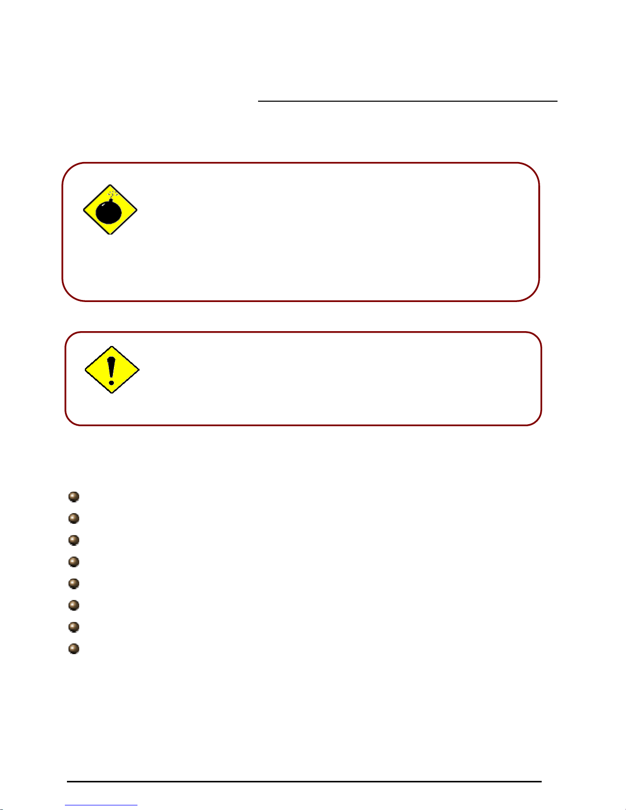
The Front LEDs
LED Meaning
1 PWR Lit when power is ON.
2 SYS Lit when the system is ready.
3 - 5
LAN Port
1X — 3X
(RJ-45 connector)
Lit when connected to an Ethernet device.
Green for 100Mbps; Orange for 10Mbps.
Blinking when data is Transmitted / Received.
7
WLAN
(Wireless Router only)
Lit green when the wireless connection is established.
Flashes when sending/receiving data.
8 – 9
Phone
1X — 2X
(RJ-11 connector)
Lit green when the phone is off-hook.
10
LINE
(Wireless Router with LINE port
only)
Lit when the inbound and outbound calls transmitted
through PSTN.
11
VoIP
Lit when SIP registration is OK.
12 PPP / MAIL
Lit steady when there is a PPPoA / PPPoE connection.
Lit and flashed periodically when there is email in the
Inbox.
13 ADSL
Lit when successfully connected to an ADSL DSLAM
(“linesync”).
7
VoIP/(802.11g) ADSL2+ Router
Chapter 2: Installing the router
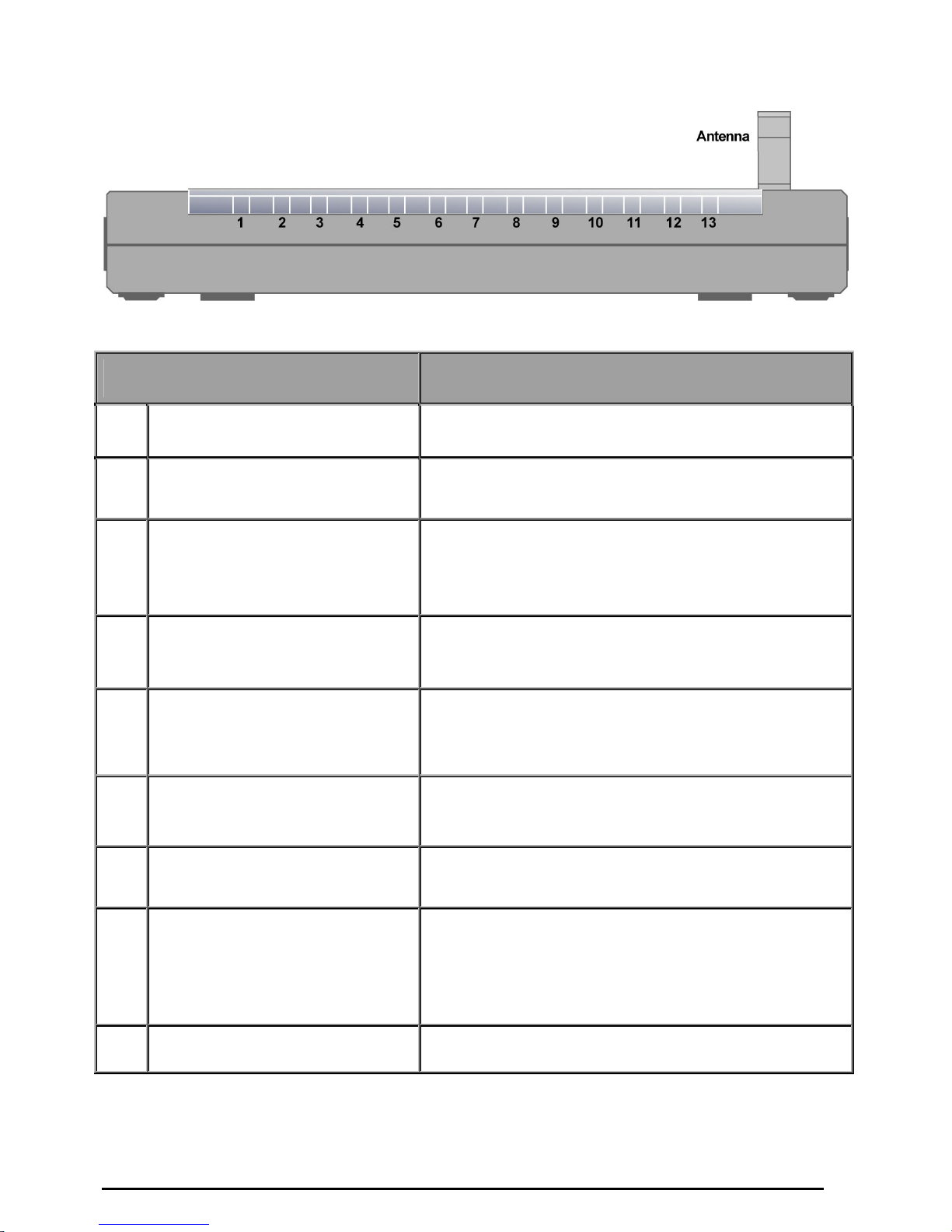
The Rear Ports
VoIP ADSL Router
VoIP/802.11g ADSL Router
VoIP/802.11g ADSL Router with LINE port
1
3
2
4
3
5
6
3
5
6
7
1
2
4
1
2
4
5
6
7 8
9
7
8
8
VoIP/(802.11g) ADSL2+ Router
Chapter 2: Installing the router
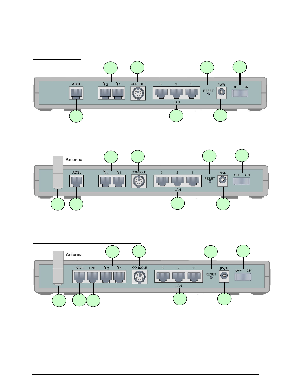
Port Meaning
1
Power Switch
Power ON/OFF switch
2
PWR
Connect the supplied power adapter to this jack.
3 RESET
After the device is powered on, press it to reset the device or
restore to factory default settings.
0-3 seconds: reset the device
6 seconds above: restore to factory default settings (this is
used when you can not login to the router, e.g. forgot the
password)
4
LAN
1X — 3X
(RJ-45 connector)
Connect a UTP Ethernet cable (Cat-5 or Cat-5e) to one of the
four LAN ports when connecting to a PC or an office/home
network of 10Mbps or 100Mbps.
5
CONSOLE
Connect a PS2/RS-232 cable to this port when connecting to a
PC’s RS-232 port (9-pin serial port).
6
Phone
1X ─ 2X
(RJ-11 connector)
Connect RJ-11 cable to this port when connecting to an analog
phone set.
7
ADSL
Connect the supplied RJ-11 (“telephone”) cable to this port when
connecting to the ADSL/telephone network.
8
Antenna
(Wireless Router only)
Connect the detachable antenna to this port.
9
LINE
(Wireless Router with LINE
port only)
Connect RJ-11 cable to this port when connecting to the
telephone wall jack.
9

VoIP/(802.11g) ADSL2+ Router
Chapter 2: Installing the router
Cabling
One of the most common causes of problems is bad cabling or ADSL line(s). Make sure that all
connected devices are turned on. On the front of the product is a bank of LEDs. Verify that the LAN Link
and ADSL line LEDs are lit. If they are not, verify that you are using the proper cables.
Ensure that all other devices connected to the same telephone line as your router (e.g. telephones, fax
machines, analogue modems) have a line filter connected between them and the wall socket (unless
you are using a Central Splitter or Central Filter installed by a qualified and licensed electrician), and
ensure that all line filters are correctly installed and the right way around. Missing line filters or line filters
installed the wrong way around can cause problems with your ADSL connection, including causing
frequent disconnections.
10

VoIP/(802.11g) ADSL2+ Router
Chapter 3: Basic Installation
11
Chapter 3: Basic Installation
The router can be configured with your web browser. A web browser is included as a standard
application in the following operating systems: Linux, Mac OS, Windows 98/NT/2000/XP/Me, etc. The
product provides a very easy and user-friendly interface for configuration.
PCs must have an Ethernet interface installed properly and be connected to the router either directly or
through an external repeater hub, and have TCP/IP installed and configured to obtain an IP address
through a DHCP server or a fixed IP address that must be in the same subnet as the router. The default
IP address of the router is 192.168.1.254 and the subnet mask is 255.255.255.0 (i.e. any attached PC
must be in the same subnet, and have an IP address in the range of 192.168.1.1 to 192.168.1.253). The
best and easiest way is to configure the PC to get an IP address automatically from the router using
DHCP. If you encounter any problems accessing the router’s web interface it may also be advisable to
uninstall any kind of software firewall on your PCs, as they can cause problems accessing the
192.168.1.254 IP address of the router. Users should make their own decisions on how to best protect
their network.
Please follow the steps below for your PC’s network environment installation. First of all, please check
your PC’s network components. The TCP/IP protocol stack and Ethernet network adapter must be
installed. If not, please refer to your Windows-related or other operating system
manuals.
Any TCP/IP capable workstation can be used to communicate with or through the
router. To configure other types of workstations, please consult the manufacturer’s
documentation.
VoIP/(802.11g) ADSL2+ Router
Chapter 3: Basic Installation
12
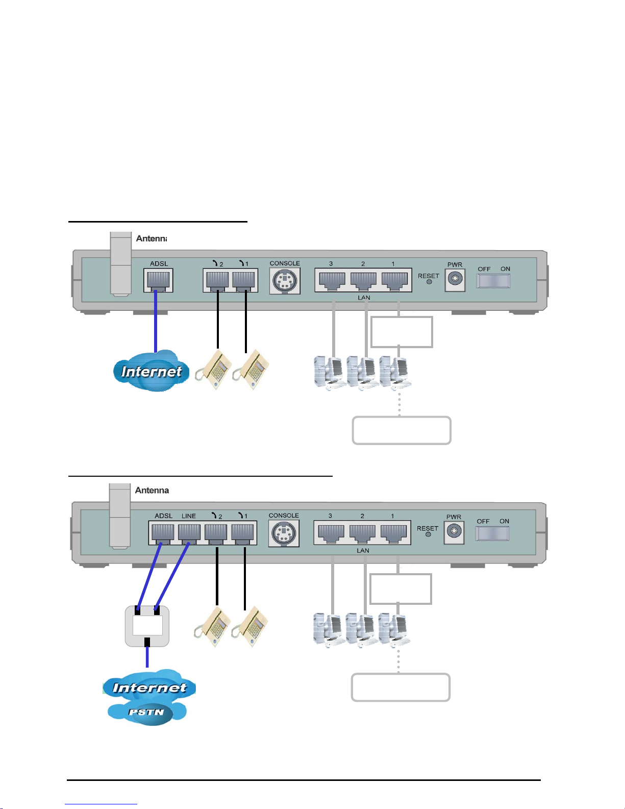
Connecting your router
1. Connect this router to a LAN (Local Area Network) and the ADSL/telephone (ADSL) network.
2. Power on the device.
3. Make sure the PWR and SYS LEDs are lit steadily and that the LAN LED is lit.
4. Connect an RJ11 cable to VoIP port when connecting to an analog phone set.
5. Connect RJ-11 cable to LINE Port when connecting to the telephone wall jack (Wireless Router
with LINE port only).
VoIP/(802.11g) ADSL Router
Analog Phone
Switching/
HUB
(Wireless Router only)
Connect more
computers
VoIP/802.11g ADSL Router with LINE port
Analog Phone
ADSL
Splitte
r
ADSL Phone
Line
Connect more
computers
Switching/
HUB
VoIP/(802.11g) ADSL2+ Router
Chapter 3: Basic Installation
13
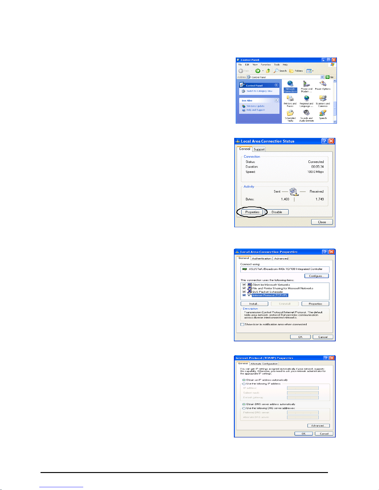
Configuring PCs in Windows in Window XP
1. Go to Start / Control Panel (in Classic View). In the Control
Panel, double-click Network Connections.
2. Double-click Local Area Connection. (See Figure 3.1)
3. In the LAN Area Connection Status window, click
Properties. (See Figure 3.2)
4. Select Internet Protocol (TCP/IP) and click Properties.
(See Figure 3.3)
5. Select the Obtain an IP address automatically and Obtain
DNS server address automatically radio buttons. (See
Figure 3.4)
6. Click OK to finish the configuration.
Figure 3.1: LAN Area Connection
Figure 3.2: LAN Connection
Status
Figure 3.3: TCP / IP
Figure 3.4: IP Address & DNS
Configuration
VoIP/(802.11g) ADSL2+ Router
Chapter 3: Basic Installation
14
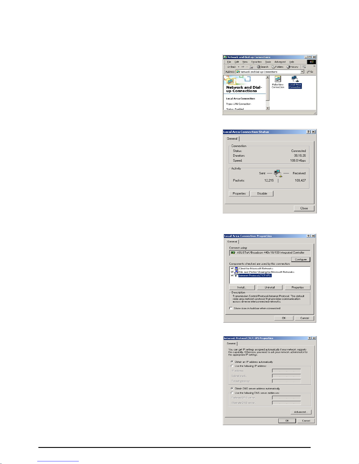
Configuring PCs in Windows 2000
1. Go to Start / Settings / Control Panel. In the Control Panel,
double-click Network and Dial-up Connections.
2. Double-click Local Area (“LAN”) Connection. (See Figure
3.5)
3. In the LAN Area Connection Status window, click
Properties. (See Figure 3.6)
4. Select Internet Protocol (TCP/IP) and click Properties.
(See Figure 3.7)
5. Select the Obtain an IP address automatically and Obtain
DNS server address automatically radio buttons. (See
Figure 3.8)
6. Click OK to finish the configuration.
Figure 3.5: LAN Area Connection
Figure 3.6: LAN Connection
Status
Figure 3.7: TCP / IP
Figure 3.8: IP Address & DNS
Configuration
VoIP/(802.11g) ADSL2+ Router
Chapter 3: Basic Installation
15
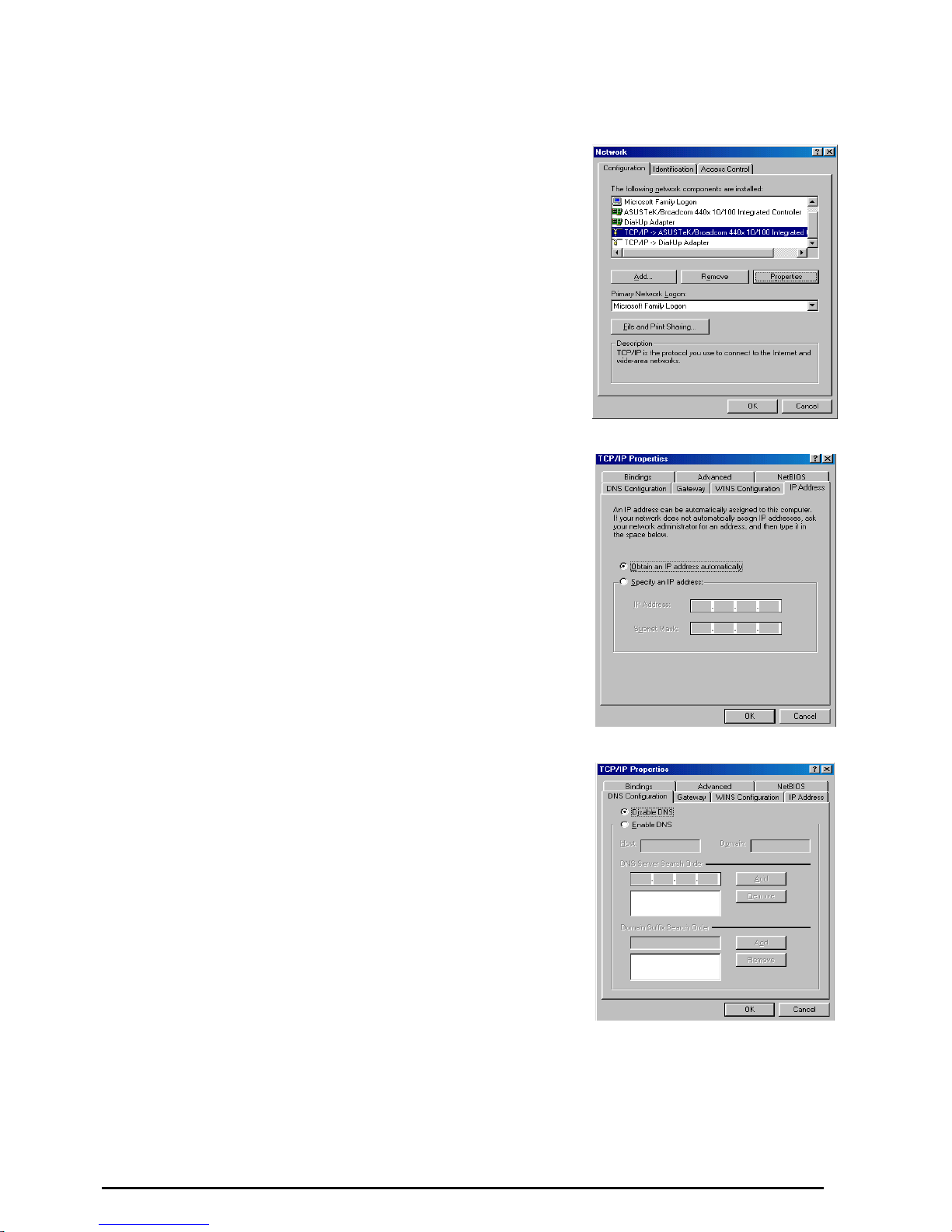
Configuring PC in Windows 95/98/ME
1. Go to Start / Settings / Control Panel. In the Control Panel,
double-click Network and choose the Configuration tab.
2. Select TCP / IP -> NE2000 Compatible, or the name of any
Network Interface Card (NIC) in your PC. (See Figure 3.9)
3. Click Properties.
4. Select the IP Address tab. In this page, click the Obtain an
IP address automatically radio button. (See Figure 3.10)
5. Then select the DNS Configuration tab. (See Figure 3.11)
6. Select the Disable DNS radio button and click OK to finish
the configuration.
Figure 3.9: TCP / IP
Figure 3.10: IP Address
Figure 3.11: DNS Configuration
VoIP/(802.11g) ADSL2+ Router
Chapter 3: Basic Installation
16
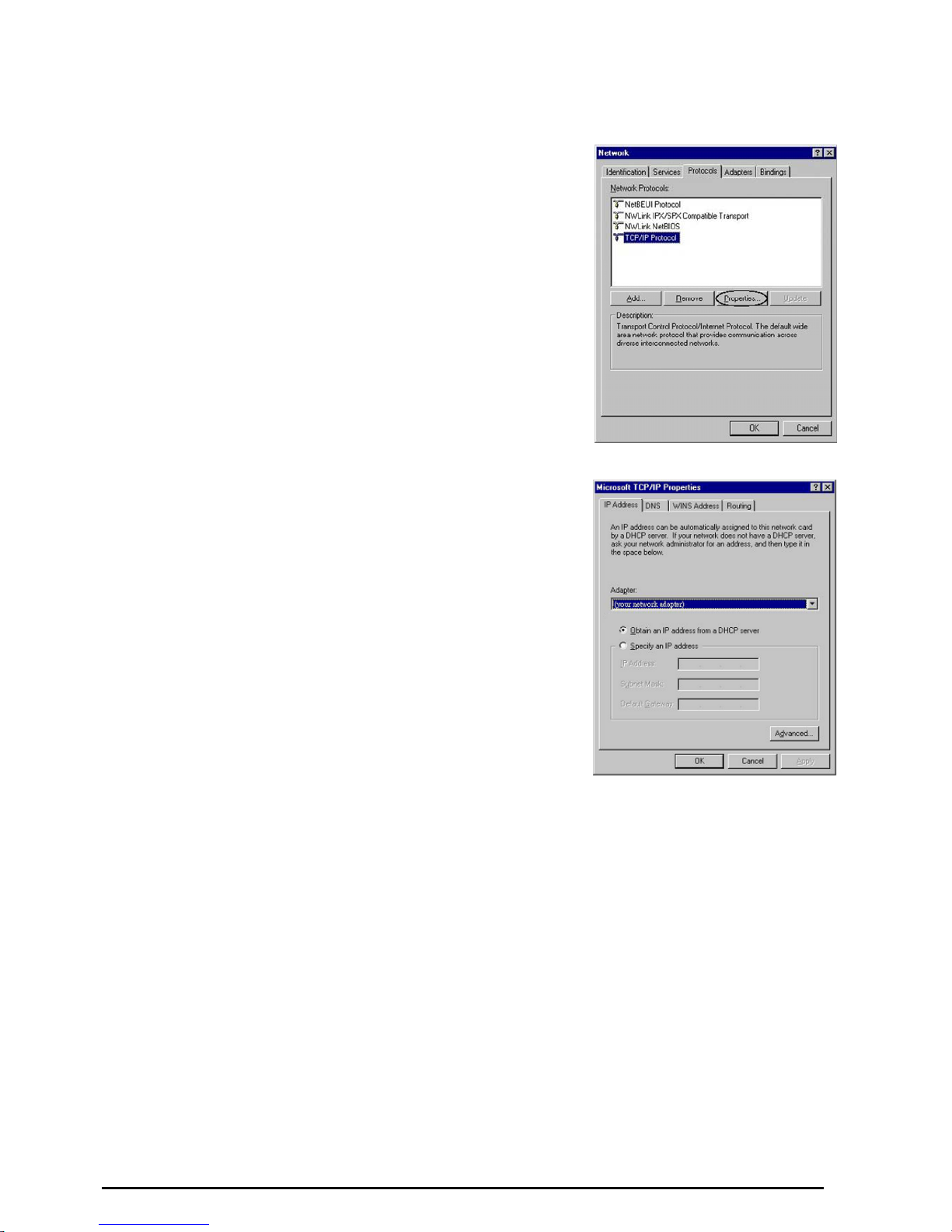
Configuring PC in Windows NT4.0
1.
Go to Start / Settings / Control Panel. In the Control
Panel, double-click Network and choose the Protocols tab.
2. Select TCP/IP Protocol and click Properties. (See Figure
3.12)
3. Select the Obtain an IP address from a DHCP server radio
button and click OK. (See Figure 3.13)
Figure 3.12: TCP / IP
Figure 3.13: IP Address
VoIP/(802.11g) ADSL2+ Router
Chapter 3: Basic Installation
17
Factory Default Settings
Before configuring your, you need to know the following default settings.
Web Interface (Username and Password)
Username: admin
Password: admin
The default username and password are “admin” and “admin” respectively.
A
ttention
A
ttention
If you ever forget the password to log in, you may press the RESET button up to
6 seconds to restore the factory default settings.
LAN Device IP Settings
IP Address: 192.168.1.254
Subnet Mask: 255.255.255.0
ISP setting in WAN site
PPPoE
DHCP server
DHCP server is enabled.
Start IP Address: 192.168.1.100
IP pool counts: 100
LAN and WAN Port Addresses
The parameters of LAN and WAN ports are pre-set in the factory. The default values are shown below.
LAN Port WAN Port
IP address
192.168.1.254
Subnet Mask
255.255.255.0
DHCP server function
Enabled
IP addresses for
distribution to PCs
100 IP addresses continuing from
192.168.1.100 through 192.168.1.199
The PPPoE function is enabled
to automatically get the WAN
port configuration from the ISP,
but you have to set the
username and password first.

VoIP/(802.11g) ADSL2+ Router
Chapter 3: Basic Installation
18
Information from your ISP
Before configuring this device, you have to check with your ISP (Internet Service Provider) what kind of
service is provided such as PPPoE, PPPoA, RFC1483, or IPoA.
Gather the information as illustrated in the following table and keep it for reference.
PPPoE VPI/VCI, VC-based/LLC-based multiplexing, Username, Password, Service
Name, and Domain Name System (DNS) IP address (it can be automatically
assigned by your ISP when you connect or be set manually).
PPPoA VPI/VCI, VC-based/LLC-based multiplexing, Username, Password, and
Domain Name System (DNS) IP address (it can be automatically assigned by
your ISP when you connect or be set manually).
RFC1483 Bridged VPI/VCI, VC-based/LLC-based multiplexing to use Bridged Mode.
RFC1483 Routed VPI/VCI, VC-based/LLC-based multiplexing, IP address, Subnet mask,
Gateway address, and Domain Name System (DNS) IP address (it is fixed IP
address).
IPoA VPI/VCI, VC-based/LLC-based multiplexing, IP address, Subnet mask,
Gateway address, and Domain Name System (DNS) IP address (it is fixed IP
address).
VoIP/(802.11g) ADSL2+ Router
Chapter 3: Basic Installation
19
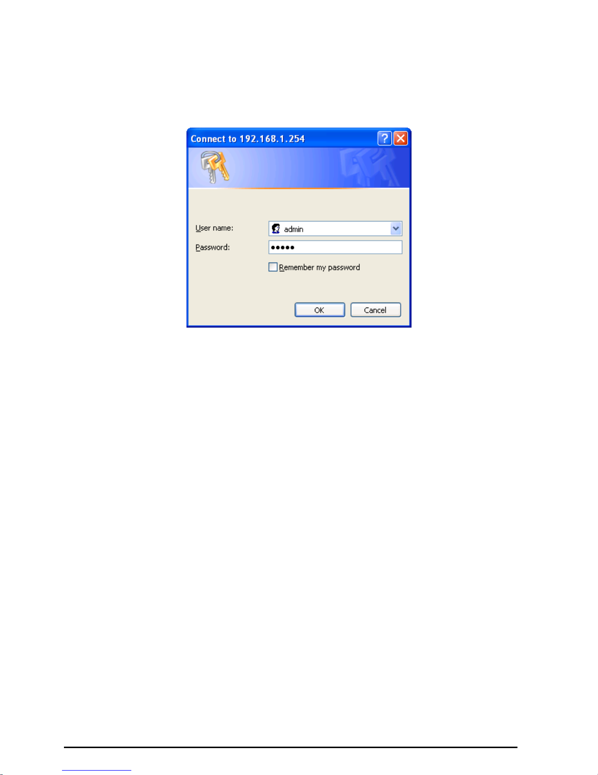
Configuring with your Web Browser
Open your web browser, enter the IP address of your router, which by default is 192.168.1.254, and click
“Go”, a user name and password window prompt will appear. The default username and password
are “admin” and “admin”. (See Figure 3.14)
Figure 3.14: User name & Password Prompt Widonw
Congratulation! You are now successfully logon to the VoIP ADSL Router!

VoIP/(802.11g) ADSL2+ Router
Chapter 4: Configuration
Chapter 4: Configuration
At the configuration homepage, the left navigation pane where bookmarks are provided links you directly
to the desired setup page, including:
Status (ARP Table, Wireless Association Table, Routing Table, DHCP Table, Email Status, VoIP
Status, Event Log, Error Log, NAT Sessions and UPnP Portmap)
Quick Start
Configuration
(LAN, WAN, System, Firewall, VoIP, QoS, Virtual Server, Time Schedule and Advanced)
Save Config to FLASH
Language (provides user interface in English and Deutsch languages)
Please see the relevant sections of this manual for detailed instructions on how to configure the VoIP
ADSL Router.
20
VoIP/(802.11g) ADSL2+ Router
Chapter 4: Configuration
Status
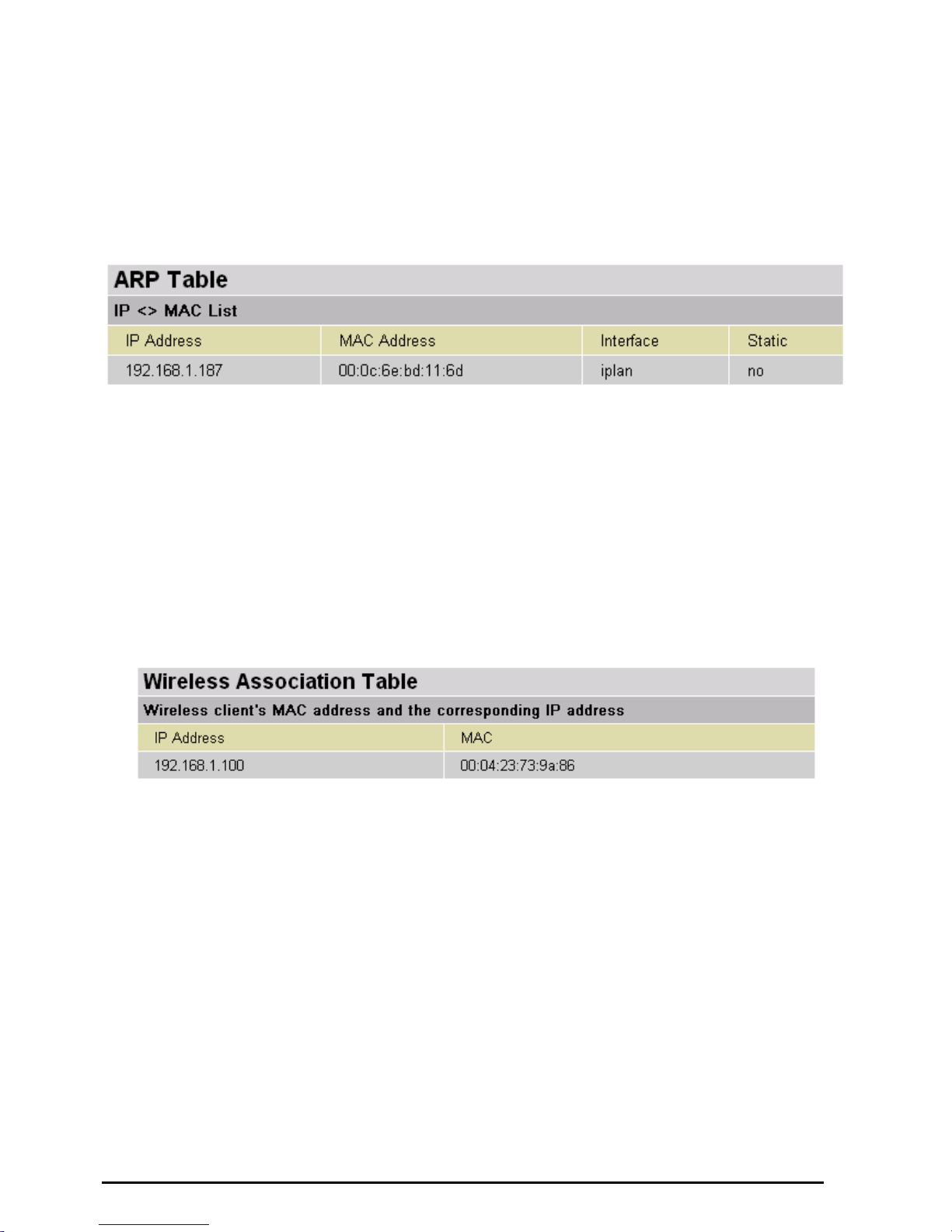
ARP Table
This section displays the router’s ARP (Address Resolution Protocol) Table, which shows the mapping
of Internet (IP) addresses to Ethernet (MAC) addresses. This is useful as a quick way of determining the
MAC address of the network interface of your PCs to use with the router’s Firewall – MAC Address
Filter function. See the Firewall section of this manual for more information on this feature.
IP Address: A list of IP addresses of devices on your LAN (Local Area Network).
MAC Address: The MAC (Media Access Control) addresses for each device on your LAN.
Interface: The interface name (on the router) that this IP Address connects to.
Static: Static status of the ARP table entry:
“no” for dynamically-generated ARP table entries
“yes” for static ARP table entries added by the user
Wireless Association Table
(Wireless Router only)
IP Address: It is IP address of wireless client that joins this network.
MAC: The MAC address of wireless client.
21
VoIP/(802.11g) ADSL2+ Router
Chapter 4: Configuration
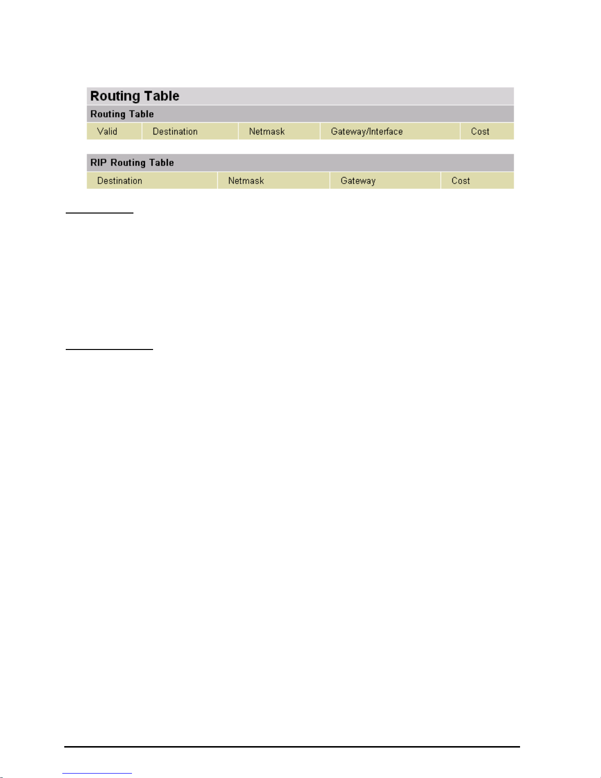
Routing Table
Routing Table
Valid: It indicates a successful routing status.
Destination: The IP address of the destination network.
Netmask: The destination netmask address.
Gateway/Interface: The IP address of the gateway or existing interface that this route will use.
Cost: The number of hops counted as the cost of the route.
RIP Routing Table
Destination: The IP address of the destination network.
Netmask: The destination netmask address.
Gateway: The IP address of the gateway that this route will use.
Cost: The number of hops counted as the cost of the route.
22
VoIP/(802.11g) ADSL2+ Router
Chapter 4: Configuration
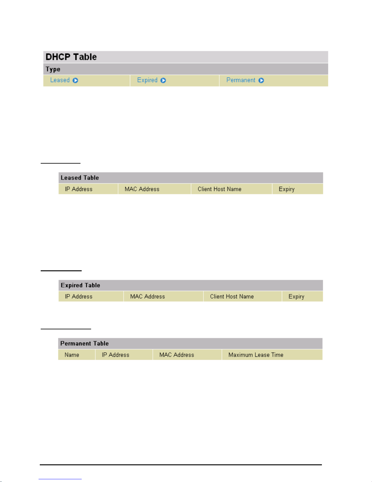
DHCP Table
Leased: The DHCP assigned IP addresses information.
IP Address: A list of IP addresses of devices on your LAN (Local Area Network).
Expired: The expired IP addresses information.
Permanent: The fixed host mapping information
Leased Table
IP Address: The IP address that assigned to client.
MAC Address: The MAC address of client.
Client Host Name: The Host Name (Computer Name) of client.
Expiry: The current lease time of client.
Expired Table
Please refer the Leased Table.
Permanent Table
Name: The name you assigned to the Permanent configuration.
IP Address: The fixed IP address for the specify client.
MAC Address: The MAC Address that you want to assign the fixed IP address
Maximum Lease Time: The maximum lease time interval you allow to clients
23
VoIP/(802.11g) ADSL2+ Router
Chapter 4: Configuration
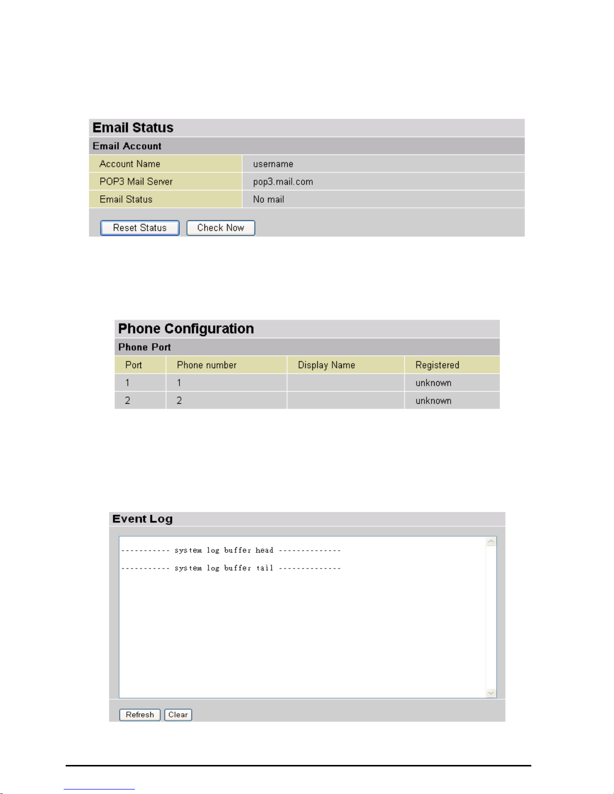
Email Status
Details and status for the Email Account you have configured the router to check. Please see the
Advanced section of this manual for details on this function.
VoIP Status
Details and status for the VoIP Account you have configured the router to check. Please see the Phone
Configuration section of this manual for details on this function.
Event Log
This page displays the router’s Event Log entries. Major events are logged to this window, such as when
the router’s ADSL connection is disconnected, as well as Firewall events when you have enabled
Intrusion or Blocking Logging in the Configuration – Firewall section of the interface. Please see the
Firewall section of this manual for more details on how to enable Firewall logging.
24
VoIP/(802.11g) ADSL2+ Router
Chapter 4: Configuration
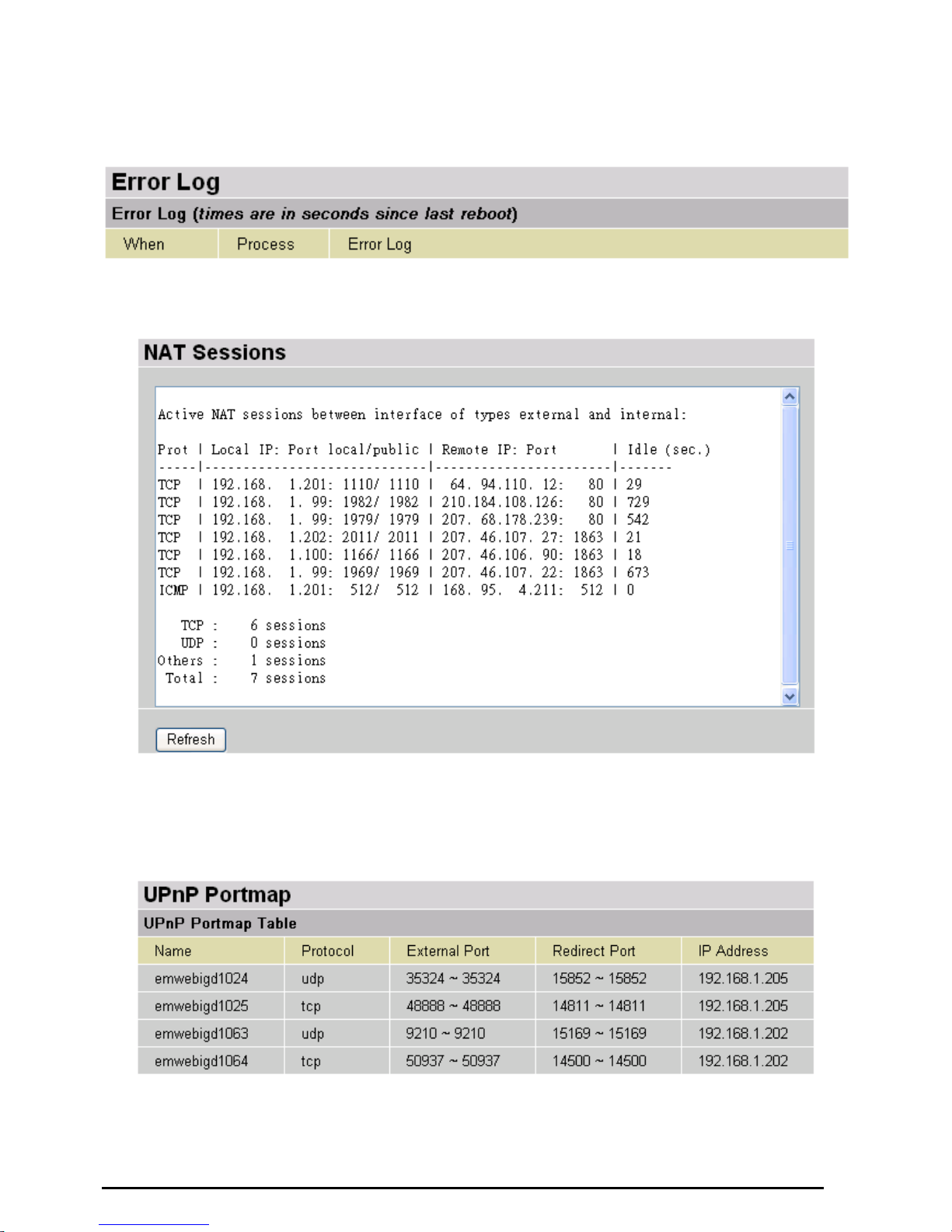
Error Log
Any errors encountered by the router (e.g. invalid names given to entries) are logged to this window.
NAT Sessions
This section lists all current NAT sessions between interface of types external (WAN) and internal (LAN).
UPnP Portmap
The section lists all port-mapping established using UPnP (Universal Plug and Play). Please see the
Advanced section of this manual for more details on UPnP and the router’s UPnP configuration options.
25
VoIP/(802.11g) ADSL2+ Router
Chapter 4: Configuration
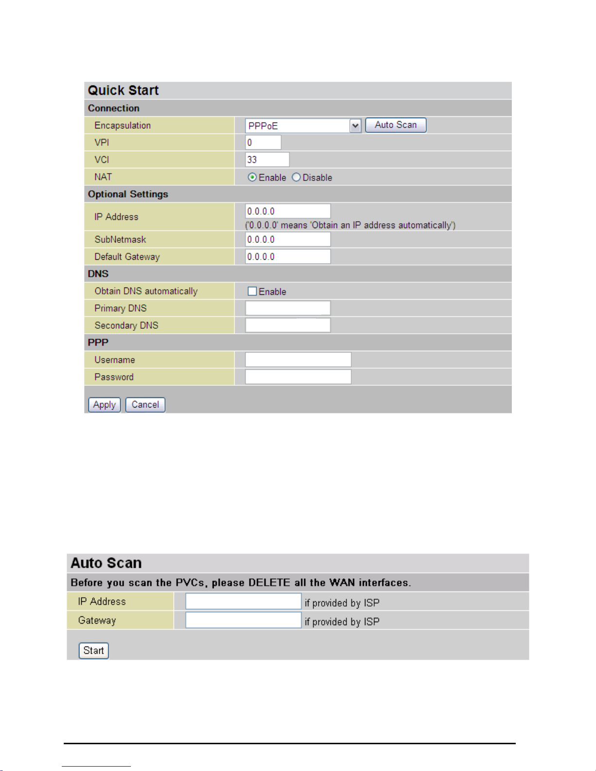
Quick Start
For detailed instructions on configuring your WAN settings, please see the WAN section of this manual.
Usually, the only details you will need for the Quick Start wizard to get you online are your login (often in
the form of username@ispname), your password and the encapsulation type. In additional, you have
the option to provide specific DNS as your desire, or check the Enable box to get the DNS automatically
from your ISP.
Your ISP will be able to supply all the details you need, alternatively, if you have deleted the current
WAN Connection in the WAN – ISP section of the interface, you can use the router’s PVC Scan feature
to attempt to determine the Encapsulation types offered by your ISP.
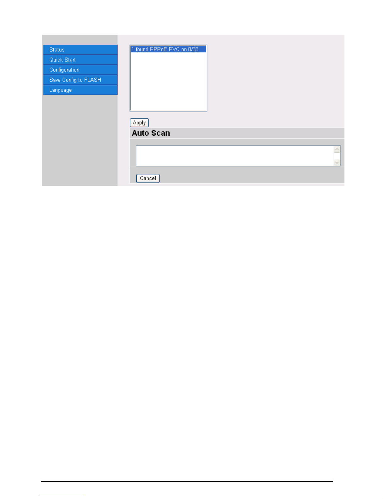
Click Start to begin scanning for encapsulation types offered by your ISP. If the scan is successful you
will then be presented with a list of supported options:
26
VoIP/(802.11g) ADSL2+ Router
Chapter 4: Configuration
Select the desired option from the list and click Apply to return to the Quick Start interface to continue
configuring your ISP connection. Please note that the contents of this list will vary, depending on what is
supported by your ISP.
27
VoIP/(802.11g) ADSL2+ Router
Chapter 4: Configuration
Configuration
When you click this item, you get following sub-items to configure the ADSL router.
LAN, WAN, System, Firewall, VoIP, QoS, Virtual Server, Time Schedule and Advanced
These functions are described below in the following sections.
There are seven items within the LAN section: Bridge Interface, Ethernet, Ethernet Client Filter,
Wireless, Wireless Security, Wireless Client Filter, Port Setting and DHCP Server.
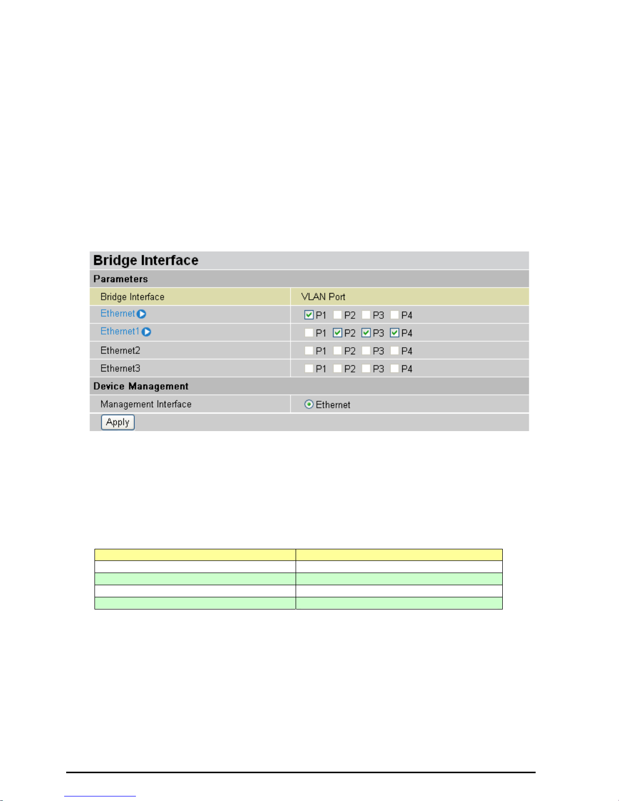
Bridge Interface
You can setup member ports for each VLAN group under Bridge Interface section. From the
example, two VLAN groups need to be created.
Ethernet: P1 (Port 1)
Ethernet1: P2, P3 and P4 (Port 2, 3, 4) Please uncheck P2, P3, P4 from Ethernet VLAN port first.
Note: You should setup each VLAN group with caution. Each Bridge Interface is arranged in
this order.
Bridge Interface VLAN Port (Always starts with)
Ethernet P1 / P2 / P3 / P4
Ethernet1 P2 / P3 / P4
Ethernet2 P3 / P4
Ethernet3 P4
Management Interface: To specify which VLAN group has possibility to do device
management, like doing web management.
Note: NAT/NAPT can be applied to management interface only.
28
VoIP/(802.11g) ADSL2+ Router
Chapter 4: Configuration
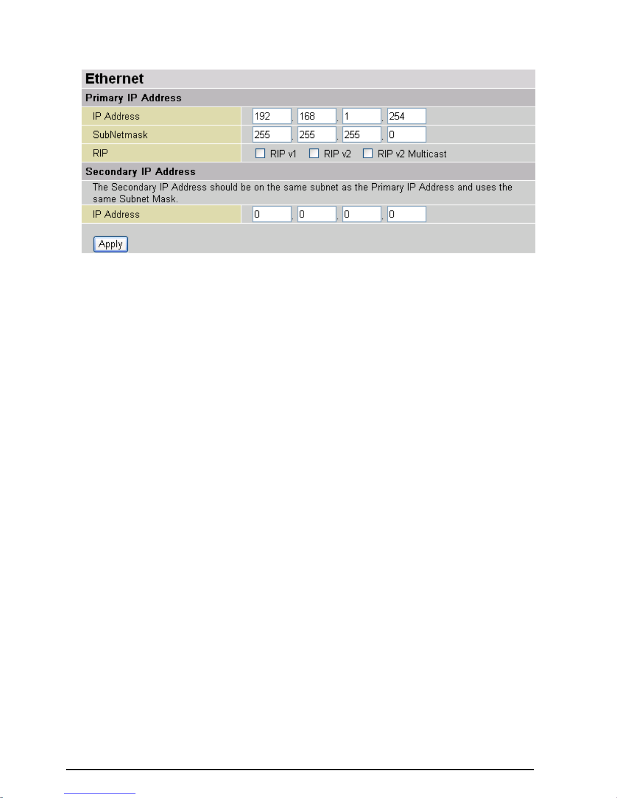
Ethernet
The router supports two Ethernet IP addresses in the LAN, and two different LAN subnets through
which you can access the Internet at the same time. Users usually only have one subnet in their
LAN, so there is no need to configure a Secondary IP address. The default IP address for the
router is 192.168.1.254.
RIP: RIP v1, RIP v2, and RIP v2 Multicast. Check to enable RIP function.
29
 Loading...