


TesiraFORTÉ
Fixed I/O
Server Devices
Operation Manual
April 2014
Biamp Systems, 9300 SW Gemini Drive, Beaverton, Oregon 97008 U.S.A. (503) 641-7287 www.biamp.com

TABLE OF CONTENTS
TesiraFORTÉ. . . . . . . . . . . . . . . . . . . . . . . . . . . . . . . . . . . . . . . . . |
. . . . . . . . . . . . . . . . . . . . . . .4 |
BENEFITS . . . . . . . . . . . . . . . . . . . . . . . . . . . . . . . . . . . . . . . . . . . . . . . . . . . . |
. . . . . . . . . . . . . . . . . . . . . . . . . . .4 |
COMMON FEATURES.. . . . . . . . . . . . . . . . . . . . . . . . . . . . . . . . . . . . . . . . . . . . . . . . |
. . . . . . . . . . . . . . . . . . . . . 5 |
AVB AI AND AI.. . . . . . . . . . . . . . . . . . . . . . . . . . . . . . . . . . . . . . . . . . . . . . . . . . . . . . . |
. . . . . . . . . . . . . . . . . . . . 5 |
AVB CI AND CI. . . . . . . . . . . . . . . . . . . . . . . . . . . . . . . . . . . . . . . . . . . . . . . . . . . . . . . . . . . . . . . . . |
. . . . . . . . . . 5 |
AVB TI AND TI. . . . . . . . . . . . . . . . . . . . . . . . . . . . . . . . . . . . . . . . . . . . . . . . . |
. . . . . . . . . . . . . . . . . . . . . . . . . . .5 |
AVB VI AND VI.. . . . . . . . . . . . . . . . . . . . . . . . . . . . . . . . . . . . . . . . . . . . . . . . . . . |
. . . . . . . . . . . . . . . . . . . . . . . . 5 |
TesiraFORTÉ FRONT PANEL. . . . . . . . . . . . . . . . . . . . . . . . . . . . . . . . . . . . . . . . . . . . . . . . . . .6 |
|
VENTILATION . . . . . . . . . . . . . . . . . . . . . . . . . . . . . . . . . . . . . . . . . . . . . . . . . |
. . . . . . . . . . . . . . . . . . . . . . . . . . .6 |
DISPLAY NAVIGATION BUTTONS. . . . . . . . . . . . . . . . . . . . . . . . . . . . . . . . . |
. . . . . . . . . . . . . . . . . . . . . . . . . . .6 |
LED STATUS INDICATORS. . . . . . . . . . . . . . . . . . . . . . . . . . . . . . . . . . . . . . . . . . . . . . . . . |
. . . . . . . . . . . . . . . . 6 |
OLED DISPLAY. . . . . . . . . . . . . . . . . . . . . . . . . . . . . . . . . . . . . . . . . . . . . . . . |
. . . . . . . . . . . . . . . . . . . . . . . . . . .7 |
Home Screen. . . . . . . . . . . . . . . . . . . . . . . . . . . . . . . . . . . . . . . . . . . . . . . . |
. . . . . . . . . . . . . . . . . . . . . . . . . . .7 |
Menu Screen . . . . . . . . . . . . . . . . . . . . . . . . . . . . . . . . . . . . . . . . . . . . . . . . |
. . . . . . . . . . . . . . . . . . . . . . . . . . .7 |
Faults . . . . . . . . . . . . . . . . . . . . . . . . . . . . . . . . . . . . . . . . . . . . . . . . . . . . . . |
. . . . . . . . . . . . . . . . . . . . . . . . . . .8 |
Edit Timeouts . . . . . . . . . . . . . . . . . . . . . . . . . . . . . . . . . . . . . . . . . . . . . . . . |
. . . . . . . . . . . . . . . . . . . . . . . . . . .8 |
Localization. . . . . . . . . . . . . . . . . . . . . . . . . . . . . . . . . . . . . . . . . . . . . . . . . . . . . . . . . . . . . . . . . . . . . . . . . |
. . . 8 |
TesiraFORTÉ AVB AI REAR PANEL.. . . . . . . . . . . . . . . . . . . . . . . . . . |
. . . . . . . . . . . . . . . . . . . 9 |
QUICK START . . . . . . . . . . . . . . . . . . . . . . . . . . . . . . . . . . . . . . . . |
. . . . . . . . . . . . . . . . . . . . . .10 |
PREREQUISITES. . . . . . . . . . . . . . . . . . . . . . . . . . . . . . . . . . . . . . . . . . . . . . . . . . . . . . . . . . . . . . |
. . . . . . . . . . 10 |
CONNECTING TO THE TESIRAFORTÉ SYSTEM. . . . . . . . . . . . . . . . . . . . . |
. . . . . . . . . . . . . . . . . . . . . . . . . .10 |
SETTING AN IP ADDRESS. . . . . . . . . . . . . . . . . . . . . . . . . . . . . . . . . . . . . . . |
. . . . . . . . . . . . . . . . . . . . . . . . . . 11 |
Assigning an IP Address to your computer. . . . . . . . . . . . . . . . . . . . . . . . . . . . . . . . . . . . |
. . . . . . . . . . . . . . . 11 |
Auto assignment of IP Address using DHCP. . . . . . . . . . . . . . . . . . . . . . . . |
. . . . . . . . . . . . . . . . . . . . . . . . . .12 |
SPECIFICATIONS. . . . . . . . . . . . . . . . . . . . . . . . . . . . . . . . . . . . . . . . . . . . . . . . . . . . . . . . . . . |
13 |
WARRANTY. . . . . . . . . . . . . . . . . . . . . . . . . . . . . . . . . . . . . . . . . . |
. . . . . . . . . . . . . . . . . . . . . .15 |
COMPLIANCE . . . . . . . . . . . . . . . . . . . . . . . . . . . . . . . . . . . . . . . . |
. . . . . . . . . . . . . . . . . . . . . .16 |
EC DECLARATION OF CONFORMITY.. . . . . . . . . . . . . . . . . . . . . |
. . . . . . . . . . . . . . . . . . . . . 18 |
ROHS COMPLIANCE AND HAZARDOUS SUBSTANCE TABLE |
. . . . . . . . . . . . . . . . . . . . . .19 |
2
|
IMPORTANT SAFETY INSTRUCTIONS |
||
|
|
|
|
|
|
|
|
1) |
Read these instructions.. |
11) Only use attachments/accessories specified by the |
|
2) |
Keep these instructions.. |
manufacturer.. |
|
3) |
Heed all warnings. |
12) Use only with equipment rack, |
|
4) |
Follow all instructions.. |
cart, stand or table designed to provide |
|
adequate mechanical strength, heat |
|||
5) |
Do not use this product near water.. |
||
dissipation and securement to the |
|||
6) |
Clean only with dry cloth. |
||
building structure.. |
|||
7) |
Do not block ventilation openings.. Install in |
||
When a cart is used, use caution when moving the cart |
|||
accordance with the manufacturer’s instructions.. |
|||
and product combination to avoid injury from tip-over.. |
|||
8) |
Do not install near any heat sources such as |
||
13) Unplug this product during lightning storms or when |
|||
radiators, heat registers, stoves, or other products |
|||
unused for long periods of time.. |
|||
(including amplifiers) that produce heat. |
|||
14) Refer all servicing to qualified service personnel. |
|||
9) |
Do not defeat the safety purpose of the grounding- |
||
Servicing is required when the product has been |
|||
type plug.. A grounding type plug has two blades and a |
|||
damaged in any way, such as power-supply cord or |
|||
third grounding prong.. |
|||
plug is damaged, liquid has been spilled or objects have |
|||
The third prong is provided for your safety.. If the |
|||
fallen into the product, the product has been exposed to |
|||
provided plug does not fit into your outlet, consult an |
rain or moisture, does not operate normally, or has been |
||
electrician for replacement of the obsolete outlet.. |
dropped.. |
||
10) |
Protect the power cord from being walked on or |
|
|
pinched, particularly at plugs, convenience receptacles |
|
||
and the point where they exit from the product.. |
|
||
|
|
||
Explanation of Graphical Symbols: |
|
||
|
Lightning Bolt: Hazardous Live voltages present when this unit is in operation.. Do not touch terminals marked with |
||
|
this symbol while the unit is connected to live power.. |
|
|
Exclamation Point: Replace components (i.e. fuses) only with the values specified by the manufacturer. Failure to do so will compromise safe operation of this unit
Hazardous Moving Fan Blades: Remove power before servicing and keep away from moving fan blades..
WARNING - To reduce the risk of fire or electric shock, do not expose these products to rain or moisture. These products must not be exposed to dripping or splashing and no objects filled with liquids, such as vases, shall be placed on these products.
WARNING – 100 Volt Speaker terminals marked with the symbol  are Hazardous Live.. External wiring connected to these terminals requires installation by a Skilled or Instructed Person.
WARNING – MAINS Powered Products employ Safety Grounding and must be connected to a MAINS socket that is properly grounded to provide a protective earthing connection..
Disconnect Device - The MAINS plug is used to disconnect MAINS power and must remain readily operable..
CAUTION – When POTS Telephone Interface options are provided, connections to the telecom circuits of this device must be made by qualified, trained personnel. To reduce the risk of fire, use only No. 26 AWG solid copper wire for telecom circuit connections..
Intended for Installation and Service by Skilled Personnel Only:
CAUTION – To reduce the Risk of Electric Shock, Installation and Service of Biamp Products should be conducted only by Skilled Persons who are Biamp Qualified Audio Installation Professionals.
Do not perform any servicing other than that contained in the Operating Instructions unless you are a Skilled Person qualified to do so..
Skilled Persons must disconnect AC MAINS Power before opening product..
CAUTION - The Installation steps for ‘Auxiliary Power’ are for use by Skilled Personnel only and must comply with all local codes..
•National Electrical Code, ANSI/NFPA 70 for United States.
•Canadian Electrical Code, Part 1, CSA C22.1, Sections 2-128, 12-010(3) and 12-100 for Canada.
Wall Mounting Instructions – Wall mounted products must be securely fastened to drywall or similar surface using a minimum of 4 wood screws (2 screws for product with only two mounting holes).. Alternate fasteners which may be used include drywall anchors, self-tapping sheet metal screws located in metal studs or wood screws extending a minimum of ½ inch into wood studs..
3

TesiraFORTÉ FIXED I/O SERVER DEVICES
The TesiraFORTÉ products are server-class devices that are designed to operate as standalone processing devices, with Tesira expanders and controllers, or as part of a full set of Tesira devices. All TesiraFORTÉ models feature 12 analog mic/line level inputs and 8 analog mic/line level outputs in a fixed configuration.All models also include configurable USB audio, 4 GPIO connections, RS-232 serial port, Ethernet control port and an internal power supply with a standard IEC three-conductor removable power cord. The front panel of each TesiraFORTÉ server features an OLED display for system and unit information including device IP and MAC addresses. The display is navigated with capacitive touch buttons.
The TesiraFORTÉ line can be used as a standalone device or can be combined with other TesiraFORTÉ devices and Tesira servers, expanders and controllers.
The TesiraFORTÉ line is separated into AVB-equipped and non-AVB equipped devices. The four models with AVB (Audio Video Bridging) have an RJ-45 EthernetAVB connector for connecting with other Tesira audio devices through the use ofAVB switches. The TesiraFORTÉ servers have a capacity of 128 channels of audio in and 128 channels of audio out over AVB.
The non-AVB TesiraFORTÉ servers have the same features and processing functionality as the AVB-equipped servers, but without the ability to make a digital audio connection to other Tesira audio devices.
Benefits
Allows integrators to choose which model works best for the installation environment.
•Application-specific models make system design, configuration, and installation easier and faster.
•Included default configuration file allows for plug-and-play usage.
•Highly scalable and cost-effective solution that can grow over time with the needs of the customer.
•SpeechSense™ technology enhances speech processing and system behavior.
•Sona™Acoustic Echo Cancellation (AEC) technology to enhance speech processing (CI, TI and VI models only).
•Integrates directly with soft codecs and other USB audio hosts with support for USBAudio Class 1.0.
4

TesiraFORTÉ FIXED I/O SERVER DEVICES
TesiraFORTÉ models are available in four application-optimized configurations. They share a number of common features:
Common Features
•128 x 128 channels of AVB (AVB models only)
•Gigabit Ethernet port
•Up to 8 channels of configurable USB audio
•RS-232 serial port
•4 General Purpose Inputs/Outputs (GPIO)
•OLED display with capacitive-touch navigation
•Rack-mountable (1RU)
•Internal universal power supply
AVB AI and AI
TesiraFORTÉAVBAI and TesiraFORTÉAI: Standard audio processing applications
•12 mic/line level inputs
•8 mic/line level outputs
AVB CI and CI
TesiraFORTÉAVB CI and TesiraFORTÉ CI: External codec conferencing applications
•12 mic/line level inputs with Sona™AEC on all inputs
•8 mic/line level outputs
AVB TI and TI
TesiraFORTÉAVB TI and TesiraFORTÉ TI: Telephone conferencing applications
•12 mic/line level inputs with Sona™AEC on all inputs
•8 mic/line level outputs
•Telephone interface (RJ-11 connector)
AVB VI and VI
TesiraFORTÉAVB VI and TesiraFORTÉ VI: Conferencing applications with Voice over IP (VoIP)
•12 mic/line level inputs with SonaAEC on all inputs
•8 mic/line level outputs
•VoIP interface (RJ-45 connector)
5
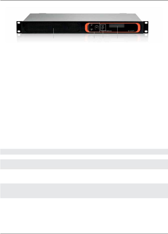
TesiraFORTÉ FIXED I/O SERVER DEVICES FRONT PANEL
|
1 |
2 |
3 |
4 |
|
|
TesiraFORTÉ AVB AI model shown |
|
|
||
1 – Ventilation fan cover |
2 – Display navigation buttons |
3 – LED status indicators |
4 – OLED display |
||
Ventilation
Each device has a perforated cover to allow cool air into the chassis.Avariable speed temperature controlled fan allows air into the front of the unit and out of the rear left side. Ensure that nothing obstructs the front or side of the unit.
Display Navigation Buttons
Capacitive-touch buttons allow navigation through the OLED display menu to view and configure device and networking information, as well as see system-wide faults. Navigating the display is accomplished by touch-sensitive UP and DOWN and SELECT buttons.
LED Status Indicators
Five multi-color LEDs on the front panel of the device provide information about the status of the device and the greater Tesira system.
•Power – Reports power of the host device and Front Panel Display.
•Status – Reports the status of host device.
•Activity – Reports the activity of host device within the greater system.
•Alarm – Reports abnormal conditions local to the host device.
•AIS (Alarm Indication Signal) – Reports abnormal conditions within the greater system.
LED |
Off |
Green |
Yellow |
Red |
Power |
Unit is not powered |
Unit is powered |
Not applicable |
Not applicable |
Alarm |
No fault is active in the |
Not applicable |
Minor fault is active in |
Major fault is active |
|
device |
|
the device |
in the device |
Activity |
Not applicable |
The host device is an |
Not applicable |
The host device is part |
|
|
active part of an active |
|
of an inactive system. |
|
|
system |
|
(Audio is stopped.) |
Status |
Not applicable |
Device has received its |
Device is ready and |
Device is not ready to |
|
|
configuration and is ready |
waiting to receive a |
receive its configuration |
|
|
to participate in the system |
configuration |
|
AIS |
No fault is active in any |
Not applicable |
Minor fault is active in |
Major fault is active in |
(Alarm In System) |
device in the system |
|
a device in the system |
a device in the system |
6

TesiraFORTÉ FIXED I/O SERVER DEVICES FRONT PANEL
OLED Display
The OLED display provides information about the server device as well as the Tesira system that is connected to the server.
The OLED display is read-only.
Home Screen
The home screen is the default screen that shows the overview of the device. If the text is too long to fit on the entire display, it will scroll to the left. Menus at the bottom allow other selections. By default the main menu icon will be selected.
Some menu icons double as status indicators. They change depending on the status of the device. The fault status icon only appears if there is an active fault in the system.
After a period of inactivity, the Front Panel Display will transition back to this home screen.
1. |
Device description |
1 |
3 |
|
|||
2. |
Host Name and IP address |
|
|||||
|
|
|
|
|
|
||
3. |
Main Menu |
|
|
|
|
4 |
|
|
|
|
|||||
|
|
|
|
|
|
||
4. |
Network Menu / Status |
|
|
|
|
|
|
2 |
|
|
|
|
|||
|
|
|
|
|
|
||
To open any of the menus, use the UP and DOWN buttons to highlight the menu icon desired, and press the SELECT button.
Menu Screen
A menu screen containing a list of items that is used to navigate to other menus is accessible from the home screen. On the right are icons that provide quick navigation to other screens. Pressing the select button on an item will transition to the screen that displays that information. A scroll indicator at the left shows if there is more information to show by scrolling down.
Device Information
The device information screen shows the following information:
•Device description
•Host name
•Serial number
•Firmware revision
System Information
The system information screen shows the following information:
•Device audio state (on/off)
•System description
Network Information
The network information screen shows the following information
•Host name
•IP address
•Subnet mask
•Gateway
7

TesiraFORTÉ FIXED I/O SERVER DEVICES FRONT PANEL
Settings
The setting operations include the following: -Change brightness
-Change timeouts
Faults
If a fault is present in the system an exclamation icon is shown on the lower right of the screen. Each unique fault in the system will be listed.
Edit Timeouts
Dim Mode
The display has a screensaver mode where it will dim the display brightness. Pressing any button will bring the screen back to the original brightness and respond to the control movement.
Sleep Mode
After the display timeout is reached the display will go blank. The device will still have power in this state even though the display appears blank.
Localization
All menus and error messages are displayed in English by default. Descriptive icons are used to avoid the need for messages in specific languages. Text entered (e.g. Device description) will be displayed in the language as entered in the software.
The following alphabets are supported:
•Latin-1 (ISO/IEC 8859-1) and Latin-2 (ISO/IEC 8859-2)
•Cyrillic (Russian alphabet only)
•Simplified Chinese
•Japanese – Hiragana, Katakana, Kanji
•Thai
8

TesiraFORTÉ AVB AI REAR PANEL
9 |
|
|
|
|
|
8 |
|
|
|
||||||
|
|
|
|
|
|
|
|
|
|
|
|
|
|
|
|
|
|
|
|
|
|
|
|
|
|
|
|
|
|
|
|
|
|
|
|
|
|
|
|
|
|
|
|
|
|
|
|
|
|
|
|
|
|
|
|
|
|
|
|
|
|
|
|
|
|
|
|
|
|
|
|
|
|
|
|
|
|
|
|
|
|
|
|
|
|
|
|
|
|
|
|
|
|
|
|
|
|
|
|
|
|
|
|
|
|
|
|
|
|
|
|
|
|
|
|
|
|
|
|
|
|
|
|
|
|
|
|
|
|
|
|
|
|
|
|
|
|
|
|
|
|
|
|
|
|
|
|
|
|
|
|
|
|
|
|
|
|
|
|
1 2 3
1.AC power inlet
2.Gigabit Ethernet control port (RJ-45)
3.AVB port (RJ-45) –AVB models only
4.RS-232 serial port
5.USB-B port
6.GPIO connections
4 |
5 |
6 |
7 |
TesiraFORTÉ AVB AI model shown
7.Mic/line level output balanced analog connections
8.Mic/line level input balanced analog connections. -- AVBAI andAI – Mic/Line
-- AVB CI, TI, VI and CI, TI, VI – Mic/Line with SonaAEC
9.Telephony port
-- AVBAI, CI andAI, CI – Not available
-- AVB TI and TI – 1 analog telephone line (RJ-11) -- AVB VI and VI – 2 VoIP telephone lines (RJ-45)
AC Power Inlet
IEC connector which will acceptAC mains voltage of 100-240VAC @50/60Hz.
Gigabit Ethernet Port
Used to configure the TesiraFORTÉ unit with Tesira and BiampCanvas™ software. Can also be used to receive third-party commands over IP.
AVB Port (AVB models only)
Can send and receive up to 128x128 audio channels to other Tesira audio devices.
RS-232 port
Can be used to receive third party controls or output command strings.
USB- B port
Can be used to connect to a PC or a computer that is USBAudio Class 1 compliant. Four connection methods are supported:
1.Connection to a software based codec where the Tesira device does make use ofAEC such as the TesiraFORTÉ CI, TI and VI.
2.Connection to a software based codec which does not use TesiraAEC functions – such as a TesiraFORTÉAI.
3.Line In/Out mode – where the channels of Line In and Line Out are installed in Microsoft Windows® but do not show up by default.
9

TesiraFORTÉ FIXED I/O SERVER DEVICES QUICK START
Prerequisites
Before getting started please
1.Install Tesira software on a Windows PC.
The software must be Tesira version 2.0 or later.
The most up to date version can be downloaded from the Biamp website here: http://www.biamp.com/products/tesira/downloads.aspx.
2.Minimum PC requirements:
a.Windows® 7 SP1 32-bit or 64-bit
b.1280 x 1024 screen resolution (recommended)
3.Cables required:
Connection to the device should be made using either a direct connection or connection via an Ethernet switch. -- Direct Connection - 1x Cat5E cable to connect from the PC to the TesiraFORTÉ Control Port
-- Via a Switch - 2x Cat5E cables and 1 Ethernet switch
Connecting to the TesiraFORTÉ system
1.Connect the PC and TesiraFORTÉ to the network.
Connect a Cat5E cable between your PC and the TesiraFORTÉ device.
-- Direct connection:Attach an Ethernet cable from the PC’s network card to the TesiraFORTÉ Ethernet port. The TesiraFORTÉ Ethernet port is autosensing so a straight or crossover cable can be used.
-- Connecting via Ethernet switch:Attach an Ethernet cable from the network card to a 100/1000 Base-T Ethernet switch. The TesiraFORTÉ Ethernet port is autosensing so a straight or crossover cable can be used.
2.Power up TesiraFORTÉ devices:
Connect the supplied power cord to a groundedAC mains voltage of 100-240VAC @50/60Hz. Connect the other end of the power cord to the power entrance located on the rear of the TesiraFORTÉ unit. Note the status of the front panel LED’s. Under normal conditions, the power,Activity and Status LEDS’s will remain green once power-up sequence has completed.
3.Assign an IP address to the PC.
The PC must have a unique IP address in the same subnet as the TesiraFORTÉ device.ATesiraFORTÉ device is configured from the factory with DHCP or Zero Conf (Link Local) address. If you wish to verify your PC network interface is set correctly, please review the Setting an IP address section.
4.Configure the software to use the correct Network Interface.
Tesira software should automatically discover the available network interfaces and enable them. If you wish to verify the network interfaces you are using, open the Tesira software and select Tools > Options > Application settings > Network > Device Discovery. Selecting Interfaces will list the available connections. These can be enabled or disabled individually. Confirm the expected Network interface is selected and IP addressing is in the correct range.
5.Connect to the network with Tesira software.
Open the Tesira software. Connect to the network by going to System > Network > Connect to System. The System Connect dialog will appear. Select the required device listed in the System List and press Connect to System.
The software will connect and allow real time user control. When the required changes have been made, disconnect the PC from the
Tesira system by going to System > Network > Disconnect from system.
10

TesiraFORTÉ FIXED I/O SERVER DEVICES QUICK START
Setting an IP address
It may be a requirement to configure your PC or TesiraFORTÉ IP address. Please review the following section.
Assigning your computer’s IP address
Go to Control Panel > Network and Sharing Center. Click on LocalArea Connection.
The LocalArea Connection Status Dialog will open. Select Properties.
The LocalArea Connection Properties Dialog will open. Double-Click Internet Protocol Version 4 (TCP/IPv4).
11
 Loading...