


NPS-1
Networked
Paging Station-1
Operation Manual
Biamp Systems | 9300 S.W. Gemini Drive | Beaverton, OR | 97008 | USA | +1.503.641.7287 | www.biamp.com

blank
4Sep07

TABLE OF CONTENTS
Front Panel Controls
Rear Panel Connectors
Setup
System Connections
Specifications & Block Diagram
Warranty
CE Declaration
Safety Information
pg. 2
pg. 3
pgs. 4 & 5
pgs. 6 & 7
pg. 8
pg. 9
pg. 10
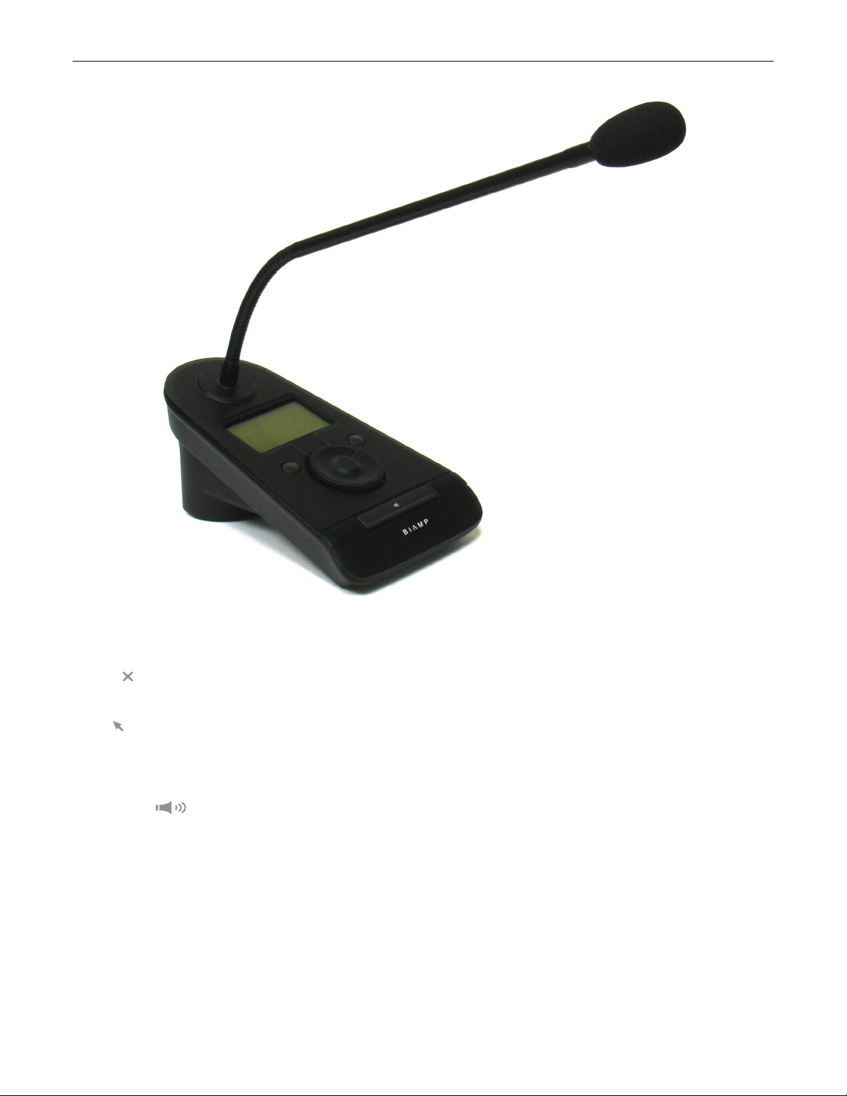
Paging Station
INTRODUCTION
Networked Paging Station-1 is a microphone console using a single cable to
carry audio, control, and power, with an innovative user-interface, designed
exclusively for use with AudiaFLEX systems. It provides a powerful and easyto-use set of tools with a wide range of features and functions for the paging
market. Networked Paging Station-1 is ideal for stadiums, convention centers,
shopping malls, and other facilities where affordable and reliable delivery of
clear audio is paramount. Networked Paging Station-1 integrates with
AudiaFLEX networks via CobraNet
LCD display, scroll-wheel, and three buttons, users can quickly switch between
pre-programmed groups and zones to address even the most complex page
routing network.
Networked Paging Station-1 features include:
• designed for exclusive use with AudiaFLEX systems
• Power-Over-Ethernet (PoE) or external supply
• CobraNet audio/control plus power on single cable
• rotary encoder with LCD for programming/setup
®
. Utilizing the Networked Paging Station-1
• multiple station / multiple AudiaFLEX systems
• 16 simultaneous pages allowed per AudiaFLEX unit
• 32 programmable microphone button operations
• 16 priorities, with override and lock-out functions
• selectable announcement chime tone options
• CE marked and RoHS compliant
1
Networked Paging Station-1 - Front Panel Controls
LCD Panel: This Liquid Crystal Display panel provides menus, selections, and status indication during setup and normal operation.
Cancel
selections during normal operation.
Enter
during normal operation.
Scroll Wheel: This rotary encoder allows navigation through the available menus and selections during setup and normal operation.
Push-To-Talk
behavior of this button may be assigned as either momentary (push-on/release-off) or latching (push-on/push-off). A time limit may also be
established, to prevent accidental and continuous paging of unlimited duration (in effect, automatically ending the Push-To-Talk function).
: This physical button is used to cancel or exit from selected functions during setup, or to cancel multiple page routing
: This physical button is used to enter or select specific functions during setup, or to make multiple page routing selections
: This physical button initiates the selected page routing scheme(s) during normal operation. During setup, the
2

Networked Paging Station-1 - Rear Panel Connectors
dc power: This 2mm barrel connector is for an optional user-provided external power supply (12~24VDC 3W). In most circumstances,
this connection is not used, and power is instead provided at the Power + Data connection (see below). An external power supply may be
necessary if CobraNet
®
network switches do not provide Power-Over-Ethernet (PoE) and PoE adapters are not available, or if it is
desirable to perform certain Networked Paging Station-1 setup functions without an available CobraNet network connection (PoE).
power + data: This RJ45 connector utilizes CAT5 cabling to interface the Networked Paging Station-1 to an AudiaFLEX system. This
connection is made to the primary CobraNet port of an AudiaFLEX unit, either directly (single station) or via network switches (multiple
stations). This connection carries digital audio and control data over CobraNet. The CobraNet port of an AudiaFLEX does not provide
Power-Over-Ethernet (PoE). Therefore, PoE enabled network switches, PoE adapters, or external power supplies must be used. The
Power + Data connector provides two LEDs, indicating link/activity and Power-Over-Ethernet (PoE).
3
 Loading...