

Page 1
ENGLISH
Zeus series
Installation Manual
bandg.com
Page 2

Page 3

Preface
As Navico is continuously improving this product, we retain the right to make changes to the
product at any time which may not be re ected in this version of the manual. Please contact
your nearest distributor if you require any further assistance.
It is the owner’s sole responsibility to install and use the instrument and transducers in a
manner that will not cause accidents, personal injury or property damage. The user of this
product is solely responsible for observing safe boating practices.
NAVICO HOLDING AS AND ITS SUBSIDIARIES, BRANCHES AND AFFILIATES DISCLAIM ALL
LIABILITY FOR ANY USE OF THIS PRODUCT IN A WAY THAT MAY CAUSE ACCIDENTS, DAMAGE
OR THAT MAY VIOLATE THE LAW.
Governing Language: This statement, any instruction manuals, user guides and other
information relating to the product (Documentation) may be translated to, or has been
translated from, another language (Translation). In the event of any con ict between any
Translation of the Documentation, the English language version of the Documentation will be
the o cial version of the Documentation.
This manual represents the product as at the time of printing. Navico Holding AS and its
subsidiaries, branches and a liates reserve the right to make changes to speci cations
without notice.
Copyright
Copyright © 2014 Navico Holding AS.
Warranty
The warranty card is supplied as a separate document.
In case of any queries, refer to the brand web site of your display or system:
www.bandg.com
Declarations and conformance
This equipment is intended for use in international waters as well as coastal sea areas
administered by countries of the E.U. and E.E.A.
Compliance Statements
The B&G Zeus series;
• complies with CE under R&TTE directive 1999/5/EC
• complies with the requirements of level 2 devices of the Radio-communications
(Electromagnetic Compatibility) standard 2008
The relevant Declaration of Conformity is available on the following website, under the model
documentation section:
www.bandg.com
Warning
The user is cautioned that any changes or modi cations not expressly approved by
the party responsible for compliance could void the user’s authority to operate the
equipment.
This equipment has been tested and found to comply with the limits for a Class B digital
device, pursuant to Part 15 of the FCC rules. These limits are designed to provide
reasonable protection against harmful interference in a residential installation. This
equipment generates, uses and can radiate radio frequency energy and, if not installed
and used in accordance with the instructions, may cause harmful interference to radio
communications. However, there is no guarantee that the interference will not occur in
a particular installation. If this equipment does cause harmful interference to radio or
television reception, which can be determined by turning the equipment o and on, the
Page 4

user is encouraged to try to correct the interference by one or more of the following
measures:
Reorient or relocate the receiving antenna
• Increase the separation between the equipment and receiver
• Connect the equipment into an outlet on a circuit di erent from that of the receiver
• Consult the dealer or an experienced technician for help
Trademarks
• NMEA 2000 is a registered trademark of the National Marine Electronics Association
• Navionics is a registered trademark of Navionics SpA
• B&G, Lowrance, StructureScan, Navico, SonicHub, SimNet, Skimmer, InsightHD,
Broadband Radar, Broadband Sonar, and SonarHub are trademarks of Navico, registered
in the US and other countries
About this manual
This manual is a reference guide for installing the B&G Zeus series.
The manual does not cover basic background information about how equipment such as
radars, echosounders and AIS work.
Important text that requires special attention from the reader is emphasized as follows:
Note: Used to draw the reader’s attention to a comment or some important information.
!Warning: Used when it is necessary to warn personnel that they should proceed
carefully to prevent risk of injury and/or damage to equipment/personnel.
Page 5

Contents
1 Zeus overview
2 Front - controls
3 Rear - connections
4 Hardware installation
4 Display mounting location
5 Display installation
7 Wiring
7 Guidelines
7 Power connection
8 Power Control connection
9 External alarm
10 Connect an external monitor
11 NMEA 2000 – connection to backbone
12 NMEA 0183 device connection
13 Ethernet device connection
13 Video in
14 Software setup
14 First time startup
15 Time and Date
15 Power Control setup
15 Sourc e s e l e c tio n
16 Device list
16 Network Groups
17 Diagnostics
17 External Alarm Setup
17 Radar setup
19 Video In con guration
20 Autopilot setup
26 Fuel setup
28 CZone setup
29 Software updates and data backup
30 NMEA 0183 setup
31 Ether net setup
32 Wi setup
34 Accessories
35 Supported data
35 NMEA 2000 compliant PGN List
38 NMEA 0183 supported sentences
39 Speci cations
40 Dimensioned drawings
Page 6

Page 7
| 1
Zeus2 overview | Zeus Installation Manual
Zeus overview
The Zeus range of multifunction displays consist of rugged marine displays with built in
powerful marine processors. Display size choices are 7”, 9”, and 12” . All models come with a
built in 10 Hz high gain GPS antenna.
The ability to network over NMEA 2000 and ethernet allows access to data as well as control
of numerous optional devices that can provide radar, audio entertainment, weather and even
digital switching.
All displays can operate on 12 V or 24 V systems.
Each size display may be ush or bracket mounted.
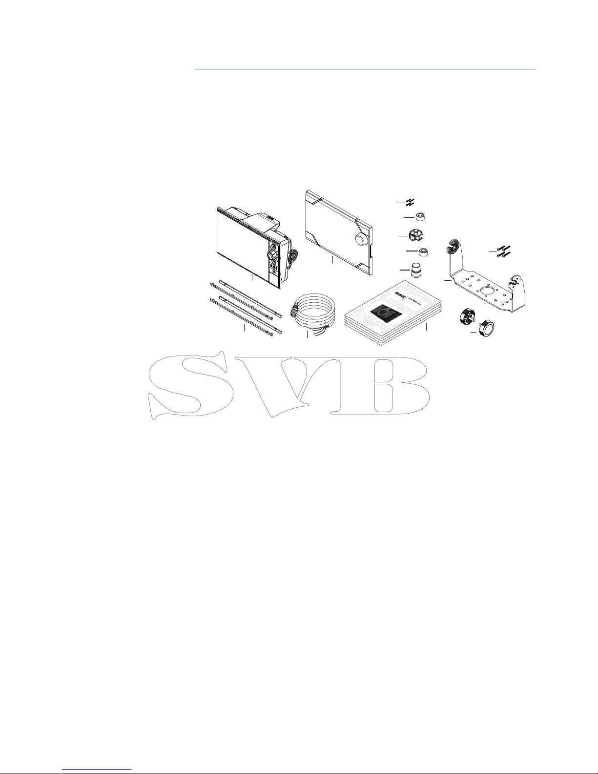
Included Items
1
3
2
11
4
12
13
5
7
8
9
10
6
E
NGLI
S
H
I
n
stall
a
t
i
on
Manual
band
g
.
c
om
E
NGLI
S
H
I
n
stall
ation
Manual
band
g
.
c
om
E
NGLI
S
H
In
stall
ati
on
M
anua
l
band
g
.
c
om
E
NGLI
S
H
I
n
stall
ati
on
Manual
band
g
.
c
om
E
NGLI
SH
I
n
stall
ation
Manual
band
g
.
c
om
1 Zeus display
2 Sun cover
3 Bezels trim (black and silver)
4 Power cable
5 Self tapping pozi screws, 4Gx1/2” (x4 for 7/9, x8 for 12)
6 Ethernet dust cap (x2 for Zeus 12)
7 HDMI dust cap (only for Zeus 12)
8 NMEA 2000 dust cap
9 Video/NMEA 0183 dust cap
10 Document pack (includes: installation manual, user manual, quick start guide,
templates, and warranty card)
11 Bracket
12 Bracket knobs
13 Self tapping pozi screws for bracket
Page 8
2 |
Zeus2 overview | Zeus Installation Manual
Front - controls
8
7
5
3
2
1
4
6
ZEUS 9/12 ZEUS 7
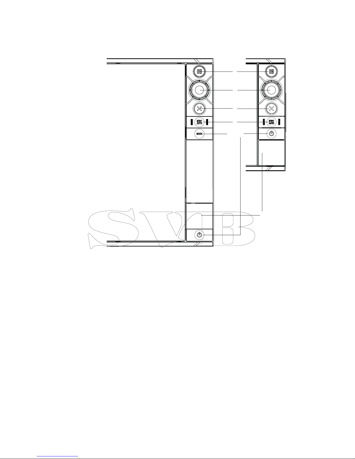
1 Touch screen - cursor control, chart panning and zoom, context related menus
2 Home key - opens home page for page selection and setup options
3 Rotary knob - zooming and menu scrolling / selection by press
4 Exit - exits menu dialogue, clears cursor from screen
5 STBY/AUTO - autopilot control
6 Mark - places waypoint at vessel location
7 Power - turns on unit, opens System Controls dialogue, long press turns o
8 Card reader door - access to dual card reader slot
Page 9
| 3
Zeus2 overview | Zeus Installation Manual
Rear - connections
5
31
4
54
21
3
1
ZEUS 9/12 ZEUS 7
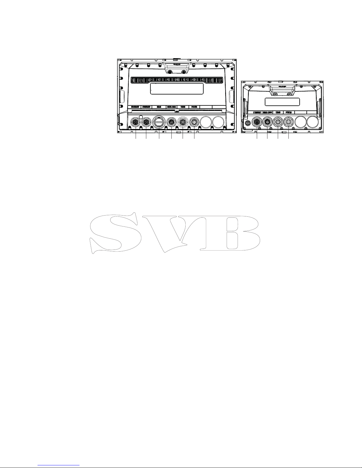
1 Ethernet - connection to high bandwidth network modules
2 HDMI - video output for external monitor
3 NMEA 2000 - dynamic data and user database sharing
4 Video - input for video sources such as cameras
5 Power - 12 V or 24 V supply input
Page 10
4 |
Hardware installation | Zeus Installation Manual
Hardware installation
Display mounting location
Choose the mounting locations carefully before you drill or cut; The display should be
mounted so that the operator can easily use the controls and clearly see the display screen.
B&G displays are high-contrast and anti-re ective, and are viewable in direct sunlight, but for
best results install the display out of direct sunlight. The chosen location should have minimal
glare from windows or bright objects.
If bracket mounting the display, choose an area where the display will not be subjected to
excessive vibration.
The mounting location will a ect the internal GPS receiver. Test the unit in it’s intended
location to ensure satisfactory reception. An external GPS source may be added to overcome
poor reception areas.
Leave su cient clearance to connect all relevant cables.
Check that it is possible to route cables to intented mounting location
Ensure that any holes cut are in a safe position and will not weaken the boat’s structure. If in
doubt, consult a quali ed boat builder.
Before cutting a hole in a panel, make sure that there are no hidden electrical wires or other
parts behind the panel.
Do not mount any part where it can be used as a hand hold, where it might be submerged, or
where it will interfere with the operation, launching or retrieving of the boat.
Choose an area where the unit will not be subjected to excessive vibration, or heat.
Choose a location that will not expose the unit to conditions that exceed the IP rating - refer
to “Speci cations” on page 39.
Note: Where ush mounted, the enclosure should be dry and well ventilated. The ventilation
of the space behind the unit should be enough to prevent excessive heat build up as a combined result of radiated heat o the heat sink, and sunlight heating of the enclosure. In very
small enclosures, it may be required to t forced cooling.
!
Warning: Inadequate ventilation and subsequent overheating of display may
cause unreliable operation and reduced service life. Ensure enclosure does not consistently exceed +55° C (+131° F) during normal daytime operation (in direct sunlight,
and at full screen brightness).
!
Warning: When installing, ensure appropriate safety equipment is used, e.g. ear
mu s, protective glasses, gloves and a dust mask. Power tools may exceed safe noise
levels, and can cast o dangerous protectiles. The dust from many materials commonly used in boat construction may cause irritation or damage to eyes, skin, and
lungs.
Page 11
| 5
Hardware installation | Zeus Installation Manual
Display installation
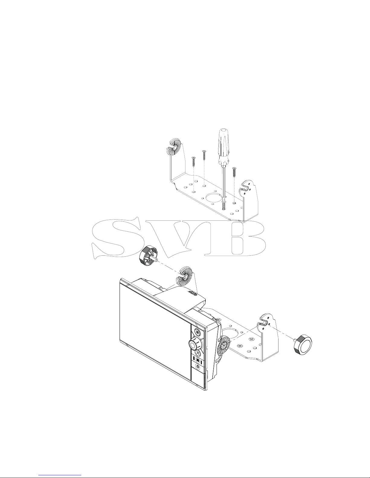
Bracket mounting
Place the bracket in the desired mounting location, and use a pencil or permanent marker to
mark drilling locations.
Note: ensure that the chosen location has enough height to accomodate the display tted in
the bracket, and allows tilting of the display. Also adequate space is required on both sides to
allow tightening and loosening of the knobs.
Use fasteners suited to the mounting surface material. If the material is too thin for self
tappers, reinforce it, or mount bracket with machine screws and large washers. Use only 304
or 316 stainless steel fasteners. Mark the screw locations using bracket as template, and drill
pilot holes.
Screw down the bracket.
Mount the display to the bracket using the knobs. Hand tighten only. The ratchet teeth in
the bracket and display case ensure a positive grip and prevent the unit changing from the
desired angle.
Page 12
6 |
Hardware installation | Zeus Installation Manual
Flush mounting
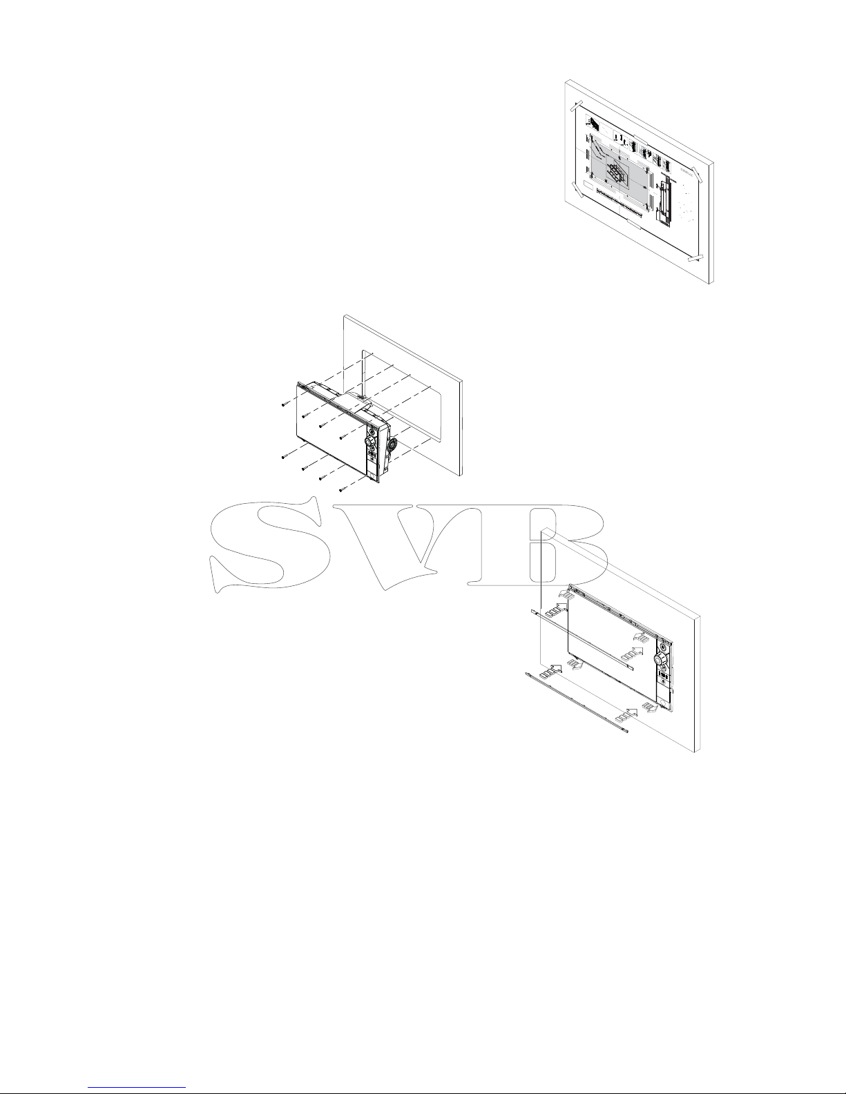
Check the template for scaling accuracy, using a tape
measure or ruler against the ruler printed on the
template.
Cut away excess paper if required, and tape template
to mounting surface. Check it is correctly aligned to a
vertical or horizontal reference. Do not use a bubble
level as vessel may be listing! Adjust where required.
Drill all marked pilot holes, then using an appropriate
saw, cut through the template and mounting surface,
along the dotted line bordering the shaded area of the
template.
Check the t of the display, and le away
remaining obstructions. Secure the display
with the supplied screws. Once screws are fully
tightened, ensure there is complete contact
with the mounting surface.
Bezel Fitment and Removal
When tting bezels, ensure hook tabs on
back of each bezel recess in to opposing
slots on screen frame. Once ush with front
surface of screen, slide top bezel to the left,
and bottom bezel to the right to lock in to
place. The bezel trim have been designed
to be very low pro le, and therefore fully
conceal the locking tabs that keep them
from being accidentally disengaged from
the mounting ange. To release the locking
tab, it is necessary to gently lever the centre
of the bezel trim away from the mounting
ange. To remove the cover, simultaneously
slide it sideways; to the right for the top
bezel, and to the left for the bottom bezel.
REMOVE SH
A
DED AREA
*98
8
-10455
-
001*
NO
TE:
DO
NO
T SCALE
PRI
N
T
1
:
1
IMPO
R
T
AN
T
.
Do
no
t u
se t
his
t
emp
l
a
t
e if
i
t
has
b
e
e
n
r
es
c
al
ed
by
c
opy
i
ng
o
r prin
n
g
.
If t
his
i
s
no
t
t
he
o
rig
i
nal, o
r
is
a
pr
i
n
t
f
r
o
m a
le, please check
t
he di
m
en
si
on li
n
es below ar
e
t
o
s
c
ale b
e
fo
r
e
us
e.
I
M
P
O
R
T
AN
T
.
N
e
pas u
l
i
s
er ce
g
abar
it
s
’
il
a
é
t
é p
hot
o
c
opié ou
imprimé en
f
orm
a
t
r
éduit ou ag
r
a
ndi. Si ce
g
aba
r
it n
’
e
s
t ni un
original ni un
e
v
e
r
s
ion i
m
pr
i
mé
e
d
’
un
ch
i
er PD
F
, v
euill
e
z
v
éri
er qu’i
l
e
s
t à l
’
é
c
h
e
l
le
a
v
a
nt de
l
’
u
lise
r
.
I
MPO
R
T
ANTE
.
no usar la plan
lla
si h
a
y peligr
o que la es
c
ala
o
r
igina
l
e
x
a
c
t
a se ha al
t
e
r
ado por
c
opias o pr
o
c
esos de
imp
r
esi
ón
im
p
r
e
ciso
s
.
S
i
es
t
o no es el original,
o un PD
F
,
v
eri
c
a
r
q
u
e
l
as
lí
neas a
ba
j
o
e
s
tán
a la
es
c
ala a
n
t
es
de
u
sa
r
.
WICHTIG. Diese
n
Vo
r
dr
u
ck nic
h
t
v
e
r
w
e
n
den,
w
enn er du
r
ch
K
op
i
e
r
en
oder Dr
u
c
k
en im Maß
s
t
ab
v
e
r
ä
n
dert wu
r
de. So
ll
t
e
es nic
h
t das
O
r
ig
i
n
a
l
o
d
er
e
in
P
D
FAu
sdr
u
ck
se
i
n
,
m
üs
s
e
n
u
n
ten
s
t
eh
e
nde
Z
eile
n
vo
r
e
r
w
endung
an
den rich
g
en
M
aß
s
t
ab an
g
epa
s
s
t
we
r
den.
B
EL
A
N
GRIJK.
G
e
bru
i
k d
e
z
e
m
a
l
n
i
e
t
i
n
d
ie
n
d
e
sch
a
a
l is
v
e
r
an-
de
r
d
d
o
or
d
a
t h
e
t
i
s
g
e
c
opiee
r
d o
f
g
ed
ru
k
t
.
I
n
dien d
e
z
e
ma
l
n
i
e
t
h
e
t ori
g
i
n
e
el
o
f
ee
n
pr
i
n
t
v
a
n
P
D
F
is
,
c
o
n
t
r
o
l
e
er
da
n
o
f
d
e
on
d
e
r
s
t
aan
d
e
li
j
nen de
ju
i
s
t
e
s
chaal z
i
j
n
v
o
o
r
d
a
t
u
z
e
g
e
b
r
u
i
-
kt
.
IMP
O
R
T
ANTE.
Nã
o
u
l
i
z
e
e
s
t
e
g
ab
a
r
i
t
o
se
a es
c
ala do mesm
o
v
e
r
sido
al
t
e
r
a
da
po
r
c
ó
p
i
a ou imp
r
ess
ão
. S
e
n
ão
f
o
r
o
o
ri
g
i
na
l
o
u
uma
c
ó
pia i
m
p
r
es
s
a
d
e
u
m
a
r
q
ui
v
o
P
D
F
,
v
eri
q
u
e
as
l
i
nh
a
s
abai
x
o
,
pa
r
a a
c
er
t
a
r
a
e
s
c
ala
a
n
tes
da
u
li
z
a
ç
ã
o
.
VI
K
T
IGT
.
A
n
v
ä
n
d
i
n
t
e
d
en
n
a
mall
om
d
en
s
k
a
l
a
ts
o
m
g
eno
m
u
t
skri
e
l
l
e
r
k
op
ier
i
n
g. Om
d
e
a
i
n
t
e är or
i
g
i
n
al
e
t
eller
en
utskri
f
r
å
n en PD
F
,
k
o
n
t
r
o
ll
e
r
a
a
lin
j
erna
n
ed
a
n
s
t
äm
m
e
r
m
e
d
s
k
al
an
i
nna
n
d
e
t
a
n
v
ä
n
ds
.
IMP
O
R
T
A
NT
E
. Non
u
lizz
a
r
e que
s
t
o
m
o
d
ello
se
è
s
t
at
o
ridi
m
e
nsio
n
a
t
o
c
opia
n
d
o
l
o
o
st
ampa
n
dol
o
.
S
e
qu
e
s
t
o
no
n
è
l’
o
ri
g
in
al
e
o l
a
s
t
a
mpa d
i
u
n
le
PD
F
,
v
e
ri
c
a
r
e se le linee che
seguo
n
o
d
e
v
o
n
o esse
r
e
d
im
e
nsi
on
a
t
e prima di
e
ss
e
r
e
u
l
iz
z
a-
t
e
.
T
ÄR
K
E
Ä
Ä
.
Älä
k
ä
y
t
ä
t
ä
t
ä
k
a
a
v
i
o
t
a,
jos
sen
mi
a
k
a
a
v
a on
m
u
u
u
n
u
t
k
opio-i
de
ss
a
t
ai tulo
s
t
a
e
s
s
a.
J
os
t
äm
ä ei o
l
e
al
k
u-
pe
r
äi
n
en
t
ai
P
DF tu
l
o
s
t
e
t
arki
s
t
a
r
aj
a
t
m
i
a
k
a
a
v
a
s
t
a
a
l
la
en
n
en
k
ä
y
ö
ä.
⊼
ᛣ
˖
䇋
ሑ
䞣
ϡ㽕
Փ
⫼ᴀᅝ㺙ᣪ
ᄨ
ሎᇌ
⠜
ⱘ
ӊ
DŽ
བ
ᵰ
Փ
⫼
ӊˈ
߭
Փ
⫼
Пࠡ
䇋⹂
䅸݊
↨
՟ϔ
ᅮ
㽕
Ϣ
ӊ
ᇣ
ᖙ乏ϔ
㟈
DŽ
㩅
㟈
aG⸩㇠
⇌
G
㻐
⥙
㡰
⦐
G
䆠
ὤᴴ
G㦤
㥉G
═
G
㟤
G
㢨
G䊐䙀⫳㡸
G
㇠㟝
䚌㫴
G⫼㐡
㐐㝘
UG
㠄⸬
㢨G
㙸
⏼
ᶤ
⇌
G㢬㋸Ɒ㢨⮨SG
㇠㟝
䚌ὤ
G㤸G㙸⣌G㾌㍌㉔㢌G⌼
Ἴ
㡸G
䞉㢬
G
䚨
G㨰㐡㐐㝘
U
謗
ஔ
အြ႒
ႿႣ
Ⴘ
ー
႔
ွ襙
蕧ၒ
ၿႠ
ー
္ၖေ
ဴ
貽谞
ယ
変
ၝ
ေ
ဴ
ဒ
ၙ
အ
ံ
ယတၘ
၌
ဧ
ြဵ萦
蠯
ဥးဒ
ဵ
踆
ဣ
ဒ
ଟ
႒
ႿႣႸ
ー
႔
ယ
ၶ
Ⴖ
ႄ
႖
Ⴗြၐြ
ဵ
းဒ见踵္ွଞ踆
ြ
貎
茽
蓧
ၠ萦ေဴ貽谞ၠ輑襨ဥဴဝီ
ဣဒ
ଟ
ɩɴ
ɯɳɧ
ɴ
ɯɬaGɴʌG
ʏ
ʘʖʕʒʣʎʚʐ
ʙ
ʌG
ʤ
ʙʚGʏʔʘʙʗʚʑʝʏʥS
G
ʌʘ
ʒʏGʕʔʇ
G
ʈʢ
ʒʇ
Gʏʎʓ
ʌʔʌ
ʔ
ʇ
Gʉ
G
ʗ
ʇʎ
ʓ
ʌ
ʗʇʜG
ʖ
ʗ
ʏGʑʕʖʏʗʕʉʇ
ʔʏ
ʏGʏʒ
ʏG
ʗ
ʇ
ʘ
ʖʌ
ʞʇʙ
ʑʌ
U
G
ɬʘ
ʒʏ
G
ʉ
ʢ
Gʏ
ʘ
ʖ
ʕ
ʒʣ
ʎʚʌʙʌ
Gʔ
ʌ
Gʕʗ
ʏʊʏ
ʔ
ʇ
ʒ
S
Gʇ
Gʗ
ʇ
ʘ
ʖ
ʌʞ
ʇ
ʙ
ʑʚG
ʏ
ʎG
ʛʇ
ʐʒʇS
G
ʚʈʌʋʏ
ʙ
ʌ
ʘʣG
ʉ
G
ʘʕʕ
ʙʉʌʙ
ʘʙ
ʉ
ʏ
ʏGʗʇ
ʎ
ʓʌʗʕ
ʉ
G
ʒʏʔ
ʌʐʑ
ʏ
G
ʉ
G
ʔ
ʏʍ
ʔ
ʌʐG
ʞ
ʇ
ʘ
ʙʏGʏ
ʔʘʙʗʚʑʝʏ
ʏ
GʘG
ʋʌ
ʐʘʙʉʏʙʌʒ
ʣ
ʔʢʓʏGʗ
ʇ
ʎ
ʓʌ
ʗʇ
ʓʏU
Check dimensions before cutting
1
2"
3
0
0
m
m
L
C
L
C
192.5 mm (7.58")
186.0 mm (7.32
"
)
192
.5
m
m
(7.
5
8")
1
86.0 mm
(7.
32
")
20
0
.0
m
m
(7.
87
")
117.5 mm (4.63")
111.0 mm (4.37")
130.0 mm (5.12")130.0 mm (5.12")
117.5 mm (4.63")
111.0 mm (4.37")
2
0
0.0
mm
(7.8
7")
385
.0
mm (15
.
16")
3
72
.0
mm
(
14
.
65
"
)
4
00
.0
mm
(
15
.
75
"
)
235.0 mm (9.25")
222.0 mm (8.74")
260.0 mm (10.24")
MO16
Marine Monitor
X4
1
3
x4
x2
4
C
L
I
CK
5
6
7
2
Page 13
| 7
Wiring | Zeus Installation Manual
Wiring
Guidelines
Care must be taken when running cables in a boat, to ensure that the cables are protected
from damage and do not interfer with mechanical systems such as throttle cables and hatch
covers.
At each end of a cable, it is advisable to leave a short loop hanging lower than the termination
point. This prevents any water that may get in contact with the cable from running down it to
termination points vulnerable to corrosion.
Extending cables should be done with suitable crimp connectors or solder and heat shrink.
Keeps joins as high as possible to minimize possibility of water immersion.
Routing cables adjacent to high current or high frequency signal cables could cause noise to
be induced from one device to another. Allow spacing between cables where possible.
Secure all cables at regular intervals, to prevent movement during boat operation. Cable
movement may cause fatigue at termination points or cause the cable to interfere with other
boat systems.
Allows enough cable slack for easy access to connectors when removing the device from a
bracket or ush mount installation.
!
Warning: Before starting the installation, be sure to turn electrical power o . If
power is left on or turned on during the installation, re, electrical shock, or other
serious injury may occur. Be sure that the voltage of the power supply is compatible
with the Zeus2 display
!
Warning: The positive supply wire (red) should always be connected to (+) DC with
the supplied fuse or a circuit breaker (closest available to fuse rating).
Power connection
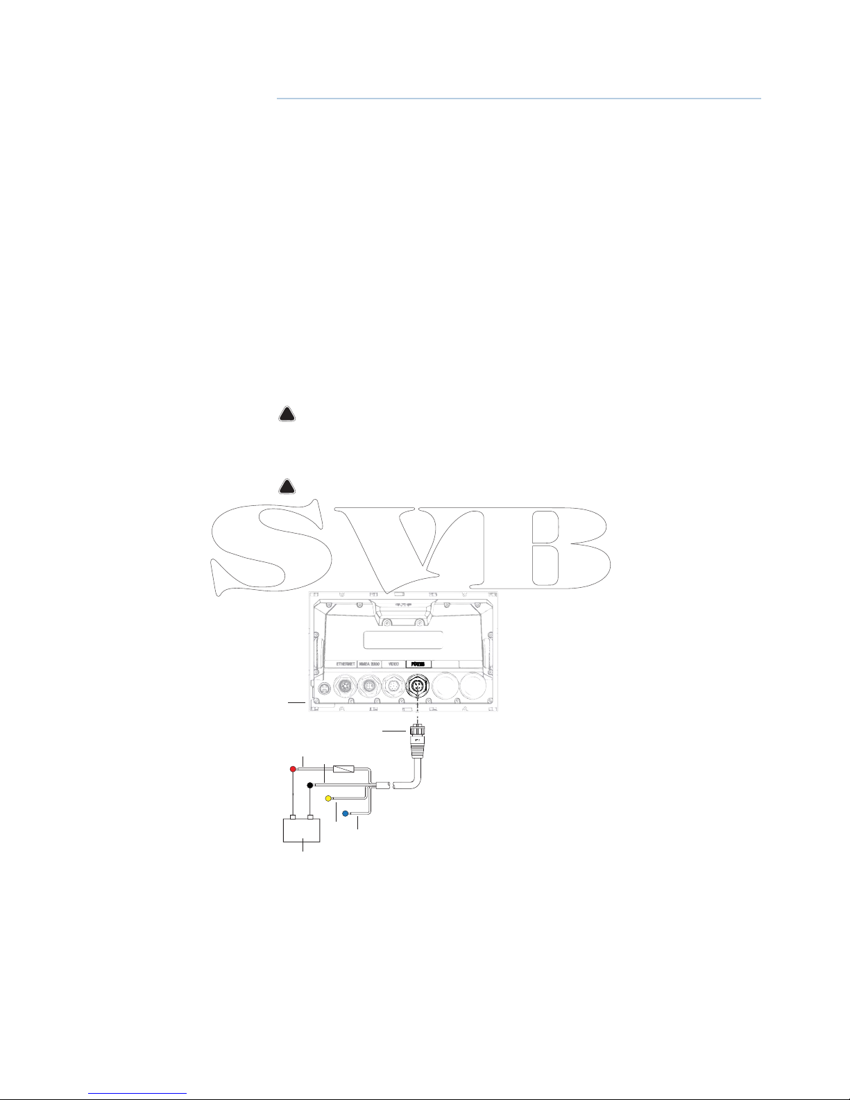
Zeus displays are designed to be powered by a 12 or 24 V DC system. They are protected
against reverse polarity, under voltage and over voltage.
+
_
2
3
4
6
7
5
1
1 Zeus display
2 Four pin power cable
3 Positive supply, 12/24V (red wire)
4 Negative (black wire)
5 Power control (yellow wire)
6 Alarm output (blue wire)
Page 14
8 |
Wiring | Zeus Installation Manual
Power Control connection
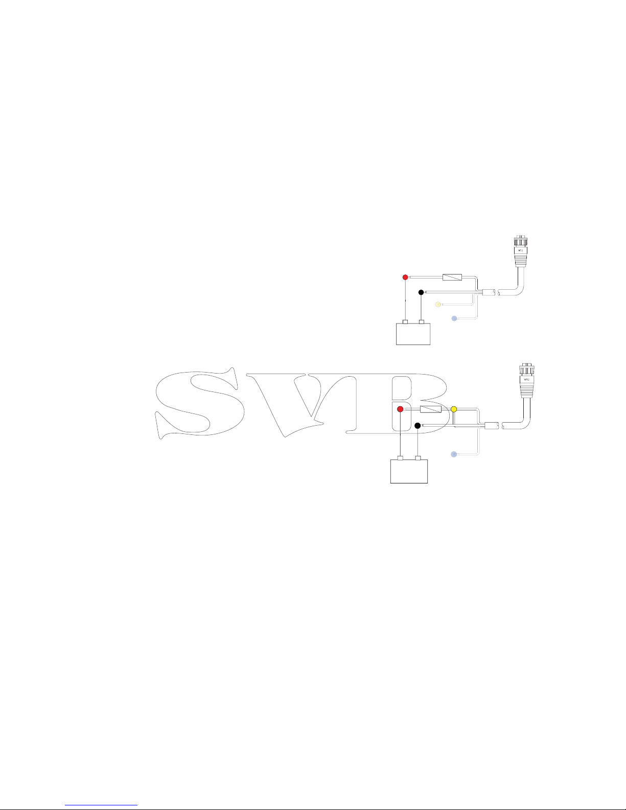
The yellow Power Control wire on the Zeus power cable can either be an input that will turn
on the processor when power is applied, or an output that turns on other devices when the
processor is powered on. It can be con gured at the installation stage to control the power
state of displays and compatible devices. When commissioning the system, the Zeus can be
set to be a Power Control Slave or Power Control Master.
Power Control con guration options of the Zeus are:-
• Zeus to turn on when power key pressed: Yellow wire not connected
• Zeus to turn on when power source is turned on: Common red and yellow wires
• Zeus to turn on with power key, as well as other compatible devices such as Broadband
Radar: Yellow wire connected to a Power Control Bus. (Set one or more displays to be a Power
Control Master)
Power Control unconnected
Device will turn on and o when the power
button on the front of the unit is pressed.
Leave yellow Power Control wire disconnected.
Tape or heat-shrink end to prevent shorting.
Power Control to supply positive (auto on)
Device will turn on immediately when power is
applied. Common the yellow wire with the red
wire after the fuse.
Note: The unit can not be powered down by
power button, but can be put in to standby
mode. (screen backlight also turns o ).
+
_
+
_
Page 15
| 9
Wiring | Zeus Installation Manual
Power Control master/slave bus
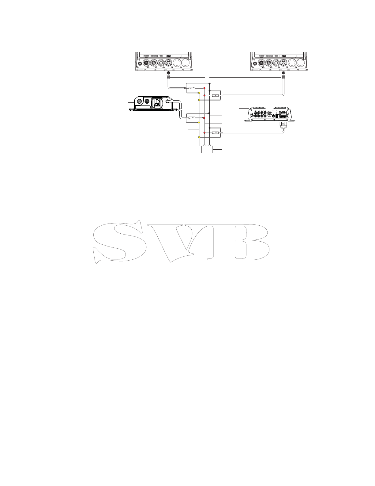
Turning on the ‘master’ device turns on connected ‘slave’ devices.
1 Zeus displays
2 Power cable
3 Radar Interface box
4 Sonic Hub
5 Ground wire
6 Positive wire
7 Power control wire
If the left Zeus turns on using the power button and is set as the Power Control Master, it will
output voltage on the Power Control bus to power on the other Zeus, the Radar Interface,
and the SonicHub.
If the right Zeus is set to Power Control Slave, it cannot be powered down using its own
power button, but can be set to standby.
If the left Zeus (Power Control Master) is o , the right Zeus can be turned on using its own
power button, but won’t turn on any other devices.
To turn on all network devices from either Zeus, both devices can be con gured as Power
Control Masters.
Note: If an Zeus has its power state controlled by another device (or ignition switch), it can’t
be totally powered down. It can however enter a standby state to save power. If the power
button is pressed and Power O selected, a message will appear “Preparing to standby…”
External alarm
Blue wire on power cable:
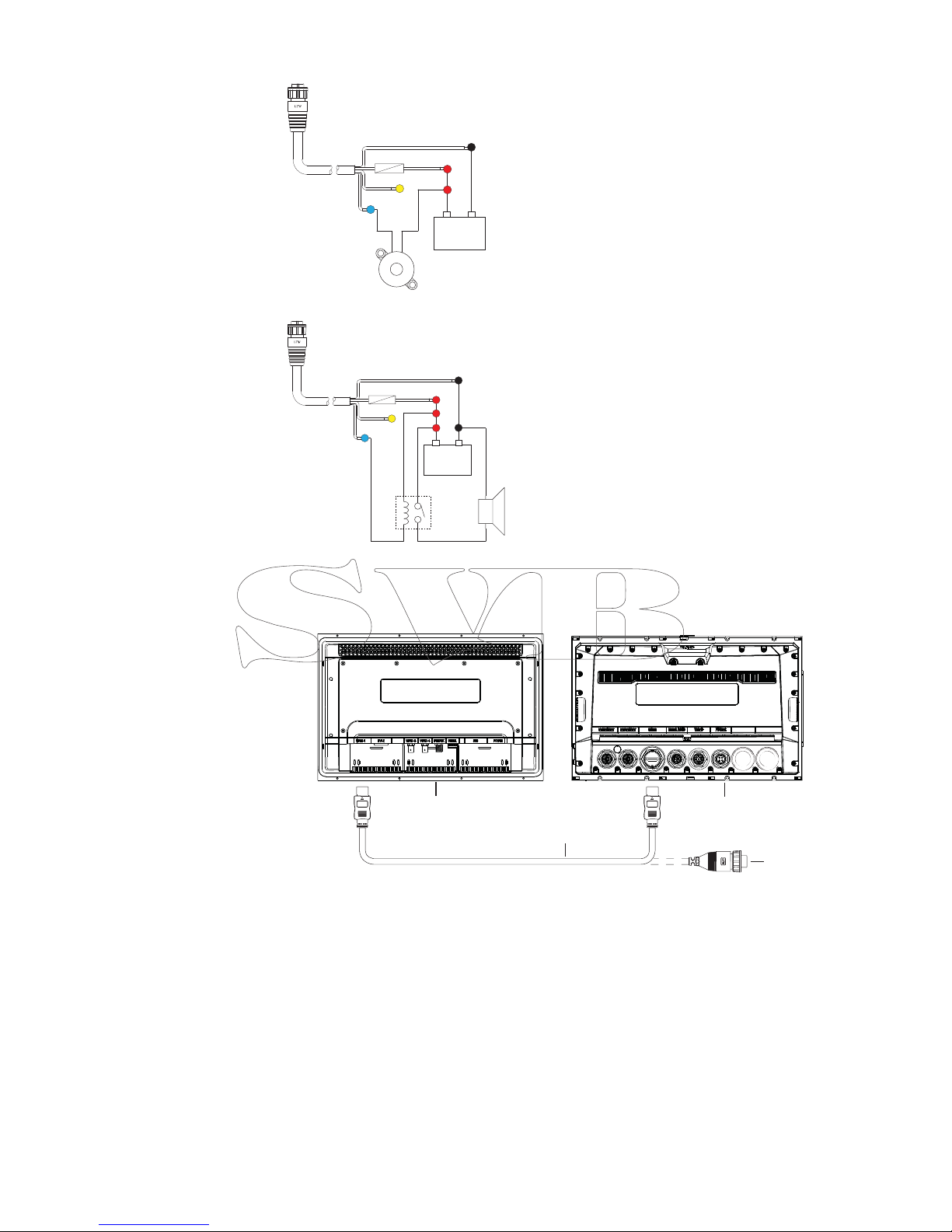
An external alarm can be connected to one or more Zeus displays on the network. The
external alarm can be a small peizo buzzer connected directly, or a horn siren connected via a
relay.
Alarms are con gured globally in the system i.e they can be con gured on any one
networked multifunction device or Triton instrument, and be seen, heard, and acknowledged
from all devices. Individual devices can also be con gured to not to sound their internal
buzzer, but still display the alarm information. For information on con guring alarms, refer to
the Alarms section in the Operator manual.
+
_
6
3
2
7
8
5
4
1
Page 16
10 |
Wiring | Zeus Installation Manual
+
_
For sirens that draw more than 1 Amp, use a relay
+
_
Connect an external monitor
The Zeus 12 o ers an HDMI output which can be connected to an external monitor to
replicate video at a remote location.
1
3
2
4
1 MO series monitor
2 HDMI cable
3 Zeus 12
4 HDMI cable - waterproof connector (use in exposed installations)
Note: If connected to an HDTV it is possible the image may appear cropped, ie missing some
detail at the outer edges of the screen. This is usually due to overscan applied by the TV. Refer
to your TV operator manual to nd if and how overscan can be turned o .
Page 17

| 11
Wiring | Zeus Installation Manual
NMEA 2000 – connection to backbone
Device connection
The Zeus multi function displays are equiped with an NMEA 2000 data port, which allows the
receiving and sharing of a multitude of data from various sources.
Essential network information
• The standardised physical cables/connectors for NMEA 2000 are ‘Micro-C’ and ‘Mini-C’,
directly derived from the automation industy’s ‘DeviceNET’ - ‘Micro-C’ being the more
commonly used size.
• A network consists of a linear ‘backbone’ from which ‘drop cables’ connect to NMEA 2000
compliant devices
• A single drop cable has a maximum length of 6 m (20 ft). The total length of all drop cables
combined should not exceed 78m (256 ft)
• A NMEA 2000 network, using Micro-C cabling, has a maximum cable length of 100 m (328 ft),
between any two points
• A NMEA 2000 network needs to have a terminator at each end of the backbone. A terminator
can be one of the following:
• a terminator blank plug
• a wind transducer (where the mast cable is one end of the backbone)
Planning and installing a network backbone
The Micro-C backbone needs to run between the locations of all products to be installed typically in a bow to stern layout - and be no further than 6 m from a device to be connected.
Choose from the following components to make up the backbone:
• Micro-C cables: 0.6 m (2 ft), 1.8 m (6 ft), 4.55 m (15 ft), and 7.58 m (25 ft) cables
• T-connector. Used to connect a drop cable to the backbone
• Micro-C power cables. Connected to backbone via a T-connector
Note: When using a wind sensor, the mast cable should be connected at one end of the
backbone, as the sensor is tted with a termination resistor.
Note: Most NMEA 2000 devices can be connected directly to a SimNet backbone and SimNet
devices can be connected to a NMEA 2000 network by using adapter cables.
Note: B&G devices are fully compatible with a SimNet network by using a Micro-C to SimNet
adapter cable.
Note: Triton displays have two Micro-C connectors, and can either be connected inline with
the backbone, or wired individually o a drop cable. Connecting from device to device is
known as ‘daisy chaining’ This network topology is not o cially NMEA 2000 compliant.
Power the network
The network requires its own 12 V DC power supply protected by a 5 amp fuse or breaker. For
vessels tted with 24 V systems, use a DC-DC converter to supply 12 V.
Connect power at any location in the backbone for smaller systems.
For larger systems introduce power at central point in the backbone to “balance” the voltage
drop of the network.
Note: If joining to an existing NMEA 2000 network that already has its own power supply, do
not make another power connection elsewhere in the network, and ensure existing network
is not powered by 24 V DC.
Note: Do not connect the NMEA 2000 power cable to the same terminals as the engine start
batteries, autopilot computer, radar, bow thruster or other high current devices.
Page 18
12 |
Wiring | Zeus Installation Manual
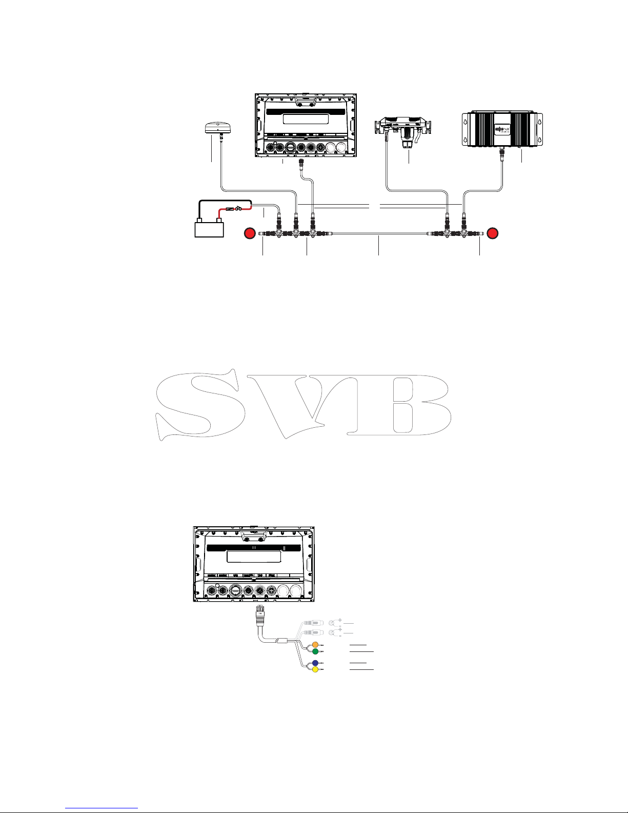
The following drawing demonstrates a typical small network. The backbone is made up of
direcly interconnected T-piece joiners and an extension cable, which is terminated at each
end.
+
_
12 V DC
TT
9
8
5
7
6
4
3
2
1
9
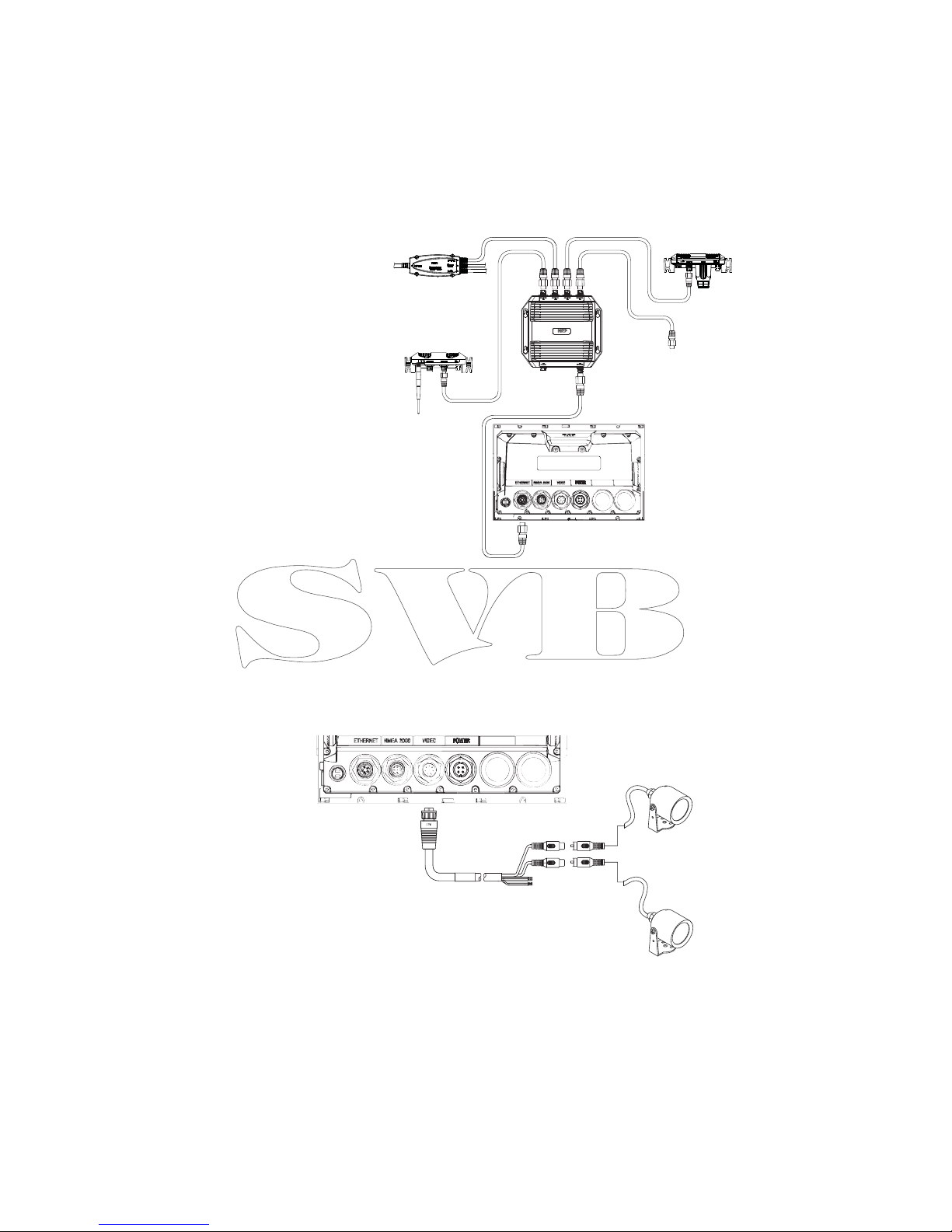
1 GPS antenna
2 Zeus
3 Broadband radar interface
4 SonicHub
5 ‘Drop’ cables (should not exceed 6m (20’) each)
6 Power cable
7 Micro-C T junctions
8 Backbone
9 Micro-C terminator (one male, one female)
NMEA 0183 device connection
The Zeus display has an NMEA 0183 serial port, providing both an input and an output.
The port uses the NMEA 0183 (serial balanced) standard, and can be con gured in the
software for di erent baud rates up to 38,400 baud.
1 NMEA 0183 RX_B (orange)
2 NMEA 0183 RX_A (green)
3 NMEA 0183 TX_B (blue)
4 NMEA 0183 TX_A (yellow)
Note: The connector for NMEA 0183 is labelled VIDEO, as the cable is dual purpose and carries
both composite video and NMEA 0183 (on seperate wires).
Talkers and Listeners
Do not connect multiple devices outputing data (Talkers) on to the serial input (Rx) of the
unit. The NMEA 0183/RS422 standard is not intended for this type of connection, and data
will be corrupted if multiple devices transmit simultaneously. The output however may drive
A
B
+
+
-
-
RX_B
RX_A
TX_B
TX_A
1
2
3
4
Page 19
| 13
Wiring | Zeus Installation Manual
multiple receivers (Listeners). The number of receivers is nite, and depends largely on the
receiving hardware. Typically driving three devices is possible.
Ethernet device connection
Ethernet is used to interconnect high bandwidth devices such as radar, sonar, and other
multi function displays. The Zeus 7/9 have one ethernet port, whereas the Zeus 12 has two.
Connection of network devices can be made directly, or via a NEP-2 ethernet expansion port.
Additional NEP-2s can be added to provide required number of ports.
Note: some ethernet devices are equiped with two or more ethernet ports, which allow con-
nection of additional devices, and may eliminate the need for an extra NEP-2.
Video in
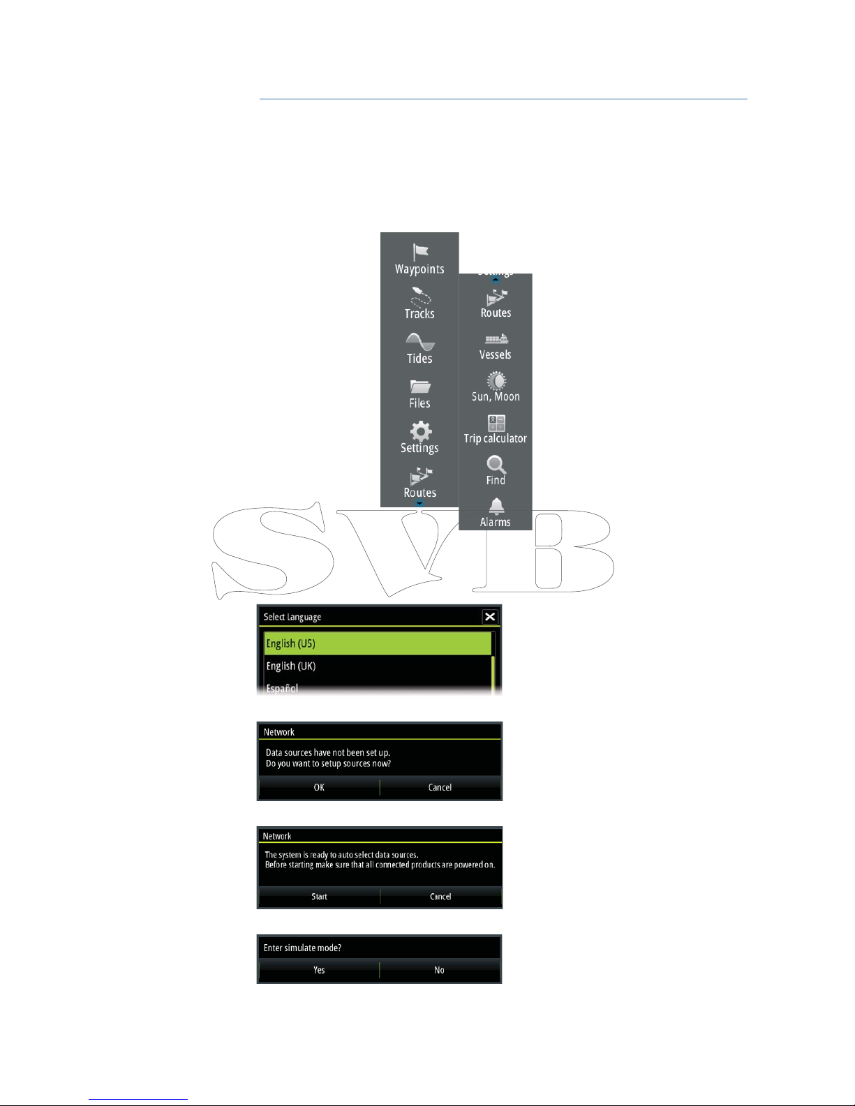
Each Zeus can be connected to two composite video cameras, and display video images on
its displays. Both NTSC and PAL formats are supported. The Zeus video input cable is tted
with female RCA plugs - the camera cables should be terminated with male RCA cables to
suit.
VIDEO 1
VIDEO 2
RED
GREEN
Note: The video images will not be shared with another unit via the network. It is only pos-
sible to view video on the unit connected to the video source.
Page 20
14 |
Software setup | Zeus Installation Manual
Software setup
The Zeus requires some initial con guration before use, in order to get the most out of the
product.
The following sections focus on settings that typically will not require change once
con gured. User preference settings and operation are covered in the operator manual.
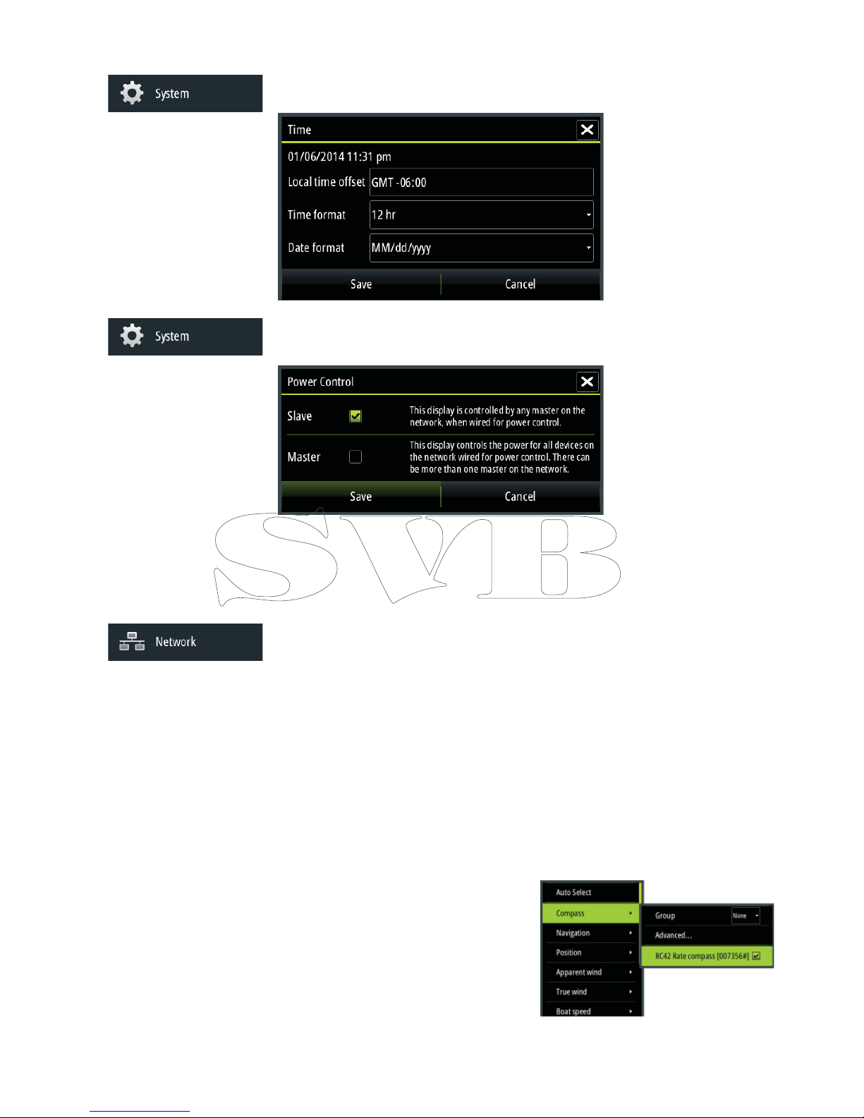
Pressing the home key brings up the home page, which has three distinct panels.
The scrollable left column of icons access most settings that require con guration;
First time startup
When the Zeus is started for the rst time, or after a factory default, the unit will raise
prompts requesting the user to select some fundamental setup options;
Choose language.
Initiate source selection for data sources both internal and external to device.
Check all external data sources and NMEA 2000 data bus are turned on.
Simulation uses recorded data to allow product demonstration of features otherwise not
possible without physical installation on a vessel.
Page 21
| 15
Software setup | Zeus Installation Manual
Time and Date
Con gure time settings to suit vessel location.
Power Control setup
Determines unit response to signal applied to yellow wire of power cable.
These settings do not require adjustment if the yellow wire is connected to ignition or to a
stand-alone switch that applies 12V/24V.
Note: The System Controls menu will not display the ‘Power O ’ option when unit is con g-
ured as slave. To power down device, the master device must be powered down, or system
power removed.
Source selection
Data sources provide live data such as GPS position, heading, wind speed, and temperature.
The data may originate from modules internal to the device (eg internal GPS), or external
modules connected via NMEA 2000 or NMEA 0183. The internal ‘virtual’ devices typically
include echo, MFD, Navigator, Pilot Controller, and iGPS. When a device is connected to more
than one source providing the same data, the user has the exibility to choose the prefered
source. Before commencing with source selection make sure all external devices and the
NMEA 2000 bus are connected and are turned on.
Auto Select
The Auto Select option will look for all sources connected to the device. If more than one
source is available for each data type, selection will be made from an internal priority list. This
option will be suitable for the majority of installations.
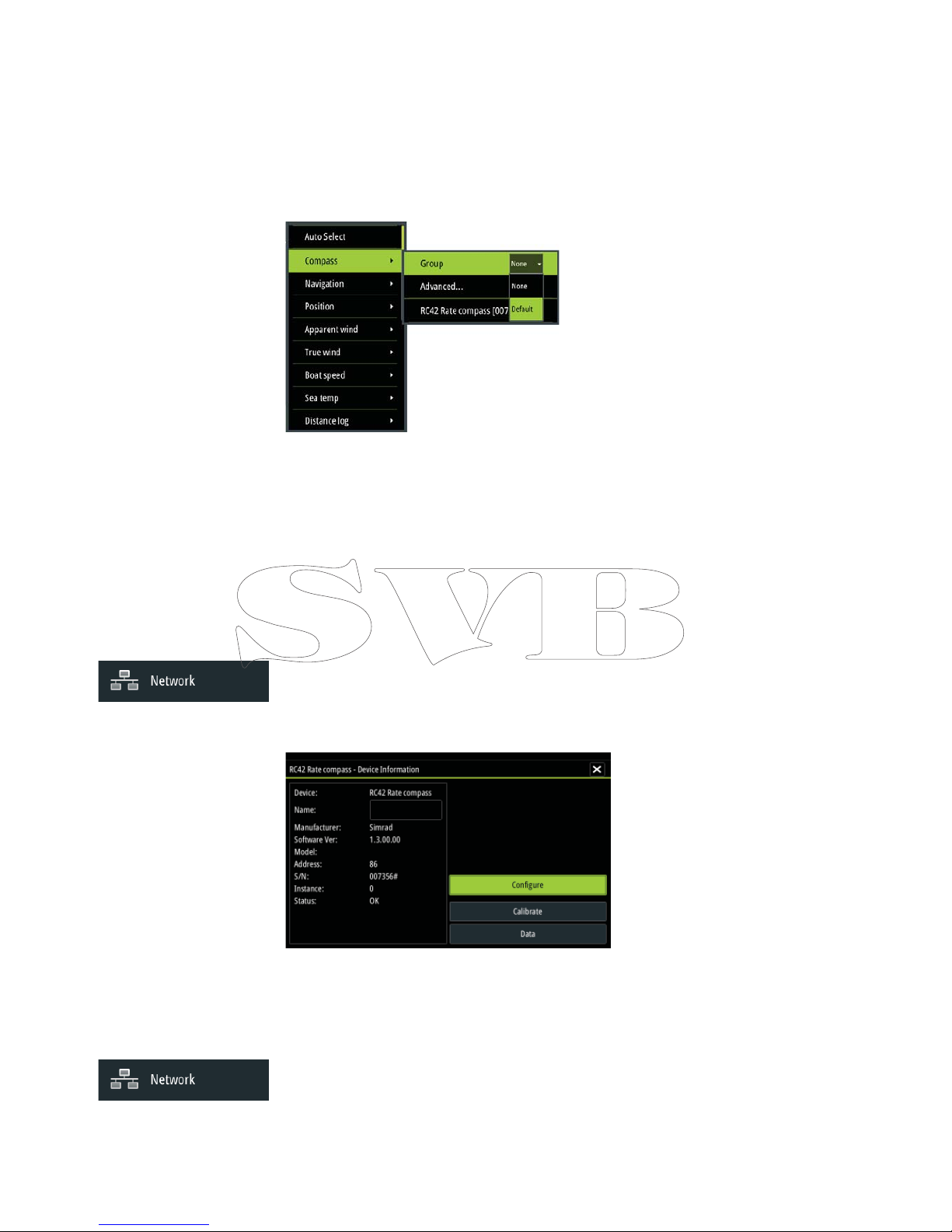
Manual source selection
Manual selection is generally only required where
there is more than one source for the same data,
and the automatically selected source is not the
one desired.
Page 22
16 |
Software setup | Zeus Installation Manual
Group source selection
B&G multifunction displays, autopilot controllers, and instruments have the ability to;
• use data sources (eg position, wind direction, etc) that all other products on the network use,
or alternatively use a data source independently from other units.
• globally change all displays over to a di erent source from any display. (This will only include
products set to Group mode.)
In order to enable group selection, the display must be set to ‘Default’ group.
Devices with Group set to None can be set to use di erent sources to those of the rest of the
network devices.
Advanced source selection
This allows the most exible and precise manual control over which devices provide data.
Some data sources, such as those for fuel level, or engine RPM, can only be changed via the
Advanced menu. Occassionally Auto Select may not assign the desired source, which may be
corrected using the Advanced Source Selection. An example of this is where twin installations
with NMEA 2000 compliant engines are not programmed with unique instance numbers.
This means that the auto select feature can’t determine which engine is tted on the port and
which is tted on the starboard side.
Device list
The device list shows the physical and virtual devices that provide data. This may include a
module inside the Zeus, the NMEA 0183 port, or any external NMEA 2000 device.
Selecting a device in this list will bring up additional details and actions:
All devices allow allocation of an instance number via the Configure option. Set unique
instance numbers on any identical devices on the network. The Data option shows all data
being output by the device. Some devices will show additional option(s) speci c to the
device - the RC42 illustrated above has a Calibration option, to allow easy setup of this device
which does not have it’s own user interface.
Network Groups
It is possible to group certain settings so they are duplicated across the network on multiple
displays. Display (ie backlighting), Units (ie metric, imperial), Damping (to dynamic data), and
Alarms can be grouped either in ‘Default’ group, or groups ‘1’ through to ‘6’. If any of the
settings require discrete control, set it to ‘none’.
Page 23

| 17
Software setup | Zeus Installation Manual
Diagnostics
The NMEA 2000 tab on the diagnostics page can provide information useful for identifying an
issue with the network.
Bus state simply indicates whether the bus is powered, but not necessarily connected to any
data sources. However if bus shows as ‘o ’, but power is present along with an increasing error
count, it is possible that termination or cable topology is incorrect.
Rx Over ows: The CAN driver got too many messages for its bu er before the application
could read them.
Rx Overruns: The CAN hardware got too many messages for its bu er before the CAN driver
could read them.
Rx/Tx Errors: These two numbers increase when there are error messages, and decrease when
messages are received successfully. These (unlike the other values) are not a cumulative
count. Under normal operation these should be at 0. Values around 96 upwards indicate
a heavily error prone network. If these numbers go too high for a given device, it will
automatically drop o the bus.
Fast Packet Errors: Cumulative counter of any fast packet error. This could be missed frame, or
frame out of sequence etc. NMEA 2000 PGNs are made of up to 32 frames. The entire message
will be discarded when a frame is missed.
Note: Rx and Tx Errors often indicate an issue with the physical network, which may be
resolved by correcting termination, reducing backbone or drop lengths, or reducing the
number of network nodes (devices).
External Alarm Setup
The ‘Siren Enabled’ option must be set in order for the unit to drive the buzzer when an alarm
condition arises. Its setting also determines the operation of the external alarm output.
Radar setup
Setup and con guration of the Broadband radar has been simpli ed compared to traditional
pulse radars. There is no zero range (time delay), no warm up time, and no burn-in required..
Radar source
In a system with more than one radar, the correct device to con gure can be selected from
this menu.
Note: some radar like the broacband 4G support dual radar mode, and therefore are repre-
sented twice in the source list, with an A and B su x.
Radar status
Page 24

18 |
Software setup | Zeus Installation Manual
Scanner type
Identi es the model of scanner connected to the network.
Software version
Check to make sure you have the latest software. check website for the latest version.
Serial Number
This number should be recorded for support and insurance purposes.
MARPA status
The MARPA status can identify if a heading sensor is on the network and that the radar is
receiving heading information essential for MARPA calculations.
Reset device ID
The earlier Zeus models only support one radar on the network. Should a radar be connected,
that has been connected to a dual radar network in the past, it may not be detected by the
Zeus because it may have an invalid Device ID. With the radar connected and power up,
select the Reset Device ID button to resolve this problem.
Note: This procedure must be performed with only one radar on the network, and only ap-
plies where a network combines Zeus with Zeus.
Adjust bearing alignment
This is to align with the heading marker on the screen with the center line of the vessel, this
will compensate for any slight misalignment of the scanner during installation. Any inaccuracy
will be evident when using MARPA or chart overlay.
Point the boat to be perpendicular to the very end of a breakwater or peninsula. Adjust the
bearing alignment setting, so that the heading marker and land mass intersect.
Adjust antenna height
Set the radar scanner height relative to the water surface. The Radar uses this value to
calculate the correct STC settings.
Adjust local interference reject
Interference from some onboard sources can interfere with the Broadband radar. One
symptom of this could be a large target on the screen that remains in the same relative
bearing even if the vessel changes direction. Choose from Local interference rejection LOW,
MED or HIGH. Default is LOW
Sidelobe suppression
Occasionally false target returns can occur adjacent to strong target returns such as large
ships or container ports. This occurs because not all of the transmitted radar energy can be
focused into a single beam by the radar antenna, a small amount energy is transmitted in
other directions. This energy is referred to as sidelobe energy and occurs in all radar systems.
The returns caused by sidelobes tend to appear as arcs.
Note: This control should only be adjusted by experienced radar users. Target loss in harbour
environments may occur if this control is not adjusted correctly.
When the radar is mounted where there are metallic objects near the radar, sidelobe energy
increases because the beam focus is degraded. The increased sidelobe returns can be
eliminated using the Sidelobe Suppression control in the Radar installation menu.
By default this control is set to Auto and normally should not need to be adjusted. However
if there is signi cant metallic clutter around the radar, sidelobe suppression may need to be
increased. The control should be adjusted as follows:
• Set Radar range to between 1/2 nm to 1 nm and Sidelobe Suppression to Auto.
• Take the vessel to a location where sidelobe returns are likely to be seen. Typically this would
be near a large ship, container port, or metal bridge
• Traverse the area until the strongest sidelobe returns are seen.
• Change Auto sidelobe suppression to OFF then select and adjust the sidelobe suppression
Page 25
| 19
Software setup | Zeus Installation Manual
control until the sidelobe returns are just eliminated. You may need to monitor 5-10 radar
sweeps to be sure they have been eliminated.
• Traverse the area again and readjust if sidelobes returns still occur.
• Exit the installation menu.
Restore radar to Factory Default
This can be used to revert all user adjustments.
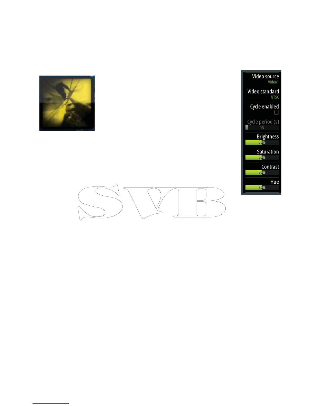
Video In con guration
Press the menu key when on the video page or panel to open the setup
dialogue.
Enable PAL or NTSC depending on the video ouput standard of the
selected camera.
You can optimize the video display by adjusting the video image
settings (brightness, saturation, etc.). The settings are applied individually
for each video source.
Mirror image may be applied where the camera is providing a rear view,
and the user wishes to see objects as they would appear in a vehicle
rearview mirror, ie, on the same side as they actually are.
Page 26
20 |
Software setup | Zeus Installation Manual
Autopilot setup
Verifying the autopilot connection
When an AC12N, AC42N, or SG05 is connected to the Zeus system, the Zeus will
automatically detect the autopilot and an Autopilot menu icon will be included in the
‘Settings’ menu.
If no ‘Autopilot’ icon is available in the menu, establish the connection by running the auto
select process.
If the AC12N, AC42N or SG05 is turned o independantly of the display, the ‘Autopilot’ menu
icon will remain available, but only a few of the menu items will be available.
Commissioning the autopilot
When the autopilot installation is completed, the commissioning procedures must be
performed. Failure in setting up the autopilot correctly may prohibit the autopilot from
functioning properly.
The setup of the autopilot computers (AC12N/42N) can be done in full from compatible B&G
displays that feature AP control, or a Triton display. The following sections describe how you
con gure the autopilot from the Zeus unit.
If you connect the Zeus to an already commissioned autopilot system, you only have to do
an automatic source selection as described above before the autopilot is ready to be used.
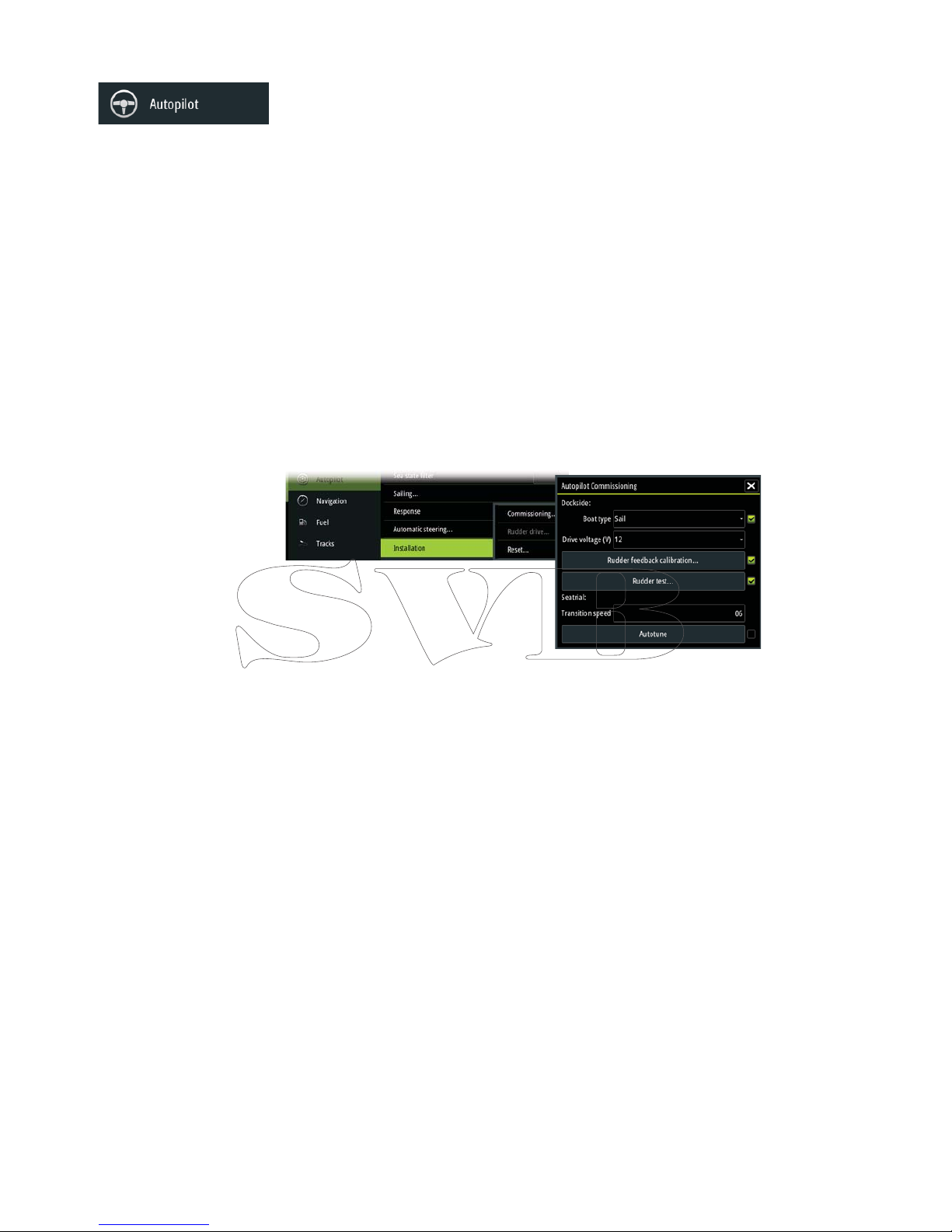
Dockside setup
Initiating the required dockside setup is done from within the Commissioning dialog.
Completed procedures are labelled with a tick.
When the autopilot computer is delivered from factory AND ANY TIME AFTER AN AUTOPILOT
RESET HAS BEEN PERFORMED, you will have to run a complete setup again.
All steps in all commissioning procedures are clearly described on-screen, and you will be
guided step by step through the process.
1. Press the ‘STBY/AUTO’ key to ensure that the autopilot is in standby mode
2. Activate the autopilot commissioning dialog as shown above
3. Select boat type
• The boat type setting is used by the system to select appropriate preset steering parameters.
It will also a ect available autopilot features.
4. Perform the rudder calibration
• Used if you have a rudder feedback unit installed. This calibration is used to ensure that the
physical rudder movement corresponds to the rudder angle displayed on the Zeus unit.
VRF (Virtual Rudder Feedback) calibration
• The Virtual Feedback option enables your autopilot to steer without a conventional rudder
feedback unit. This function is designed for vessels up to 40 ft. powered by outboard or stern
drives only.
• The Virtual Feedback option will only be available when there is no feedback unit connected
at rst time turn on, or at turn on after an autopilot reset.
Note: Installing a feedback unit will enhance the performance of the autopilot and provide an
accurate rudder angle indicator on the autopilot display. Unless impractical or impossible, a
rudder feedback unit should be installed.
Page 27
| 21
Software setup | Zeus Installation Manual
5. Set the drive voltage
• Refer to the drive unit table in the AC12N/AC42N Installation manual or to your drive unit
documentation for information.
6. Run the rudder test as described in the on-screen instructions
Note: If the boat uses power assisted steering, it is important that the engine or electric mo-
tor used to enable the power assist steering is turned on prior to this test.
Stand CLEAR of the wheel and do not attempt to take manual control of the wheel during this test!
• When this test is started the autopilot computer will issue a series of PORT and STBD rudder
commands and automatically verify correct rudder direction. It detects minimum power
to drive the rudder and reduces the rudder speed if it exceeds the maximum preferred
speed (8°/sec.) for autopilot operation. The system will also detect whether the drive unit is a
reversible motor or if a solenoid valve is operated.
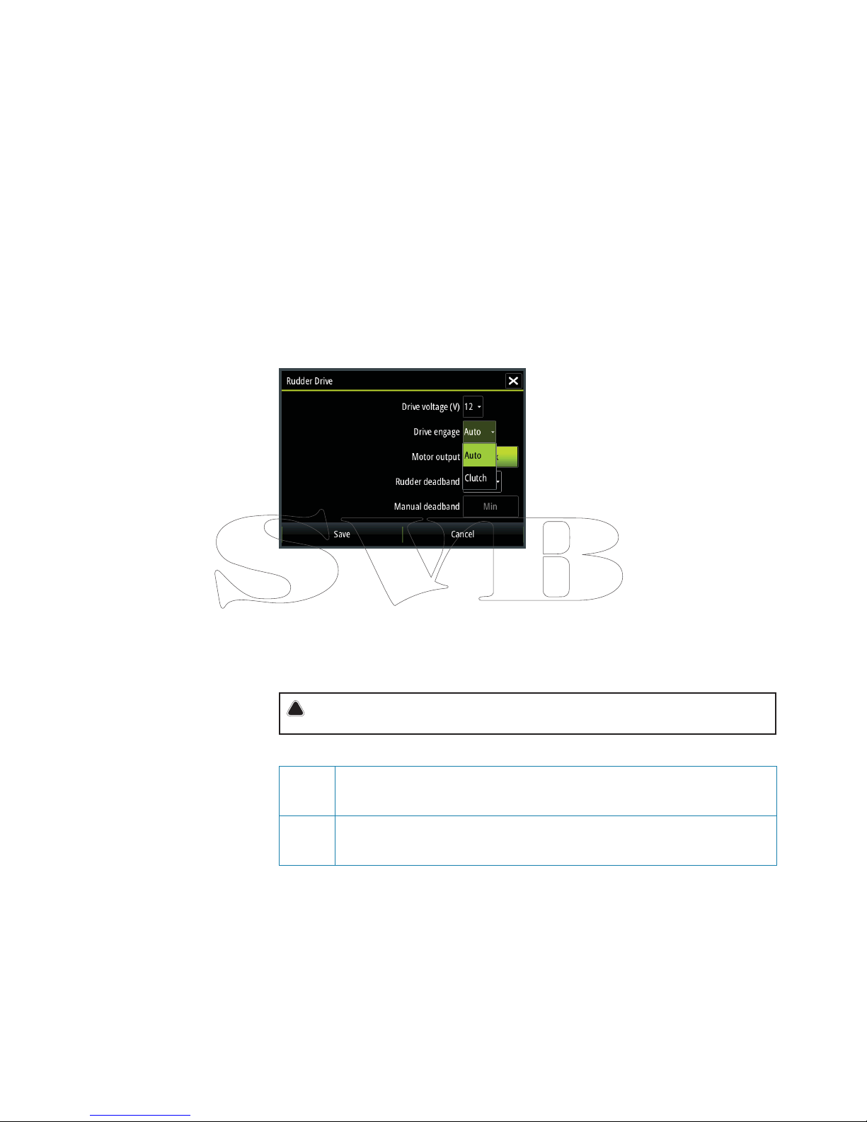
Rudder drive setup
The rudder drive setup controls how the autopilot computer controls the steering system.
Drive voltage
Voltage speci ed for your drive unit.
The Drive unit voltage setting does not apply when the system operates solenoids on a
continuous running pump/steering gear. Hence, the output voltage to the solenoids will be
the same as the input voltage.
Refer to the drive unit table in the AC12N/AC42N Installation manual or to your drive unit
documentation for information.
!
Warning: Selection of improper voltage level for your drive unit may damage both the
drive unit and the AC12N/AC42N even if the protection circuits are activated.
Drive engage
Clutch This is the default setting and it allows you to steer the boat with the helm or
wheel when in STBY mode (FU and NFU modes) as well as in all auto steering
modes
Auto This option is typically used to switch between two rudder speeds on a
continuous running pump, used when di erent rudder speeds are required for
automatic and Follow-up/Non-Follow-up steering
Motor output
Shows the amount of power needed to achieve the correct rudder speed. The reading is
obtained from the Rudder test.
The automatically set value may be increased or decreased.
Rudder deadband
This parameter is used to prevent the rudder from hunting. The reading is obtained from the
Rudder test which optimizes the deadband to the speed of the boat and the pressure on the
rudder.
If the auto-setting does not perform properly due to high inertia from the wheel or a loose
steering gear, it can be adjusted manually. Find the lowest possible value that will prevent the
Page 28

22 |
Software setup | Zeus Installation Manual
rudder from continuous hunting. A deadband will cause inaccurate steering.
Note: The rudder deadband setting is not available when the autopilot is con gured for
Virtual Rudder Feedback.
Seatrials
A seatrial can only be performed if the dockside settings are completed and con rmed.
The seatrial must always be performed in open waters at a safe distance from other tra c.
Note: You can switch the autopilot to standby mode and take manual control of the boat at
any time during the seatrial by pressing the ‘STBY/AUTO’ key.
The following seatrial calibration should be done:
• Compass calibration; used to automatically compensate for on-board magnetic interference
• Compass o set adjustment, used to compensate for a xed o set in the nal heading
readout
• Wind vane o set to compensate for a wind vane that is not mounted facing in exactly the
same direction as the bow of the vessel (dead ahead)
• Boat speed calibration
• Transition HI/LO speed setting (the speed at which you want to change the set of steering
parameters)
• Automatic tuning of the steering parameters
• Setting the seastate lter
• ‘Saiboat Setup’ menu items
Compass calibration
Before the compass calibration is started, make sure that there is enough open water around
the vessel to make a full turn.
The calibration should be done in calm sea conditions and with minimal wind to obtain good
results. Follow the on-screen instruction, and use about 60-90 seconds to make a full circle.
During the calibration, the compass will measure the magnitude and direction of the local
magnetic eld.
• If the local magnetic eld is stronger than the earth’s magnetic eld (the local eld is reading
more than 100 %), the compass calibration will fail
• If the local eld is reading more than 30 %, you should look for any interfering magnetic
objects and remove them, or you should move the compass to a di erent location. The
(local) eld angle will guide you to the local interfering magnetic object.
Note: Calibration must be made on the compass that is active for the autopilot. If the
compass is not possible to initiate calibration from the device list on the Zeus, refer to the
compass’ own instructions regarding calibration.
Note: In certain areas and at high latitudes the local magnetic interference becomes more
signi cant and heading errors exceeding ±3° may have to be accepted.
Compass mounting o set
After compass calibration, the di erence (if any) between the compass lubber line and the
boat’s center line should be compensated for.
1. Find the bearing from the boat position to a visible object. Use a chart or a chart plotter
2. Steer the boat so that the center line of the boat is aligned with the bearing line pointing
towards the object
2. Change the o set parameter so that the bearing to the object and the compass readout
becomes equal. Refer graphic above
Note: Make sure that both the compass heading and the bearing to the object have the same
unit (°M or °T).
Page 29
| 23
Software setup | Zeus Installation Manual
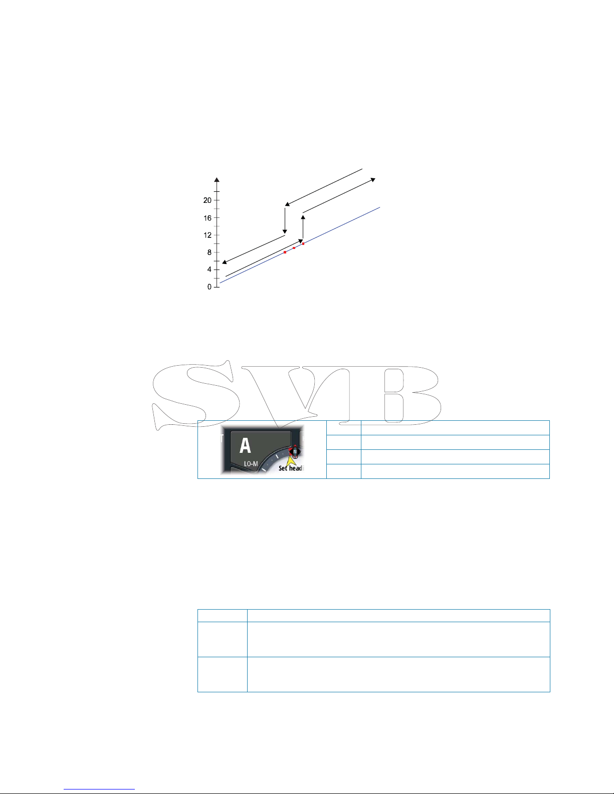
Setting the Transition speed (HI/LO)
This is the speed at which the system automatically changes from LO to HI steering
parameters.
On power boats it is recommended that you set a value that represents the speed where the
hull begins to plane or the speed where you change from slow to cruising speed.
On sailboats the transition speed should be set to around 3-4 knots to give the best response
in a tack.
A deadband of 2 knots is incorporated to prevent oscillation of HI/LO settings when vessel is
travelling at the transition speed.
1
2
3
4
5
1 HI response
2 LO response
3 Transition to HI parameters with decreasing speed: 8kn
4 Transition speed set to 9kn
5 Transition to LO parameters with increasing speed: 10kn
Active response parameter set is shown in the autopilot popup, and the following
abbreviations are used:
HI-A High response parameters set automatically
LO-A Low response parameters set automatically
HI-M High response parameters set manually
LO-M Low response parameter set manually
Autotuning
The autotune feature will run the boat through several tests and then automatically set the
most important steering parameters.
Autotune is not required for the autopilot to function, as it is preset with steering parameters
that should steer most boats in the 30-50 foot range.
You can manually adjust all parameters that are set during autotuning.
Seastate lter
The Seastate lter is used to reduce rudder activity and autopilot sensitivity in rough weather.
OFF Seastate lter is disabled. This is default
AUTO Reduces rudder activity and autopilot sensitivity in rough weather by an
adaptive process. The AUTO setting is recommended if you want to use the
seastate lter
MANUAL Linked to the steering response control settings described previously. It may be
used to manually nd the optimum combination of course keeping and low
rudder activity in rough but steady sea conditions
Page 30
24 |
Software setup | Zeus Installation Manual
Setting sailing parameters
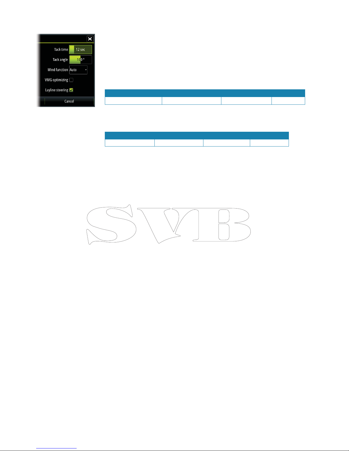
Note: Sailing parameter settings are only available if the boat type is set to Sail.
Tack time
When performing a tack in WIND mode, the rate of turn (tack time) can be adjusted. This will
give single-handed sailors time to handle the boat and the sails during a tack.
A turn performed without shifting wind side, will also be made at a controlled turn rate.
Range Change per step Default Units
2 - 50 1 12 seconds
Tack angle
This value is used to preset the course change used when tacking in AUTO mode. By pressing
the left/right arrow keys the course will change as much as this value.
Range Change per step Default Units
50 - 150 1 100 °
Wind function
With wind function set to Auto, the autopilot will automatically select between apparent and
true wind steering. Auto is default and recommended for cruising.
When the boat is running or on a broad reach, there is a heightened chance it will surf on the
waves. This may lead to signi cant changes in boat speed, and thereby changes in apparent
wind angle. True wind steering is therefore used to prevent undesired corrections by the
autopilot when heading downwind (or close to), while steering to apparent wind is used
when beating or reaching.
Apparent wind steering is preferred when you want to maintain maximum boat speed
without continuous trimming of the sails.
VMG optimizing
You can optimize the VMG to wind. When selected the function will be active for 5–10
minutes after a new wind angle has been set and only when beating.
Layline steering
Layline steering is useful when navigating. Cross Track Error (XTE) from the navigator will keep
the boat on the track line. If the XTE from the navigator exceeds 0.15 nm, the autopilot will
calculate the layline and track towards the waypoint.
Manually adjusting steering parameters
The autotune function in the autopilot is so re ned that the majority of boats will need no
further adjustments of the steering parameters. On some boats however, or in particular
sea conditions, ne tuning of the steering parameters may improve the performance of the
autopilot.
Transition speed
Refer previous description.
Rudder
This parameter determines the ratio between commanded rudder and the heading error. The
higher rudder value the more rudder is applied.
If the value is too small it will take a long time to compensate for a heading error, and the
autopilot will fail to keep a steady course.
If the value is set too high the overshoot will increase and the steering will be unstable.
Counter rudder
Counter rudder is the amount of rudder used to try to prevent the boat from yawing around
the set course. Higher counter rudder settings result in more rudder being applied.
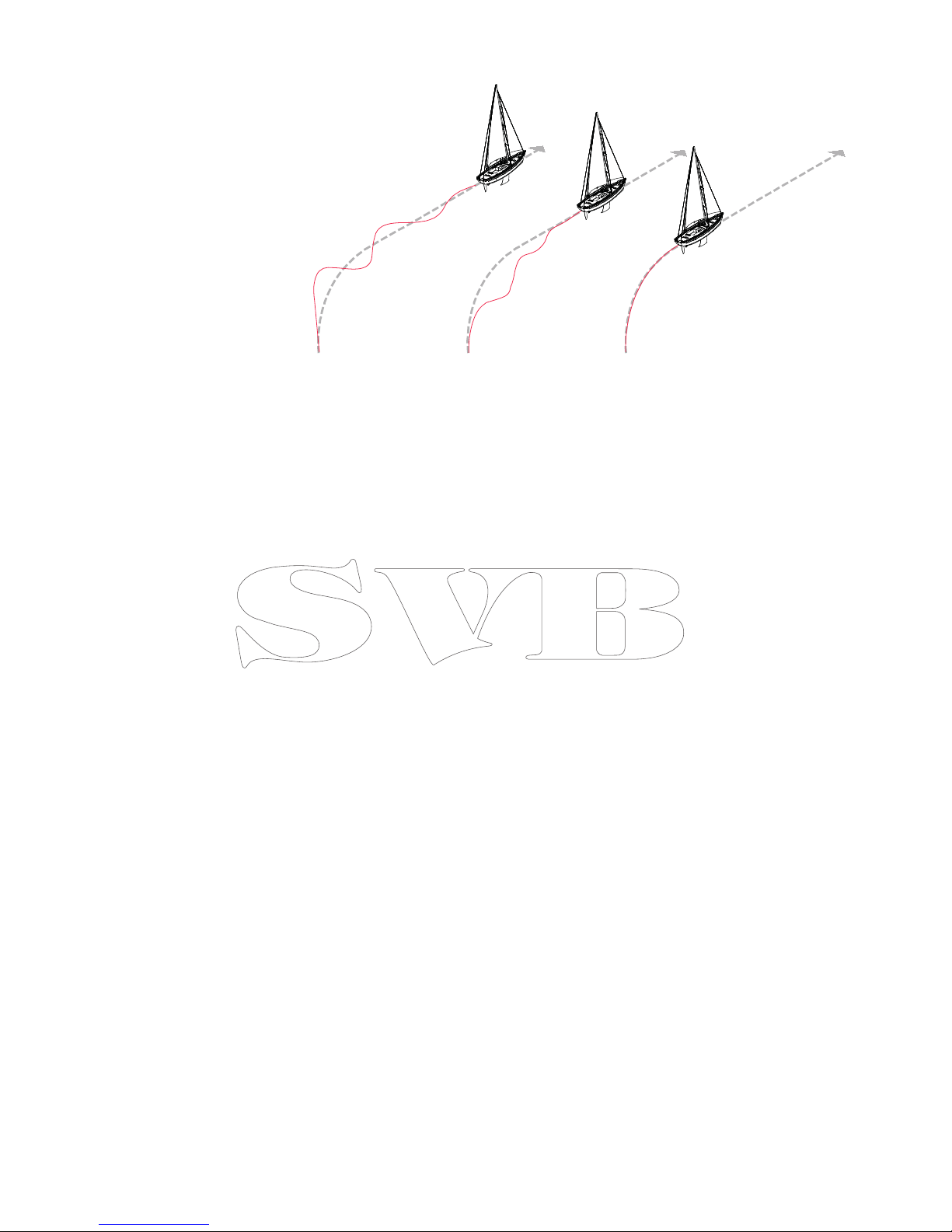
The best way of checking the value of the Counter rudder setting is when making turns.
The gures illustrate the e ects of various Counter Rudder settings;
Page 31
| 25
Software setup | Zeus Installation Manual
123
1 Counter rudder too low; overshoot response
2 Counter rudder too high; sluggish and creeping response
3 Correct setting or counter rudder; ideal response
Auto trim
This parameter de nes how fast the autopilot shall correspond after having registered a
heading error.
The standard value is 40 seconds which should work well on most boats. Rule of thumb: Set
to same value (seconds) as the boat’s length in feet. On boats operating on VRF the value
should be set to 20 seconds.
Rate limit
Sets the maximum allowed rate of turn.
The value should be kept at 6.0°/second unless there is a need for more rapid response in
turns.
Minimum rudder
This parameter lters small rudder commands to prevent high rudder activity.
Some boats may have a tendency to not respond to small rudder commands around the
“course keeping” position because of a small rudder, a rudder deadband, whirls/disturbance of
the water-stream passing the rudder or it is a single nozzle water jet boat.
By increasing the Minimum rudder parameter you may improve the course keeping
performance on some boats. This will however increase the rudder activity.
Minimum wind angle to port and starboard
These parameters should be set identical to the minimum apparent wind angle that will keep
the sails from stalling and maintain boat speed. The parameters will vary from boat to boat.
The settings are used for the tack-prevent function. They also apply when the autopilot is
operating in WindNAV mode.
You can select di erent minimum wind angles for port and starboard. The di erence between
port and starboard will be taken into account when calculating the Distance To Turn (DTT).
Navigation change limit
This parameter de nes the maximum course change that the autopilot is allowed to make
when the Zeus is following a route (NAV steering).
If the required course change to the next waypoint in a route is more than the set limit, you
are prompted and must acknowledge the course change before the autopilot will turn the
vessel.
Page 32
26 |
Software setup | Zeus Installation Manual
Fuel setup
The fuel utility monitors a vessels fuel consumption. This information is totalled to indicate
trip and seasonal fuel usage, and is used to calculate fuel economy for display on instrument
pages and the data bar.
To use the utility, a Navico Fuel Flow sensor (petrol/gasoline only), or a NMEA 2000 engine
adaptor cable/gateway with Navico Fuel Data Storage device must be tted to the vessel.
Neither the Navico Fuel Flow sensor, nor the Suzuki engine interface require the use of a
seperate Fuel Storage device. Refer to the engine manufacturer or dealer for information on
whether or not your engine provides a data output, and what adaptor is available to connect
to NMEA 2000.
Once physical connection is made, ensure source selection is completed. Multiple engine
installations using Fuel Flow sensors, or Fuel Data Storage devices, will require setup of related
engine location in the device list. For general source selection information refer to “Source
selection” on page 15.
note: Multiple engines utilising a single gateway will not work with the Navico Fuel Storage
device.
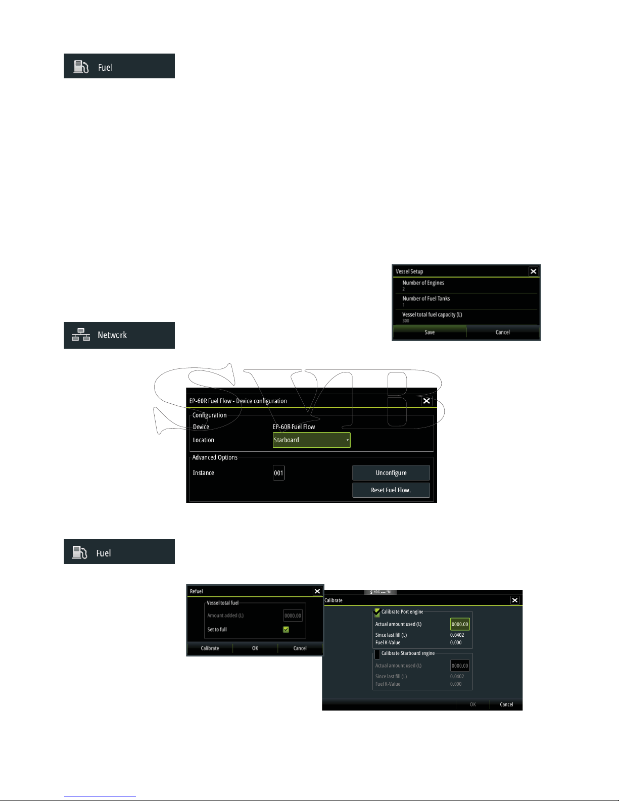
Vessel setup
This dialog must be used to select the number of
engines, the number of tanks and vessel’s total fuel
capacity across all tanks.
Fuel ow con guration
Once the number of engines are set, it’s required to
set which fuel ow sensor is connected to which engine. Under ‘Device list’ on the Network
page, view the ‘Device Con guration’ page for each sensor, and set ‘Location’ to match the
engine the device is connected to.
‘Uncon gure’ is for defaulting the device clearing all user settings, and ‘Reset Fuel Flow’ will
restore only the ‘Fuel K-Value’ setting, if set in ‘Calibrate’. Only Navico devices can be reset.
Calibrate
Calibration may be required to accurately match measured ow with actual fuel ow. Access
calibration from the ‘Refuel’ dialog. Calibration is only possible on Navico’s Fuel Flow sensor.
1. Start with a full tank and run the engine as it would normally be operated.
2. After at least several litres (a few gallons) have been used, the tank should be fully re lled, and
the ‘Set to full’ option selected.
Page 33

| 27
Software setup | Zeus Installation Manual
3. Select the ‘Calibrate’ option.
4. Set the ‘actual amount used’ based on amount of fuel added to tank.
5. Select OK to save settings. The ‘Fuel K-Value’ should now show a new value.
Note: To calibrate multiple engines repeat the steps above, one engine at a time. Alterna-
tively, run all engine simultaneously, and divide the ‘Actual amount used’ by the number of
engines. This assumes reasonably even fuel consumption on all engines.
Note: Calibrate option is only available when ‘Set to full’ is selected, and a Fuel Flow is con-
nected and set up as a source.
Note: A maximum of 8 engines is supported using Fuel Flow sensors.
Fuel Level
With the use of a Navico Fluid Level device connected to a suitable tank level sensor, it is
possible to measure the amount of fuel remaining in any equiped tank. The number of tanks
must be set in ‘Vessel Con guration’ to allow discrete tank assignment of the Fluid Level
devices. Under ‘Device list’ on the Network page, view the ‘Device Con guration’ page for each
sensor, and set Tank location, Fluid type, and Tank size.
Refer to the Operator manual on setting up the Instrument bar or a gauge on the Instruments
page using the Fluid Level device data.
Note: A maximum of 5 tanks is supported using Fluid Level devices.
Note: Tank data that is output by a compatible engine gateway can also be displayed, how-
ever tank con guration for such a data source is not possible via the Zeus displays.
Page 34
28 |
Software setup | Zeus Installation Manual
CZone setup
In order to communicate with the CZone modules connected to the network, the Zeus must
be assigned a unique CZone Display Dipswitch setting.
The functionality of the CZone system is determined by the CZone Con g File (.zcf ), which
is stored on all CZone modules and supported B&G displays, such as the Zeus. The le is
created using the CZone Con guration Tool, a specialised PC application available from BEP
Marine Ltd, and associated CZone distributors.
The Zeus system provides a means to load the Con g le, as well as apply updates to module
rmware, removing the need to take a laptop computer aboard the vessel.
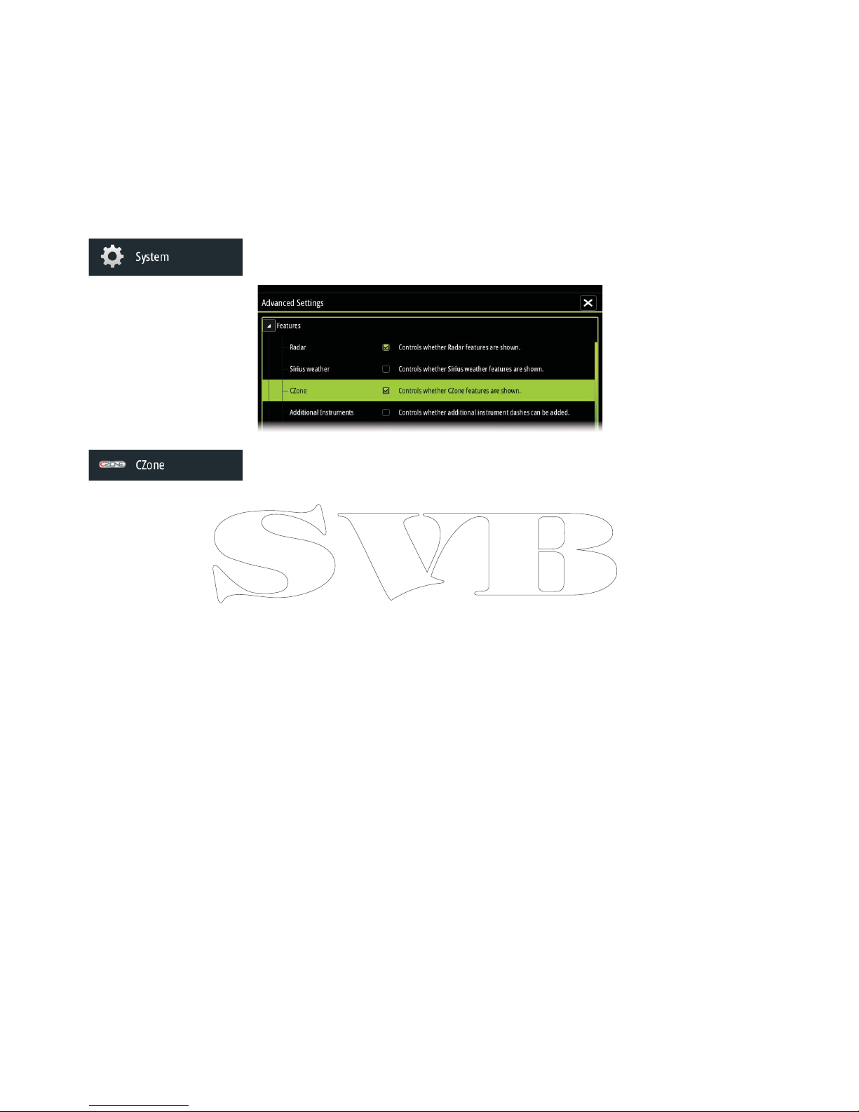
Enabling CZone functionality
If the Czone device(s) are not automatically detected, it is possible to manually enable CZone.
Assigning the dipswitch setting
Every B&G product capable of controlling and viewing CZone devices must be assigned
a virtual dipswitch setting. This setting is unique for each device. Typically it is set after the
con g le already exists on the CZone system, but it may also be set in advance. To do so,
access the CZone menu on the Settings page.
When the con g is already available on the network, it will immediately commence
uploading to the Zeus once the dipswitch is set. Allow this to complete, without interruption.
Setting CZone to display at startup
With this option selected, the CZone control page will be shown rst, every time the Zeus is
powered up.
CZone backlight control
Enabling this will cause the Zeus to synchronize its backlight setting with that of any CZone
Display Interfaces set up to share backlight settings.
note: CZone Con g also needs to have the Zeus set as a controller.
Import and backup a con g le
The les page may be used to import CZone con g les, or export a copy to a Micro SD card.
Importing will overwrite the existing le on the Zeus and all connected CZone devices.
For further information see “Backing up and Importing user data” on page 33
Upgrading module rmware
The les page also allows the loading of CZone module rmware updates. For further
information refer to “NMEA 2000 and Ethernet device updates” on page 33
Page 35

| 29
Software setup | Zeus Installation Manual
Software updates and data backup
From time to time B&G releases software updates to its existing products. Updates are created
for a variety of reasons; to add or improve features, to add support for new external devices, or
to x software bugs.
Updates can be found on the B&G website: http://www.bandg.com/Support/Downloads/
The Zeus may be used to apply software updates to itself, and to supported NMEA 2000 and
ethernet devices, with les read o an SD card.
Before initiating an update to the Zeus itself, be sure to back up any potentially valuable user
data.
Backing up and Importing user data
There are two les that can be backed up that relate to user changes made to the system:
• ‘Waypoints, Routes, and Tracks database’
• ‘Settings database’ (includes preferences such as unit settings, custom new pages, and Czone
con guration les)
The backup procedure is similar for both - simply select which you want to backup and select
the destination to save to, e.g. on the unit, or to an SD card.
The user has the option of exporting all waypoints, or exporting only waypoints contained
within a speci c region.
Waypoint backup o ers di erent le formats to save as:
• User data le version 5: Use with current Navico MFDs. O ers most detail
• User data le version 4: Use with current Navico MFDs
• User data le version 3 (with depth): Use with legacy Lowrance GPS chartplotters
• User data le version 2 (no depth): Use with legacy Lowrance GPS chartplotters
• GPX (GPS Exchange): Use with some other manufacturers’ GPS products, and PC applications
• Northstar .dat (no Tracks): Use with legacy Northstar chartplotters
The ‘Serial port’ option outputs the waypoints over NMEA 0183. The receiving GPS/PC will
typically need to be set to allow import of waypoints.
Later, if the Zeus is defaulted or user data is accidentally deleted, simply return to the les
page, highlight the backed up le, and select ‘Import’. View le details for creation date.
Zeus software upgrades
The update le must be loaded to the root directory of an SD card.
In the les menu, locate the update le on the SD card and select ‘Upgrade’. Accept the
prompt to reboot the unit, and wait a few moments as the unit restarts. Do not remove the
SD card or repower the Zeus until the process is completed (this will typically take no more
than a couple of minutes). Backup may also be initiated at boot up - simply insert the SD card,
before turning unit on, boot unit and follow on-screen instructions.
NMEA 2000 and Ethernet device upgrades
The update le must be loaded to the root directory of an SD card.
To update NMEA 2000 and ethernet devices select the ‘upgrade’ option presented when the
le is highlighted. A list should appear displaying any compatible devices the update le
applies to - in most cases this will be a single device. Select device and initiate upgrade. Do
not interrupt the upgrade process.
note: If no device is shown, check device to be updated has power, and run any outstanding
updates for the display rst.
Page 36
30 |
Software setup | Zeus Installation Manual
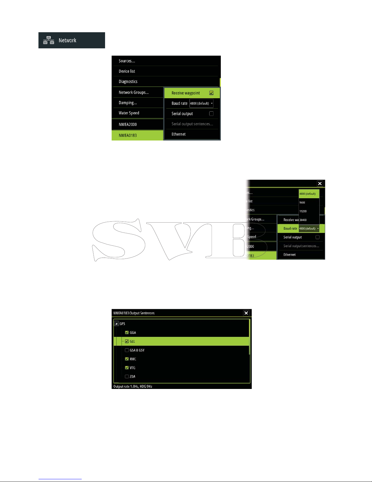
NMEA 0183 setup
The NMEA 0183 port must be set to suit the speed of connected devices, and can be be
con gured to output only the sentences required by listening devices.
Receive waypoint
Select this option to allow device capable of creating and exporting waypoints via NMEA
0183 to transfer directly to the Zeus.
Baud rate
This should be set to correspond with devices connected
to the NMEA 0183 input and output. The input and output
(Tx, Rx) use the same baud rate setting.
Note: AIS transponders typically operate at NMEA 0183-HS
(high speed), and will require the baud rate to be set to
38,400.
Serial Output
Selection will determine the whether data is output via Tx
lines, and will enable editing of the output sentences list.
Serial Output Sentences
This list allows control over which sentences need to be transmit to other devices from the
NMEA 0183 port. Due to the limited bandwidth of NMEA 0183 it is desirable to only enable
the data that is required. The less sentences are selected, the higher the output rate of the
enabled sentences.
Commonly used sentences are enabled by default.
NMEA 0183 over Ethernet
The NMEA 0183 data stream is also output over ethernet, which is made available to tablet
devices and PCs, using the WiFi1 wireless adaptor.
The ethernet dialogue provides IP and port data typically required for con guring the
application on the third party device.
Page 37
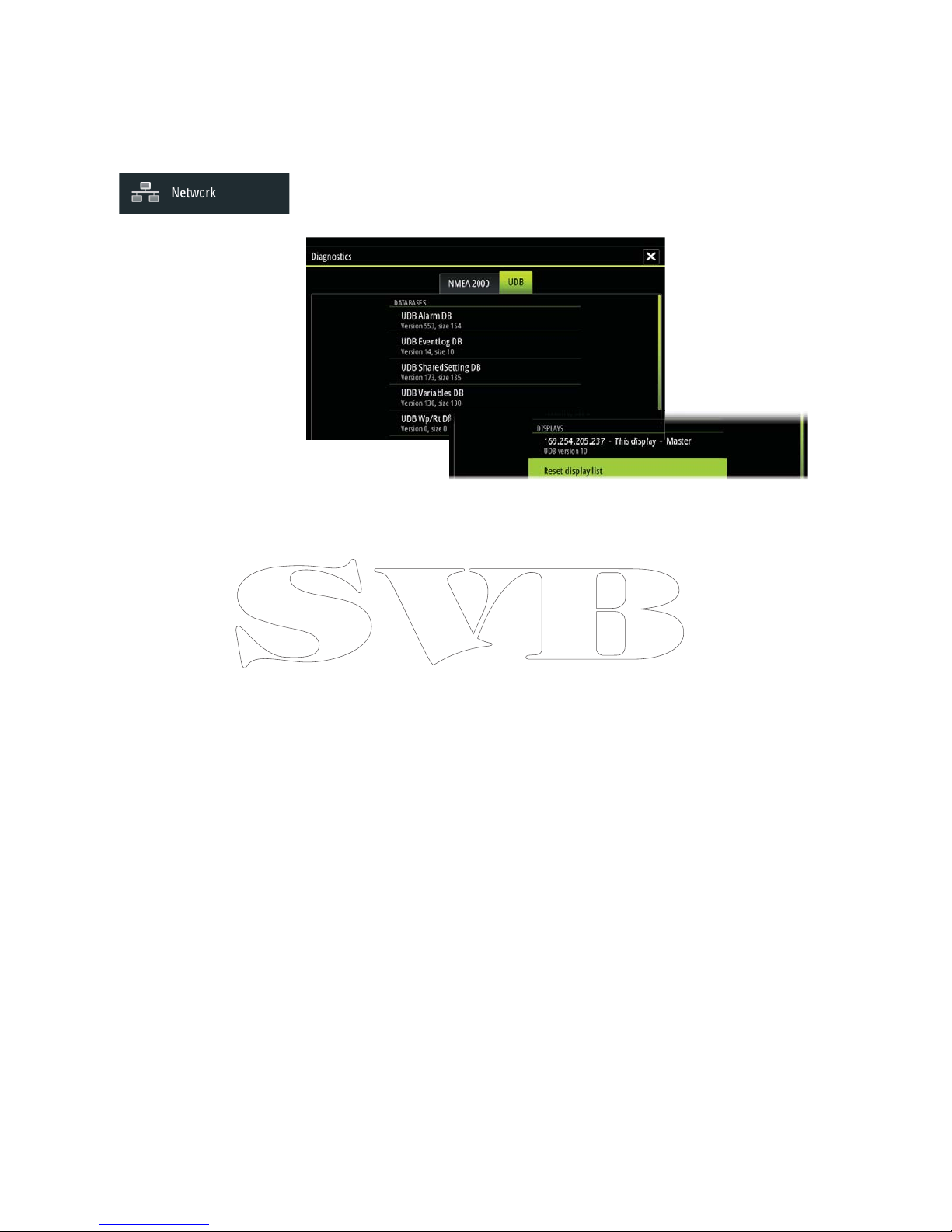
| 31
Software setup | Zeus Installation Manual
Ethernet setup
No special setup is required for establishing an ethernet network, it is all ‘plug and play’ .
An NEP-2 connected between an Zeus and another network module (e.g. 4G radar) will
automatically start working, and relay data between the two devices.
Diagnostics
The UDB (User Data Base) tab on the diagnostics page, provides information on Ethernet
activity, as shown below.
The ‘Reset Display List’ can be used to refresh the list of connected displays and their UDB
version.
Databases
The upper table gives an account of the various automatically synchronised databases that
ensure B&G display units are all using the same user settings and data. Each unit stores
the database locally, so that all information is available if the device is run in standalone.
Databases can become unsynchronised when one or more displays in a multi display network
are not powered up while other displays are being operated. Creation of waypoints, routes,
tracks, and altering global settings all a ect databases. When the tick box ‘Dirty’ is ticked, the
unit has identi ed that its database is older than that of another device on the network. The
tickbox should clear within seconds of both devices being powered up, and the databases
synchronising. If it does not clear, it is recommended that all devices have the power cycled.
IP addresses
The lower table shows the IP address of the display being viewed (top of list), the Master
display (with a tick next to it), and any other displays in a multi display network. The function
of the Master is invisible to the end user - It manages database synchronisation, however this
task automatically shifts to another display if the current master is shut down. The IP address
list only refreshes after all devices on the network have been powered down - a single device
that is shutdown on the network will not be removed from the table shown on other devices.
When powering up a system that has been completely shutdown, a network connectivity
issue can be identi ed if a display does not show any other IP addresses than its own.
The ‘UDB version’ is dependant on the software version installed on the display. It will never
change on its own, unlike the ‘Version’ of the Databases on the upper table. It is preferable to
have all UDB versions the same. This can usually be acheived by loading the latest software on
to your display - refer to “Software Updates and Screen Calibration” on page 36.
Module network light
The network LED on modules such as NEP-2, GoFree WiFi-1, and RI10, can be useful for
determining if the network is fundamentally operational. No light indicates no connection.
A rapidly blinking green LED means the network module is communicating with another
device.
FLIR® camera setup
The FLIR M-series cameras are plug and play when used in conjuction with the WiFi-1 acting
as a DHCP host. For setup on networks not utilizing a DHCP host, refer to the B&G website
www.bandg.com or contact B&G technical support.
Page 38
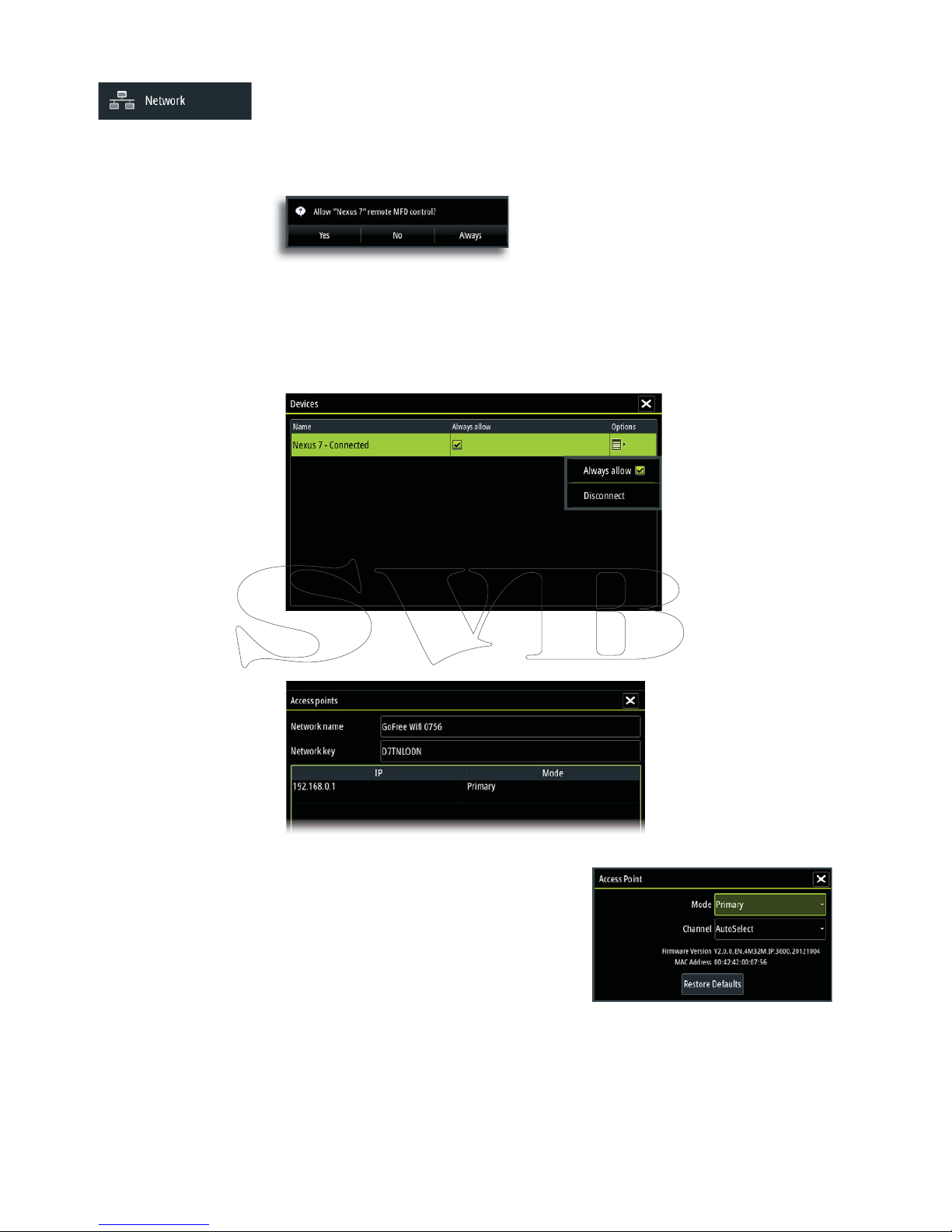
32 |
Software setup | Zeus Installation Manual
Wi setup
To connect to a GoFree device a suitable wi Android tablet or Apple ipad is required.
Navigate to the wi network connection page on the tablet, and nd the ‘GoFree Wi xxxx’
network. Connect to the network using the eight character password printed on the silver
label of the GoFree module. If the module is installed out of easy access, see the following
section ‘Access Points’ on how to identify the ‘Network Key’ (password) from the Zeus.
The above dialogue will appear on the Zeus display when connection is attempted. Select
‘Yes’ for one-time connection, or ‘Always’ if device is to be remembered for regular connection.
Devices
When a wi device is connected, it should appear in the wi devices list. Selecting ‘Always
allow’ will mean the device can automatically connect without needing a password
each time. This menu also allows disconnection of devices that no longer require access.
Access Points
This page shows connected GoFree devices and their IP address.
Mode
When more than one device is connected, only one
may operate as ‘Primary’. Primary mode determines
that the device is acting as DHCP server - only one
DHCP server may exist on a network at a time.
To set a device as secondary, the Zeus must
initially be connected to only one GoFree module.
Pressing ‘menu’ with the device highlighted, opens
the dialogue that allows setting to secondary. Once completed, a second module may be
plugged in, and will automatically default to primary.
Note: Use of multiple devices is solely for range extension purposes, and is usually only
required on larger vessels.
Page 39
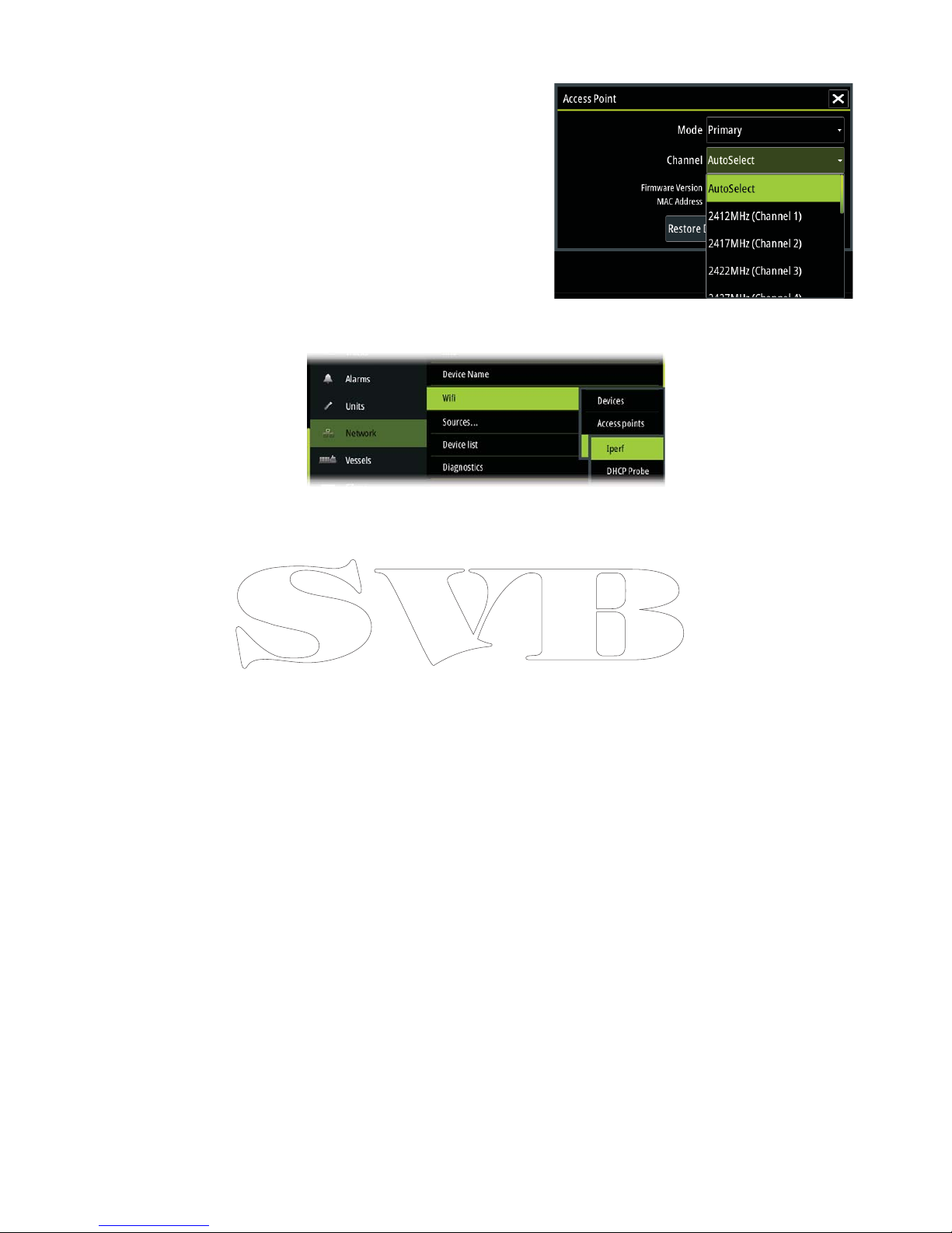
| 33
Software setup | Zeus Installation Manual
Channel
Channel setting is available in order to
overcome potential interference to the
GoFree device by another RF device
transmitting in the same frequency band.
Advanced
Tools are available within the Zeus software to assist in fault- nding and setting up the wi
network.
Iperf
Iperf is a commonly used network performance tool. It’s provided for testing Wi network
performance around the vessel so weak spots or problem areas can be identi ed. The
application must be installed on and run from the tablet device. The Zeus must be
running Iperf server before initiating the test from the tablet. On exiting the page, Iperf will
automatically stop running.
DHCP Probe
The GoFree Wi module contains a DHCP server that will allocate IP addresses for all the
MFDs, radars and sonars in a network. If integrating with other devices, such as a 3G modem
or satellite phone, other devices in the network may also be acting as DHCP servers. To make
it easy to nd all DHCP servers on a network, dhcp_probe may be run from the Zeus .
Only one DHCP device may be operational on the same network at a time. If a second device
is found, turn o it’s DHCP feature if possible. Refer to the device’s own instructions for further
assistance.
Note: Iperf and DHCP Probe are tools provided for diagnostic purposes by users familiar with
network terminology and con guration. Navico is not the original developer of these tools,
and can not provide support related to their use.
Page 40
34 |
Accessories | Zeus Installation Manual
Accessories
Part number Description
000-11586-001 Zeus LITERATURE PACK
000-11587-001 Zeus CHART CARD DOOR
000-11588-001 Zeus CONNECTOR COVERS (7/9”)
000-11589-001 Zeus CONNECTOR COVERS (12”)
000-11591-001 Zeus 7 SUN COVER
000-11593-001 Zeus 9 SUN COVER
000-11595-001 Zeus 12 SUN COVER
000-11598-001 Zeus 7 EDGE BEZELS (PAIR - SILVER AND BLACK)
000-11599-001 Zeus 9 EDGE BEZELS (PAIR - SILVER AND BLACK)
000-11600-001 Zeus 12 EDGE BEZELS (PAIR - SILVER AND BLACK)
Page 41

| 35
Supported data | Zeus Installation Manual
Supported data
NMEA 2000 compliant PGN List
NMEA 2000 PGN (receive)
59392 ISO Acknowledgement
59904 ISO Request
60928 ISO Address Claim
61184 Parameter Request/Command
65285 Temperature with Instance
65289 Trim Tab Insect Con guration
65291 Backlight Control
65292 Clear Fluid Level Warnings
65293 LGC-2000 Con guration
65323 Data User Group Request
65325 Reprogram Status
65341 Autopilot Mode
65480 Autopilot Mode
126208 ISO Command Group Function
126992 System Time
126996 Product Info
127237 Heading/Track Control
127245 Rudder
127250 Vessel Heading
127251 Rate of Turn
127257 Attitude
127258 Magnetic Variation
127488 Engine Parameters, Rapid Update
127489 Engine Parameters, Dynamic
127493 Transmission Parameters, Dynamic
127503 AC input status
127504 AC Output Status
127505 Fluid Level
127506 DC Detailed Status
127507 Charger Status
127508 Battery Status
127509 Inverter Status
128259 Speed, Water referenced
128267 Water Depth
128275 DistanceLog
129025 Position, Rapid Update
129026 COG & SOG, Rapid Update
129029 GNSS Position Data
129033 Time & Date
129038 AIS Class A Position Report
129039 AIS Class B Position Report
129040 AIS Class B Extended Position Report
129283 Cross Track Error
129284 Navigation Data
129539 GNSS DOPs
Page 42

36 |
Supported data | Zeus Installation Manual
129540 GNSS Sats in View
129794 AIS Class A Static and Voyage Related Data
129801 AIS Addressed Safety Related Message
129802 AIS Safety Related Broadcast Message
129808 DSC Call Information
129809 AIS Class B “CS” Static Data Report, Part A
129810 AIS Class B “CS” Static Data Report, Part B
130074 Route and WP Service - WP List - WP Name & Position
130306 Wind Data
130310 Environmental Parameters
130311 Environmental Parameters
130312 Temperature
130313 Humidity
130314 Actual Pressure
130576 Small Craft Status
130577 Direction Data
130840 Data User Group Con guration
130842 SimNet DSC Message
130845 Parameter Handle
130850 Event Command
130851 Event Reply
130817 Product Info
130820 Reprogram Status
130831 Suzuki Engine and Storage Device Con g
130832 Fuel Used - High Reolution
130834 Engine and Tank Con guration
130835 SetEngineAndTankCon guration
130838 Fluid Level Warning
130839 Pressure Insect Con guration
130843 Sonar Status, Frequency and DSP Voltage
Page 43

| 37
Supported data | Zeus Installation Manual
NMEA 2000 PGN (transmit)
61184 Parameter Request/Command
65287 Con gure Temperature Insects
65289 Trim Tab Insect Calibration
65290 Paddle Wheel Speed Con guration
65291 Backlight Control
65292 Clear Fluid Level Warnings
65293 LGC-2000 Con guration
126208 ISO Command Group Function
126992 System Time
126996 Product Info
127237 Heading/Track Control
127250 Vessel Heading
127258 Magnetic Variation
128259 Speed, Water referenced
128267 Water Depth
128275 DistanceLog
129025 Position, Rapid Update
129026 COG & SOG, Rapid Update
129029 GNSS Position Data
129283 Cross Track Error
129284 Navigation Data
129285 Route/Waypoint Data
129539 GNSS DOPs
129540 GNSS Sats in View
130074 Route and WP Service - WP List - WP Name & Position
130306 Wind Data
130310 Environmental Parameters
130311 Environmental Parameters
130312 Temperature
130577 Direction Data
130840 Data User Group Con guration
130845 Parameter Handle
130850 Event Command
130818 Reprogram Data
130819 Request Reprogram
130828 Set Serial Number
130831 Suzuki Engine and Storage Device Con g
130835 SetEngineAndTankCon guration
130836 Fluid Level Insect Con guration
130837 Fuel Flow Turbine Con guration
130839 Pressure Insect Con guration
130845 Weather and Fish Prediction and Barometric Pressure History
130850 Evinrude Engine Warnings
Page 44
38 |
Supported data | Zeus Installation Manual
NMEA 0183 supported sentences
TX / RX GPS
Receive GGA GLL GSA GSV VTG ZDA
Transmit GGA GLL GSA GSV VTG ZDA
Navigation
Receive RMC
Transmit AAM APB BOD BWC BWR RMC RMB XTE XDR
Echo
Receive DBT DPT MTW VLW VHW
Transmit DBT DPT MTW VLW VHW
Compass
Receive HDG HDT HDM
Transmit HDG
Wind
Receive MWV MWD
Transmit MWV MWD
AIS / DSC
Receive DSC DSE VDM AIS sentences are not bridged to or from
NMEA 2000.
MARPA
Transmit TLL TTM These are only output sentences
Page 45
| 39
Speci cations | Zeus Installation Manual
Speci cations
Mechanical/Environmental
Model
Zeus 7 Zeus 9 Zeus 12
Casing PC / ABS
Operating temp -15°C to +55°C
Water ingress IPX6 and 7
Weight (exluding mounting hardware) 1.071 kg 1.414 kg 3.171 kg
Display brightness 1200nits 1200nits 1200nits
Display resolution 480 x 800 (H
x W)
480 x 800 (H
x W)
800 x 1280 (H
x W)
Viewing angle in degrees (typical value @
contrast ratio =10)
L/R: 70
top: 50
bottom:60
L/R: 70
top: 50
bottom:70
L/R: 88
top: 88
bottom:88
Dimensions (overall) See dimensioned drawings
Electrical
Model
Zeus 7 Zeus 9 Zeus 12
Operating voltage 9 - 31.2 V DC
Power consumption 11.9 W 11.8 W 25.7 W
Low power standby mode yes
Protection reverse polarity and temporary over-
voltage to 36V
Alarm output current 1 A max
Processor iMX61 single
core
iMX61 single
core
iMX61 dual
core
Conformity CE, C-Tick,
HDMI
Interfaces
Model
Zeus 7 Zeus 9 Zeus 12
Ethernet 1 port 1 port 2 ports
NMEA 2000 (compliant) 1 port (Micro-C male)
Video input 2 analogue ports - NTCS or PAL format
Video output N/A N/A HDMI
SD dual micro SD - up to 32GB ea.
NMEA 0183 port baud rate 4800, 9600, 19200, & 38400
Charting support Embedded low detail backround +
Insight, Navionics and CMap on SD card
Page 46
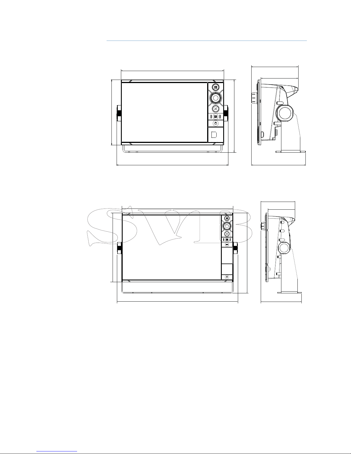
40 |
Dimensioned drawings | Zeus Installation Manual
Dimensioned drawings
Zeus 7 and Zeus 9
ZEUS 7: 231.5mm (9.11”), ZEUS 9: 279.4mm (11”)
ZEUS 7: 147.2mm (5.8”), ZEUS 9 163.6mm (6.44”)
ZEUS 7: 163.6mm (6.44”), ZEUS 9: 178.27mm
ZEUS 7: 122mm (4.8”)
ZEUS 9: 147.1mm (5.79”)
ZEUS 7: 251.1mm (9.89”), ZEUS 9: 305.1mm (12.0”)
ZEUS 7: 105.6mm (4.16”)
ZEUS 9: 106.6mm (4.20”)
ZEUS 7: 84.0mm (3.31”)
ZEUS 9: 84.0mm (3.30”)
Zeus 12
215.0mm (8.46")
345.0mm, (13.58")
375.1mm (14.77")
249.5mm (9.82")
105.6mm (4.16")
84.0mm (3.3")
126mm (4.96")
Page 47

Page 48

Page 49

Page 50

0980
*988-10604-001*
 Loading...