

BFT LUX, LUX B, LUX 2B, LUX L, LUX G Installation And User Manual
...
ISTRUZIONI D’USO E DI INSTALLAZIONE
INSTALLATION AND USER’S MANUAL
INSTRUCTIONS D’UTILISATION ET D’INSTALLATION
GEBRAUCHS-UND MONTAGEANLEITUNG
INSTRUCCIONES DE USO Y DE INSTALACION
INSTRUÇÕES DE USO E DE INSTALAÇÃO
D811035 ver. 05 15-01-07
LUX
I
GB
F
D
E
AUTOMAZIONI A PISTONE PER CANCELLI A BATTENTE
PISTON AUTOMATIONS FOR SWING GATES
AUTOMATIONS A PISTON POUR PORTAILS BATTANTS
HYDRAULISCHER DREHTORANTRIEB
AUTOMATIZACIONES A PISTON PARA PORTONES CON BATIENTE
AUTOMATIZAÇÕES A PISTÃO PARA PORTÕES COM BATENTE
P
8
027908 1 1 1 7 4 6
www.BFTGateOpeners.com | (800) 878-7829
LUX Ver. 05 - 3
D811035_05
MANUALE D’USO
ITALIANO
Nel ringraziarVi per la preferenza accordata a questo prodotto, la ditta è
certa che da esso otterrete le prestazioni necessarie al Vostro uso. Leggete attentamente l’opuscolo “Avvertenze” ed il “Libretto istruzioni” che
accompagnano questo prodotto in quanto forniscono importanti indicazioni
riguardanti la sicurezza, l’installazione, l’uso e la manutenzione. Questo
prodotto risponde alle norme riconosciute della tecnica e della disposizioni
relative alla sicurezza. Confermiamo che è conforme alle seguenti direttive
europee: 89/336/CEE, 73/23/CEE (e loro modifiche successive).
2) GENERALITA’
Pistone oleodinamico compatto e robusto, disponibile in svariate versioni a
seconda delle esigenze e del campo di utilizzo. Ci sono modelli con blocchi
idraulici e modelli senza blocchi (reversibili) che, per mantenere il blocco,
necessitano di elettroserratura. Lo sblocco di emergenza si attiva utilizzando
l’apposita chiave.
La forza di spinta si regola con estrema precisione mediante due valvole
by-pass che costituiscono la sicurezza antischiacciamento. Il funzionamento
a fine corsa è regolato elettronicamente nel quadro di comando mediante
temporizzatore.
Sono disponibili versioni speciali con rallentamento in fase di chiusura (mod.
“R”) e mod. “FC” ideali per zone innevate o quando manca la battuta d’arresto
centrale delle ante del cancello (Vedere specifico manuale istruzioni).
3) SICUREZZA
L’automazione, se installata ed utilizzata correttamente, soddisfa il grado di
sicurezza richiesto.
Tuttavia è opportuno osservare alcune regole di comportamento per evitare
inconvenienti accidentali.
• Prima di usare l’automazione, leggere attentamente le istruzioni d’uso e
conservarle per consultazioni future.
• Tenere bambini, persone e cose fuori dal raggio d’azione dell’automazione,in particolare durante il funzionamento.
• Non lasciare radiocomandi o altri dispositivi di comando alla portata dei
bambini onde evitare azionamenti involontari dell’automazione.
• Non contrastare volontariamente il movimento dell’anta.
• Non tentare di aprire manualmente il cancello se:
Nel modello LUX-LUXL-LUXG-LUXGV non è stata sbloccata l’elettroserratura con l’apposita chiave.
Nel modello LUXB-LUX2B non è stato azionato lo sblocco con l’apposita
chiave (Fig.1).
• Non modificare i componenti dell’automazione.
• In caso di malfunzionamento, togliere l’alimentazione, attivare lo sblocco
di emergenza per consentire l’accesso e richiedere l’intervento di un
tecnico qualificato (installatore).
• Per ogni operazione di pulizia esterna, togliere l’alimentazione di rete.
• Tenere pulite le ottiche delle fotocellule ed i dispositivi di segnalazione
luminosa. Controllare che rami ed arbusti non disturbino i dispositivi di
sicurezza (fotocellule).
• Per qualsiasi intervento diretto all’automazione, avvalersi di personale
qualificato (installatore).
• Annualmente far controllare l’automazione da personale qualificato.
4) APERTURA MANUALE
Versioni con blocco idraulico (LUXB-LUX2B)
Nei casi di emergenza, per esempio in mancanza di energia elettrica, per
sbloccare il cancello, infilare la stessa chiave “C” usata per la regolazione
delle valvole by-pass nel perno “P” triangolare situato sotto l’attuatore (fig.
1) e ruotarla in senso antiorario. Il cancello è così apribile manualmente
imprimendo una velocità di spinta uguale a quella di apertura automatica.
Per ripristinare il funzionamento elettrico dell’attuatore, girare la chiave in
senso orario fino al completo bloccaggio del perno “P”.
Versione senza blocco idraulico (LUX-LUXL-LUXG-LUXGV)
É sufficiente aprire l’elettroserratura con la relativa chiave e spingere manualmente l’anta.
5) MANUTENZIONE E DEMOLIZIONE
La manutenzione dell’impianto va fatta eseguire regolarmente da parte
di personale qualificato. I materiali costituenti l’apparecchiatura e il suo
imballo vanno smaltiti secondo le norme vigenti.
AVVERTENZE
Il buon funzionamento dell’operatore è garantito solo se vengono
rispettate i dati riportati in questo manuale. La ditta non risponde dei
danni causati dall’inosservanza delle norme di installazione e delle
indicazioni riportate in questo manuale.
Le descrizioni e le illustrazioni del presente manuale non sono impegnative. Lasciando inalterate le caratteristiche essenziali del prodotto,
la Ditta si riserva di apportare in qualunque momento le modifiche che
essa ritiene convenienti per migliorare tecnicamente, costruttivamente
e commercialmente il prodotto, senza impegnarsi ad aggiornare la
presente pubblicazione.
Thank you for buying this product, our company is sure that you will be more
than satisfied with the product’s performance. The product is supplied with
a “Warnings” leaflet and an “Instruction booklet”. These should both be
read carefully as they provide important information about safety, installation, operation and maintenance. This product complies with the recognised
technical standards and safety regulations. We declare that this product is in
conformity with the following European Directives: 89/336/EEC/73/23/EEC
(and subsequent amendments).
USER’S MANUAL
ENGLISH
2) GENERAL OUTLINE
A compact, sturdy oleodynamic piston, available in a wide range of models
to fit any need and field of operation. It is available in versions both with or
without (reversible) hydraulic lock, that need to be equipped with an electric
lock to hold the gate both closed and open.
The emergency release is obtained with the special key provided.
The adjustment of the pushing force is extremely precise and is performed
by means of two by-pass valves that act as an antisquash safety. The operation at the end of the stroke is controlled electronically by a timer in the
control panel.
The LUX series includes special versions with slowdown in the closing phase
(mod. “R”) while the mod. “FC” series is especially suited to areas prone to
heavy snowfalls or where the central gate stop cannot be provided (see
specific instruction manual).
3) SAFETY
If correctly installed and used, this automation device satisfies the required
safety level standards.
However, it is advisable to observe some practical rules in order to avoid
accidental problems.
• Before using the automation device, carefully read the operation instructions and keep them for future reference.
• Keep children, people and things outside the automation working area,
particularly during its operation.
• Keep radio control or other control devices out of children’s reach, in order
to avoid any unintentional automation activation.
• Do not intentionally oppose the leaf movement.
• Do not attempt to open the gate manually if:
- In mod. LUX-LUXL-LUXG-LUXGV the electric lock has not been released
by means of the appropriate key.
- In mod. LUXB-LUX2B the release has not been activated by means of
the appropriate key (fig.1).
• Do not modify the automation components.
• In case of malfunction, disconnect the power supply, activate the emergency
release to have access to the automation and request the assistance of
a qualified technician (installer).
• Before proceeding to any outside cleaning operation, disconnect the
power supply.
• Keep the photocell optical components and light signal devices clean.
• Check that the safety devices (photocells) are not obscured by branches
or shrubs.
• For any direct assistance to the automation system, request the help of
a qualified technician (installer).
• Have qualified personnel check the automation system once a year.
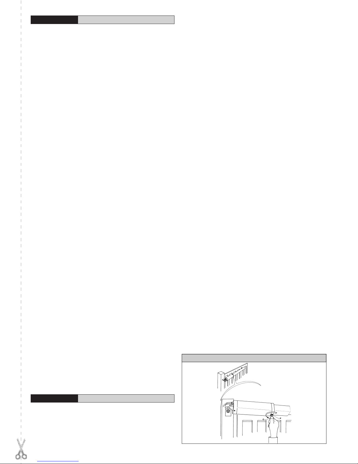
4) MANUAL OPENING
Versions with hydraulic lock (LUXB-LUX2B)
In case of emergency, for example during a power cut, the gate can be released
by inserting the same key “C” used to adjust the bypass valve into the triangular
pivot “P” found under the actuator (fig. 1) and turning it anti-clockwise. The gate can
then be opened manually following the same speed as an automatic opening.
To restore the actuator to electrical operation, turn the key clockwise until
pivot “P” is locked.
Versions without hydraulic lock (LUX-LUXL-LUXG-LUXGV)
It is sufficient to open the electr ic lock with its key and move the
leaf manually.
5) MAINTENANCE AND DEMOLITION
The maintenance of the system should only be carried out by qualified
personnel regularly. The materials making up the set and its packing must
be disposed of according to the regulations in force.
WARNINGS
Correct controller operation is only ensured when the data contained in the
present manual are observed. The company is not to be held responsible for any damage resulting from failure to observe the installation
standards and the instructions contained in the present manual.
The descriptions and illustrations contained in the present manual are
not binding. The Company reserves the right to make any alterations
deemed appropriate for the technical, manufacturing and commercial
improvement of the product, while leaving the essential product features unchanged, at any time and without undertaking to update the
present publication.
Fig. 1
www.BFTGateOpeners.com | (800) 878-7829
LUX Ver. 05 - 9
D811035_05
INSTALLATION MANUAL
ENGLISH
Thank you for buying this product, our company is sure that you will be more
than satisfied with the product’s performance. The product is supplied with
a “Warnings” leaflet and an “Instruction booklet”. These should both be
read carefully as they provide important information about safety, installation, operation and maintenance. This product complies with the recognised
technical standards and safety regulations. We declare that this product
is in conformity with the following European Directives: 89/336 EEC and
73/23/EEC (and subsequent amendments).
1) GENERAL SAFETY
WARNING! An incorrect installation or improper use of the product can
cause damage to persons, animals or things.
• The “Warnings” leaflet and “Instruction booklet” supplied with this
product should be read carefully as they provide important information
about safety, installation, use and maintenance.
• Scrap packing materials (plastic, cardboard, polystyrene etc) according
to the provisions set out by current standards. Keep nylon or polystyrene
bags out of children’s reach.
• Keep the instructions together with the technical brochure for future reference.
• This product was exclusively designed and manufactured for the use
specified in the present documentation. Any other use not specified in
this documentation could damage the product and be dangerous.
• The Company declines all responsibility for any consequences resulting from improper use of the product, or use which is different from that
expected and specified in the present documentation.
• Do not install the product in explosive atmosphere.
• The construction components of this product must comply with the following
European Directives: 89/336/EEC, 73/23/EEC and subsequent amendments. As for all non-EEC countries, the above-mentioned standards as
well as the current national standards should be respected in order to
achieve a good safety level.
• The Company declines all responsibility for any consequences resulting
from failure to observe Good Technical Practice when constructing closing structures (door, gates etc.), as well as from any deformation which
might occur during use.
• The installation must comply with the provisions set out by the following European Directives: 89/336/EEC, 73/23/EEC and subsequent
amendments.
• Disconnect the electrical power supply before carrying out any work on
the installation. Also disconnect any buffer batteries, if fitted.
• Fit an omnipolar or magnetothermal switch on the mains power supply,
having a contact opening distance equal to or greater than 3,5 mm.
• Check that a differential switch with a 0.03A threshold is fitted just before
the power supply mains.
• Check that earthing is carried out correctly: connect all metal parts for
closure (doors, gates etc.) and all system components provided with an
earth terminal.
• Fit all the safety devices (photocells, electric edges etc.) which are needed
to protect the area from any danger caused by squashing, conveying and
shearing.
• Position at least one luminous signal indication device (blinker) where it
can be easily seen, and fix a Warning sign to the structure.
• The Company declines all responsibility with respect to the automation
safety and correct operation when other manufacturers’ components
are used.
• Only use original parts for any maintenance or repair operation.
• Do not modify the automation components, unless explicitly authorised
by the company.
• Instruct the product user about the control systems provided and the
manual opening operation in case of emergency.
• Do not allow persons or children to remain in the automation operation area.
• Keep radio control or other control devices out of children’s reach, in order
to avoid unintentional automation activation.
• The user must avoid any attempt to carry out work or repair on the automation system, and always request the assistance of qualified personnel.
• Anything which is not expressly provided for in the present instructions,
is not allowed.
• Installation must be carried out using the safety devices and controls
prescribed by the EN 12978 Standard.
• Warning: during the first manoeuvring cycles, some oil may leak out
after being deposited in the breather channel during transport.
• Warning: an excessively fast manual manoeuvre can cause oil to leak
out.
2) GENERAL OUTLINE
A compact, sturdy oleodynamic piston, available in a wide range of models
to fit any need and field of operation. It is available in versions both with or
without (reversible) hydraulic lock, that need to be equipped with an electric
lock to hold the gate both closed and open.
The emergency release is obtained with the special key provided.
The adjustment of the pushing force is extremely precise and is performed by
means of two by-pass valves that act as an antisquash safety. The operation at
the end of the stroke is controlled electronically by a timer in the control panel.
The LUX series includes special versions with slowdown in the closing phase
(Mod. “R”) while the LUX FC series is especially suited to areas prone to
heavy snowfalls or where the central gate stop cannot be provided (see
specific instruction manual).
3) THE MAIN PARTS IN THE AUTOMATION (fig. 1)
M)
Single phase 2 pole motor protected by thermal circuit breaker
P) Hydraulic lobe pump
D) Fluid distributor with adjustment valves
C) Cylinder with piston
Standard components:
• gate post and gate brackets - release key and bypass adjustment
• drive capacitor - instruction booklet.
4) TECHNICAL SPECIFICATIONS
Power supply: ......................................................... 230V~±10% - 50 Hz (*)
Motor: ..........................................................................................2800 min
-1
Power absorption: ............................................................................... 250W
Capacitor: .......................................................................................... 6.3 µF
Current absorption: ............................................................................... 1.4A
Max. pressure: ................................................................................... 30 bar
Pump delivery: ...........................................................................See Table 1
Pushing force: ....................................................................................3000N
Pulling force: ..................................................................................... 2600 N
Working stroke: ..........................................................................See Table 1
Impact reaction: ...................................................................hydraulic clutch
Manual manoeuvres: ............................................................ by release key
Max. no. manoeuvres in 24: ....................................................... See table 1
Thermal protection: ........................................................................... 160° C
Ambient temperature: .......................................................... -10° C ÷ 60° C
Protection:............................................................................................IP 57
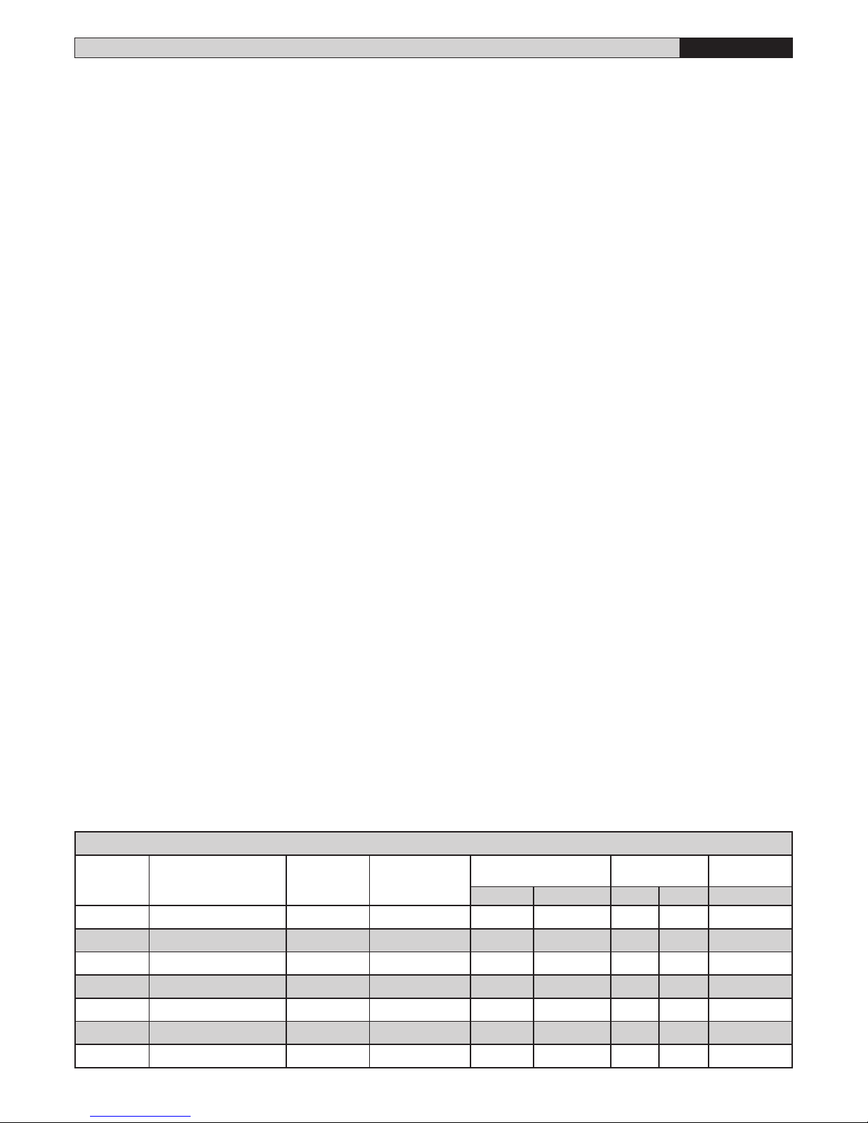
TABLE 1
MOD
TYPE OF LOCK
PUMP
l/min
WORKING TIME
(s)
MAX.WING
LENGHT/WEIGHT
STROKE
WORKING/TOT
MANOEUVRES
(m) (Kg) (mm) (mm) 24h
LUX
electric lock
1.2 17 2 300 270 290 500
LUX B
hydraulic closing
1.2 17 2 300 270 290 500
LUX 2B
hydraulic clos./open
1.2 17 2 300 270 290 500
LUX L
electric lock
0.6 33 2-4 300/500 270 290 350
LUX G
electric lock
0.6 48 5-2 300/800 390 410 250
LUX GV
electric lock
1.2 28 3,5 300 390 410 500
LUX MB
hydraulic closing
0.9 23 2 300 270 290 500
www.BFTGateOpeners.com | (800) 878-7829
 Loading...