

Page 1
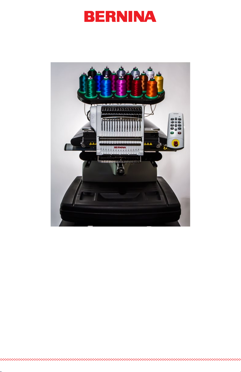
BERNINA E16 User Interface Manual
Rev 082115
Page 2

Contents
Table of Contents
What’s New 5
v1.04.XXX 5
v1.03.XXX 5
v1.02.XXX 6
v1.01.XXX 7
Machine Connections 8
Do Not Share Networks 8
Connecting the Power Cables 8
Connecting the Network Cable (Single Machine) 9
Connecting the Network Cables (Multiple Machines) 10
Selecting The Connection 11
Powering Up the Machine 12
Initial Power Up Sequence 12
Upper Threading 13
Threading the Machine for the First Time 13
Quick Thread Change 15
Upper Thread Path 17
Quick Needle Threader 21
Bobbin Threading and Tensioning 22
Removing the Bobbin Case 22
Cleaning the Bobbin Case 22
Inserting a New Bobbin in the Bobbin Case & Checking the Tension 23
Bobbin Case Tension Gauge 24
Inserting the Bobbin Case 27
Initial Maintenance 28
User Interface 29
Main Screen Overview 29
Machine Status 30
2 of 116
Page 3

Selecting Machines 31
Table of Contents
Loading A Design 32
Resetting a Design 35
Move & Rotate 36
Moving 36
Rotating A Design 37
Move to Color 37
Move to Stitch 37
Color Sequence 38
Setting Up the Thread Tree 39
Setting the Color Sequence 41
Adding Machine Commands to the Sequence 43
Adding Effects to a Color Block 45
Hoop Selection 47
Choosing the Appropriate Hoop for the Job 48
Material Thickness 50
Selecting a Material Thickness 50
Adjusting Material Thickness 51
Machine Speed 53
Settings 55
Closest Color Match on Load 55
Bobbin Detect 55
Presser Foot Adjustment 55
Maintenance 55
Advanced Settings 56
Advanced Settings Button 56
Connections 56
Machine Reset 56
Check for Update 57
3 of 116
Page 4

Hooping 58
Table of Contents
Adjusting the Hoop Tension 58
Hooping the Garment or Fabric 59
Hooping Tips 62
Attaching or Moving the Hoop Support Arms 63
Attaching the Hoop Support Arms 63
Removing the Hoop Support Arms 65
Adjusting the Spring Clips 65
Loading a Hoop onto the Machine 66
Adjusting the Presser Foot 67
Keypad Operations 69
One Touch Controls 69
Key Combinations 70
LED Indicator 72
Needle Types and Replacements 73
Replacing a Needle 73
Choosing a Needle 74
Sewing Caps 76
Installing & Removing the Wide Angle Driver 76
Red Wide Angle Driver Cap Support Wings (Option) 82
Adjusting the Red Wide Angle Driver 88
Hooping a Cap on the Conventional Cap Frame 92
Hooping a Cap on the Wide Angle Cap Frame 97
Loading/Removing a Hoop with the Wide Angle Driver 106
Digitizing for Caps 108
Sew Settings for Caps 111
Adjusting the Presser Foot for Caps 111
Centering a Design on a Cap 112
Maintenance 115
Wide Angle Driver Maintenance 115
4 of 116
Page 5

What’s New
Table of Contents
v1.04.XXX
• Check For Updates - If updates are available, the software will
automatically display an update notication. Internet connection is
required for this feature.
• Update process improvements.
• Bypass for “Trim Required” - Should you encounter a “Trim
Required” message, it may be bypassed using the keypad command of adjustment key + hoop key.
• 3D Puff - Dual buttons for 3D puff application. There is now a button for thinner foam and another for thicker foam.
• Adjustment of thread break sensor readings to reduce false upper
and lower thread breaks.
• Bobbin case recommendation change - change in construction and
pigtail location/angle.
• Single Stitch Filtering – A single stitch anked by jumped stitches
will now be ltered out to avoid needle breaks.
• Addition of the following Mighty hoops
v1.03.XXX
• 7.25”x7.25”/18.4cmx18.4cm
• Windows 10 Compatible
• Check For Updates - Now the update link provides the option
to download and view “What’s New” in the new version before
choosing to update.
• Updates will also prompt user to restart machine(s).
• Rotation Feature - User Interface will now only allow numeric input.
• Manual Update - LED status has been added to the manual.
• Maintenance Update - Thread Feed Roller removal now shows
removal tool as well as two at-bladed screw drivers.
• “Bernina” has been changed to “BERNINA”.
5 of 116
Page 6

v1.02.XXX
Table of Contents
• Optimization to thread break sensor calibrations (Advanced Interface)
• Ability to update software via check for updates (need Internet
connectivity)
• Addition of the following Mighty hoops
• 8.25”x6.25”/21cmx15.9cm
• 4.25”x4.25”/10.8x10.8cm
• 5.5”x5.5”/13.5x13.5cm
• 10”x10”/25x25cm
• 4.25”x13”/10.8x33cm
• 13”x8”/33x20cm
• 13”x11”/33x28cm
• 15”x12”/ 38x30cm
• 16”x13”/40.6cmx33cm
• Addition of the following HoopTech Clamps/Frames
• Small Shoe Clamp
• Large Shoe Clamp
6 of 116
• Red Cap Side Clamp
• Koozie Clamp
• Hat Back Clamp
• Dream Frame
• Fixed issue with design displaying the previous design on main
screen and simplied view
• Increase stitch limit to 205,000 stitches.
• Fixed spelling error (paramter to parameter)
• Copyright date is now 1992-2015
• During installation the communications drivers are signed by BERNINA.
Page 7

v1.01.XXX
Table of Contents
• Simplied user view. This is optimized for a touch screen Windows
device.
• Two click installation of the software
• Time based maintenance.
• Operator’s manual has been updated and now is in .pdf format.
• Updated Madeira Poly Neon thread chart
• Updated Isacord 40 thread chart
• Improved icon preview generation
• Fully compatible with Windows 7, Windows 8, and Windows 8.1
without compatibility mode enabled
• Simplied hoop selection by hoop type categories. For example:
square hoops, round hoops, etc.
• Simplied acti-feed selection by just selecting a product type. For
example: if the user is sewing a polo shirt they can just select the
t-shirt in product type.
• Simplied position screen. User can easily do things like rotate a
design 180 degrees by just a single click.
• Simplied load design window.
• Simplied color sequence window. This includes a puff and fancy
stitch function that can be just dragged onto the color that you
want it applied to. This also includes a color sequence repeat
function. This can be applied when doing applications like step
and repeat.
• New colorized status bar. This allows the user to see from a distance what is going on with each machine without walking over to
the PC screen.
• Presser foot adjustment button.
7 of 116
Page 8

Machine Connections
Table of Contents
This section will describe how to correctly connect the power and communications cables to the machine and the computer.
An Ethernet network connection is required to for communication between
the computer and the machine. This connection must be established in
order to control and send designs to the machine.
The method for connecting the machine to the computer will vary depending on the number of machines.
Materials Required
To connect a machine, you will need the following items:
• 1 power cable
• 1 crossover cable OR 1 Ethernet switch and 2 Ethernet cables
Note: A crossover cable is a network cable in which the wires are
crossed over. This switches the receiving and transmit signal pins on
either side. If connecting directly from the machine to the computer, a
crossover cable must be used.
Do Not Share Networks
The machines cannot share network communications with the internet. The
computer may have access to the internet, but it must be accomplished
through a separate network connection. A separate network card, either
wireless or Ethernet, will need to be used for the internet connection.
Connecting the Power Cables
1. Locate the power cable you will be using with your machine.
2. Locate the power cable plug in the rear of the machine.
8 of 116
Page 9
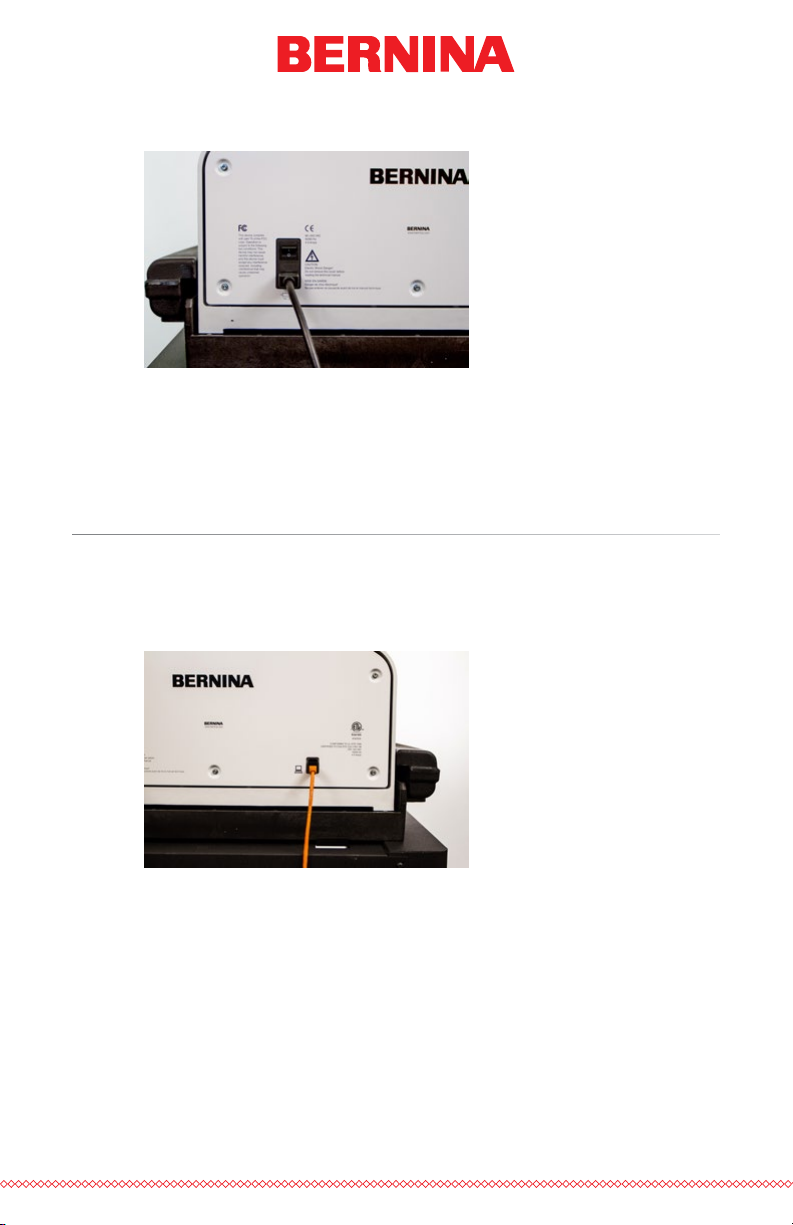
3. Make sure the machine power switch is in the OFF position. Plug
Table of Contents
the power cable into the inlet.
If you are using a line conditioner, as recommended, plug the other
end of the cable into the dedicated line conditioner.
4. Connect the line conditioner into a power source.
Connecting the Network Cable (Single Machine)
For a single machine to computer connection, a crossover cable is required.
(You can also use 2 Ethernet cables and an Ethernet switch).
1. Connect one end of the crossover cable into the Ethernet jack on
the machine.
2. Connect the other end of the crossover cable into the Ethernet jack
on the computer. The location of this network connection will vary
from computer to computer. If using multiple network cards, it may
be helpful to label them on the back of the computer.
3. Move on to Selecting the Connection.
9 of 116
Page 10
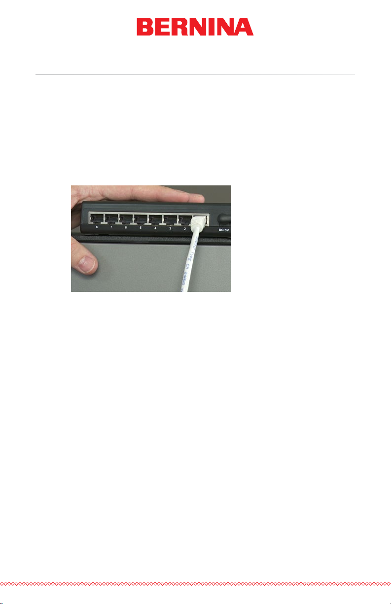
Connecting the Network Cables (Multiple Machines)
Table of Contents
For connecting multiple machines to the computer, an Ethernet switch
device and cables are required. The switch is a small electronic device that
allows multiple devices to be connected through a network. You can connect as many machines as your switch will allow.
1. Connect the Ethernet switch power cable to the switch and a
power source.
2. At least two Ethernet cables are required with the switch. Connect
one end of the Ethernet cable into any port on the switch.
3. Connect the other end of this cable directly into the Ethernet port
on the computer.
4. Now using another cable, connect one end into a different port on
the switch.
10 of 116
5. Connect the other end into the cable port on the rst machine you
want to connect.
6. If there are other machines, continue to connect the next cable(s)
from the Ethernet switch to the machine(s).
7. If all the machines are connected, you may now move on to
Selecting the Connection.
Page 11

Selecting The Connection
Table of Contents
Before a connection can be established, the appropriate connection port
must be selected in the software.
1. Launch the software by double tapping the BERNINA E16 icon.
2. Tap the Settings button to navigate to the Settings screen.
3. Tap the Advanced Settings button to navigate to the Advanced
Settings screen.
4. Select the connection the machine is going to use from the connections list by tapping the toggle to the left of the connection
name. A progress bar will display the connection status.
5. As the port is connecting, move on to powering up the machine. If
the machine does not completely initialize before the progress bar
nishes, the status may indicate that a connection is not found.
This should remedy itself after the machine fully initializes.
11 of 116
Page 12
Powering Up the Machine
Table of Contents
This section will describe how to correctly power up the machine.
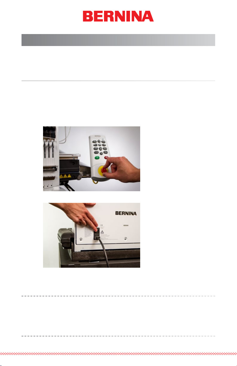
Initial Power Up Sequence
1. Make sure that all of the machines are turned off.
2. Make sure the software is launched and the Main Screen is being
displayed.
3. Make sure the E-Stop is disengaged by turning it in the direction of
the arrows.
4. Power up the machine with the power switch.
12 of 116
5. The software will load CSA and RSA les to the machine, and the
machine will initialize and display on screen.
Please note that the rst time the machine is powered up and connected to the software, it may take 90-120 seconds for the machine
to fully initialize and appear on screen. The hoop arms must rst move
from the shipping position to the home position before the machine
can initialize.
Page 13
Upper Threading
Table of Contents
The proper thread path from the cone of thread to the eye of the needle
is critical in the operation of the machine. Ensuring that the thread moves
along the appropriate route will help prevent thread breaks as well as
increase efciency and sew quality. Understanding the upper threading will
also help in troubleshooting.
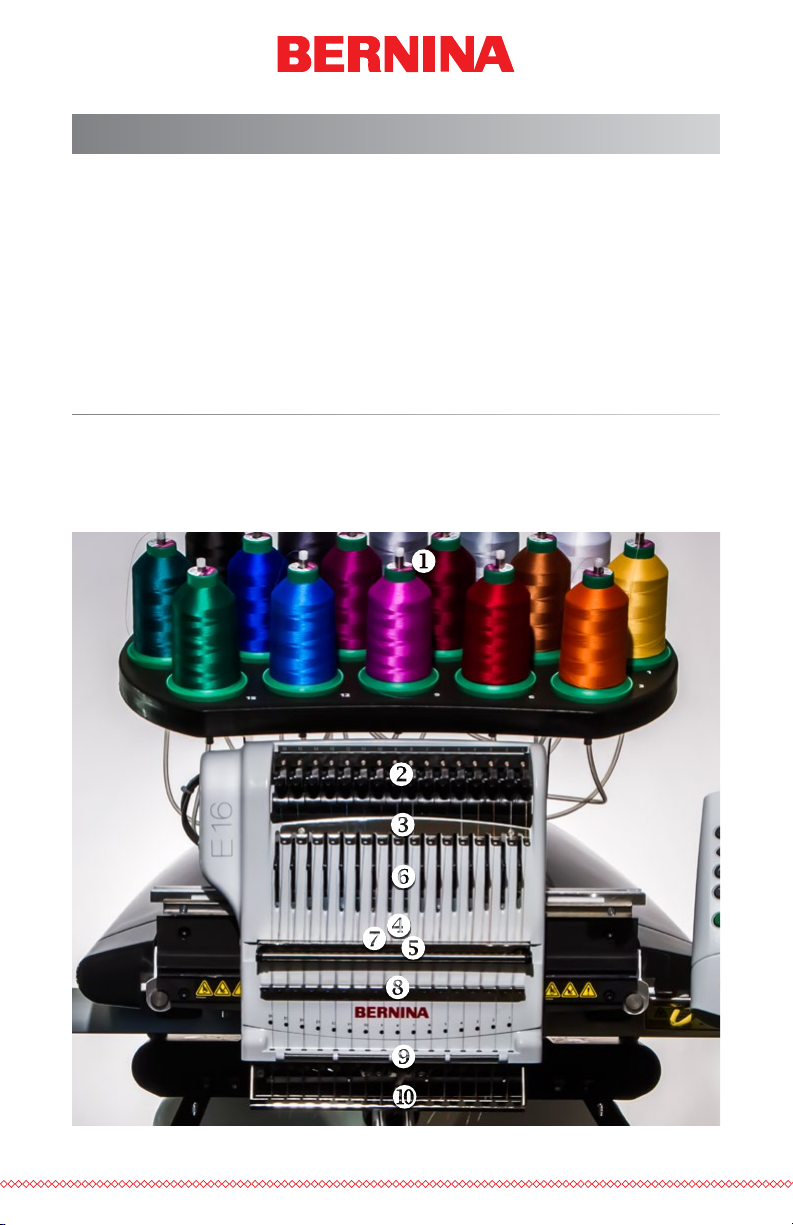
The following image displays the main components of the needle case and
the upper threading system.
Threading the Machine for the First Time
When you rst receive your machine, there will be thread in the system. The
tops of the thread will most likely be taped to the side of the thread tree.
Remove the tape and untwist the threads. New cones of thread may now
be placed on the thread tree using the quick thread change method below.
13 of 116
Page 14
Thread Cones or Thread Spools
Table of Contents
Smaller spools of thread often perform better when seated on a coaster.
These coaster help prevent the thread from catching on the bottom of the
spool when casting off.
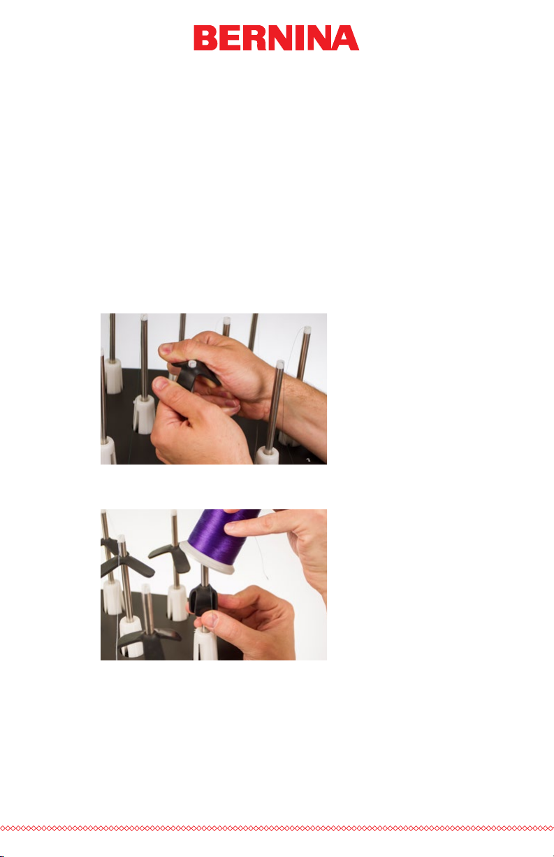
Using Thread Clovers
Some larger cones of thread have a larger inner diameter than others. If
the cones are loose and wobble, using a thread clover can help stabilize the
cone. This prevents the cones from shaking and casting off while in use.
To use the clovers:
1. Push the clover over the thread tube.
2. Collapse the clover to the thread tube as the cone is loaded onto
the machine.
14 of 116
3. Releasing the clover will cause it to expand inside the cone core
and stabilize the thread cone.
Page 15

Quick Thread Change
Table of Contents
Changing a cone of thread does not require rethreading the entire thread
path. If thread is already in the system, the fastest and easiest way to
change a cone of thread is to remove the old cone but leave a good length
of the old thread on the machine.
1. Place the new cone of thread on the thread tree with the old
thread end sticking out of the thread tube and over the new cone.
2. If used, black clover may need to be collapsed to allow the new
cone onto the thread seat. If the clover is too low on the thread
tube, the new cone of thread may not be able to sit securely on the
thread seat. If this is the case, move the clover up the thread tube
and try again.
3. If the thread is caught in the clover, pull up slightly on the clover
to create a loop of thread that you can grab. Pull the thread up
through the hole in the clover and free.
4. Extend the thread tube ½ to 1 inch above the cone. Neglecting to
extend the thread tube ½ to 1 inch above the cone could result in
frequent thread breaks.
5. After placing the cone of thread on the machine, the old thread
will be trapped on the inside and underneath the cone. From near
the tube, pull the thread free and over the top of the new cone.
15 of 116
Page 16
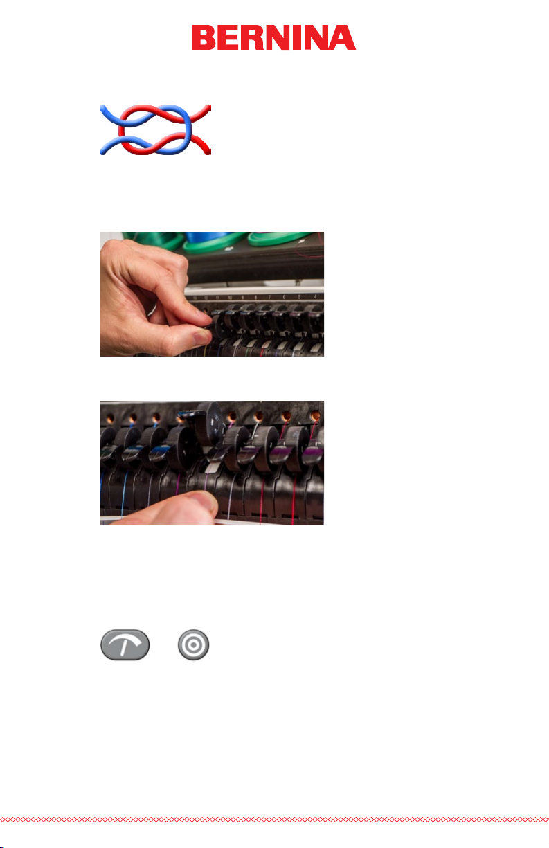
6. Tie the end of the old thread to the end of new thread using a
Table of Contents
square knot.
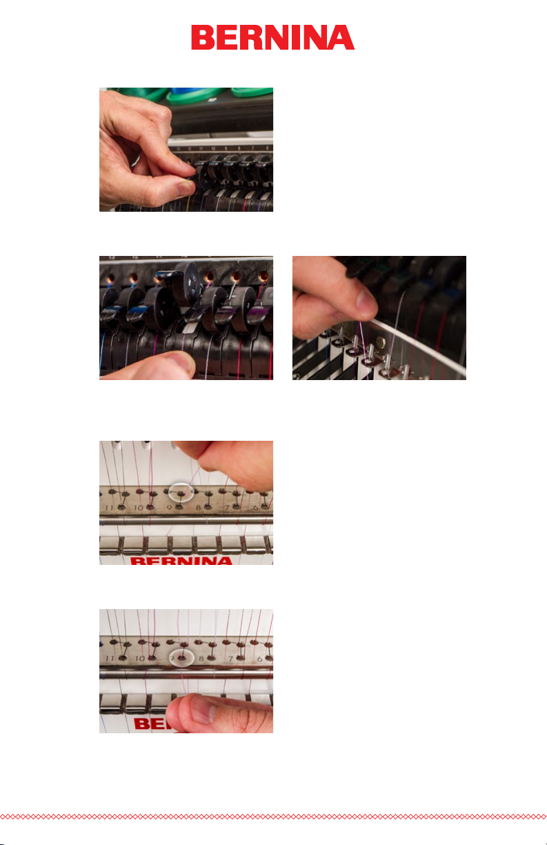
7. Lift the pinch roller and carefully pull the thread from the back
of the needle. This will pull the new thread completely through
the system. If the knot is tight and small enough, it will even slip
through the eye of the needle.
8. When nished, line up the thread under the pinch roller and press
the pinch roller back down.
16 of 116
9. If desired, the thread can then be held by the retaining spring in
front of the lower thread guide or held in place using the grabber.
With your hands out of the way, press the adjustment and center
keys on the keypad simultaneously to close the grabber and move
the thread into the holder behind the needles.
+
10. Trim the end to about an inch in length.
11. Press the keys again to open the grabber.
Page 17

Upper Thread Path
Table of Contents
If the thread comes out of the system, you may need to thread the machine
without a starter thread.
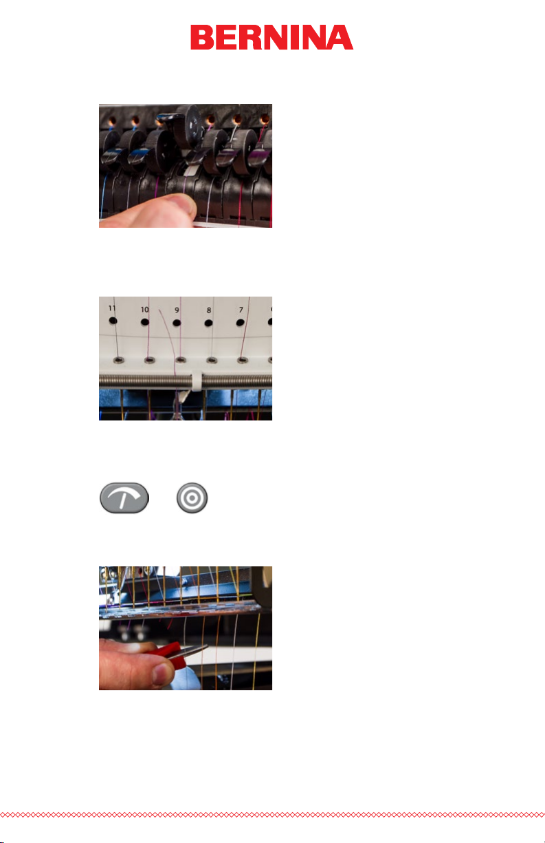
1. To start a new cone of thread, push the plastic thread tubes up
from behind the thread tree. Place the cone of thread on the
thread seat. The thread tube should extend ½ to 1 inch above the
cone.
Neglecting to extend the tube ½ to 1 inch above the cone could
result in frequent thread breaks.
2. Using either the mono-lament provided in the operator’s kit or
a can of compressed air, feed the thread through the thread tube
from the cone to the small hole behind the thread feeder assembly.
• To use the monolament, locate the small hole behind the thread
feed assembly. Push the monolament into this hole and up
through the supply tube until the end extends above the cone of
thread. Then, Secure the end of the thread in the notch of the
monolament and slowly pull the thread through the tube.
• If using compressed air, place the end of the thread in to the top of
the thread supply tube. Feed enough that the thread will stay without holding it. Now blow the compressed air into the tube. The air
will carry the thread and shoot out the front of the machine.
17 of 116
Page 18
3. Using the black tab just in front, lift the pinch roller.
Table of Contents
4. Pull the thread from the hole and place it under the pinch roller.
Bring the thread down through the upper thread guide.
5. Pull the thread down to the middle thread guide. Of the three
holes, push the thread from the top through the back right hole.
Make sure the thread is on the right side of the take-up lever.
18 of 116
6. Bring the thread around the thread sensor from back to front and
up through the front hole of the middle thread guide.
Page 19
7. Pull the thread up and through the eye of the take-up lever from
Table of Contents
right to left.
8. Route the thread straight down through the back left hole in the
middle thread guide.
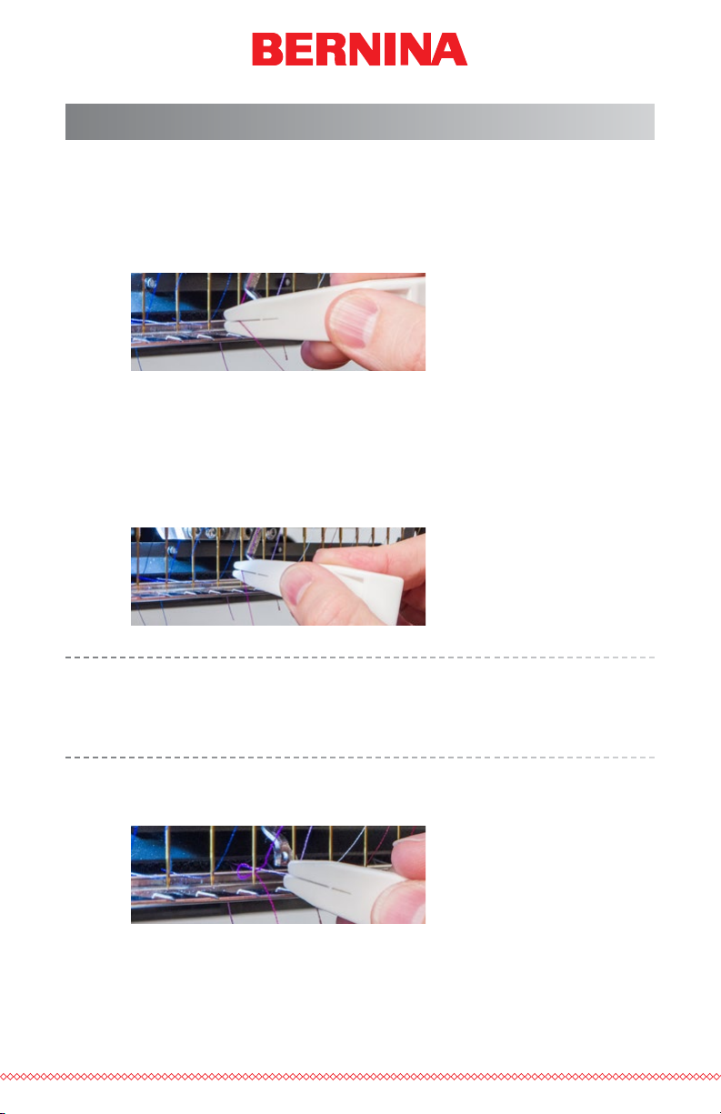
9. Press the thread into the felt restraint and feed it down through
the lower thread guide.
10. Thread the needle from front to back. Cutting the end of the
thread may allow it to more easily pass through the eye.
19 of 116
Page 20
11. Be sure to align the thread with the small v-notch in the thread
Table of Contents
feed cover.
12. Press the black tab to lower the pinch roller.
13. If desired, the thread can then be held by the retaining spring in
front of the lower thread guide or held in place using the grabber.
With your hands out of the way, press the adjustment and center
keys on the keypad simultaneously to close the grabber and move
the thread into the holder behind the needles.
20 of 116
+
Press the keys again to open the grabber.
14. Trim the end to about an inch in length
Page 21
Quick Needle Threader
Table of Contents
The needle thread is used to more easily pass the thread through the eye of
the needle. To use the needle thread, follow the steps below.
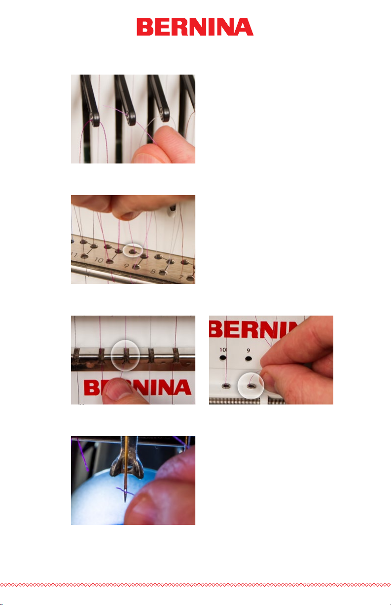
1. Lay the top thread across the front of the needle threader and into
the groove. It should lay just across the small metal prong in the
middle of the needle threader.
2. Position the threader above the eye of the needle. Press very gently
in and slide down the thread guide on the needle until the prong
reaches the eye.
3. When the needle thread reaches the eye, the gentle pressure that
you are applying will slide the prong and the thread through the
eye of the needle.
Note: This is difcult with the active needle as the presser foot is close
behind the needle. It may be easier to move the needle case one or
two needles to the left or right before useing the needle threader. Just
remember to move it back before you start sewing again.
4. Carefully remove the needle thread while leaving a loop of thread
through the eye of the needle.
5. Once the needle threader is removed, pull the loop of thread from
the back side of the needle to completely thread the needle.
21 of 116
Page 22
Bobbin Threading and Tensioning
Table of Contents
The proper bobbin tension and installation also play an integral role in the
quality and efciency of an embroidery sewout.
What Type of Bobbin?
For the best results with your machine, use Style L continuous polyester
lament bobbins.
Removing the Bobbin Case
CAUTION: Never attempt to remove or insert the bobbin while the
machine is in operation.
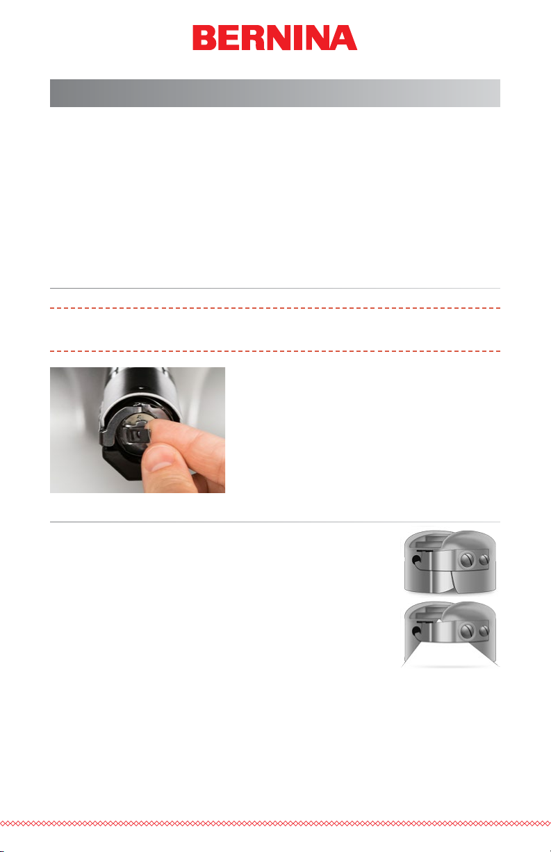
The bobbin case can be removed from the
lower arm of the machine by locating the
release lever on the bobbin case.
Pull forward on this lever until the case is free
from the machine.
Remove the old bobbin from the case.
Cleaning the Bobbin Case
It is recommended that you clean under the tension
spring of your machine bobbin case every time you
change the bobbin.
Lint and bobbin wax can build up under the spring, and
this can affect bobbin tension. To clean under the spring,
slide a corner of a small piece of paper under the tension
spring in the same direction the thread travels. While
cleaning under the tension spring, be careful not to bend
the spring.
After cleaning the bobbin case, blow the case out with compressed air. It is
also recommended that you check the bobbin tension.
22 of 116
Page 23
Inserting a New Bobbin in the Bobbin Case & Checking
Table of Contents
the Tension
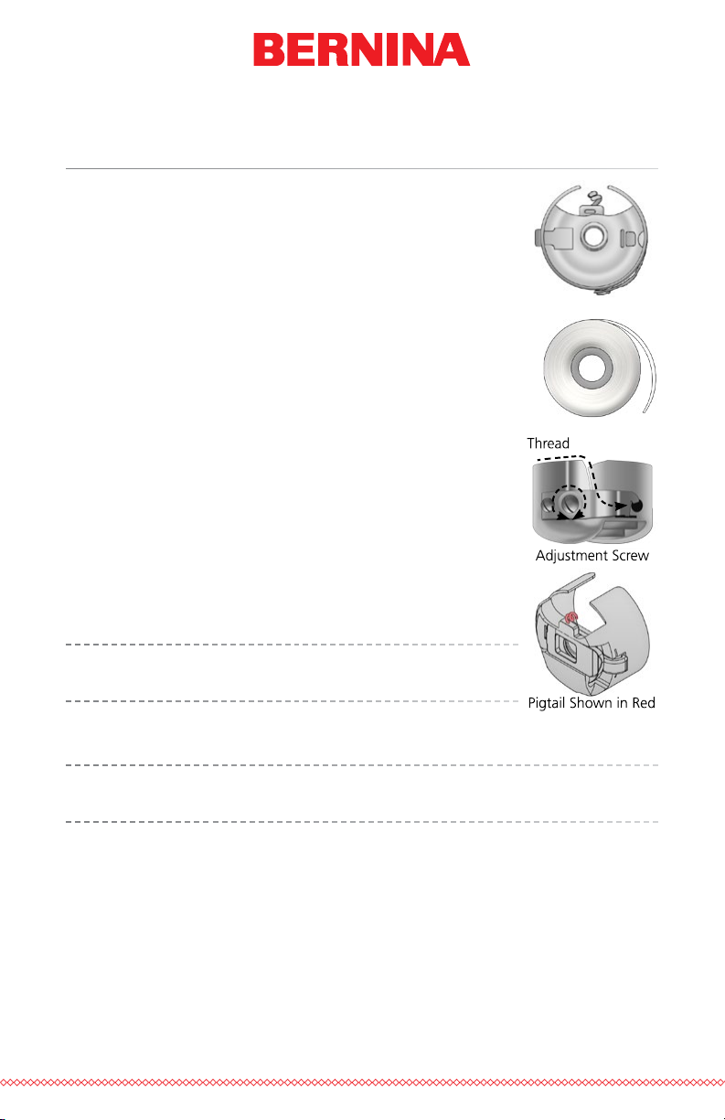
1. Hold the bobbin case with the front facing down
and the open end facing up.
2. Hold the new bobbin with the thread coming
over the top and to the right in a clockwise fashion. It should look like a number nine (9).
3. Without ipping the bobbin, drop it into the
bobbin case.
4. Route the thread through the thin slot opening
and under the tension spring. The bobbin thread
should no be releasing from the side of the case.
5. To check the tension of the bobbin, hold the
bobbin thread with one hand. As you gently
bounce the thread, the bobbin case should barely
drop. At most, it should drop a half inch / 13
mm. If the tension is incorrect, use a at-blade
screwdriver to turn the larger adjustment screw
clockwise to tighten or counterclockwise to loosen the tension.
This test must be completed BEFORE winding the thread
through the pigtail
6. Once the tension is set, wind the thread through the pigtail.
.
For a more accurate test of the bobbin tension, use a bobbin tension
gauge.
23 of 116
Page 24

Bobbin Case Tension Gauge
Table of Contents
Overview
1
2
7. Indicator
8. Second Pulley
3
5
6
4
9. First Pulley
10. Bobbin Case Set Position
11. Thread Cutter
12. Thread Take-up
24 of 116
Page 25
Using the Gauge
Table of Contents
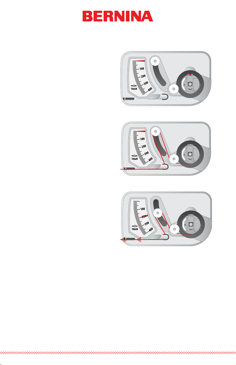
1. Clean and thread the bobbin case as you normally
would.
2. Pull the thread through the
tension spring, but do not
pull the thread through the
pigtail.
3. Insert the threaded bobbin
case into the tension gauge
with the extended portion
of the latch falling into the
guide as shown in red.
4. Route the thread through
the two pulleys and the
take up as shown in red.
5. Pull the thread gently and
smoothly in the direction
of the arrow at a rate of
approximately an inch per
second. Doing this will
cause the second pulley to
move down and with it,
the gauge indicator. Watch
as you pull for where the
indicator is when the bobbin is starting to turn.
• The ideal setting for
bobbin tension for
embroidery is between
180 and 220.
Step 3
Step 4
Step 5
• The necessary setting
for bobbin tension
during thread break
sensor calibration is
250.
25 of 116
Page 26
Adjusting Bobbin Tension
Table of Contents
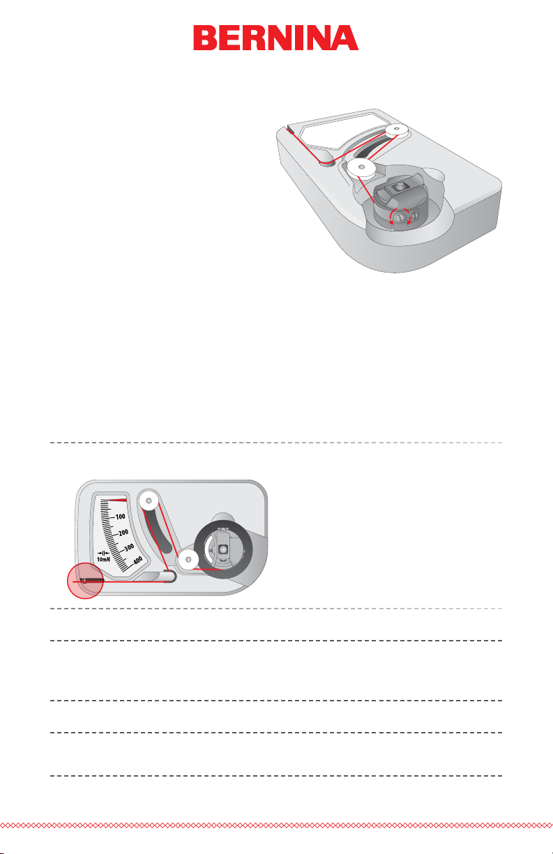
1. To adjust the tension, access
the adjustment screw (larger
of the two) on the tension
spring from the recessed
corner of the gauge.
2. Using a small at blade screw
driver, turn the adjustment
screw in small increments
between testing. Small rotations can make large adjustments to the tension.
• Clockwise: This increases the tension on the bobbin thread.
• Counter Clockwise: This decreases the tension on the bobbin
thread.
Other Instructions
Note: Extra thread may be trimmed away using the thread cutter
located below the indicator.
26 of 116
This device is a precise measuring apparatus that has been carefully
tested and adjusted. Do not drop, hit against another body, or disassemble it.
Avoid gauge contact with thinner oil, benzine oil, alcohol, and/or
petroleum.
Page 27
Inserting the Bobbin Case
Table of Contents
CAUTION: Never attempt to remove or insert the bobbin while the
machine is in operation.
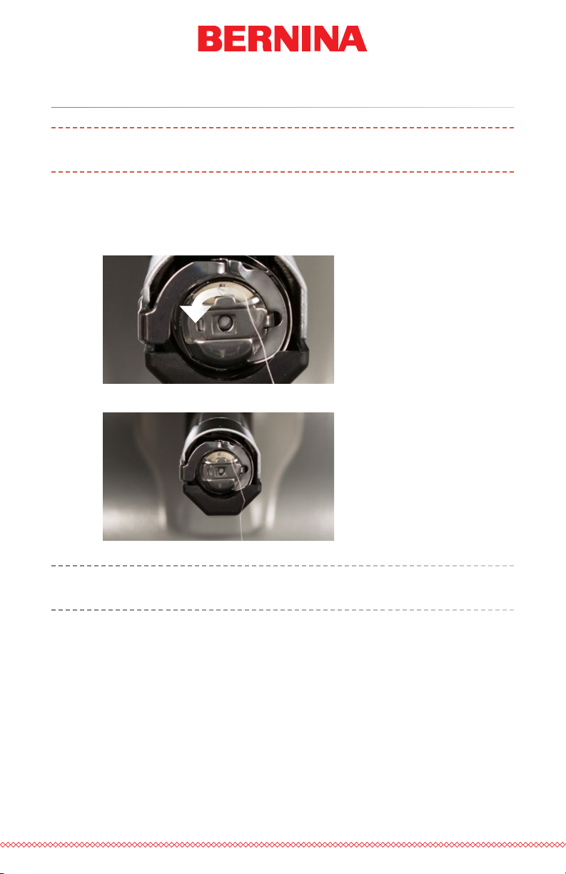
1. Insert the bobbin and case in the machine with the pigtail facing
up. Push on the bobbin case until it snaps into place.
2. Test the bobbin orientation by pulling on the thread. The bobbin
should rotate counter-clockwise.
3. Trim the thread to 2 - 3 inches.
NOTE: If the thread is cut too short, it will not pick up on the stitch. If
the thread is left too long, it may wrap into the machine.
27 of 116
Page 28

Initial Maintenance
Table of Contents
The rst time the machine is powered on, it is highly recommended that an
initial maintenance be performed. To step through this maintenance,
1. Press the Settings buttons to access maintenance.
2. Press the Maintenance button to go o to the maintenance
menu in the software and perform the following maintenance
procedures.
• Hook Maintenance
• Weekly Maintenance
• Monthly Maintenance
Each section will walk you through the maintenance procedures and move
the machine to the appropriate positions for each step.
28 of 116
Page 29
User Interface
Table of Contents
In the following sections, you will become more familiar with the operating software for your machine. The next sections will walk you through
the loading of a design and how to set machine settings such as color
sequence.
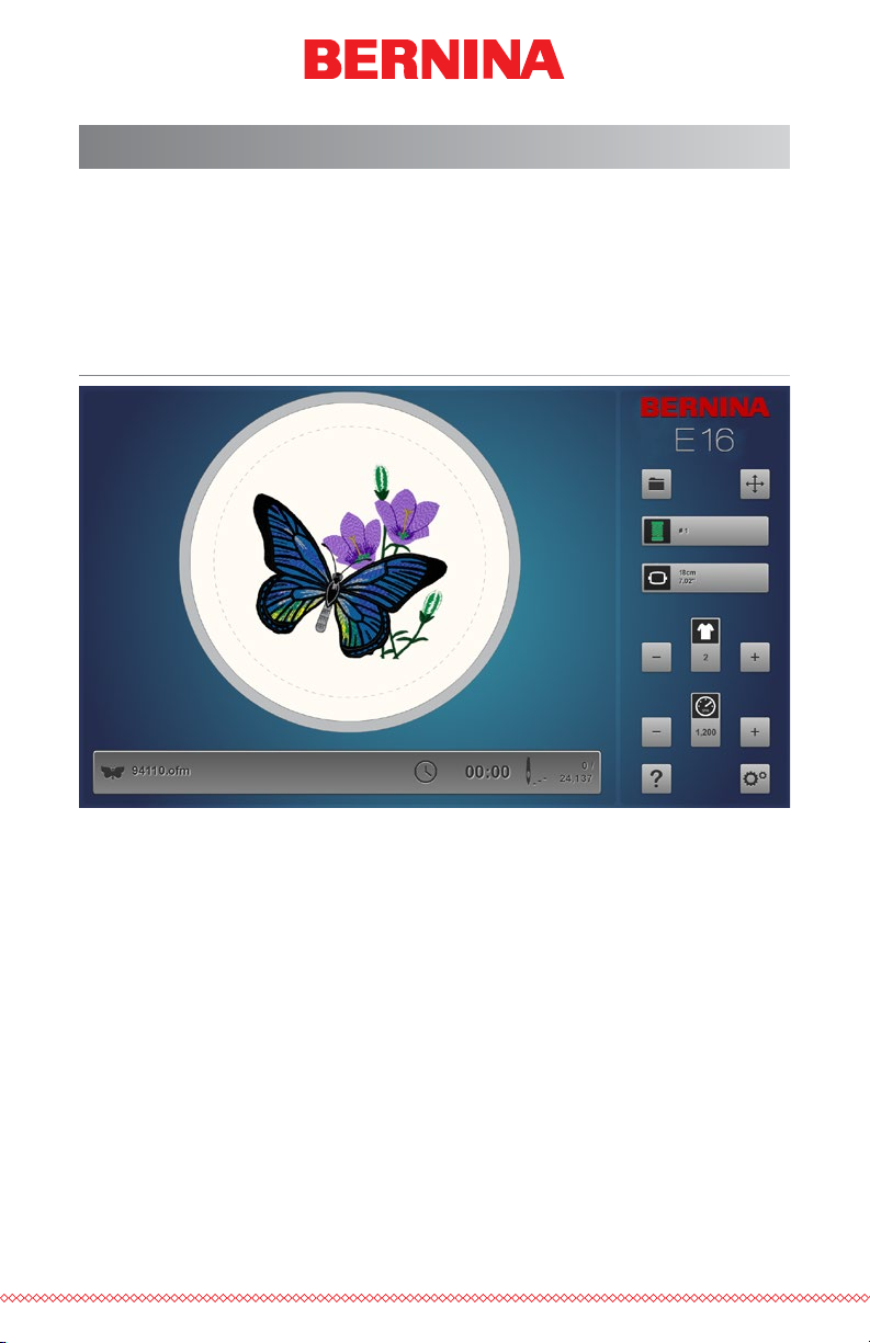
Main Screen Overview
The Main Screen is divided into three sections. Largest portion of the screen
is devoted to a preview of the design in the selected hoop. This is meant
to give the user an understanding of placement within the hoop and color
selection.
Below the preview is the machine status. This will display the time, stitch
count, and le name of the design that is loaded to the selected machine.
The right side of the screen gives access to the software commands and
settings. Here you will nd operations such as loading a design or moving
the design within the hoop. At the bottom of this section, you have access
to the Help documentation and the Settings & Maintenance screen.
29 of 116
Page 30

Machine Status
Table of Contents
Both the status bar and the machine button can indicate machine status.
The various status colors and their meanings are listed below.
Silver - indicates that the machine is in a load-ready state.
This is the only state from which you can load a design to the
machine. This is also the only state in which multiple machines
can be selected.
Green - indicates that the machine is in the process of running
a design. If the machine status is green, the status bar will
display the le name as well as the time and stitch count.
Yellow - indicates that the machine requires your attention.
This could be due to a variety of reasons ranging from an
Appliqué command to a thread break. If the machine status is
yellow, the status bar will display the reason why.
Red - indicates that an error has occurred or the emergency
stop button has been pressed. If the machine status is red, the
Status Bar will display the reason why.
30 of 116
Page 31

Selecting Machines
Table of Contents
If multiple machines are connected and communicating with the software,
you will need to select the machine that you want to view or change settings for.
By pressing the numbered machine button below the Status Bar, you will
shift focus to that machine. The Status Bar will then display the status of
that machine.
31 of 116
Page 32

Loading A Design
Table of Contents
To load a design, press the Load Design button. Note that this
button will only be available if the selected machine is in a loadready state.
If it is in the middle of a design, the button will give you the option to reset the design.
Pressing the Load Design button will bring you to the Load Design
screen.
Load Design Screen
From the Load Design screen, you can navigate to your design les on any
drive connected to your computer. Press the design that you would like to
select. Selected designs will be indicated by a slightly enlarged and darker
appearance.
32 of 116
Page 33

Conrm Selection
Table of Contents
Press the Conrm button to conrm your selection, exit the load
design screen, and load the le to the machine.
Double-tapping the le will also conrm and load the le to the
machine.
Cancel Load Design
Press the Cancel button to exit the load design screen without
loading a new design to the machine.
Navigation
The Home button will take you back to your computer.
The Level Up folder will take you to the parent folder of the current folder shown.
Breadcrumbs provide a path of drives and folders for you to navigate back
in your computer. Pressing any of these folders or drives will display their
contents.
33 of 116
Page 34

Search
Table of Contents
The Search Bar allows you to search for a le name within the current folder. Typing in this bar will automatically begin to lter the results.
Pressing the Clear button on the right side of the bar will clear the Search
Bar and return all les from the folder or drive to the window.
Sorting
The les displayed can be sorted by name or by date. The two
sort buttons will toggle between the different options. The les
may be sorted from A to Z or Z to A. They may also be sorted with
from the newest to the oldest or the oldest to the newest.
34 of 116
Page 35

Resetting a Design
Table of Contents
After a design has started sewing, the Load Design button will be
replaced with a Reset Design button.
Press this button to move to stitch zero and reset the design completely. After a design has been reset, a new design can be loaded, or the
same design can be sewn again from stitch zero.
The Reset Design button is only available when the machine is no longer in
a load-ready state.
35 of 116
Page 36

Move & Rotate
Table of Contents
To move or rotate a design in the hoop or move to a specic stitch or color,
press the move button. This button will be unavailable when the machine is
sewing.
Moving
Moving Around the Hoop
Pressing any of the arrow keys will move the hoop on the
machine and result in the design moving within the hoop in
the direction the arrow was pressed.
Similar functions can be used on the keypad of the machine. The
changes will be reected on screen. See the keypad section of this
manual for more information.
Centering
Pressing the Center button will center the hoop on the machine.
If the design was centered on the origin when it was created, this
will also center the design in the hoop.
Hoop Out/In
36 of 116
Similar functions can be used on the keypad of the machine. The
changes will be reected on screen. See the keypad section of this
manual for more information.
Pressing the Hoop Out button will move the hoop forward on
the machine as far as it can go with the needle remaining within
the hoop limits. This allows for easier access to the material or
garment and can ease access to the bobbin.
When in the out position, the only operation available is to move
the hoop back in.
Page 37

Rotating A Design
Table of Contents
Pressing the 90° button will rotate the design 90° clockwise.
Pressing the 180° button will rotate the design 180°.
To rotate the design by specic degrees, enter the desired rotation into the
eld. Pressing the Negative button will rotate the design by the specied
amount counter-clockwise. Pressing the Positive button will rotate the
design by the specied amount clockwise.
Move to Color
To move through a design without stitching and move to a specic color
press the plus or minus button to move forward or back a color from the
color displayed in the box.
Similar functions can be used on the keypad of the machine. The
changes will be reected on screen. See the keypad section of this
manual for more information.
Move to Stitch
To move to a specic stitch number without sewing, enter the desired stitch
number and press the move to stitch button.
37 of 116
Page 38

Color Sequence
Table of Contents
From the Main Screen, the Color button will display the needle that the
machine is currently on. Pressing the Color Sequence button will allow you
to set or edit a color sequence. This button will only be able to be pressed
when the machine is stopped.
Color Sequence Screen
The main Color Sequence Screen displays a representation of the machine
thread tree, a preview of the design, the color sequence, and machine commands or effects that you can add to the color sequence.
As the color sequence is altered, the design preview will change to reect
the new sequence.
The easiest way to get started is to rst assign colors to the thread tree.
Colors should be assigned after thread cones have been placed on the machine and the upper threading has been completed.
38 of 116
Page 39

Setting Up the Thread Tree
Table of Contents
When the software is rst loaded, the thread tree will displayed in grey. To
assign appropriate colors to the tree, double-tap on the thread cone to be
changed. This will bring up the thread cone assignment screen.
Thread Cone Assignment Screen
The thread cone assignment screen shows the same representation of the
thread tree and preview of the design as the previous screen. The second
half of the screen is now dedicated to the specic thread colors on the
machine.
A thread catalog is chosen on the left and the specic thread color is chosen on the right.
Assign a Thread Color to a Needle
To assign a color to a needle:
1. Select the needle/cone that you wish to assign the new color to.
Do this by clicking or tapping the cone on the thread tree at the
top of the page. The selected cone will then be highlighted.
39 of 116
Page 40

2. Select the thread catalog that contains the desired thread color.
Table of Contents
Scroll by pressing the up or down arrow. You can skip to an area
by pressing on the desired section of the alphabet between the
arrows. Once located, press the thread catalog to select it.
3. With the appropriate thread catalog selected, nd the specic
thread from the display on the right. Scroll by using the arrow
buttons, skip to an area with the scrubber, or use the Search Bar to
nd the thread by name or number.
4. Select the thread by clicking or tapping it. Once selected, it will be
highlighted and the cone on the thread tree will be changed to re-
ect the selection. If the cone is being used in the color sequence,
the design preview will also change to reect the new thread color.
5. To continue, select the next cone/needle to be changed or conrm
or cancel to exit the screen.
Searching for a Thread Color
The Search Bar can be used to search for a specic thread color in the
selected thread catalog. Typing in the Search Bar will immediately begin to
lter the contents of the window below.
Thread colors may be searched by color number or name.
Pressing the clear button on the right side of the bar will clear the Search
Bar and return all colors from the catalog to the lower window.
Conrm Thread Tree Colors
Press the Conrm button to conrm the thread tree colors, exit
the color assignment screen, and return to the Color Sequence
Screen.
Cancel Thread Tree Colors
Press the Cancel button to return to the Color Sequence Screen
without saving the new color assignments.
40 of 116
Page 41

Setting the Color Sequence
Table of Contents
With the thread tree appropriately colorized, setting the color sequence will
be easier and far more representative of the nal sew-out.
The color sequence displays two colors for every color block. The lower
sliver of color is a representation of the color information stored in the
embroidery le. The upper swatch of color represents the color currently set
to sew that color block.
To set the color sequence:
1. Select the color block from the sequence that you wish to assign
to a needle/cone. Select the color block by pressing it. The color
sequence is displayed at the bottom of the screen. Once selected,
the color block will be highlighted.
2. Select the cone/needle that you would like that color block to
be sewn with. Do this by clicking or tapping on the cone on the
thread tree above. The selected cone will be highlighted.
3. The color block will change color to match the thread cone/needle
that was selected. The design preview will also change to match
the new color sequence.
4. Continue in the same manner by rst selecting the color block you
wish to assign to a cone/needle and then selecting the cone/needle.
Use the arrow buttons to move forward and back through the sequence.
41 of 116
Page 42

Conrm Color Sequence
Table of Contents
XXXXXXXXXXXXXXX
Press the Conrm button to conrm the color sequence, exit the
Color Sequence Screen, and return to the Main Screen.
Cancel Color Sequence
Press the Cancel button to return to the Main Screen without
saving the new color sequence.
42 of 116
Page 43

Adding Machine Commands to the Sequence
Table of Contents
Machine commands can be added to the color sequence to make designs
a bit easier to sew. For example, on an especially stitch-heavy design, an
Pause command may be placed in the middle to have the machine stop
and wait for the embroiderer to change the bobbin. This would prevent
the machine from running out of bobbin thread in the middle of a critical
design element.
Appliqué
The Appliqué command is placed in between color blocks. This
will cause the machine to move the hoop out as far as possible
with the needle still within the hoop limits.
This command is often placed after the placement stitch in an appliqué
design. This allows the embroiderer to have easier access to the material without taking the hoop off of the machine. It also stops the machine
automatically instead of the embroiderer watching the sew-out to stop the
machine and place the appliqué material.
After an Appliqué command has stopped the machine, starting the machine will move the hoop back into place and continue sewing the design.
To place an Appliqué command into the sequence:
1. Locate where in the sequence you would like the machine to stop.
2. Drag the appliqué icon down into the color sequence where needed. Notice that the color blocks will shift to either side to allow
room for the command.
3. Release the appliqué icon. The command is now in the color sequence.
To remove an Appliqué command from the color sequence:
1. Drag the Appliqué command up away from the color sequence.
2. Once off of the sequence, release the command to delete it.
43 of 116
Page 44

Pause
Table of Contents
A Pause command can be inserted between color blocks in a color
sequence. This will cause the machine to stop and wait to be
restarted, but it will not move the hoop forward.
To place a Pause command into the sequence:
1. Locate when in the sequence you would like the machine to stop.
2. Drag the Pause icon down into the color sequence where needed.
Notice that the color blocks will shift to either side to allow room
for the command.
3. Release the Pause icon. The command is now displayed in the color
sequence.
To remove a Pause command from the color sequence:
1. Drag the Pause command up away from the color sequence.
2. Once off of the sequence, release the command to delete it.
44 of 116
Page 45

Adding Effects to a Color Block
Table of Contents
Effects can be added to a color block to assist in the embroidering of three
dimensional foam and micro chenille-like effects. These effects will alter the
sew settings only for the color blocks onto which they’ve been applied.
Typically, designs will need to be digitized with specic settings to fully
take advantage of these effects.
3D Foam Effect
Adding 3D Foam effect to a color block will alter the sew settings
for that color block. It will also feed extra thread to better accommodate the foam.
To place a 3D Foam effect onto a color block:
1. Locate the color block in the sequence you would like to have the
3D Foam effect.
2. Drag the 3D Foam icon down onto the color block where needed.
Use this option for thinner foam.
Use this option for thicker foam.
3. Release the 3D Foam icon. The effect is now overlaying the color block.
To remove a 3D Foam effect from the color sequence:
1. Drag the 3D Foam effect off of and away from the color block.
2. Once off of the color block, release the effect to delete it.
Often color blocks with the 3D
Foam
Pause command for the embroiderer to place the dimensional foam. It
is also common to follow the effect with a Pause command to remove
the dimensional foam from the embroidered good.
No other adjustments to material thickness are necessary.
effect applied are preceded by a
45 of 116
Page 46

Looping Effect
Table of Contents
Adding the Looping effect to a color block will alter the sew
settings to feed extra thread and cause the stitches to loop. When
coupled with a design that is digitized for this effect, it can create
a micro chenille-like look.
To place a Looping effect onto a color block:
1. Locate the color block in the sequence you would like to have the
Looping effect.
2. Drag the Looping icon down onto the color block where needed.
Use this option for thicker thread like a wool blend.
3. Release the Looping icon. The effect is now overlaying the color
block.
To remove a Looping effect from the color sequence:
1. Drag the Looping effect off of and away from the color block.
2. Once off of the color block, release the effect to delete it.
No other adjustments to material thickness are necessary.
46 of 116
Page 47

Hoop Selection
Table of Contents
From the Main Screen, the Hoop button will display the hoop that is currently selected. Pressing the Hoop button will allow you to select a different hoop. This button will only be able to be clicked or tapped when the
machine is stopped.
Pressing the Hoop button will bring up the hoop selection screen. This
screen will display the hoop types and sizes. Selecting the appropriate hoop
is critical in ensuring that hoop limits function properly.
Hoop Shape/Type
Select the hoop shape/type from the list on the right of the screen. Select
the type by clicking or tapping it. The selected type will be highlighted and
the catalog of hoops will display on the left.
Hoop Size
After selecting the shape/type of hoop, select the size of hoop from the catalog on the main portion of the screen. Each hoop displays the dimensions
and part numbers. Select the hoop by clicking or tapping it. Once selected,
it will be highlighted.
47 of 116
Page 48

Conrm Hoop
Table of Contents
XXXXXXXXXXXXXXX
Press the Conrm button to conrm the hoop, exit the hoop
selection screen, and return to the Main Screen.
Cancel Hoop
Press the Cancel button to return to the Main Screen without
saving the new hoop.
Choosing the Appropriate Hoop for the Job
Hooping a garment properly and selecting the right hoop for the job is
essential to quality embroidery production. The hoop provides the means
to move the product at high speeds and accurately place the stitch. If the
hoop is too loose, the wrong size, or if the product is hooped poorly, it can
adversely affect the design.
Choosing the Appropriate Hoop Shape
Each hoop shape has benets and drawbacks.
Hoop Shape Benet Drawback
Traditional Round Even tension across
the fabric. Great hoop
for most left-chest
designs.
Traditional Square Larger sew elds. Tension is tighter in the
Specialty (clamps and
other frames)
Tend to be easier to
hoop quickly. Better
for difcult to hoop
materials and/or
placements.
Limited number of sizes. Larger hoops must
be used for squareshaped designs.
corners and looser on
the edges.
Does not hold the material as securely as a
traditional style hoop.
48 of 116
Page 49

Choosing the Appropriate Hoop Size
Table of Contents
The ideal hoop for an embroidery design is one that just ts. The design
should fall just within the hoop limits. This removes the inuence of excess
material from around the design and can help with registration (lining up),
puckering, and overall stitch quality.
Occasionally there will be obstacles to using the smallest hoop possible for
a design. It could be that a button is in the way, or a seam would fall right
into the hoop. Adjusting your hoop size to better accommodate the material may be necessary.
Hoop Construction
Some of the larger hoops come in either wood or plastic. The wooden
hoops are double walled and have more grip than the plastic. However, the
inner and outer wooden hoop must remain aligned. The outer hoop cannot
be rotated for easier hooping or tightening. Each set of hoops will have a
registration number printed on both hoops to help keep them aligned.
Specialty Hoops
Specialty hoops such as clamps and frames that use adhesives are useful
when dealing with difcult placements on garments or materials that are
hard to hoop.
As they rarely provide the same hold on the materials as a traditional hoop,
these hoops tend to be reserved for more specialized applications.
49 of 116
Page 50

Material Thickness
Table of Contents
Choosing the relative thickness of the material being sewn will help improve sew quality.
The thickness setting is shown just below the thickness button.
Selecting a Material Thickness
To choose the Material Thickness, press the Material Thickness
button. This will bring up the material thickness screen.
Select the material that best corresponds to the material to be
sewn. Fine adjustments can be made from the Main Screen. Select the material by clicking or tapping it. The selected material will be highlighted.
Conrm Material Thickness
XXXXXXXXXXXXXXX
Press the Conrm button to conrm the material thickness, exit
the material thickness screen, and return to the Main Screen.
Cancel Material Thickness
Press the Cancel button to return to the Main Screen without
changing the material thickness.
50 of 116
Page 51

Adjusting Material Thickness
Table of Contents
Adjustments to the material thickness can be made by clicking or tapping
on either the plus or minus button to either side of the material thickness
setting.
Finding just the right settings for your material thickness is not always necessary, but it can make a marked improvement in sew quality and machine
performance.
Sew quality and thread breaks are indicators of appropriate or inappropriate
thread feed. Those symptoms are listed in sections below.
Material Thickness Value is Adequate When...
The material thickness does not need to be adjusted when:
• Satin and ll stitches - There is no looping or pulling on the top of
a sew-out when sewing satin and ll stitches.
• Satin stitches - You can see 1/3 of bobbin showing in the middle of
columns and the top color for the remainder around the sides.
• Fill Stitches - On the back of the sew-out, the top thread is even
along the edge.
51 of 116
Page 52

Increase Material Thickness When...
Table of Contents
When not enough thread is being fed into the design, you need to increase
the material thickness value. If you experience any of the following problems, you may need to perform this adjustment.
• Satin stitches - You are encountering thread breaks and you can
see bobbin thread on the top of the design.
• Satin stitches - Too much bobbin is showing on the back of the
design.
• Fill stitches - You can see bobbin thread on the top of the design.
• Fill stitches - There is not enough top thread showing on the back
of the design.
• Registration Loss - If designs are not lining up when sewn and
the cause is the thread being pulled way too tight, increasing the
Material Thickness may help. Using a stable backing will also help.
Decrease Material Thickness When...
When too much thread is being fed into the design, you need to decrease
the material thickness value. If you experience any of the following problems, you may need to perform this adjustment.
• Satin stitches - The stitches in the design are looping.
52 of 116
• Satin stitches - Not enough bobbin is showing on the back of the
design.
• Fill stitches - You are encountering thread breaks and the stitches in
the design are looping.
• False Bobbin Breaks - When the software detects bobbin breaks
that are not really breaks, it could be that your material thickness is
too high.
Page 53

Machine Speed
Table of Contents
The machine speed is displayed on the Main Screen. This reects the maximum speed that the machine will run. The machine may automatically slow
for longer stitch movements.
Changing Machine Speed
The machine speed may be altered by clicking or tapping the plus or minus
button on either side of the speed setting.
Similar functions can be used on the keypad of the machine. The
changes will be reected on screen. See the keypad section of this
manual for more information.
53 of 116
Page 54

Machine Speed Suggestions
Table of Contents
While the embroidery machines have extremely fast sew speeds, these
speeds may need to be changed depending on the products or designs
you’re planning to embroider.
When the machines start to sew, they will begin slowly and then rapidly
speed up after the thread has had a couple of stitches to catch.
The machine will sew at the set sew speed if it is possible. However, design
factors may cause the machine to slow down. Longer machine movements
and stitches will cause this. If you hear the machine changing speeds constantly, you may want to lower the set sew speed to even out sew quality.
Machine Speed Application
850-1000 s.p.m. Sewing using the Wide Angle Driver used for caps
and micro (pocket) clamps.
Designs using metallic or specialty threads.
1000-1200 s.p.m. Finer detailed designs, smaller lettering.
1200-1400 s.p.m. Faster production.
These sew speeds are meant as guidelines and should be adjusted as
needed.
Symptoms from Sewing too Fast
Sewing too quickly can result in a few undesirable outcomes. These would
include:
• Thread breaks
• Bobbin pulling to the top
• Poor registration of designs (design details or outlines don’t line up)
These symptoms can also be caused by other settings or applications.
However, if you experience one or more of these symptoms, adjusting your
sew speed could be a possible solution.
54 of 116
Page 55

Settings
Table of Contents
Pressing the Settings button on the Main screen will bring up the
Settings screen. From here machine settings may be set or submenus may be accessed.
Closest Color Match on Load
When enabled, this feature will use the color information stored in an embroidery
le to set the color sequence with the appropriate colors. It will use the closest
color match that it can nd with the colors currently assigned to the thread tree.
Not all embroidery les contain color information and some may load without.
The green “1” indicates enabled, the red “0” indicates disabled.
Bobbin Detect
This settings determines if the machine will detect bobbin breaks or not.
Certain applications may be prone to disrupting the thread sensor and
producing false breaks. For these applications, it may be easier to disable
this feature.
The green “1” indicates enabled, the red “0” indicates disabled.
Presser Foot Adjustment
The Presser Foot Adjustment button will lower and raise the needle to allow for easier adjustment of the presser foot. For more information on the adjustment of the presser foot, see that section.
Maintenance
The Maintenance button opens the maintenance screen. From
here the hook, weekly, monthly, and quarterly maintenance procedures may be initiated.
Each procedure will show a walk-through with images and text as well as
move the machine to the appropriate position for each step.
55 of 116
Page 56

Advanced Settings
Table of Contents
Advanced Settings Button
Pressing the Advanced Settings button in the settings window will
switch to the Advanced Settings screen. This is where a connection can be selected.
Connections
The connections portion of the Advanced Settings screen is used to select
the appropriate connection for your machine. Once selected, a progress bar
will indicate the checking for a connection.
Machine Reset
The Machine Reset button will prompt you to cycle the power on
your machine. When the machine reconnects with the software,
the software will push a fresh set of run les to the machine. This
will essentially reset your machine. This function is usually only used when
prompted by customer support.
56 of 116
Page 57

Check for Update
Table of Contents
The Check for Update button will look to the Internet (connection
required) to see if a newer version of the software is available. If it is,
you will be prompted to download and begin the update process.
57 of 116
Page 58

Hooping
Table of Contents
Hooping the fabric or garment securely is important to the quality of the
embroidery. This section will walk you through the adjustment of the hoop
tension as well as the hooping process.
Adjusting the Hoop Tension
You will need to adjust the tension of the hoop any time you change to
a drastically different material. For example, changing from a T-shirt to a
sweatshirt would require a change in hoop tension.
1. Start with a clean at working surface. Remove clutter from the
area. Do not hoop on an uneven surface or stack of shirts.
2. Use an appropriate hoop for your design. For more information,
read the section on choosing an appropriate hoop.
3. Loosen the tension on the outer hoop ring by turning the adjustment screw counter-clockwise.
58 of 116
4. Place the outer hoop ring inside the garment.
5. Slide the appropriate backing between the outer ring and the
hoop.
6. Smooth the fabric over the hoop.
7. Gently align the inner hoop with the outer hoop, sandwiching the
backing and a single layer of the garment. The mounting brackets
should be facing up.
8. Press the hoop down and into place. It should go fairly easily. Take
care to press on the ring rather than on the arms.
Pressing on the arms can bend the hoop out of shape or break them.
Page 59

9. Reach inside the garment and tighten the outer hoop by turning
Table of Contents
the adjustment screw clockwise. Tighten the hoop to nger-tight.
10. Now, without loosening the screw, remove the hoop from the
garment.
11. Tighten the adjustment screw a turn or two more.
12. The outer hoop is now adjusted.
The appropriate tightness of a hoop can be tested by tapping rapidly
with moderate pressure on the fabric inside the hoop. By doing this,
you can mimic the presser foot of the machine. If material walks into
the hoop, the hoop is too loose and needs further adjustment.
Hooping the Garment or Fabric
With the hoop properly adjusted, the garment can be hooped.
1. Start with a clean at working surface. Remove clutter from the
area. Do not hoop on an uneven surface or stack of shirts.
2. Use an appropriate hoop for your design. For more information,
read the section on choosing an appropriate hoop.
3. Place the properly tensioned outer hoop ring inside the garment.
4. Slide the appropriate backing between the outer ring and the
hoop.
5. Smooth the fabric over the hoop.
59 of 116
Page 60

6. Gently align the inner hoop with the outer hoop, sandwiching the
Table of Contents
backing and a single layer of the garment. The mounting brackets
should be facing up. The notch in the mounting bracket will face
the machine when the hoop is loaded onto the machine.
7. Using the hoop arms as a guide, make sure that the hoop is level
to the garment. This will help prevent sewing a design crookedly
on a product.
8. Press the hoop down and into place. Take care to press on the ring
rather than on the arms. Pressing on the arms can bend the hoop
out of shape or break them.
• It may be helpful to start by placing one hand at the just off of the
outer hoop to stabilize and smooth the fabric.
• Try to hoop in a smooth motion. If the hoop rocks back and forth,
extra material will move into the hoop and diminish the quality of
the embroidery.
60 of 116
• Do not overstretch the material. Stretching the material will stretch
and distort the sew-out. It can also lead to puckering.
Page 61

9. Once the material has been hooped, make sure that the garment
Table of Contents
is smooth, at, and taut. If the garment is loose, you may need to
remove the hoop and adjust the hoop tension or hooping method.
10. Check the back of the hooped piece. Make sure that there are not
wrinkles or other parts of the garment lodged in the hoop.
11. As a nal step, check the hoop for placement accuracy and
straightness.
61 of 116
Page 62

Hooping Tips
Table of Contents
Round hoops give the most even tension of all the hoop shapes.
Wooden hoops will have registration marks on them. These help maintain
the shape and hold of the hoop.
Many wooden hoops are double-high, meaning their sides are twice as tall
as normal hoops. They help grip slick or bulky goods because of the larger
surface area and slight tooth the wood provides.
Choose the smallest hoop that the design will t in without going over the
hoop limitations (the dotted).
Adjust the hoop tension before hooping the nal garment. If you adjust the
tension of the hoop while the garment is in it, you will increase your chances of “hoop burn” and create ripples in the garment.
Sew a Swatch!
It is often a good idea to sew a practice piece on material a similar to the
nal product as possible. Although not essential, producing a sample is an
excellent way to prevent or solve potential problems before embroidering
the nal product.
Working With Different Fabrics
Different fabrics and fabric weights may require you to loosen or tighten
the hoop. It might take a few attempts to get the exact setting for the
fabric you are working with. Most fabrics do not require the hoop to be
tightened down once in the hoop.
62 of 116
Page 63

Attaching or Moving the Hoop Support Arms
Table of Contents
Depending on the hoop you plan on using, the hoop support arms on the
machine will need to be in the inner position, outer position, or removed
completely if using a clamp or the wide angle driver.
This section will walk you through attaching and removing the support
arms properly as well as adjusting the spring clips.
Attaching the Hoop Support Arms
Determine which support arm position the chosen hoop requires. Most
of the smaller hoops require the inner position. Most of the larger hoops
require the outer position.
1. Align the hoop arms to either the inner holes or the outer holes on
the x-carriage. There will be two holes for each support arm.
2. Make sure the clips on the ends where the tubular frame will attach are facing up. The sides of the arms should face outward. This
will ensure the brackets are attached to the correct side of the carriage. Also make sure both clips are attached securely to the arms.
3. Insert two thumbscrews for each arm. Screw them in to almost
nger tight.
4. Install a hoop by sliding the side brackets of the hoop underneath
the spring clips on the support arms. Slide the hoop towards the
rear of the machine until it snaps into place and the brackets are
fully seated beneath the spring clips. Make sure that the slotted
bracket is to the right as you are facing the machine. The support
arms will still move a little.
63 of 116
Page 64

5. Using the installed hoop as a guide, square up the support arms.
Table of Contents
6. Tighten the thumb screws to nger tight.
7. Using a 6mm hex wrench, tighten the screws a quarter to half
turn more. Do not overtighten as the screws are designed to snap
before damage to the x-carriage can occur.
If the hoop brackets shift forward and back, the spring clip may need
to be adjusted. See the information below.
64 of 116
Page 65

Removing the Hoop Support Arms
Table of Contents
1. Use a 6mm hex wrench to loosen each of the two thumb screws
attaching each arm to the x-carriage.
2. Using your ngers, fully loosen the thumb screws.
3. Remove the support arms from the x-carriage.
Adjusting the Spring Clips
When you have a hoop installed, you should make sure both spring clips
are attached securely to the arms. If either side of the hoop can move front
to back underneath the clip, the clip needs to be adjusted. It may be necessary to move the hoop forward for easier access to the nuts holding the
clips. To adjust the clip:
1. Use a 5mm Hex nut driver to loosen the two nuts holding the clip
in place.
2. Push the block underneath the clip as far forward as it will go.
3. Hold the block in place while tightening the nuts.
65 of 116
Page 66

Loading a Hoop onto the Machine
Table of Contents
1. Install a hoop by sliding the side brackets of the hoop underneath
the spring clips on the support arms. Make sure that the slotted
bracket is to the right as you are facing the machine.
2. Slide the hoop towards the rear of the machine until it snaps into
place and the brackets are fully seated beneath the spring clips.
3. Pull back gently on the hoop arms to ensure the spring clips are
engaged.
4. Run your ngers around the edges of the hoop to ensure that
sleeves, collars, zippers or other garment parts are not inadvertently under the hoop. Balloon the garment out around the cylindrical
lower arm. This will prevent other garment parts from becoming
sewn into the underneath side of the embroidery.
66 of 116
Page 67

Adjusting the Presser Foot
Table of Contents
The machine has an adjustable presser foot that can be set from 0.5mm to
3.5mm above the needle plate. The presser foot height should be changed
when the thickness of the material you are sewing changes dramatically. To
adjust the presser foot height, the software must be open, and your machine must be on and communicating with it. A hoop with the fabric you
will be using should be installed.
1. Adjusting the presser foot is easiest with the needle case moved
to needle 16. It is not necessary, but it makes the adjustment gear
easier to see. If the machine is not on needle #16, the gear can still
be accessed. Do not attempt to move the needle case during the
following steps.
2. In the software, press the settings button.
3. Make sure that only the material is under the needle, for the next
step will command the machine to lower the needle.
4. Press the Lower Presser Foot button.
5. Locate the presser foot eccentric (gear) behind the needle case.
6. Turn the gear with your ngers to adjust the presser foot height up
or down as needed.
7. Set the presser foot height over an unsewn section of the fabric.
Set the presser foot so that it is just touching the material.
8. Once adjusted, press the raise presser foot button in the software.
67 of 116
Page 68

Setting the Presser Foot for Different Materials
Table of Contents
The presser foot will need to be adjusted whenever you drastically change
the thickness of material that you are sewing on. For example, if you sew
a sweatshirt and then sew a T-shirt, the presser foot would need to be
adjusted.
The presser foot is meant to stabilize the material as the needle moves
down through it and then help keep the material off of the needle as the
needle moves back up. Ideally, the presser foot would sit just on the surface
of the material, but that setting may not work for all material types.
For squishy materials like eece or terry cloth, it is often better to lower the
foot a bit more and press into the material.
Symptoms of Poor Presser Foot Height
Having the presser foot set poorly can result in a few sewing issues.
Presser Foot Height Symptom
Too High • Thread breaks
• Poor registration
Too Low • Louder sewing
• Faint lighter halo around designs or dark
fabric (Usually removed with steam, water,
or a light ironing aid)
68 of 116
Page 69

Keypad Operations
Table of Contents
The machine keypad controls not only the starting and stopping of
the machine, but it also provides access to change hoop position,
sew speed, as well as the active needle. Many of these functions
require the pressing of just a single button. Other functions require
pressing multiple buttons simultaneously.
One Touch Controls
Start
Press to start sewing
Stop
Press to stop sewing
Emergency Stop (E-Stop)
Press this emergency stop button to stop immediately and
cut power to the motors of the machine. Turn the knob
clockwise to release.
Frame Back
Move backward through a design one stitch at a time without stitching. Hold to move. Release to stop.
After 15 stitches, machine will speed up. Press the stop
button to stop.
Frame Forward
Move forward through a design one stitch at a time without stitching. Hold to move. Release to stop.
After 15 stitches, machine will speed up. Press the stop
button to stop.
Laser
Press to illuminate the point directly below the active needle.
69 of 116
Page 70

Key Combinations
Table of Contents
Center Hoop
+
Move Hoop
+
+
+
+
Trace Design
+
Bypass “Trim Required”
+
Speed Change
+
+
Hoop + Center: Centers the currently selected
hoop on the machine.
Hoop + Up Arrow: Moves the hoop so the needle
will sew higher in the hoop.
Hoop + Down Arrow: Moves the hoop so the
needle will sew lower in the hoop
Hoop + Left Arrow: Moves the hoop so the needle
will farther left in the hoop.
Hoop + Right Arrow: Moves the hoop so the needle will farther right in the hoop
Hoop + Trace: Traces around the outer edges of
the design.
Hoop + Adjustment: Clears and ignores the “Trim
Required” message. This indicates to the machine
that no thread is through the cloth.
Adjustment + Up Arrow: Increases sew speed by
50 s.p.m.
Adjustment + Down Arrow: Decreases sew speed
by 50 s.p.m.
70 of 116
Page 71

Change Active Needle
Table of Contents
+
+
Trim Immediate
+
Open/Close Grabber Bar
+
Return to Last Stitch
+
Needle Case + Left Arrow: Changes the active
needle by moving the needle case to the left.
Needle Case + Right Arrow: Changes the active
needle by moving the needle case to the tight.
Adjustment + Needle Case: Performs a trim
command.
Adjustment + Center: Opens or closes the grabber
bar.
Left Arrow + Right Arrow: If a hoop has been
moved during the sewing of a design, pressing
this combination will move the hoop back to the
position of the most recent stitch to sew.
Move to Color
This can be used to recover the hoop position
if the hoop arms get shifted when the e-stop is
engaged. Use this command after disengaging
the e-stop.
Needle Case + Up Arrow: Moves to the next color
in the design.
+
Needle Case + Down Arrow: Moves to the previous color in the design.
+
71 of 116
Page 72

LED Indicator
Table of Contents
The Status Indicator LED is illuminated when the machine is turned ON.
The LED color and whether it is blinking indicates the machine status or if it
has a fault.
Status Light Condition Denition Action to Take
Green (blinking) Machine is on, but no
RSA les loaded yet
Green (continuous) Machine is on and
ready for operation
Red (blinking slow) Indicates a thread
break
Red (blinking fast) Indicates the machine
has run out of bobbin
thread
Red (continuous) Indicates the machine
is in E-Stop engaged
mode
Start software, check
connections
Re-thread the needle
with thread break
Replace the bobbin
Release the red emergency stop button
72 of 116
Page 73

Needle Types and Replacements
Table of Contents
Embroidery quality can be greatly effected by your choice of needles. You
will need to nd what works best with your applications. The following
information should help.
Replacing a Needle
Sew conditions and material properties will affect the life of a
needle, but eventually, needles will need to be changed.
1. Make sure the safety grabber blade is in the back
position before changing a needle. If it is not, press the
Adjustment and Center keys on the machine keypad to
move the grabber back.
2. Above each needle is a needle clamp set screw that
holds it in place. Using a small at-blade screwdriver,
turn the needle clamp set screw counterclockwise
about a half of a turn, until the needle can slide down
and out of the needle bar. Do not loosen too much or
remove the set screw. Loosen the screw just enough
for the needle to be removed.
3. Remove the needle by pulling down on the needle.
4. Embroidery needles have a front and a back side. The
needle must be installed correctly or the sew quality
may suffer. If you install the needle incorrectly, you my
also get thread breaks. The front of the needle has a
long groove (thread guide), while the back has an indented notch
(scarf) just above the eye of the needle.
5. With the thread guide facing forward and the scarf facing back,
slide the needle up and into the needle clamp as far as it will go.
The eye of the needle should then be turned 5° to the right. The
acceptable range is 0° - 20° to the right.
6. A needle orientation magnet may be used to help determine the
angle of the needle eye. This cylindrical magnet can be temporarily
attached to the front of the needle just above the eye. The end
of the magnet will rest on each side of the thread guide and stick
straight out from the needle. This will better indicate the angle of
the eye. For reference, one minute is 6° on a clock face.
73 of 116
Page 74

7. While holding the needle in place, re-tighten the needle clamp set
Table of Contents
screw to hold the needle in place.
Common Reasons to Change the Needle
• The needle breaks or is bent.
• The thread will consistently fray - this usually means there is a bur
on the needle causing it to fray a part of the thread.
• The needle is dull.
• Sewing conditions change, such as a change in fabric.
Choosing a Needle
Your machine utilizes DBxK5 needles. Among other things, this means that
they are industrial needles with larger eyes.
Needle Sizes
Needles come in a variety of sizes, and most are marked with two numbers.
For example, you will nd 75/11 needles. The rst number is metric and is
the diameter of the needle blade. It is measured in hundredths of a millimeter. A 75/11 needle has a blade that is 0.75mm in diameter.
Standard sewing conditions will utilize needle sizes ranging from 65/9 to
80/12 needles.
Smaller needles work well for ner materials, thinner threads, and delicate
detail work.
Larger needles work well for tougher and more abrasive materials. As the
holes made by the needle are larger, sewing creates less friction on the
threads and helps prevent thread breaks.
74 of 116
Page 75

Size Benet Drawback
Table of Contents
60/8 Used for the thinnest threads
and nest detail work.
Thinner needle blade is more
prone to needle deection and
breakage. Uncommon needle
size and can be difcult to
source and purchase.
65/9 Smallest of the more com-
mon needles. Used for ne
fabrics, 60-weight thread,
Thinner needle blade is more
prone to needle deection and
breakage.
and delicate design details
and tiny lettering.
70/10 Used for ne fabrics, design
details and small letter. Good
needle size for a larger ma-
Thinner needle blade is more
prone to needle deection and
breakage.
jority of embroidery work.
75/11 Standard needle size and
good for the majority of
May be too large for ner
detail work.
embroidery applications.
80/12 Largest of the more common
needles. Often used caps
with buckram backing or
Larger holes can damage ner
materials and smaller design
details.
cotton duct jackets to help
alleviate thread breaks.
90/14 Used with some specialty and
metallic threads.
Larger holes can damage ner
materials and smaller design
details. Uncommon needle size
and can be difcult to source
and purchase.
100/16 Used with the thicker
12-weight threads like the
wool-acrylic blends.
Larger holes can damage ner
materials and smaller design
details. Uncommon needle size
and can be difcult to source
and purchase.
75 of 116
Page 76

Sewing Caps
Table of Contents
Sewing caps will require a little more setup than sewing a at product. For
sewing caps, you will need to do the following.
1. Select the appropriate hoop in software
2. Load the Wide Angle Driver (this may need adjustment the rst time)
3. Hoop a cap - this will change depending on the cap frame. Conventional
Cap Frame (CCF) or Wide Angle Cap Frame (WACF)
4. Load the hooped cap onto the driver
5. Set up the design for caps
6. Load the design and proper settings
7. Adjust the presser foot for the cap
8. Center the design on the cap
The next few sections of this document will assist in sewing a cap.
Select Hoop
In the hoop selection screen, select the hoop you are planning on using.
Selecting the hoop before loading the driver onto the machine isn’t necessary, but it can make the process easier.
Installing & Removing the Wide Angle Driver
Both the cap frames and the micro clamps utilize the Wide Angle Driver.
The Red Wide Angle Driver consists of two pieces:
• The (red) cap frame driver ring
• The lower arm bracket
You must ALWAYS select the proper cap frame hoop in the software
when sewing with cap frames. Failure to do so may result in damage
to your equipment!
76 of 116
Page 77

Red Wide Angle Driver Installation
Table of Contents
1. Start with the correct hoop selected and displayed on screen.
2. Center the hoop on the machine by either pressing the “Hoop”
and “Center” keys simultaneously on the machine keypad or
pressing the “Move To Center” button under the Move Screen in
the software. This will move the machine to an easier position for
installing the cap driver. If the hoop is already at center, this button
will be slightly transparent and unavailable.
+
or
  in the software
3. It is also benecial to move the machine to either needle 8 or needle 9. This can be done by pressing the “Needlecase” key and the
“Left” or “Right” arrow key on the machine keypad.
+ or +
4. If attached, remove the hoop arms from the machine. To do this,
use a 6mm Allen wrench to loosen the two thumb screws attaching each arm. Unscrew them and remove the arms.
on the machine keypad
Failure to remove the hoop arms will result in the wide angle driver
colliding with the arms during sewing.
5. Remove the hook guard by loosening the screws on either side of
the lower arm with a 2mm hex wrench, and sliding the hook guard
forward. The screws do not need to be completely removed.
77 of 116
Page 78

6. Loosen the knobs of the lower shaft support until the top of screws
Table of Contents
are ush with the t-nut.
7. Slide the shaft support mount into the lower arm extrusion and
toward the back of the machine until it contacts the hard stop. It
should slide smoothly into the t-channel. The t-nut must go all the
way back to the hard stop or the shaft will be set too far forward
on the machine.
8. Tighten the two knobs.
78 of 116
9. Reattach the hook guard by sliding it back into place and tightening the two small screws with a 2mm hex wrench.
10. A few drops of sewing machine oil should be applied to the lower
support shaft prior to the initial installation of the driver ring assembly.
Later installations should not require this step.
Page 79

11. Slide the red driver assembly onto the lower arm and support shaft.
Table of Contents
This may be easier if the grabber bar of the machine is closed. To
close the bar, simultaneously press the “Adjustment” and “Center”
keys on the keypad of the machine.
+
Then, slide the red driver assembly onto the lower arm and support
shaft. Notice the orientation of the ring in the picture.
12. Using two of the thumb screws from the hoop arms, attach the red
driver to the x-carriage of the machine. The driver will attach to the
two innermost holes. Tighten them to nger-tight, and then use a
6mm Allen wrench to tighten an eighth to quarter turn more. Do
not over-tighten the screws as they are designed to break before
damage to the machine can occur.
The red driver ring should slide easily over the lower arm of the
machine and should allow for a business card or two to t between
the ring and the lower arm. The space should be enough for the
card(s), but no more. If the gap between the ring and the lower arm
is incorrect, or if you are unable to install the driver, it will need to be
adjusted. See the adjustment section for instructions on how to test
and adjust.
79 of 116
Page 80

13. The Red Wide Angle Driver is now installed and ready to use.
Table of Contents
Remove the support wings if using the Conventional Cap Frame or
micro clamps. Support wings may also need to be removed when
design size pushes the physical limits of a specic cap. For instructions
on removing the support wings, see the corresponding section of this
document.
Red Wide Angle Driver Removal
1. Starting with a 6mm Allen wrench, remove the thumbscrews attaching the red driver assembly to the x-carriage.
2. Slide the red driver assembly toward you and off of the lower
arm and support shaft. This may be easier if the grabber bar of
the machine is closed. To close the bar, simultaneously press the
“Adjustment” and “Center” keys on the keypad of the machine.
80 of 116
+
Page 81

3. Remove the hook guard by loosening the screws on both sides
Table of Contents
of the lower arm using a 2mm hex wrench, and sliding the hook
guard forward. The screws do not need to be completely removed.
4. Loosen the knobs of the lower shaft support. Then, slide the lower
support shaft out of the t-channel and off the machine.
5. Reattach the hook guard by sliding it back into place and tightening the two screws using a 2mm hex wrench.
6. The wide angle driver is now removed. Hoop arms can be reattached to sew with standard hoops.
81 of 116
Page 82

Red Wide Angle Driver Cap Support Wings (Option)
Table of Contents
The cap support wings of the wide angle driver will need to be removed to
use the driver with the Conventional Cap Frame (CCF) or any of the Micro
Clamps. They may also need to be removed for any design that pushes the
physical limit of any specic cap style or a smaller cap.
Removal of the Cap Support Wing Assembly
1. Remove the driver cylinder from the machine and lay it upside
down on a at surface.
2. Loosen, but do not remove, the two phillips screws from the cap
support connecting bracket.
3. Remove the four nuts on the back of the driver. A 7mm hex driver
or wrench will be needed.
82 of 116
Page 83

4. Remove the cap support wing assembly. Slightly pivot the assembly
Table of Contents
from left to right and back again while removing it. This will help to
ease each leg around the roller.
5. Place the 4 nuts back on the threaded standoffs of the cap support
wing assembly to prevent their loss.
83 of 116
Page 84

Installation and Adjustment of the Cap Support Wing
Table of Contents
Assembly (Option)
1. Remove the driver cylinder from the machine and lay it upside
down on a at surface.
2. Remove the 4 nuts from the threaded standoffs of the cap support
wing assembly.
3. Make sure the 2 phillips head screws on the connecting bracket are
loose.
4. Install the cap support assembly on the driver cylinder. Slightly pivot
the assembly left and then right during the installation to ease each
post past the white rollers.
84 of 116
Page 85

5. Assemble the 4 nuts onto the threaded posts by hand. Allow them
Table of Contents
to stay slightly loose. This will enable the adjustment of the support
wing assembly to the machine.
6. With the cap support wing assembly loosely installed on the wide
angle driver, install the driver onto the machine.
7. Using two of the thumb screws from the hoop arms, attach the
red driver to the x-carriage of the machine. Tighten them to nger-tight, and then use a 6mm allen wrench to tight an eighth to
quarter turn more.
Do not over-tighten the screws as they are designed to break before
damage to the machine can occur.
85 of 116
Page 86

8. Move the driver and carriage back until the cap support wing as-
Table of Contents
sembly fully covers the needle plate.
9. Place a business card between the cap support wings and the
needle plate.
10. Adjust one side of the cap support until it makes contact with the
business card and needle plate. Tighten the two nuts on the back
of the driver.
86 of 116
11. Repeat this process for the other side of the cap support.
When installing the cap support wings, ensure that there is a small
gap between the cap support wing mounting bracket and the white
roller. If no gap is present, it will cause wear on the parts.
Page 87

Table of Contents
12. Tighten the two phillips head screws on the connecting bracket.
13. Remove the business card and check that there is a gap between
the cap support wings and the needle plate. Repeat the steps
above if required to achieve a slight gap.
87 of 116
Page 88

Adjusting the Red Wide Angle Driver
Table of Contents
This procedure may need to be performed if the Red Wide Angle Driver was
purchased separately from your machine, the driver has been dropped or
mishandled, if the initial installation of the driver shows the adjustment to
be off, or if prompted by technical support.
The Red Wide Angle Driver may need to be adjusted to custom-t each
machine. A driver that is not properly adjusted to the machine it is used on
will result in negative impact to sew out quality and machine productivity
and reliability.
The following tools will be used:
• Screwdriver, Hex Drive, Ball End, 4mm
• Hex Set, 7 Pieces, Metric Long – 6mm and 2mm
Testing for Appropriate Adjustment
1. Install the driver using the instructions for Installing the Red Wide
Angle Driver.
2. Position the driver so that the bushing is aligned to the front of the
support shaft and the driver ring is centered with the hole in the
needle plate. Reference the ring’s frame location tab.
88 of 116
Page 89

3. Place a business card of medium to heavy stock (or equivalent) be-
Table of Contents
tween the needle plate and the driver ring. A single business card
should be able to slide between them with little resistance. A gap
of two business cards is acceptable.
4. If the gap is too small or too large, the driver will need to be adjusted using the steps below.
Adjustment Procedure
1. Begin by loosening the two bearing block hex screws and the two
interface bracket screws using the 4mm hex screwdriver.
2. Install the Red Wide Angle Driver on your machine. See the installation section of the document for details.
89 of 116
Page 90

3. Position the driver so that the bushing is aligned to the front of the
Table of Contents
support shaft and the driver ring is centered with the hole in the
needle plate. Reference the ring’s frame location tab.
4. Place a business card of medium to heavy stock (or equivalent) between the needle plate and the driver ring. This will act as a spacer.
The ring should just rest on the card.
90 of 116
5. Making sure the edges of the two black brackets are aligned, tighten one of the upper screws.
6. Tighten the opposite screw securing the bearing mounting block.
Page 91

7. Tighten the second upper screw securing the bracket and then
Table of Contents
the second lower screw securing the bearing mounting bracket.
Tightening these four screws in a star-like pattern achieves the best
results. Then remove the business card.
8. Move the y-beam and x-carriage by hand to ensure there is no
binding. This can only be accomplished with the machine off or the
e-stop engaged.
If using the red wide angle driver with the Conventional Cap Frame or
any of the micro-clamps, the cap support wings must be removed to
prevent interference with the frames.
91 of 116
Page 92

Hooping a Cap on the Conventional Cap Frame
Table of Contents
The process for hooping a cap on the CCF is the same for almost any type
of cap you are hooping.
Prepare the Cap
Preparing the cap before it is hooped will help the sew quality and ease the
hooping process.
To prepare the cap,
1. Remove any cardboard from the inside of the cap.
2. Straighten the bill as best you can. It can be reshaped after the
embroidery is complete.
92 of 116
Page 93

3. Pull the sweatband to the outside of the cap. Near the back of the
Table of Contents
cap, the sweatband may be sewn into the cap. At this point, it may
need to be folded a bit to t in the frame.
4. If the cap has a braid, move it around the cap to the inside and
under the brim.
Hooping the Cap
To hoop the cap,
1. Slide the cap frame onto the cap gauge. Make sure the locating
tab on the cap gauge ts into the cap frame notch and the cap
frame slips rmly under the two roller clips. Watch your ngers!
Don’t pinch them between the back of the frame and the gauge.
93 of 116
Page 94

2. Unlatch the cap frame and swing the frame open and to the right.
Table of Contents
Do this by pulling the tab away from the frame. Then, press down
on the edge of the frame to free the latch from the hook. Swing
the frame open.
3. Place an appropriate backing over the gauge and the teeth of the
cap frame. Make sure that the backing is long enough to support
the full embroidery area. It may be easiest to use backing long
enough to reach the teeth on each side of the cap frame.
94 of 116
You may nd it easier to place the backing inside the cap and load
both the backing and the cap onto the frame at the same time. Use
what method works best for you.
Page 95

4. Slide the prepared cap onto the cap frame with the visor pointing
Table of Contents
up and the frame going inside the cap. Make sure that the sweatband is ipped to the outside of the cap.
The sweatband may not touch the vertical ridge of the frame.
That’s okay. Different caps have varying sweatband widths and not
all will appear the same when hooped.
5. The cap and backing should ride over the two posts with teeth on
the sides of the frame.
6. Begin to close the frame. Insert the cap bill into the slot in the cap
frame as you swing the frame closed over the front of the cap.
7. With the frame closed but not latched, adjust the position of the
cap. Center the seam and level the cap as best you can.
8. Gently pull from the back of the cap. This will pull the cap down
and snug against the frame.
9. With slight pressure still being applied to the back of the cap,
• Push down on the end (top) of the bill to seat it against the top
of the cap frame support.
• Push back on the base of the bill to hold it against the plate at
the front of the cap frame.
95 of 116
Page 96

• Push down on the middle top of the cap frame strap to seat it
Table of Contents
around the sweat band.
10. While holding the cap frame strap down around the sweat band,
release the back of the cap and attach the strap latch over the
hook on the support. Pull the tab to latch the cap frame.
11. You may now remove the cap frame from the gauge by pulling
back on the handle.
12. The cap is now ready to be placed on the wide angle driver on the
machine.
96 of 116
Page 97

Hooping a Cap on the Wide Angle Cap Frame
Table of Contents
The process for hooping a cap on the WACF is the same for almost any
type of cap or visor you are hooping.
Prepare the Cap
Preparing the cap before it is hooped will help the sew quality and ease the
hooping process.
To prepare the cap,
1. Remove any cardboard from the inside of the cap.
2. Straighten the bill as best you can. It can be reshaped after the
embroidery is complete.
97 of 116
Page 98

3. Pull the sweatband to the outside of the cap. Near the back of the
Table of Contents
cap, the sweatband may be sewn into the cap. At this point, it may
need to be folded a bit to t in the frame.
4. If the cap has a braid, move it around the cap to the inside and
under the brim.
Hooping the Cap
To hoop the cap,
1. Slide the cap frame onto the cap gauge. Make sure the locating
tab on the cap gauge ts into the cap frame notch and the cap
frame slips rmly under the two roller clips. Watch your ngers!
Don’t pinch them between the back of the frame and the gauge.
98 of 116
2. Swing the metal strap open.
Page 99

3. Place an appropriate backing over the gauge and the teeth of the
Table of Contents
cap frame. Make sure that the backing is long enough to support
the full embroidery area. It may be easiest to use backing long
enough to reach the posts on the bottom of the cap frame.
Some people nd it easier to use the binder clips to hold the backing
while they are hooping the cap. The downside to this technique is
that you have to remove the clips from inside the cap when you are
done hooping. That isn’t always easy.
Clipping the backing before hooping the cap is completely optional.
99 of 116
Page 100

4. Slide the prepared cap onto the cap frame with the visor pointing
Table of Contents
up and the frame going inside the cap. The bill should be pushed
against the bill-stop on the frame. The bill should also be relatively
centered on the frame. The centering mark on the bill-stop can be
used for reference.
The sweatband may not touch the vertical ridge of the frame. That’s
okay. Different caps have varying sweatband widths and not all will
appear the same when hooped.
5. The cap should ride over the two clip posts toward the bottom of
each side of the frame.
6. Press down on the bill to ensure that it is falling in the bill trough of
the cap frame. This will help keep the cap from slipping around or
off the frame when the cap is being sewn.
100 of 116
 Loading...