

Berchtold Operon D850 Service manual
OPERON® D 850
SERVICE & PARTS MANUAL

SERVICE AND PARTS MANUAL
Related Publications:
OPERON D 850 Installation and Operator Manual 700000121
OPERON D 850 Uncrating Instructions 700000122
The service and parts manual is meant to be used as a reference in performing preventative and corrective
maintenance on the OPERON D 850 Surgical Table. The successful completion of a factory training program
is required to properly and effectively troubleshoot, repair, and maintain the OPERON D 850 Surgical Table.
BERCHTOLD Corporation assumes no liability for table performance when used with accessories designed by
others for use on the OPERON D 850 Surgical Table or damage to the OPERON D 850 Surgical Table
resulting from the use of accessories designed by others.
This manual contains proprietary information of BERCHTOLD Corp. It shall not be
reproduced in whole or in part without the written permission of BERCHTOLD Corp.
UL/CETL Listed to IEC 60601-1. Medical Electrical Equipment
®
OPERON
is a registered trademark of BERCHTOLD CORP.

OPERON D 850 SURGICAL TABLE
TABLE OF CONTENTS
TABLE OF CONTENTS
SPECIAL SAFETY INSTRUCTIONS S-7
SAFETY SYMBOLS ....................................................................................................................S-7
USE CONDITIONS ....................................................................................................................S-7
POWER SUPPLY........................................................................................................................S-7
LOAD CAPACITY ......................................................................................................................S-7
PINCH POINTS..........................................................................................................................S-7
PATIENT POSITIONING...........................................................................................................S-9
OPERATION...............................................................................................................................S-9
TABLE MOVEMENT WITH PATIENT ......................................................................................S-9
PRIMARY HAND PENDANT FUNCTIONS ..............................................................................S-9
AUXILIARY HAND PENDANT ..................................................................................................S-9
HEADREST.................................................................................................................................S-9
REMOVABLE LEG SECTION .................................................................................................S-10
REMOVABLE Back SECTION .................................................................................................S-10
ACCESSORIES DESIGNED BY OTHERS ...............................................................................S-10
RADIOLUCENT TABLE TOP AND PADS ..............................................................................S-10
FOOTSWITCH .........................................................................................................................S-10
HYDRAULIC SYSTEM .............................................................................................................S-10
HYDRAULIC HOLLOW PLUGS..............................................................................................S-10
HYDRAULIC FLUID................................................................................................................S-10
ELECTROMAGNETIC INTERFERENCE ...............................................................................S-11
ELECTRICAL SYSTEM ............................................................................................................S-11
CLEANING AND DISINFECTION ..........................................................................................S-11
WARNING LABELS..................................................................................................................S-11
GENERAL
INFORMATION 1-1
GENERAL DESCRIPTION ........................................................................................................1-1
RADIOLUCENT TABLE TOP AND PADS ........................................................................1-2
INTERCHANGEABLE HEADREST ...................................................................................1-2
POWER SUPPLY ..................................................................................................................1-2
FLOOR LOCK SYSTEM ......................................................................................................1-3
FUSES....................................................................................................................................1-3
PRIMARY HAND PENDANT..............................................................................................1-3
AUXILIARY HAND PENDANT..........................................................................................1-3
PRIMARY HAND PENDANT INDICATORS ....................................................................1-4
PRIMARY HAND PENDANT FUNCTIONS ......................................................................1-5
FOOTSWITCH (Optional).....................................................................................................1-6
MANUAL FOOT PUMP .......................................................................................................1-6
EMERGENCY UNLOCK .....................................................................................................1-6
AUXILIARY HAND PENDANT..........................................................................................1-7
OPERATING
INSTRUCTIONS 2-1
PINCH POINTS..........................................................................................................................2-1
ELECTROMAGNETIC INTERFERENCE .................................................................................2-2
LOAD CAPACITY ......................................................................................................................2-2
PATIENT ORIENTATION ..........................................................................................................2-2
PATIENT POSITIONING...........................................................................................................2-2
OPERATION...............................................................................................................................2-3
HAND PENDANT OPERATION .........................................................................................2-3
Function Priority.....................................................................................................................2-4
Table Movement Limits .........................................................................................................2-4
HEADREST ...........................................................................................................................2-5
REMOVABLE BACK AND LEG SECTIONS.....................................................................2-6
Rev. 1 700000120
S-3

OPERON D 850 SURGICAL TABLE
TABLE OF CONTENTS
TABLE OF CONTENTS CONTINUED
FOOTSWITCH (OPTIONAL) .................................................................................................... 2-7
PRINCIPLES
OF OPERATION 3-1
HYDRAULIC SYSTEM............................................................................................................... 3-1
Hydraulic Power Unit ............................................................................................................3-1
Hydraulic Manifolds .............................................................................................................. 3-1
Column Manifold................................................................................................................... 3-1
Floor Lock Manifold.............................................................................................................. 3-2
Floor Lock System...................................................................................................................... 3-2
MANIFOLD VALVE DESCRIPTION ........................................................................................ 3-3
Manifold Valve Operation ..................................................................................................... 3-4
COLUMN HYDRAULICS .......................................................................................................... 3-5
General Information............................................................................................................... 3-5
DETAILS
OF OPERATION 4-1
Height Up and Down.................................................................................................................. 4-1
Tilt Left and Right ......................................................................................................................4-1
Trendelenburg and Reverse Trendelenburg............................................................................... 4-1
Table Top Hydraulics................................................................................................................. 4-1
HOLLOW PLUGS AND SEALS................................................................................................. 4-3
Using Hollow Plugs and Washers to Secure Hydraulic Lines............................................... 4-4
Hollow Plug Torque Specifications ....................................................................................... 4-4
SERVICE 5-1
HYDRAULIC FLUID .................................................................................................................5-1
ELECTRONIC CONTROL SYSTEM.......................................................................................... 5-1
CPU........................................................................................................................................ 5-1
Communication Interface (RS232) Board .............................................................................5-1
Position Sensors and Switches............................................................................................... 5-1
Slide & Height Sensor ...........................................................................................................5-2
Auxiliary Pendant Switch ...................................................................................................... 5-2
Trend/Tilt Sensor ................................................................................................................... 5-3
Leg and Back Angle Sensors ................................................................................................. 5-3
Power Supply System ............................................................................................................ 5-3
Batteries ................................................................................................................................. 5-4
Power Input System ............................................................................................................... 5-5
CONTROL PENDANTS ............................................................................................................. 5-6
Primary Hand Pendant ........................................................................................................... 5-6
Auxiliary Hand Pendant......................................................................................................... 5-7
WIRING...................................................................................................................................... 5-7
MECHANICAL SLIDE SYSTEM................................................................................................ 5-7
SING THE SERVICE PROGRAM 6-2
U
Connect to the Table .................................................................................................................. 6-2
Launch the Service Program......................................................................................................6-2
The Hand Pendant Graphic.................................................................................................... 6-2
The Service Program Menus ...................................................................................................... 6-3
Buttons................................................................................................................................... 6-8
Device Settings Screen ..........................................................................................................6-8
Software Commands with Primary Pendant ....................................................................... 6-12
CPU Error Codes ................................................................................................................. 6-13
Table of Figures
Figure S-3 Serial Number and Regulatory Approval Labels.................................................... S-12
Figure 1-1 OPERON D 850 Surgical Table ............................................................................... 1-1
Rev. 1 700000120
S-4

OPERON D 850 SURGICAL TABLE
TABLE OF CONTENTS
Table of Figures continued
Figure 1-2 Power Center Components ........................................................................................1-3
Figure 1-3 Primary Hand Pendant Indicators..............................................................................1-4
Figure 1-4 Primary Hand Pendant Functions ..............................................................................1-5
Figure 1-5 Footswitch .................................................................................................................1-6
Figure 1-6 Deploying Foot Pump Pedal......................................................................................1-6
Figure 1-7 Emergency Switch.....................................................................................................1-7
Figure 1-8 Auxiliary Hand Pendant ............................................................................................1-7
Figure 2-1 Pinch Points...............................................................................................................2-1
Figure 2-2 Table Orientation.......................................................................................................2-2
Figure 2-4 Headrest.....................................................................................................................2-6
Figure 2-5 Leg Section Attachment ............................................................................................2-6
Figure 2-6 Assembled Leg Section .............................................................................................2-6
Figure 2-7 Footswitch .................................................................................................................2-7
Figure 3-1 Manifold Distribution Blocks....................................................................................3-1
Figure 3-2 Distribution Blocks ...................................................................................................3-1
Figure 3-3 Floor Lock Manifold .................................................................................................3-2
Figure 3-4 Location of Floor Lock Manifold In Base.................................................................3-2
Figure 3-5 Floor Lock System Operation ...................................................................................3-3
Figure 3-6 Manifold Valve .........................................................................................................3-4
Figure 3-7 Column Hydraulics ...................................................................................................3-6
Figure 4-1 Lift Column/Cylinders ..............................................................................................4-1
Figure 4-2 Tilt Cylinder ..............................................................................................................4-1
Figure 4-3 Hose Routing To Upper Frame .................................................................................4-2
Figure 4-4 Right Side Frame Cylinders ......................................................................................4-2
Figure 4-5 Back and Leg Cylinders ............................................................................................4-3
Figure 4-6 Left and Right Kidney Cylinder ................................................................................4-3
Figure 4-7 Hollow Plugs and Washers........................................................................................4-4
Figure 4-8 Securing Hydraulic Line ...........................................................................................4-4
Figure 5-1 D 850 Reservoir ........................................................................................................5-1
Figure 5-2 Height Sensor ............................................................................................................5-2
Figure 5-3 Slide Sensor ...............................................................................................................5-2
Figure 5-4 Auxiliary Pendant Switch..........................................................................................5-2
Figure 5-5 Kidney Switch ...........................................................................................................5-2
Figure 5-6 Trend/Tilt Sensor (viewed from under table) ............................................................5-3
Figure 5-7 Leg & Back Section Proximity Sensors ....................................................................5-3
Figure 5-8 Power Supply System................................................................................................5-3
Figure 5-9 Charging circuit output diagram................................................................................5-4
Figure 5-10 Batteries.....................................................................................................................5-4
Figure 5-11 Terminal ....................................................................................................................5-5
Figure 5-12 Transformer...............................................................................................................5-5
Figure 5-13 Power Supply ............................................................................................................5-5
Figure 5-14 Power Input Center....................................................................................................5-6
Figure 5-15 Primary Hand Pendant...............................................................................................5-6
Figure 5-16 Slide Screw Drive Belt And Potentiometer Cable Routing.......................................5-7
Figure 6-1 RS232 Connection.....................................................................................................6-2
Figure 6-2 Login Form................................................................................................................6-2
Figure 6-3 Service Program Main Menu Screen.........................................................................6-1
Figure 6-4 Service Program Main Menu Screen Menu Options.................................................6-2
Figure 6-5 File Menu Options.....................................................................................................6-3
Figure 6-6 Windows File open Selection Screen ........................................................................6-4
Figure 6-7 Save Settings to file ...................................................................................................6-4
Figure 6-8 Device Settings Report..............................................................................................6-4
700000120 Rev. 1
S-5

OPERON D 850 SURGICAL TABLE
TABLE OF CONTENTS
Table of Figures continued
Figure 6-9 Print Report Screen ................................................................................................... 6-4
Figure 6-10 Export Report Screen................................................................................................6-5
Figure 6-11 Zoom Menu............................................................................................................... 6-5
Figure 6-12 Device Settings Screen ............................................................................................. 6-5
Figure 6-13 System Information Screen....................................................................................... 6-5
Figure 6-14 Errors Information Screen......................................................................................... 6-6
Figure 6-15 LEDs State Information Screen ................................................................................ 6-6
Figure 6-16 Sensors Information Screen ...................................................................................... 6-6
Figure 6-17 Keypad/Pedal Information Screen ............................................................................ 6-6
Figure 6-18 Valves Information Screen ....................................................................................... 6-7
Figure 6-19 Valves Test Screen.................................................................................................... 6-7
Figure 6-20 COM Options Screen................................................................................................ 6-7
Figure 6-21 COM Unlock Screen................................................................................................. 6-8
Figure 6-22 High Power Settings Screen...................................................................................... 6-9
Figure 6-23 Sensor Setting Screen ............................................................................................. 6-10
Figure 6-24 Comfort Movements Screen ................................................................................... 6-11
Figure 6-25 Shutdown Screen ....................................................................................................6-12
Figure 6-26 About Information Screen....................................................................................... 6-12
Index of Tables
Table 1-1 Technical Data................................................................................................................ 1-10
Table 2-1 Allowed Simultaneous Movements................................................................................... 2-4
Table 2-2 Software Controlled Limits ............................................................................................... 2-5
Table 3-1 Manifold Valve Operating Specifications..................................................................... 3-4
Table 3-2 Column Solenoids ......................................................................................................... 3-5
Table 4-1 Hollow Plug Torque Specifications ..............................................................................4-4
Table 6-1 Sensor Parameters ....................................................................................................... 6-10
Table 6-2 Battery setting parameters........................................................................................... 6-12
Table 6-3 OPERON B850 Error Codes....................................................................................... 6-13
Rev. 1 700000120
S-6
OPERON D 850 SURGICAL TABLE
SPECIAL SAFETY INSTRUCTIONS
IMPORTANT -
THE SAFETY INSTRUCTIONS THAT FOLLOW APPEAR WITHIN THE MANUAL.
READ THEM CAREFULLY BEFORE OPERATING THE UNIT AND FOLLOW
INSTRUCTIONS.
SPECIAL SAFETY INSTRUCTIONS
SAFETY SYMBOLS
This manual uses special symbols to help alert
you to important safety information:
This symbol identifies a WARNING.
WARNING
CAUTION
NOTE
A warning indicates that the
procedure in the following text
involves actions that could cause
harm or death to an individual if
certain precautions are not taken.
The warning text always provides
specific information on what you
must do to avoid the risk.
This symbol identifies a CAUTION.
A caution indicates that the
procedures in the following text
involve actions that could cause
damage to the equipment, including
the failure to operate. The caution
text always provides specific
information on what you must do to
avoid the risk.
This symbol identifies a NOTE. A
note contains information that can
help you perform the procedure in
the following text more effectively.
USE CONDITIONS
WARNING — POSSIBLE
WARNING
EXPLOSION HAZARD: Do not
operate the table in the presence of
flammable anesthetics. The
OPERON D 850 table is designed
for use in non-hazardous
anesthetizing locations.
POWER SUPPLY
WARNING — ELECTRICAL
WARNING
HAZARD: Repeated breaker
tripping or fuse replacement may
indicate a ground fault or overload
condition. The table will not
operate reliably under such a
condition and may be electrically
unsafe. Do not use the table until
this condition is corrected.
LOAD CAPACITY
In normal orientation, this table has a patient
lifting and articulation capacity of 1000 lb
(453 kg). In reverse orientation, this table has
a patient lifting and articulation capacity of
500 lbs (227 kg). Positioning and constraints
are discussed on page S-9. Do not exceed this
maximum load in service. See Figure 1-1.
WARNING — Overloading may
WARNING
NOTE
result in tipping of the table or
failure of the table sections to
move. Do not exceed the
maximum load in service.
NOTE — The use of some
positioning capabilities or table
accessories will put additional
restrictions on patient weight.
Accessories provided by Berchtold
Corp., when used as intended, are
designed to perform safely with
the patient loads for which this
table was designed. A Berchtold
Corporation accessory that puts
additional restrictions on patient
weight, when used as intended,
will be clearly labeled to indicate
the maximum allowed loads.
The table load capacity is 400 lb (181 kg)
when the beach chair accessory is installed on
the table.
PINCH POINTS
WARNING — Cutting or crushing
WARNING
CAUTION
injury may occur if any part of a
patient or staff member is caught in
a pinch point when the table is
articulated.
CAUTION — Damage to the table
or object may occur if any foreign
object is caught in a table pinch
point when the table is articulated.
Due to the variety of table positions attainable
with the OPERON D 850 table, pinch or
crushing points exist (Ref. Figure S-1). The
OR staff must be trained to ensure that body
parts or surgical apparatus are not caught in
pinch points when the table is operated.
Rev. 1 700000120
S-7

OPERON D 850 SURGICAL TABLE
SPECIAL SAFETY INSTRUCTIONS
This list is not all-inclusive, because pinch
points can be created by the attachment of
accessories. Always ensure that the patient
and staff are clear of all pinch points before
moving the table or while the table is in
motion.
Pinch points include but are not limited to:
1. Kidney elevator to seat top
2. Kidney elevator to seat channels
3. Kidney elevator to back section
4. Headrest to back section
5. Back / Leg section link to seat channel
6. Side shields to column shields (in tilt)
7. Column shields to base cover
8. Base to floor
9. Floor feet to base
10. Floor feet to floor
11. Leg section to column shield
12. Foot pump handle to floor
13. Back Section to seat top.
1 2 3
13
4
5
11
12
5
6
7
10
9
8
Figure S-1 Pinch Points
Rev. 1 700000120
S-8
OPERON D 850 SURGICAL TABLE
SPECIAL SAFETY INSTRUCTIONS
PATIENT POSITIONING
WARNING — POSSIBILITY OF
TIPPING: Table stability may be
WARNING
compromised if patients are
positioned beyond the following
limits:
The patient's pelvis should not be
extended beyond the end of the seat
section. The patient’s legs may be
placed on a leg extension attached to
the end of the leg section.
WARNING — POSSIBILITY OF
TIPPING: If FULL SLIDE
WARNING
FORWARD IS REQUIRED, the
patient’s pelvis must always be
located over the seat section when in
normal orientation. Utilizing full
forward slide while the patient’s
pelvis is on the leg section can
impair table stability and result in
patient injury or equipment damage.
WARNING — The leg section may
be removed from the table. If it is
WARNING
left on the table, use caution when
raising the leg section while the
patient is in the normal perineal
position.
WARNING — The back section may
be removed from the table.
WARNING
Full articulation and full slide in either
direction can be safely achieved with a 1000lb
(453g) patient if these steps are followed.
OPERATION
WARNING— The table should
WARNING
WARNING
always be locked to the floor
whenever a patient is on the table or
being transferred to or from the
table. This is accomplished by
extending the table’s feet by
activating the FLOOR LOCK
function. This table is not intended
for patient transport.
WARNING— Weight Limit in
reverse, while not recommended, it
is possible to place a patient in
reverse orientation. Patient weight
must not exceed 500 lbs. when
placed in reverse.
CAUTION — Storage of clamps,
accessories, etc., on the base cover
CAUTION
may result in damage to lift column
shields and prevent proper elevation
or descent of the table.
TABLE MOVEMENT WITH PATIENT
WARNING — If the table needs to
be moved with a patient on the
WARNING
table, it is very important to follow
the following instructions to prevent
patient injury or equipment damage.
WARNING — The table should not
be used to transport a patient over a
WARNING
long distance. This procedure is
only meant for repositioning the
table in the surgical suite.
PRIMARY HAND PENDANT
FUNCTIONS
AUXILIARY HAND PENDANT
WARNING — The auxiliary hand
pendant functions will operate
WARNING
regardless of whether the floor feet
are locked or unlocked. If the floor
feet are unlocked, the table may roll
when the manual pump is operated.
CAUTION — The auxiliary hand
pendant does not have the following
CAUTION
functions: FLEX, REFLEX, CHAIR,
RETURN TO LEVEL, UROLOGY,
or SLIDE. This pendant is intended
to be used for completing
procedures, followed by charging
the batteries or servicing the table.
WARNING — When using the
auxiliary pendant, the software
WARNING
controlled limits are not active.
DAMAGE MAY OCCUR. Review
the user controlled limits section of
this manual.
HEADREST
WARNING — Do not mount knee
WARNING
crutches or leg holders to the
headrest side rail. The headrest
should only be used for supporting
the head or feet. Do not lean on the
headrest. The headrest has a weight
limit of 50 lbs.
Rev. 1 700000120
S-9
OPERON D 850 SURGICAL TABLE
SPECIAL SAFETY INSTRUCTIONS
WARNING — When articulating the
WARNING
WARNING
headrest, be sure that the locking
mechanism engages completely, and
does not hang in between positions.
Until the locking mechanism
engages, the headrest may move
when a load is applied.
WARNING — When releasing the
locking mechanism, support the
headrest, as it will fall freely if the
locking mechanism is not engaged.
REMOVABLE LEG SECTION
WARNING — Failure to securely
WARNING
lock the leg section into place may
result in patient injury. Always
check the retention of the leg section
upon installation.
REMOVABLE BACK SECTION
WARNING — Failure to securely
WARNING
lock the back section into place may
result in patient injury. Always check
the retention of the leg section upon
installation.
ACCESSORIES DESIGNED BY OTHERS
Berchtold Corporation assumes no liability for
table performance when used with accessories
designed by others for use on Berchtold
equipment, or damage resulting to Berchtold
equipment resulting from the use of
accessories designed by others.
RADIOLUCENT TABLE TOP AND PADS
CAUTION — The anti-static
CAUTION
CAUTION
properties of the table depend on the
use of the recommended mattress.
Compromise of the anti-static
properties could expose the patient
or OR personnel to an electrostatic
shock. It could also deliver a shock
to the table’s electronics that could
damage or destroy critical
components.
CAUTION — Protect the top and
bottom surfaces from nicks and
scratches. Scratches more than
0.005 inches (127 microns) deep
may appear on x-rays. Damaged or
scratched panels should be replaced
if x-ray quality is affected.
FOOTSWITCH
CAUTION — The Footswitch’s
CAUTION
electrical connections are resistant
to fluid intrusion, but if fluid
drainage is anticipated, the
footswitch should be protected by
wrapping it with a clear disposable
footswitch bag. This will reduce the
need to disinfect the footswitch.
HYDRAULIC SYSTEM
WARNING – POSSIBILITY OF
WARNING
CAUTION
INJURY: The hydraulic system
must be kept free of contamination.
Contamination can cause the
hydraulic system to fail, resulting in
personal injury or equipment
damage.
CAUTION – The hydraulic system
on the OPERON D 850 surgical
table contains micro-hydraulic
valves, which are very sensitive to
contamination. Only a qualified,
trained service technician should
open the hydraulic system, and only
after all other repair procedures
have been tried. Always use clean
tools, and cover or wrap any loose
hydraulic lines with clean plastic
bags.
HYDRAULIC HOLLOW PLUGS
CAUTION – Do not over tighten the
CAUTION
CAUTION
hollow plugs. Over tightening can
cause the seals to deform and leak.
CAUTION — Hollow plugs used in
the hydraulic system have different
torque values than the mechanical
fasteners. See
plug torque requirements.
Table 4-1 for hollow
HYDRAULIC FLUID
CAUTION – Do not mix hydraulic
CAUTION
fluid types. Other hydraulic fluids
can be incompatible with the seals in
the OPERON D 850 table and can
cause equipment failure or reduce
the service life. (See drawing
306762 for correct fluid
designation.)
Rev. 1 700000120
S-10

OPERON D 850 SURGICAL TABLE
SPECIAL SAFETY INSTRUCTIONS
ELECTROMAGNETIC INTERFERENCE
WARNING — When using the table
WARNING
WARNING
in the vicinity of high-frequency
surgical equipment, such as cardiac
defibrillators and cardiac
defibrillator monitors, refer to the
equipment manufacturers’
instructions to ensure compatibility
issues are considered.
WARNING — When using the table
in the vicinity of neuro-diagnostic
monitoring equipment, interference
may appear on the monitoring
device. To eliminate this, set the
BACKLIGHT TIMER to 1 sec using
the service software
ELECTRICAL SYSTEM
WARNING – When servicing the
WARNING
WARNING
WARNING
table, turn power off or remove the
appropriate fuses to prevent
personal injury. If power is
required, use care to avoid contact
with live parts.
WARNING – Even a “dead”
battery can contain enough power to
cause a serious shock or explosive
spark. Always disconnect the
battery charger plug at the power
center before disconnecting cables.
WARNING – The batteries contain
acid, which can cause serious burns.
While the batteries are sealed, a
dead battery may be damaged and
may leak. Always handle batteries
in a way that will prevent acid from
spilling on your skin or clothes.
CLEANING AND DISINFECTION
WARNING — Unplug the power
WARNING
CAUTION
WARNING
cord before cleaning the table if
cleaning liquids will be used near the
power cord receptacle. Under no
circumstances should steam or
extremely hot water (over
150°F/66°C) be used to disinfect or
clean the table. Elevated
temperatures and high humidity will
weaken the hydraulic lines and result
in failure of the hydraulic system and
increased leakage currents. Do not
clean this table in automatic cart
washing equipment. Use of highpressure water guns could lead to an
electrical malfunction and must be
avoided.
CAUTION — Failure to thoroughly
dry the surface after cleaning may
result in rust.
WARNING — Always replace fuses
with fuses of the same voltage and
current rating. Failure to use the
correct fuse could cause a fire and
injury to the patient or hospital
personnel.
WARNING LABELS
Figure S-2 shows the patient safety warning
label attached to the table. The label is located
on the base at the foot end.
700000120 Rev. 1
S-11

SPECIAL SAFETY INSTRUCTIONS
OPERON D 850 SURGICAL TABLE
Figure S-2 Patient Safety Warning Labels
Figure S-3 Serial Number and Regulatory Approval Labels
Rev. 1 700000120
S-12

OPERON D 850 SURGICAL TABLE
GENERAL INFORMATION
GENERAL INFORMATION
GENERAL DESCRIPTION
The Berchtold OPERON D 850 surgical table
is a remote controlled, full-function design
offering a high level of patient positioning and
imaging flexibility to the surgical team. The
table can be activated by AC power through
the power cord (input range of 115V ±10%) or
by battery power, which requires no power
cord except when charging the batteries.
An electric motor with a belt driven screw is
used to slide the table top head to foot.
Hydraulic cylinders are used to articulate the
table's sections. Hydraulic pressure is
provided by a motor driven pump during
Patient’s pelvis must not extend
beyond the end of the seat section
Seat section Back section
normal use, and by a manual foot pump in
manual back-up mode.
A hand-held control pendant is used to control
table positions.
The tabletop is divided into the following
sections:
• Headrest
• Back Section
• Kidney Elevator
• Seat Section
• Leg Section
A leg extension can be added to extend the
tabletop surface.
Head section
Leg section
Manual foot pump pedal
Main hand
control pendant
Auxiliary
Pendant Storage
Floor locking feet
Figure 1-1 OPERON D 850 Surgical Table
700000120 Rev. 1
1-1
OPERON D 850 SURGICAL TABLE
GENERAL INFORMATION
RADIOLUCENT TABLE TOP AND PADS
CAUTION — The anti-static
CAUTION
properties of the table depend on the
use of the recommended mattress.
Compromise of the anti-static
properties could expose the patient or
OR personnel to an electrostatic shock.
It could also deliver a shock to the
table’s electronics that could damage
or destroy critical components.
The tabletop surface is made from electrically
conductive radiolucent panels. The table is
fitted with a matching set of conductive
radiolucent pads. Velcro tape holds the pads
in place.
CAUTION — Protect the top and
CAUTION
Each table section has a cassette channel that can
accommodate x-ray cassettes up to 14'' x 17'' (356
x 432 mm).
INTERCHANGEABLE HEADREST
The headrest can be attached to the seat section to
allow for positioning the patient toward the leg
end of the table.
POWER SUPPLY
WARNING
bottom surfaces from nicks and
scratches. Scratches more than 0.005
inches (127 microns) deep may appear
on x-rays. Damaged or scratched
panels should be replaced if x-ray
quality is affected.
WARNING — Repeated breaker
tripping or fuse replacement may
indicate a ground fault or overload
condition. The table will not operate
reliably under these conditions, and
may be electrically unsafe. Do not use
the table until these conditions are
corrected.
NOTE — Recharge the batteries as
NOTE
indicated by the battery indicator on
the control pendant. For longevity, it is
good practice to charge the batteries at
least once a week
The locations of the primary Power Supply
components are shown in Figure 1-2.
When the table is plugged into a 120VAC
receptacle, it is powered by AC (mains). When
the power cord is not plugged in, the batteries
provide power to the table. In either case, the
ON/OFF switch on the base must be ON to
articulate any table sections. When the ON/OFF
switch on the base is OFF, the table's electronics
and pump motor are isolated from the power
supply and the batteries, regardless of the pendant
used.
When the charge indicator lamp near the power
cord receptacle is lit, the table senses AC power
and activates the battery charging system. If AC
is present, the battery charging system is activated
whether the ON/OFF switch on the base is in the
ON or OFF position. The table can remain
plugged into AC indefinitely without damaging
the batteries. The battery indicator on the primary
hand pendant displays the battery charge status.
This display has three sections: green (full
charge), yellow (low charge), and red (recharge).
Only one color will be activated at a time.
NOTE — In the unlikely event of a
NOTE
control pendant failure, the table
movements can be stopped by switching
the breaker on the base to the off
(down) position.
Rev. 1 700000120
1-2

OPERON D 850 SURGICAL TABLE
R
GENERAL INFORMATION
COVE
FUSES
GROUND
ON/OFF CIRCUIT BREAKER
CHARGE INDICATOR
Figure 1-2 Power Center Components
FLOOR LOCK SYSTEM
Four self-stabilizing floor feet compensate up to
0.25'' (6 mm) for uneven floors. The floor feet can
be lowered (locked) or raised (unlocked) using the
control pendant. When the floor feet are raised,
the table rests on four non-conductive casters.
FUSES
Fuses are accessible without removing the base
covers.
They are located within the receptacle for the
power cord, contains two fuses. These fuses
protect against current surges in the AC (mains)
line.
In addition to the fuses, the ON/OFF switch serves
as a circuit breaker with a 20 Amp rating.
See Figure 1-2 for the fuse locations.
PRIMARY HAND PENDANT
A primary hand pendant controls all table
functions. The floor feet must be locked by
activating the FLOOR LOCK function to operate
any other pendant functions. This ensures that the
table base will not move while the tabletop is
articulating.
NOTE — The ON/OFF function on the
NOTE
control pendant can be used to stop the
table while in motion.
AUXILIARY HAND PENDANT
The Auxiliary Hand Pendant is identical to
Primary Hand Pendant and can be used as a
replacement for a failed Primary Hand Pendant.
To replace the Primary Hand Pendant, unplug it
from the Primary Pendant receptacle and plug in
the Auxiliary Pendant. The Auxiliary Hand
Pendant will now have all of the functions and
indicators of the Primary Hand pendant.
The primary hand pendant plugs into the
PATIENT LEFT side of the remote control
connector box, which is located on the head end of
the column beneath the table top. Insert the
pendant so the red dot on the connector aligns with
a red dot on the socket in the Primary Hand
Pendant Connector Box.
700000120 Rev. 1
1-3

OPERON D 850 SURGICAL TABLE
OPERATING INSTRUCTIONS
PRIMARY HAND PENDANT INDICATORS
See Figure 1-3 for the location of the indicators
1. AUX. PENDANT (amber flashing) —
Auxiliary hand pendant is active. The primary
hand pendant will be disabled if the auxiliary
hand pendant is active.
2. SERVICE (red) — Table malfunction. It is
likely that most of the functions still work
properly and can still be controlled from the
primary hand pendant. If the control pendant
is not working, use the auxiliary hand pendant
and the manual foot pump (if necessary) to
articulate the table until the malfunction can
be repaired.
NOTE — If the SERVICE indicator lights,
NOTE
call your local Berchtold Corporation
Service Representative.
3. TABLE LIMIT (amber flashing) —
Indicates that the movement commanded has
reached a software controlled limit to avoid
damage to the table components.
4. POWER (green) – hand pendant is active.
Backlight may or may not be lit.
5. FLOOR UNLOCK ² (amber) — Floor feet
are raised so table is mobile.
6. FLOOR LOCK ± (amber) — Floor feet are
lowered so table is locked in place.
7. SPEED ADJUST HI (green) – articulation
speed of all functions is set to normal.
8. SPEED ADJUST LO (green) – articulation
speed of all functions is set to low.
9. BATTERY — LEDs indicate the charge
status of the batteries:
• Green — Full to medium charge. Normal
Operation.
• Yellow — Low charge. Table still
operates normally, but batteries should be
charged at the first opportunity.
• Red (steady) — Recharge battery. Pump
motor is shut off and manual foot pump
must be used.
• Red (flashing) — Auxiliary pendant must
be used. Recharge battery immediately!
NOTE — In the event of a primary hand
NOTE
pendant failure, use the auxiliary hand
pendant and foot pump to complete the
procedure and contact your local
Berchtold Corporation Service
Representative.
10. BACKLIGHT – Pendant backlighting
(electroluminescent panel) combined with
the green Power LED indicates that the
pendant is active. The Backlight will time
out after a preset time period, which can be
set in the service software. The backlight
timer can be set to a shorter time than the
Controls Wakened state. This will reduce
electrical current drain on the batteries,
slightly extending the battery charge cycle.
The lowest backlight timer setting is 1
second.
Figure 1-3 Primary Hand Pendant
Indicators
Rev. 1 700000120
1-4
OPERON D 850 SURGICAL TABLE
GENERAL INFORMATION
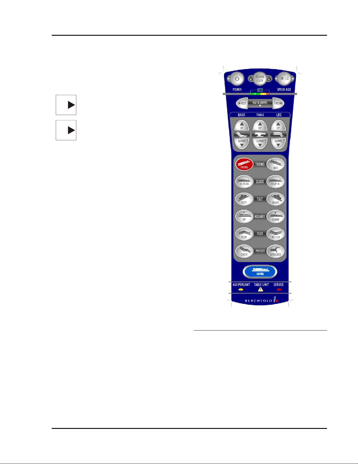
PRIMARY HAND PENDANT FUNCTIONS
1. POWER - Turns the primary hand
pendant on and off. The pendant will be
backlit when activated (unless backlight
timer is exceeded. See hand pendant
operation section)
NOTE: - The power switch on the base of
NOTE
NOTE
2. FLOOR LOCK - Raises (unlocks) or lowers
3. SPEED ADJUST (HI/LO) – changes the
4. AUTO DRIVE REV/FWD - (Optional)
5. BACK v - Raises and lowers the back
6. TABLE v - Raises and lowers the entire
7. LEG v - Raises and lowers the leg section.
8. TREND/REV TREND
9. SLIDE FOOT/SLIDE HEAD - Slides the
10. TILT LEFT/TILT RIGHT - Rotates the
11. UP KIDNEY/DOWN KIDNEY - Raises
12. FLEX - Combines back down with reverse
13. REFLEX - Combines back up with
14. CHAIR - Combines back up, Trendelenburg,
the table must be in the ON position before
the hand pendant will operate.
NOTE - If AC power is not present, the
auto-shutdown feature will turn the control
pendant off after a preset period of nonuse. To reactivate the pendant, press any
function button. If AC is present, the autoshutdown feature is disabled, and the hand
pendant remains on until it is turned off.
(locks) the floor feet.
rate of speed of all movements between
normal and slow. This is useful when
gradual motion is required.
drives the table toward the head (forward) or
foot (reverse). There is a slow acceleration,
followed by a higher speed (~0.75m/s) if
held.
section.
tabletop.
(Trendelenburg) - Tilts
the entire tabletop about the transverse axis.
table top toward and away from the head.
entire tabletop about the head to foot axis
.
and lowers the kidney elevator.
Trendelenburg to form an inverted V
(jackknife position).
Trendelenburg to return from FLEX position.
and leg down functions to form a chair-like
support. The three functions operate in a
repeating sequence until the back section
reaches 90° relative to the seat section and
the leg sections reach 105° degrees relative
to the seat section.
Figure 1-4 Primary Hand Pendant
Functions
15. UROLOGY – Levels the table; then
lowers the leg section to 90° or until a
software limit is reached. (To bring the
table to its lowest position and have LEG
at 90°, slide must be fully toward the leg
end)
16. LEVEL - Moves the table to a horizontal
position that is within 1 degree of level.
This function should be used prior to the
Flex and Chair Functions.
700000120 Rev. 1
1-5

OPERON D 850 SURGICAL TABLE
GENERAL INFORMATION
TO ITS FULL OUTERMOST POSITION
FOOTSWITCH (Optional)
A footswitch control is available for procedures
where the surgeon is normally seated at the
pelvic end of the patient (Figure 1-5).
ENABLES THE AUXILIARY PENDANT
AND DISABLES THE MAIN HAND
PENDANT.
To use the manual foot pump:
Footswitch functions include:
1. Pull the foot pedal straight out as far as it
• Trendelenburg/Reverse Trendelenburg
• Tilt Left/Tilt Right
• Table Up/Down
will go. It will rotate counter clockwise
as it is pulled outward.
The footswitch is connected into the remote
control connector box by aligning the red dot on
the footswitch connector with the red dot on the
socket in the remote control connector box. See
Figure 1-5 for location of connector.
Table Up/
Table Down
Tilt Le ft/
Tilt Right
Reverse Trendelenburg
Figure 1-5 Footswitch
Pressing one of the footswitch controls turns the
table on and places it in “controls active” status.
However, none of the functions will operate
unless the floor locks are set. The floor locks
must be operated through the hand pedant.
MANUAL FOOT PUMP
The manual foot pump is used to provide
hydraulic pressure when there is no electric
power to operate the hydraulic pump. This
could occur due to any of the following
conditions:
• Battery power is low as indicated by a
steady or flashing red battery light on the
hand pendant.
• A combined failure of the battery and AC
mains power supplies.
• A failure of the table’s hydraulic pump or
the electrical system that powers the
hydraulic pump.
• A failure of table controls
The manual pump pedal is located at the patient
left side near the head end of the base.
DEPLOYING THE FOOT PUMP HANDLE
Figure 1-6 Deploying Foot Pump Pedal
2. Extend the pedal until it clicks into
position.
3. To articulate the table, press and hold the
desired function button on the auxiliary
control pendant (see next section) and
operate the manual pump with your foot.
For best results, depress the pump pedal
completely, making full strokes, at the
rate of about one stroke per second.
To re-insert the pump pedal:
1. Push the pedal back into the table until
the end is inserted into the base cover.
2. Continue to push the pedal into the table
until it snaps into the retracted position.
EMERGENCY UNLOCK
In the unlikely situation where the control
system is completely disabled AND the
auxiliary system is disabled, there is a back-up
emergency switch that will allow the table to be
unlocked and moved. It is wired directly to the
batteries. There should always be enough power
in the batteries to open the valve solenoids. This
switch is located inside the base near the foot
pump handle storage location.
Rev. 1 700000120
1-6

OPERON D 850 SURGICAL TABLE
GENERAL INFORMATION
Figure 1-7 Emergency Switch
Do this to access this switch:
1. Pull the foot pedal straight out as far as it
will go. It will rotate counter clockwise as it
is pulled outward.
2. Put one finger through the handle storage
hole as shown and press the button.
3. The floor locks should release and the table
should be resting on its casters.
4. Press the button again to switch off the
power to the valve solenoid.
AUXILIARY HAND PENDANT
NOTE — Activating the auxiliary
NOTE
hand pendant disables the primary
hand pendant.
.The auxiliary hand pendant is identical to the
main hand pendant. It has limited function when
plugged into the auxiliary control connector,
located in the auxiliary hand pendant
compartment on the head end of the column.
The active functions are Leg Up/Down, Table
Up/Down, Back Up/Down, Floor Lock, Trend,
Tilt Left/Right, and Kidney Up/Down. Only
these buttons will be backlit when in auxiliary
mode.
Figure 1-8 Auxiliary Hand Pendant
NOTE — The Auxiliary hand
NOTE
pendant is identical to the main hand
pendant and may be used as a
replacement for the main hand
pendant. See Primary Hand Pendant
for details.
Use the auxiliary control pendant when:
• The primary hand pendant will not
function.
WARNING — The auxiliary hand
WARNING
CAUTION
pendant functions will operate
regardless of whether the floor feet
are locked or unlocked. If the floor
feet are unlocked, the table may roll
when the manual pump is operated.
CAUTION — The auxiliary hand
pendant does not have the following
functions: AUTO DRIVE, HI/LO,
FLEX, REFLEX, UROLOGY,
CHAIR, RETURN TO LEVEL, and
SLIDE. This pendant is intended to
be used for completing procedures,
followed by charging the batteries or
servicing the table.
700000120 Rev. 1
1-7

OPERON D 850 SURGICAL TABLE
GENERAL INFORMATION
Rev. 1 700000120
1-8

OPERON D 850 SURGICAL TABLE
GENERAL INFORMATION
700000120 Rev. 1
1-9

OPERON D 850 SURGICAL TABLE
GENERAL INFORMATION
TABLE 1-1 TECHNICAL DATA
Electrical Power
Requirements:
115 V AC +/-10%
50/60 Hz, 6A, Single-phase.
Environmental and Storage Requirements:
Operation
Ambient temperature range of 50 to 100° F (10 to 38° C), relative
humidity range of 10% to 95%, at altitudes from sea level to 8000 ft.
Transport and Storage
Ambient temperature range of –30 to +150° F (-34 to 66° C) relative
humidity range of 0% to 95% at altitudes from sea level to 50,000 ft.
Table Top Radiolucent and conductive carbon fiber panels conform to 21 CFR
Subchapter J, Radiation Control for Health and Safety Act of 1968.
Dimensions:
Length 82.6 inches (1930 mm)
Width 21 inches (533 mm); excluding the side rails.
Weight Approximately 750 lbs. (340 kg)
Height Range 22.6” to 46.4” (573 mm to 1179 mm)
Head Section 12.2” (310 mm) X 21” (533 mm)
Back Section 22.6” (574 mm) X 21” (533 mm)
Seat Section (w/kidney
23.1” (587 mm) X 21” (533 mm)
elevator)
Kidney Elevator 4.3” (109 mm) X 21” (533 mm)
Leg Section 24.6” (625 mm) X 21”(533 mm)
Range of Motion:
Trendelenburg
Reverse Trendelenburg
Lateral Tilt
Back Section
Up to 30°
Up to 31°
Up to 20° right or left
From 45° below horizontal to 90° above horizontal
Kidney Elevator Extendable up to 3.7” (76 mm)
Leg Section
Headrest
From 30° above horizontal to 105° below horizontal
Adjustable from 90° below horizontal to 90° above horizontal in 15°
increments
Longitudinal Slide 16.8” (427mm) total
Flex
Chair
226°
Leg Section up to 105°, Back Section up to 90° relative to the Seat
Section, which may be up to 30° in the Trendelenburg position.
Load Capacity:
Lifting and Articulation 1000 lbs. (453 kg) all articulations (500 lbs. if patient is reversed)
If you need assistance, call Berchtold Technical Service at 800-243-5135.
.
Rev. 1 700000120
1-10

OPERON D 850 SURGICAL TABLE
OPERATING INSTRUCTIONS
OPERATING INSTRUCTIONS
PINCH POINTS
WARNING — Cutting or crushing
WARNING
CAUTION
injury may occur if any part of a
patient or staff member is caught in a
pinch point when the table is
articulated.
CAUTION — Damage to the table or
object may occur if any foreign object
is caught in a table pinch point when
the table is articulated.
Due to the variety of table positions attainable
with the OPERON D 850 table, pinch or
crushing points exist (Figure 2-1). The OR staff
must be trained to ensure that body parts or
surgical apparatus are not caught in pinch points
when the table is operated.
This list is not all-inclusive, because pinch
points can be created by the attachment of
accessories. Always ensure that the patient and
staff are clear of all pinch points before moving
the table or while the table is in motion.
Pinch points include but are not limited to:
1. Kidney elevator to seat top
2. Kidney elevator to seat channels
3. Kidney elevator to back section
4. Headrest to back section
5. Back / Leg section link to seat channel
6. Side shields to column shields (in tilt)
7. Column shields to base cover
8. Base to floor
9. Floor feet to base
10. Floor feet to floor
11. Leg section to column shield
12. Foot pump handle to floor
13. Back Section to seat top.
13
5
11
12
1 2 3
4
5
6
7
10
8
9
Figure 2-1 Pinch Points
Rev. 1 700000120
2-1

OPERON D 850 SURGICAL TABLE
OPERATING INSTRUCTIONS
ELECTROMAGNETIC INTERFERENCE
WARNING — When using the table in
WARNING
the vicinity of high-frequency surgical
equipment, such as cardiac
defibrillators and cardiac defibrillator
monitors, refer to the equipment
manufacturers’ instructions to ensure
compatibility issues are considered.
This surgical table has been tested to EN 606011-2 to ensure proper electromagnetic
compatibility. Other products used in the
vicinity of the surgical table should also comply
with this standard. If they do not comply,
interference between products resulting in
unintended responses may occur. Please contact
the appropriate manufacturer(s) if any problems
arise.
If the integrity of the external protective earth
conductor arrangement is in doubt, the surgical
table should be operated from its internal
electrical power source (batteries) until the
situation is corrected. The batteries require
charging at least once a week. If the integrity of
the external protective earth conductor
arrangement is in doubt, and the batteries are not
charged, operate the surgical table with the
manual foot pump and the auxiliary hand
pendant until the situation is corrected.
LOAD CAPACITY
WARNING — Overloading may result
WARNING
in tipping of the table or failure of the
table sections to move. Do not exceed
the maximum load.
• Left and right, refer to the patients left
and right.
Figure 2-2 Table Orientation
PATIENT POSITIONING
WARNING — POSSIBILITY OF
WARNING
TIPPING: If FULL SLIDE FORWARD
IS REQUIRED, the patient’s pelvis
must always be located over the seat
section. Utilizing full forward slide
while the patient’s pelvis is closer to
the back section can impair table
stability and result in patient injury or
equipment damage.
When the patient is placed in the Lithotomy
position on the seat section, the following
precautions must be followed to ensure safety
and stability:
• The table must be securely locked to the
floor and not mobilized while the patient is
in this position.
WARNING — The leg section may be
WARNING
removed from the table. If it is left on
the table, use caution when raising the
leg section while the patient is in the
normal perineal position.
The patient lifting and articulation capacity
is 1000 lbs (453 kg). This means that a
1000 lb patient can be moved into any of the
standard procedural positions.
WARNING— Weight Limit in
WARNING
reverse, while not recommended, it
is possible to place a patient in
reverse orientation. Patient weight
must not exceed 500 lbs. when
placed in reverse.
PATIENT ORIENTATION
Orientation is defined as follows:
• The head end is the end where the power
cord is connected.
• The Perineal cutout in the seat section is
exposed
Rev. 1 700000120
2-2
Figure 2-3 Normal Perineal Position
Certain ENT, Neuro, and Ortho procedures
require that the table be moved after

OPERON D 850 SURGICAL TABLE
OPERATING INSTRUCTIONS
anesthetizing the patient. If this is required,
the following steps must be followed:
• Be sure that the patient is properly
secured to the table with straps.
• Center (slide) the patient over the main
lift column.
• Lower the table to its lowest point.
• Check the floor for and remove objects
that may interfere with moving the table,
such as power cords or table accessories.
• Have at least one person at each end of
the table.
• Unlock the table.
• When moving the table, the people at
each end must use a lateral force in the
direction of motion; do not lift up on a
section or push down on a section.
• Immediately lock the table when the new
location is reached.
OPERATION
CAUTION — Storage of clamps,
CAUTION
NOTE
If desired, plug the table’s power cord into a
mains power source. When the table is plugged
in via the power cord, it is powered by mains
AC. When the power cord is not plugged in, the
batteries provide power to the table. In either
case, the ON/OFF switch on the base must be
ON to articulate any table sections. When the
ON/OFF switch on the base is OFF, the table’s
electronics and pump motor are isolated from
the power supply and the batteries.
When the charge indicator lamp near the power
cord receptacle is lit, the table senses mains AC
and activates the battery charging system.
Battery charging will occur whether the
ON/OFF switch on the base is in the ON or OFF
position. The table can remain plugged into AC
indefinitely without damaging the batteries.
accessories, etc., on the base cover
may result in damage to lift column
shields and prevent proper elevation
or descent of the table.
Note — The table can be operated
with or without the power cord
connected to the mains inlet
receptacle. Plug in the power cord if
the batteries need recharging. The
table may be operated while the
batteries are charging.
HAND PENDANT OPERATION
The table may be activated by pressing the hand
pendant ON button or by pressing any of the
hand pendant function buttons.
If you activate the table by pressing the ON
button, the hand pendant LEDs for all Battery
levels will flash briefly. This is a self-test
function. During this time, no function is active.
If there is a problem with the hand pendant, the
connection to the table, or any of the table
functions, the SERVICE LED will remain on.
If there are no problems, all LEDs except the
Power, current floor lock status, and battery
status displays will turn off, and the function
buttons will become back lit to indicate that the
table is in a “controls active” status.
To conserve battery power, the hand pendant
will automatically go into SLEEP MODE after a
preset period of non-use (default value). This
time can be changed through the table’s Service
Software Program, which is described in the
“Service Program” section of this manual.
Additionally, hand pendant backlighting will
turn off after a preset period of non-use (default
value). This time can also be changed through
the table’s Service Software Program.
If you activate the hand pendant from the
SLEEP MODE by pressing any of the function
buttons (other than the ON button), the self-test
will be performed after the button is released. If
the floor locks are NOT locked, the back
lighting will come on, and the hand pendant will
go into “controls active” status, the feet will
automatically descend and lock.
1. Press the ON button on the control
pendant to activate the control pendant
2. Press FLOOR LOCK to lower the floor
feet. The green LOCK indicator on the
control pendant will light when the floor
feet are locked.
3. Select the desired function by pressing
and holding the appropriate function
switch.
4. When the desired position has been
reached, release the function button to
stop movement.
5. After the patient has been transferred
from the table, press FLOOR LOCK to
raise the floor lock feet and allow table
transport. The yellow UNLOCK
700000120 Rev. 1
2-3
 Loading...