

Berchtold Elektrotom 630 Service manual
ELEKTROTOM® 630
Service Manual (E)
Valid for version 1170, 1171

ELEKTROTOM® 630 valid for version 1170, 1171 Service Manual (E)
CONTENSPAGE
1.General4 - 6
1.1Introduction4
1.2Manufacturer’s notes4
1.3General information4 - 5
1.4Notes on product responsibility5
1.5Routine checks following delivery5
1.6EC certification5
1.7Repairs5 - 6
1.7.1Replacement of fuses5 - 6
1.8Technical safety controls6
1.9Type plate identification7
2.Commissioning7 - 9
2.1Installation7
2.2Important notes for fafe usage7 - 8
2.3First usage8
2.4Visual and functional checks before each use8
2.5Cleaning, disinfecting and sterilisation8 - 9
2.5.1Cleaning and disinfection of the unit8
2.5.2Cleaning, disinfection and sterilisation of accessories8 - 9
3.Operating the ELEKTROTOM® 63010 - 15
3.1Puhsbuttons, signal lights and symbols10 - 15
3.1.1The front of the ELEKTROTOM® 630 version 117010
3.1.2The front of the ELEKTROTOM® 630 version 117111
3.1.3The rear of theELEKTROTOM® 63012
3.1.4Description of the puhsbuttons and symbols12 - 15
3.1.5Symbol markings on the rear of the unit15
4.Technical description15 - 17
4.1Technical data15 - 16
4.1.1Mains connection15
4.1.2HF current output and current characteristics15 - 16
4.2Safety relevant data17
4.3Equipment for user support17
4.4Dimensions and weight17
4.5Certification17
5.Power output diagram18 - 24
5.1Power output in relation to resistance (output characteristic)18 - 21
5.1.1Current type CUT I18
5.1.2Current type CUT II18
5.1.3Current type CUT III19
5.1.4Current type CONTACT COAGULATION19
5.1.5Current type FORCED COAGULATION20
5.1.6Current type SPRAY COAGULATION20
5.1.7Current type BIPOLAR COAGULATION21
2

ELEKTROTOM® 630 valid for version 1170, 1171 Service Manual (E)
CONTENSPAGE
5.2Peak voltage in relation to power regulator21 - 24
5.2.1Current type CUT I21
5.2.2Current type CUT II22
5.2.3Current type CUT III22
5.2.4Current type CONTACT COAGULATION23
5.2.5Current type FORCED COAGULATION23
5.2.6Current type SPRAY COAGULATION24
5.2.7Current type BIPOLAR COAGULATION24
6.Positiones of spare parts25 - 26
6.1Valid for version 117025
6.2Valid for version 117126
7.Spare part list27
8.Adjustment neutral electrode control27
9.Trouble shooting and repair28
10.Check of the HF power28
11.Function and connection diagram29
12.Power board30
13.Front board31
14.Tonegenerator board32
3

ELEKTROTOM® 630 valid for version 1170, 1171 Service Manual (E)
1.GENERAL
1.1 Introduction
Electrosurgery belongs to the most important energy applications in surgery. In all surgical disciplines, it remains
the most effective means of combining tissue cutting and haemostasis. The electrosurgical unit, the ELEKTROTOM® 630 electrosurgical unit is a modern instrument combining economy with a considerable degree of
operative flexibility. The unit has a capable output of 300 Watts.
Particularly important features of the ELEKTROTOM® 630 include:
•Enhanced user simplicity and safety via integrated microprocessor technology
•Three current types offering excellent cutting qualities combined with simultaneous haemostasis
•Bipolar coagulation with up to 95 Watts output
•Contact coagulation up to 120 watts, effective forced coagulation (standard) up to 150 watts, and spray coagulation up to 100 watts.
•User friendly control panel with foil covered pressure pads and digital read-out display
•The highest degree of safety using modern, negative electrode monitoring technology, for both single and split
negative electrodes
•A malfunction, error code display system, showing user information and offering assistance during service and
repair procedures
All the advantages of the ELEKTROTOM® 630 can be put to optimum use by the user if these instructions are
observed. These will assist you in competent operation, correct selection and handling of your HF instruments.
1.2 Manufacturer´s notes
The manufacturer of the products specified in the service manual is
BERCHTOLD Holding GmbH
Ludwigstaler Straße 25
Postfach 4052
D-78505 Tuttlingen
Internet: http://www.BERCHTOLD.de
e-mail: BERCHTOLD.Medizinelektronik@BERCHTOLD.de
Tel. (+49) 7461 / 181-0
Fax (+49) 7461 / 181-200
1.3 General information
•Precise observance of the user’s manual is a prerequisite for the proper use and correct operation of the equipment, which is essential for the safety of patients and operators alike.
•Only accessories which are specified in this user’s manual and which have been tested together with the equipment may be used. If accessories are used which are not specified in the user’s manual, their ability to be used in
accordance with safety regulations must be proved.
4

ELEKTROTOM® 630 valid for version 1170, 1171 Service Manual (E)
•All literature relates to the equipment model and the prevailing basic safety regulations when printed. All rights
are reserved for equipment, switches, procedures, software programs and names.
1.4 Notes on product responsibility
The BERCHTOLD company can only consider themselves responsible for the safety, reliability and function of
the product under the following conditons:
a)installation, modifications or repairs have been performed only by BERCHTOLD or by an agent expressly
authorized by BERCHTOLD to do so,
b)the electrical installation of the room complies with regulations IEC 60364-710,
c)the product is used in accordance with the operating instructions.
1.5 Routine checks following delivery
The product and accessories should be inspected for possible transport damage or other defects immediately on
arrival.
Reclamation regarding damage or defects can only be entertained by the selling organisation (BERCHTOLD
GmbH & Co.) or the delivering agency when they are immediately reported. In case of complaint, the forwarding
agent or the BERCHTOLD sub-agency must immediately be informed, prior to the submission of a damage /
deficiency report to the BERCHTOLD main offices in Germany for further processing by our insurance agents.
When returning a unit or one of its components to BERCHTOLD or to a BERCHTOLD service centre, every
effort should be made to use the original packaging material. The following information/documentation must also
accompany the returned items:Name and address of the owners, product identification number (see plate affixed
to unit), Detailed description of the defect.
1.6 EC certification
The equipment complies with the requirements of the EC guideline regarding medical products, 93/42/EEC.
1.7 Repairs
By obvious defect, either of the unit or its connecting cable, it must be repaired or its cable renewed before being
used again.
The ELEKTROTOM® 630 may only be repaired by BERCHTOLD or their officially appointed agent.
Should the unit be repaired by an officially appointed agent, the user is required to obtain written confirmation of
the work carried out.
This signed confirmation should bare the date of the repair and the details of the officially appointed agent. When
repairs are not carried out by BERCHTOLD direct, the repairing organisation must append their details to the
unit or, that part of the unit which has been repaired.
1.7.1 Replacement of fuses
The mains fuses is to be found the fuse housing (35) below the mains cable socket (36) at the rear of the unit.
5

ELEKTROTOM® 630 valid for version 1170, 1171 Service Manual (E)
Changing the fuse is performed as follows:
•Remove the mains cable from its socket (36),
•Using a small screw driver, prise open the flap covering the fuse housing (35) and fold it upwards,
•Remove the red fuse holder and replace the defective fuse. Take care to use a fuse of the correct value which is
written on the fuse holder. T 6,0 A,
•Re-insert the red fuse holder and close the flap before re-inserting the mains cable in the socket (36).
1.8 Technical safety controls
The following controls must be carried out at least on a yearly basis:
•Visual checking for any mechanical or functional defect
•Safety relevant markings on the unit must be readable
•Checking of the mains fuses against nominal electrical value
•Checking the calibration of the HF current output against the setting of the UP/DOWN button of the control
panel
•The actual output measurement for the current modes and the coagulatory modes should be checked to the
values the laid down in the specifications for the unit.
•Checking of optical and acoustic signalisation
•Compare protected resistance according to EN 60601-1
with mains connection:
Limit 0.2 Ω
•Measure case leakage according to EN 60601-1Limit 0.50 mA (N.C.) *
Limit 1.00 mA (S.F.C.) **
•Gehäuseableitstrom lt. EN 60601-1 messen:Limit 0.10 mA (N.C.) *
Limit 0.50 mA (S.F.C.) **
•Measure patient leakage according to EN 60601-1Limit 0.01 mA (N.C.) *
Limit 0.05 mA (S.F.C.) **
•Measure patient leakage according to EN 60601-1
Limit 0.05 mA (S.F.C.) **
(Mains voltage at used instrument)
* N.C. = Normal condition
** S.F.C. = Single fault condition
The results of the technical safety checks should be documented.
Should the unit prove to be defective or otherwise unsafe it must not be used until repaired.
6
ELEKTROTOM® 630 valid for version 1170, 1171 Service Manual (E)
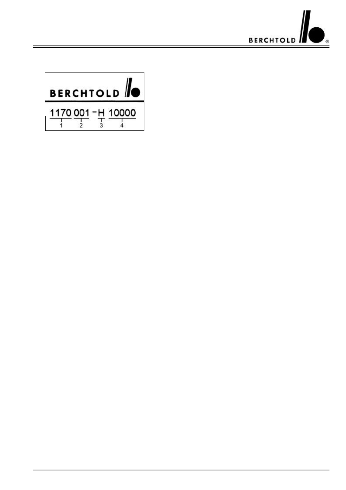
1.9 Type plate identification
1Version number
2Variant
3Manufacturing year
4Serial number
2.COMMISSIONING
2.1 Installation
The unit is intended for use only in a medical environment and connection to the mains must be in accordance
with the IEC 60364-710 regulations. Further, connection to the mains should be via a suitably protected socket
using the mains lead and plug provided by the manufacturer or one of an equivalent quality. For safety reasons,
extension leads or multi-socket connections should not be used. The mains socket must be protected by a fuse
rated at not less than 10 Amperes.
The ELEKTROTOM® 630 can be placed on any flat surface with a tilt angle not in excess of 10°. The surface
itself should be equivalent in size to that of the unit. Care must be taken not to block the air vents on the underside of the generator and ensure a free flow of air around the unit. The ELEKTROTOM® 630 should be protected from the danger of fluids entering the unit.
For intracardiac surgery this equipment must be connected to the main power stabilizer in the operating room or
location where it is installed by means of the (yellow/green) power-stabilization cable supplied.
2.2 Important notes for safe usage
Misuse of the generator and a disregard of these instruction can lead to serious injury!
Take care to study these instructions supplied with your ELEKTROTOM® 630.
Warning!
The unit is not intended for use in explosion endangered areas.
Caution must be exercised when anaesthetic gas mixtures such as Oxygen (O2) and nitrous Oxide (N2O) are used
during surgery in the thoracic or head regions. The use of anaesthetic gas, exhaust management systems is to be
recommended. Inflammable substances used for cleaning or disinfection or, particularly, solvents used to remove
adhesives, must be removed or fully evaporated before the using an electrosurgical unit. The danger of pocketing
or pooling of inflammable liquids or vapours in body cavities such as the navel or vagina as well as in the depths
of surgical wounds which must also be considered and not underestimated. Liquids must not be allowed to gather
or pool under the patient. The presence of endogenic gases which may be ignited, must also be taken into account
when using electrosurgical equipment on the gut and a system of inert gas flushing is recommended. Material
such as cotton wool or gauze can, in certain circumstances, also be ignited via HF current induced sparking - particularly in the presence of oxygen.
The use of electrosurgery requires caution and the following rules should be considered:
•The high frequency current output of the unit should be minimal and not more than is required for the task to
be performed.
7

ELEKTROTOM® 630 valid for version 1170, 1171 Service Manual (E)
Note:
A reduced or lack of function after setting the unit output controls at 'normal' power can be caused by a number of factors such as
neutral electrode problems, bad connections, damaged cables or a crusted active electrode. Theses point should be considered before
selecting what might be a much higher unit output than necessary.
•Do not attempt to test the unit by directly discharging against a metal object or the negative electrode.
•The function of other electromedical equipment can be interfered with by the use of high frequency current.
•The switching mechanisms of an electrode handle which is not completely water tight, may be penetrated by
blood, saline or other rinsing liquids or amniotic fluid producing an unpredictable response from the generator.
•In order to prevent accidental HF current burns, the electrode handle should be placed on the instrument trolley
when not in use and not on the patient.
•Placing a finger switched, electrode handle onto very damp drapes or, into pooled liquid on the drapes, may
cause patient burns directly below the electrode handle.
2.3 First usage
Before the unit is first used surgically, the Manufacturer or their official agent shall:
b)have fully tested the unit in the position in which it is to be used;
c)have given full operational instructions for the unit to a responsible person.
2.4 Visual and functional checks before each use
Before each use the user must be sure that the unit and its accessories are in good working order.
The following visual checks should be made:
•check for external damage to the unit, insulation and plugs,
•check that the appropriate accessories a present and that they fit,
•Very carefully check the insulation on endoscopic instruments.
Damaged or doubtful equipment must not be used.
Warning!
Should the flow of HF current be indicated by the unit without the attachment of a foot-switch or electrode handle with a double, finger
switch then the unit is faulty and must be examined before use. An indicated malfunction following the attachment of a foot-switch or
electrode handle with double, finger switch shows a defective accessory which must be checked and eventually replaced.
2.5 Cleaning, disinfecting and sterilisation
2.5.1 Cleaning and disinfecting of the ELEKTROTOM® 630
The entire exterior of the unit, including the foil covered operating panel, can be cleaned with normal, alcohol free
cleaning fluids. (Spray or wipe disinfecting)
Please take note of the manufacturers instructions for disinfectant solutions.
8

ELEKTROTOM® 630 valid for version 1170, 1171 Service Manual (E)
2.5.2 Cleaning, disinfecting and sterilisation of accessories
After use, accessories may be soaked in standard disinfecting solutions following the instructions of the manufacturers, without exceeding soaking times. The life expectancy of some plastics may be shortened by certain
chemicals and a thorough rinsing of all accessories is important. Phenol and chlorine solutions are not suitable.
Alternatively, a mechanised washing and thermal disinfecting process is acceptable, provided temperatures do
not exceed 93° C/10 min..
Good operative results can only be expected when the active and negative electrode are perfectly clean and free
from any dried protein.
Connecting cables and the insulation of active electrodes must be constantly checked and maintained in perfect
condition. Articles with damaged insulation must not be used.
The following sterilisation temperatures are acceptable:
Gas sterilisation
up to 70 °C
Connecting cables for
electrode handleyesyesno
Electrode handleyesyesno
Active electrodesyesyesyes
Bipolar coagulation
forcepsyesyesno
Steam sterilisation
up to 134 ° C
Hot air sterilisation
at 200 ° C
9
ELEKTROTOM® 630 valid for version 1170, 1171 Service Manual (E)
3.OPERATING THE ELEKTROTOM® 630
3.1 Puhsbuttons, signal lights and symbols
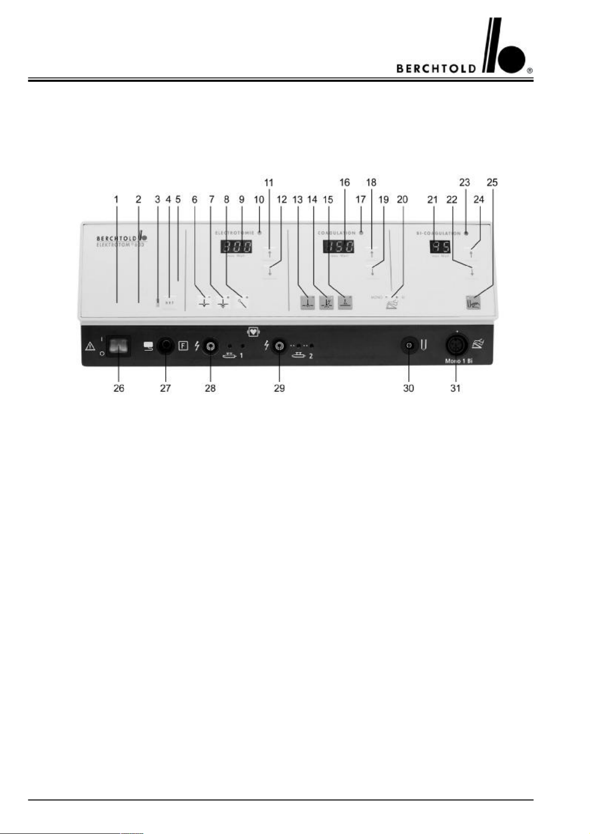
3.1.1 The front of the ELEKTROTOM® 630 version 1170
1Symbol indicating „split, neutral electrode applied“
2Symbol indicating „single, neutral electrode applied“
3Signal light red for negative electrode alarm
4Button to confirm the correct application of a negative electrode (SET button)
5Service indication: when this lights up, a service technician should inspect the unit within one week
6Button for Cut I “cutting with minimal tissue charring”
7Button for Cut II “cutting with medium tissue charring, also for “transurethral resection”
8Button for Cut III “cutting with wire loop electrodes for polypectomy and papillotomy”
9Digital output indicator in watts for cutting power
10Signal light indicating activation - cutting current
11Button to increase cutting output
12Button to decrease cutting output
13Button for contact coagulation
14Button for forced coagulation
15Button for spray coagulation (ray of sparks coagulation)
16Digital output indicator in watts for coagulatory power
17Signal light indicating activation - coagulatory current
18Button to increase coagulating output
19Button to decrease coagulating output
20Button for double foot-switch use in either monopolar or bipolar coagulation
21Digital output indicator in watts for bipolar coagulatory power
22Button to decrease bipolar coagulating output
23Signal light indicating activation - bipolar coagulatory current
24Button to increase bipolar coagulating output
25Button for bipolar coagulating via forceps activation (auto-start mode)
26Mains, on/off switch
27Connecting socket for neutral electrode (split or single)
28Connecting socket for electrode handle, HF output 1 (with additional socket for disposable handles)
29Connecting socket for electrode handle, HF output 2 (with additional socket for disposable handles)
30Connecting socket for bipolare coagulations instruments
31Connecting socket for foot-switch (for HF output 1 and bipolar coagulation)
10
ELEKTROTOM® 630 valid for version 1170, 1171 Service Manual (E)
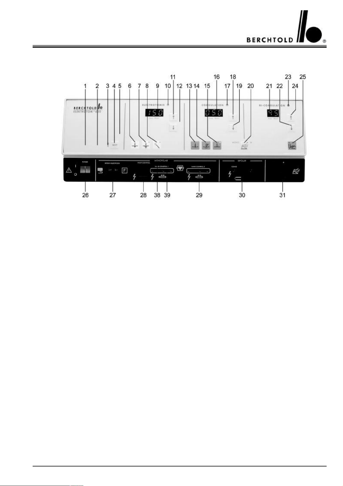
3.1.2 The front of the ELEKTROTOM® 630 version 1171
1Symbol indicating „split, neutral electrode applied“
2Symbol indicating „single, neutral electrode applied“
3Signal light red for negative electrode alarm
4Button to confirm the correct application of a negative electrode (SET button)
5Service indication: when this lights up, a service technician should inspect the unit within one week
6Button for Cut I “cutting with minimal tissue charring”
7Button for Cut II “cutting with medium tissue charring, also for “transurethral resection”
8Button for Cut III “cutting with wire loop electrodes for polypectomy and papillotomy”
9Digital output indicator in watts for cutting power
10Signal light indicating activation - cutting current
11Button to increase cutting output
12Button to decrease cutting output
13Button for contact coagulation
14Button for forced coagulation
15Button for spray coagulation (ray of sparks coagulation)
16Digital output indicator in watts for coagulatory power
17Signal light indicating activation - coagulatory current
18Button to increase coagulating output
19Button to decrease coagulating output
20Button for double foot-switch use in either monopolar or bipolar coagulation
21Digital output indicator in watts for bipolar coagulatory power
22Button to decrease bipolar coagulating output
23Signal light indicating activation - bipolar coagulatory current
24Button to increase bipolar coagulating output
25Button for bipolar coagulating via forceps activation (auto-start mode)
26Mains, on/off switch
27Connecting socket for neutral electrode (split or single)
28Connecting socket for electrode handle, HF output 1, activation with foot-switch
29Connecting socket for electrode handle with 3-pin plug, HF output 2
30Connecting socket for bipolare coagulations instruments
31Connecting socket for foot-switch (for HF output 1 and bipolar coagulation)
38Slide for release of socket 28 or socket 39
39Connecting socket for electrode handle with 3-pin plug, HF output 1
11
 Loading...