

Berchtold Elektrotom 610 Service manual
ELEKTROTOM® 610
Service Manual
Valid from version 1132

2
ELEKTROTOM® 610 Service Manual
Contents
Page
1. Introduction
5
2. Routine checks following delivery
5
3. Initial installation
5
4. First usage
6
5. Important notes for safe usage
6
6. Surgical indications
6
7. Principles of electrosurgery and techniques
6
8. Function of the ELEKTROTOM® 610
6
- 13
8.1
Current types for 2 cutting modes with differing effects
6
- 7
8.2
Current types for 2 monopolar coagulation modes with differing effects
8
- 10
8.2.1
Forced Coagulation
8 8.2.2
Soft Coagulation
8
- 10
8.3
Bipolar Coagulation
10
- 11
8.4
Safety relevant function
11
- 13
8.4.1
Computer supported safety features
11 8.4.2
Neutral electrode monitoring
11
- 13
8.4.3
Protection against unit malfunction
13
8.4.4
Protection against erroneous unit settings
13
9. Operating of the ELEKTROTOM® 610
14
- 18 9.1
Push buttons and signal lights
14
- 18
9.1.1
The front of the ELEKTROTOM® 610
14 9.1.2
The rear of the ELEKTROTOM® 610
15
9.1.3
Description of the push buttons and symbols
16
- 18
10. Commissioning
18
- 19 10.1
HF currents interference
18
- 19
10.2
Using multiple functions
19
11. Visual and functional checks before each use
19
12. Cleaning, disinfection and sterilisation
20
12.1
Cleaning and disinfection of the unit
20 12.2
Cleaning, disinefection and sterilisation of accessories
20
13. Repairs
20
- 21
13.1
Replace of fuses
21
14. Technical safety controls
21
- 22
15. Guarantee
22

3
ELEKTROTOM® 610 Service Manual
Contents
Page
16. Technical description
22
- 24 16.1
Technical Data
22
- 23
16.1.1
Mains connection
22
16.1.2
HF current output and current characteristics
22
- 23
16.2
Safety relevant data
24 16.3
Provision for man / machine communication
24 16.4
Dimensions and weight
24 16.5
Certification
24
17. Power output diagram
25
- 29 17.1
Power output in relation to resistance (output characteristic)
25
- 27
17.1.1
Current type CUT I
25 17.1.2
Current type CUT II
25 17.1.3
Currents type FORCED COAGULATION
26 17.1.4
Currents type SOFT COAGULATION
26 17.1.5
Current type BIPOLAR COAGULATION
27 17.2
Peak voltage in relation to power regulator
27
- 29
17.2.1
Current type CUT I
27
17.2.2
Current type CUT II
28 17.2.3
Currents type FORCED COAGULATION
28 17.2.4
Currents type SOFT COAGULATION
29 17.2.5
Current type BIPOLAR COAGULATION
29
18. Function and connection diagram
30
- 31
18.1
Block diagram
30
18.2
Circuit diagram
30 18.3
Connection figure
31
19. CPU board
32
- 33 19.1
Circuit diagram
32 19.2
Block diagram
32
19.3
Layout CPU board
33
20. Switch mode power supply (SMPS)
34
- 36 20.1
Block diagram SMPS
34 20.2
Block diagram control board
34 20.3
Layout SMPS
35 20.4
Layout control board
36
21. Key board and LED controller
37
- 38 21.1
Block diagram
37 21.2
Circuit diagram front panel
37 21.3
Layout, components side
38 21.4
Layout,. soldered side
38

4
ELEKTROTOM® 610 Service Manual
Contents
Page
22. Low voltage power supply
39
22.1
Block diagram
39 22.2
Layout
39
23. Self test
40
23.1
Power on test
40
23.2
Stand-by test
40
23.3
Online test
40
24. Trouble shooting and corrective actions
40
- 43 24.1
Error list
40
- 43
24.2
Circuit compensation
43
25. Service adjustments
43
- 44
25.1
Changing the mains voltage
43
- 44
25.1.1
Switch to 110 V
43 25.1.2
Switch to 220 V
44 25.2
Switch mode power supply and power generator
44 25.2.1
Handle and footswitch module
44 25.2.2
NE module
44
26. Switch mode power supply (SPMS) sensor
45
- 46 26.1
Short circuit
45 26.2
SMPS voltage sensor
46
27. Switch mode power supply and power generator
46
- 47
27.1
Adjusting the Impedance sensor
46
27.2
Adjustments in the NE module
46 27.3
Changing the mains voltage 110/220 V
46 27.4
Handle and footswitch adjustments
46 27.5
Adjustments on the switch mode power supply and the power generator
47
28. Switch mode power supply controller
48
- 49
28.1
Checking the switch mode power supply without CPU control
48
28.2
Enabling CPU control – PWM 1kHz signal
48 28.3
Adjusting the “Short circuit” current sensor
48 28.4
Adjusting the SMPS controller
49

5
ELEKTROTOM® 610 Service Manual
1.
Introduction
Electrosurgery belongs to the most important energy applications in surgery. In all surgical disciplines, it remains
the most effective means of combining tissue cutting and haemostasis. The electrosurgical unit, the
ELEKTROTOM® 610 electrosurgical unit is a modern instrument combining economy with a considerable degree of operative flexibility. The unit has the capable output of 100 Watts.
Particularly important features of the ELEKTROTOM® 610 include:
•
Enhanced user simplicity and safety via integrated microprocessor technology
•
Two current types offering excellent cutting qualities combined with simultaneous haemostasis
•
Bipolar coagulation with up to 50 Watts output
•
Effective, contact coagulation with 60 Watts output for both
•
User friendly control panel with foil covered pressure pads and digital read-out display
•
The highest degree of safety using modern, negative electrode monitoring technology, for both single and split
neutral electrodes
•
A malfunction, error code display system, showing user information and offering assistance during service and
repair procedures
These and other advantages of the ELEKTROTOM® 610 will be discovered when studying these instructions for
use and employing the correct accessories and features of the unit in the manor for which they have been developed.
2.
Routine checks following delivery
The product and accessories should be inspected for possible transport damage or other defects immediately on
arrival.
Reclamation regarding damage or defects can only be entertained by the selling organisation (BERCHTOLD
GmbH & Co.) or the delivering agency when they are immediately reported. In case of complaint, the forwarding
agent or the BERCHTOLD sub-agency must immediately be informed, prior to the submission of a damage /
deficiency report to the BERCHTOLD main offices in Germany for further processing by our insurance agents.
When returning a unit or one of its components to BERCHTOLD or to a BERCHTOLD service centre, every
effort should be made to use the original packaging material. The following information/documentation must also
accompany the returned items: Name and address of the owners, product identification number (see plate affixed
to unit), detailed description of the defect.

6
ELEKTROTOM® 610 Service Manual
3.
Initial installation
The unit is intended for use only in a medical environment and connection to the mains must be in accordance
with the IEC 364-710 regulations. Further, connection to the mains should be via a suitably protected socket using
the mains lead and plug provided by the manufacturer or one of an equivalent quality. For safety reasons, extension leads or multi-socket connections should not be used. The mains socket must be protected by a fuse rated at
not less than 10 Amperes.
The ELEKTROTOM® can be placed on any flat surface with a tilt angle not in excess of 10°. The surface itself
should be equivalent in size to that of the unit. Care must be taken not to block the air vents on the underside of
the generator and ensure a free flow of air around the unit. The ELEKTROTOM® should be protected from the
danger of fluids entering the unit.
The generator is at intracardiac interventions supplied with a cable to balance earth potential. This should be connected to the appropriate connector in the operating theatre in order to avoid 'static' shocks when handling various apparatus.
For intracardiac surgery this equipment must be connected to the main power stabiliser in the operating room or
location where it is installed by means of the (yellow/green) power-stabilisation cable supplied.
4.
First usage
Before the unit is first used surgically, the Manufacturer or their official agent shall:
a) have fully tested the unit in the position in which it is to be used;
b) have given full operational instructions for the unit to a responsible person.
5.
Important notes for safe usage
Please see Operating instructions ELEKTROTOM® 610.
6.
Surgical indication
Please see Operating instructions ELEKTROTOM® 610.
7.
Principles of electrosurgery and techniques
Please see Operating instructions ELEKTROTOM® 610.
8.
Functions of the ELEKTROTOM® 610
8.1 Current types for 2 cutting modes with differing effects
The ELEKTROTOM® 610 provides a choice of 2 cut modes (see page 20):
•
Cut I: pure cut with no coagulation (push button 5)
•
Cut II: cut plus coagulation (blend) (push button 6)

7
ELEKTROTOM® 610 Service Manual
The unit output, and subsequent cutting power, can be varied between 5 and 100 Watts, in 5 Watt increments,
using the up/down push buttons 9 and 10. Regardless of the cutting speed, electrode geometry or tissue resistance,
the actual generated power is automatically controlled to be optimal for the procedure being undertaken.
8
ELEKTROTOM® 610 Service Manual
An integrated microprocessor permanently monitors and adjusts, within milliseconds, the unit output to accommodate varying tissue resistance.
The following active electrodes of varying diameter may be used for cutting: Needle electrodes, knife electrodes,
lancet electrodes, wire sling or loop electrodes and the broader, bangle electrodes.
The appropriate active electrode form should be selected to meet the intended cutting function.
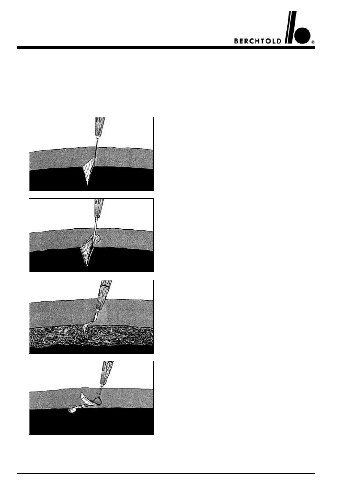
For plain cuts without coagulation (surface necrosis) needle or lancet electrodes with thin cross-section are most
suitable.
A high cutting speed reduces the likelihood of coagulating
the cut surface.
Electrodes with a large cross-section reduce the cut speed
and cause the coagulation of the cut surfaces at the same
time.
Lancet or knife electrodes are best suited when cutting
fat.
Due to the high tissue impedance of fat it is necessary to
select 1-2 steps higher than normal on the output control.
For biopsy excisions and other tissue sampling we recommend the use of loop or conisation electrodes.

9
ELEKTROTOM® 610 Service Manual
Suggested settings for cutting
Function
Suggested setting
(digital display)
Plain cuts with thin needle electrodes
40 W
Blended cuts with knife, lancet or loop electrodes
60 W
Excisions with loop electrodes
60 W
Cutting fat tissue with lancet or knife electrodes
80 W
These setting are recommended from experience. However, electrical conditions may require higher settings than
indicated.
•
8.2 Current types for 2 monopolar coagulation modes with differing effects
The ELEKTROTOM® 610 provides a choice of 2 coagulation modes (see page 20):
•
Contact coagulation (push button 12) high power coagulation (Forced coagulation)
•
Contact coagulation (push button 11) low power coagulation (Soft coagulation)
8.2.1 Forced Coagulation
Forced coagulation is a high voltage coagulation employing micro-arc technology. Further, the current is modulated to give a higher crest factor. The arcing effect is particularly suitable for large area, surface coagulation.
The required coagulation power can be regulated in 5 steps from 5 W to 60 W by means of the up/down pushbuttons 15 and 16.
Forced coagulation is normally carried out using a knife or ball shaped active electrode. The high frequency energy
is discharged directly to the surface tissues via arcing.
Suggested settings for forced coagulation
Function
Suggested setting
(digital display)
Coagulation with knife or ball electrodes
50 W
These setting are recommended from experience. However, electrical conditions may require higher settings than
indicated.
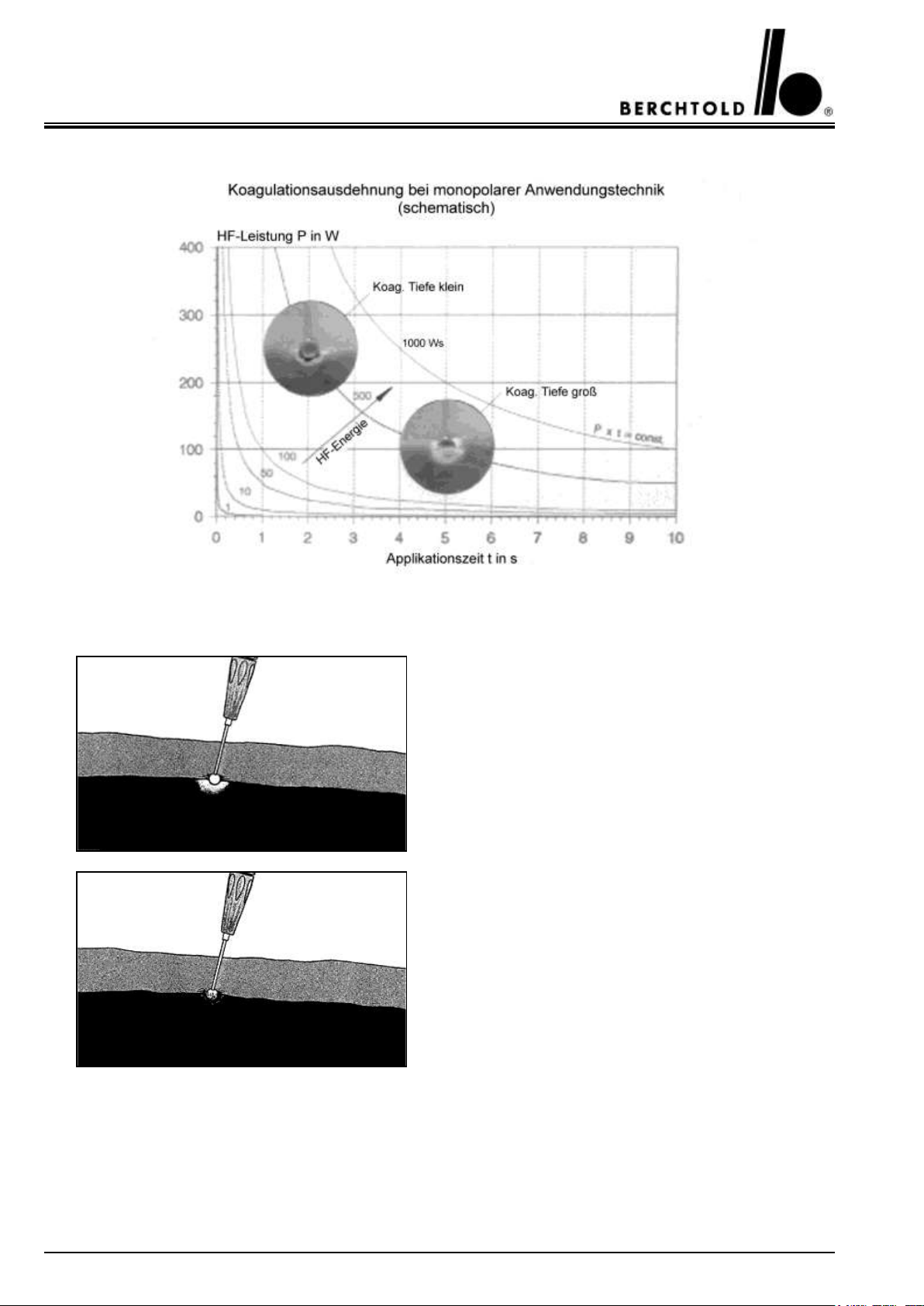
8.2.2 Soft Coagulation
Soft coagulation is a low voltage coagulation whereby the tissue are not excessively over-heated or carbonised.
Ideally, a large active electrode should be selected and the contact area with the tissue should be as great as possible. The unit output, and the subsequent coagulatory power, can be varied using in 5 steps from 5 W to 60 W by
means of the up/down push button 15 and 16. Five, unit output values may be pre-selected, in order to achieve
the required coagulatory effect. Output is selected with considering the electrode geometry (Ball electrode, plate
electrode, indirect contact with an artery forceps or tweezers type forceps) and the degree of secondary tissue heating. Lower output levels applied for longer periods of time have a greater, in depth, coagulatory effect and vice
versa.
10
ELEKTROTOM® 610 Service Manual
The special circuitry of the unit automatically controls the generator output to assure a constant coagulatory effect
while taking into account electrode geometry and changing electrical resistance in the tissues.
When high power settings are used, a rapid and narrowly
limited coagulation is achieved. In the area close to the
active electrode the tissue dries out rapidly and the current flow decreases quickly due to the increased resistance.
Please keep active electrodes clean!
Dirty electrodes have an insulating crust of tissue and
blood on their surfaces. This will hinder the flow of current.
11
ELEKTROTOM® 610 Service Manual
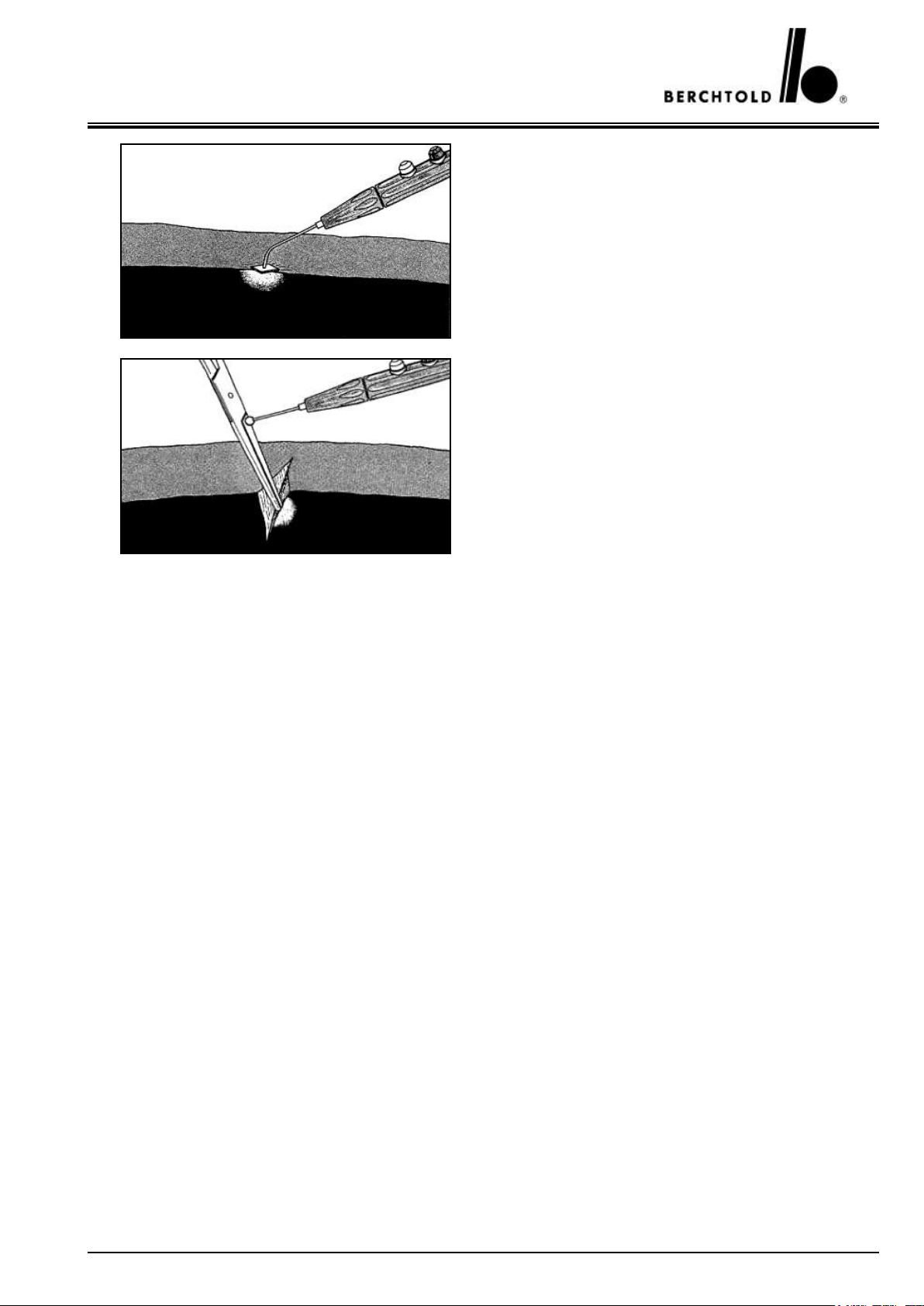
In order to staunch bleeding in weeping places and to
desiccate tissue completely in tumour surgery use ball or
plate electrodes.
Bleeding vessels can be closed rapidly and safely by means
of coagulation. The vessel needs to be taken with the
forceps or clamp. Contact of the active electrode to the
instrument conducts current from the active electrode to
the vessel.
Suggested settings for soft coagulation
Function
Suggested setting
(digital display)
Coagulation with plate or ball electrodes
50 W
Coagulation with artery clamp or forceps
50 W
These setting are recommended from experience. However, electrical conditions may require higher settings than
indicated.
8.3 Bipolar coagulation
When using a bipolar forceps or a similar instrument it is possible achieve an accurate coagulation covering a very
small area. In effect, the two tips of the forceps become ‘active’ electrodes and tissue between the tips is subject to
HF current. For example, if a vessel is held between the tips of an insulated bipolar forceps, the resistance set up
by the tissue, between the bare metal tips of the forceps, causes heat production and a subsequent coagulatory
effect.
Activation of the bipolar HF power can be effected by repeatedly pressing key 17 either as
• Automatic start (forceps start) with activation of the membrane key (17)
• Foot pedal start without activation of the automatic start or “MONOPOLAR” procedure. The double pedal foot
switch is connected to socket 25, with the blue pedal activating the bipolar coagulation.
In the case of automatic start, an impedance sensor monitors the contact of the bipolar instrument with the biotissue, so that the HF power is switched on automatically.
The electronically controlled, constant adjustment of unit output allows an automatic adaptation of power to meet
the changing electrical resistance of the tissues being treated. However, output is restricted to the pre-selected
maximum level in Watts. The constant and minimal HF current output avoids sparking and subsequent electrode
sticking.

12
ELEKTROTOM® 610 Service Manual
The constant voltage characteristic curve of the bipolar current type enables automatic power adjustment up to the
preselected maximum output in watts. The constant low HF voltage level avoids sparking and reduces adhesion of
the coagulation electrodes to the biotissue.
Notes on absence of coagulation effects
It can occur that no coagulation effect appears after HF activation. The reason for this failure is always – provided
that there is no defect in the forceps or the connection cable – contaminated forceps tips. The bipolar coagulation
generator provides a relatively low HF voltage. Dried blood or tissue residue are sufficient to insulate the forceps
tips and consequently to interrupt the current. To ensure perfect functioning, the forceps tips must be kept in a
clean, bare-metal and thus conductive condition by frequent wiping.
Suggested settings for bipolar coagulation
Function
Suggested setting
(digital display)
Coagulation with forceps
30 – 40 W
These setting are recommended from experience. However, electrical conditions may require higher settings than
indicated.
8.4 Safety relevant functions
8.4.1 Computer supported safety feature
Considerable safety features are built into the ELEKTROTOM® 610 in order to reduce the dangers of HF electrosurgery to an absolute minimum. Microprocessor control and unit output sensor technology allow the realisation of many, further control functions. Unit, ‘ready for use,’ or otherwise, is indicated both optically and acoustically while HF generation is immediately shut-down when a unit malfunction is detected.
Signals from the various sensors are monitored by the microprocessor. In the case of a microprocessor or software malfunction, HF production is immediately shut-down and an optically displayed error code is shown on the
control panel.
The ELEKTROTOM® 610 is equipped with automatic, self diagnosing circuitry and a malfunction / error code
display feature. A selection of user useful malfunction / error codes is given in the following table.
8.4.2 Neutral electrode monitoring
In the monopolar mode, the negative electrode (patient end-plate) plays a particularly important electrical, and
safety relevant, technical role. It is the second connecting pole in the patient / electrosurgical unit circuit and provides a low Ohm, large surface point of passage for current returning to the HF generator. Opposite to the active
electrode, the site of the negative electrode must remain cool and electrically neutral. Either single or split negative
electrodes made from conductive silicone rubber or disposable, adhesive, metal / plastic electrodes may be used
with this unit.
The ELEKTROTOM® 610 is equipped with a new, dynamic neutral electrode monitoring system which is able to
detect the use of either a single or a split negative electrode. The system requires the user to confirm the correct
application of the negative electrode by depressing the SET button.
13
ELEKTROTOM® 610 Service Manual
a) The use of single (Non-split) negative electrodes
When a single negative electrode is used there is only one contact surface, the patient and electrode interface, and
it is only possible for the system to detect and confirm the connection of the cable to the electrosurgical unit together with the integrity of the negative electrode cable. When the connecting cable is attached to the electrosurgical unit (Socket 23), and the SET button (4) depressed, to confirm the correct application of the electrode, the
symbol (2) is illuminated (green) to indicate that a single, negative electrode is applied. Thereafter, all monopolar
functions are available.
Should the negative electrode cable be damaged, or not be plugged correctly into the unit, the signal light (3) is
illuminated and no HF current generation is possible. Attempting to activate HF generation in this situation causes
an optical and acoustic alarm signal together with the malfunction / error code display ”Err 1.” to be activated for
2 seconds.
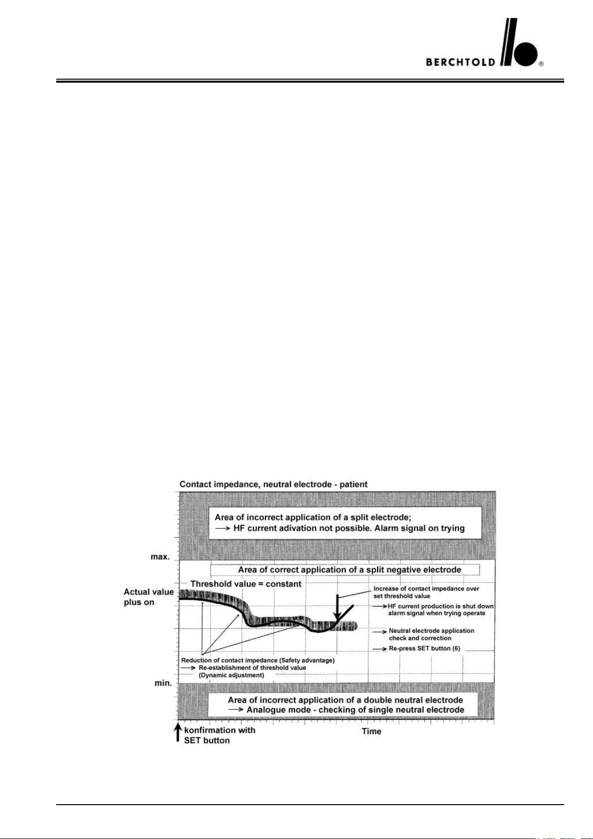
b) The use of split, negative electrodes
Split negative electrodes have two skin contact surfaces. When such electrodes are used in conjunction with
ELEKTROTOM® 610 not only is the correct connection of the negative electrode lead to the unit and the integrity of the cable checked but there is also a continual monitoring of the electrical contact quality between the patient and the electrosurgical unit.. A permanent signal is passed through the split electrode circuit and continually
compared with pre-establish maximum / minimum parameters. Following application of the negative electrode to
the patient, and connection of the connecting cable to the socket (23) in the electrosurgical unit, the SET button
(4) must be depressed to confirm the correct application of the neutral electrode. When all is correctly connected,
the red signal lamp (3) goes out and the symbol (1) is illuminated green to indicate that a split negative electrode is
applied. Simultaneously, the electrical impedance of the negative electrode circuit is measured and the maximum
and minimum permissible parameters are established.
There is a fully automatic and continual comparison made between the permissible maximum and minimum values and the originally established (or up-dated) permissible parameters.
Should the monitored patient contact impedance fall, there is a automatic re-establishment of the permissible parameters. (Acceptance of a lower impedance measurement is a safety feature of the ELEKTROTOM® 610 and is
referred to as Dynamic Adaptation).

14
ELEKTROTOM® 610 Service Manual
An increase of the monitored impedance, above the established maximum, is potentially dangerous and all HF
generation is immediately shut-down, an acoustic warning given and the error code „Err 1“ is displayed. The
application of the negative electrode, the integrity of the connecting cable and ist connection to the electrosurgical unit must then be investigated. Following the negative electrode investigation, and perhaps its re-application,
the SET button (4) must again be pressed The negative electrode circuit is thereby re-measured and the new,
maximum / minimum operating parameters are re-established. When the newly measured impedance falls within
the acceptable values dictated by the ELEKTROTOM® 610, the new maximum and minimum operating limits
are stored. All monopolar functions may then be safely used.
Should the actual impedance value, measured at any time, exceed the pre-established permissible maximum, the
red signal lamp (3) is illuminated, and the error code „Err 1“ is displayed. Re-pressing SET button (4) will not
cure the problem and the unit will remain inactive until the problem is found and rectified.
If the measured impedance value from a split negative electrode measures less than the pre-established minimum,
the electronics of the ELEKTROTOM® 610 recognise the electrode as a single (non-split) electrode and the
symbol (2), indicating the application of a single negative electrode, is illuminated on the control panel. This
situation can occur, for example, when the two plates are in contact with each other, or are electronically bridged
by a metallic object.
When using monopolar HF electrosurgical equipment, the correct application of a split negative electrode, on a
patients who is correctly isolated on the operating table, offers the highest degree of safety from accidental HF
electrosurgical burns.
8.4.3 Protection against unit malfunction
By monitoring the output current and voltage, the ELEKTROTOM® 610 makes a permanent comparison with
the limits of the selected values on the control panel. Should a disallowable discrepancy occur, HF generation is
immediately shut-down and the following error codes are displayed: Display 7 : „Err“ and on display 13: „8.“
8.4.4 Protection against erroneous unit settings
The control panel of the ELEKTROTOM® 610 has been designed as follows: clear, easy to understand symbols,
foil covered pressure (sensor) pads for unit function selection and three, up/down, pressure sensitive pads, to
pre-select unit output power. In order to offer a clear, over all, picture the panel is divided into four sections:
One concerning operational safety and three concerning unit function.
When selecting „MONO“ or „BI“ functions, the use of a double foot-switch in either monopolar or bipolar
mode is made available.
The following features are to be found just below the control panel: Mains switch (22), sockets (23), (24), 25),
and (26). These connecting sockets are all compatible with the BERCHTOLD range of monopolar and bipolar
accessories and electrosurgical instruments
15
ELEKTROTOM® 610 Service Manual
9.
Operating the ELEKTROTOM® 610
9.1 Puhs buttons, signal lights and symbols
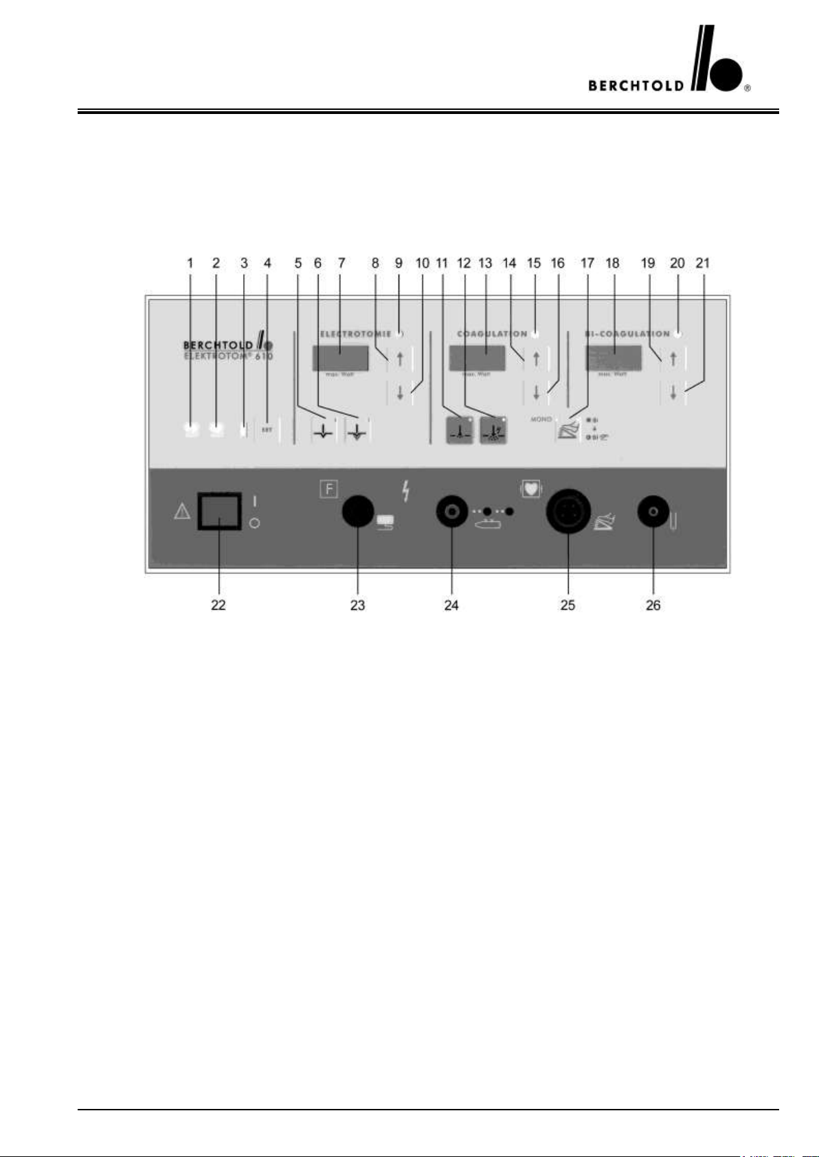
9.1.1 The front of the ELEKTROTOM® 610
1
Symbol indicating „split, negative electrode applied“
2
Symbol indicating „single, negative electrode applied“
3
Signal light red for negative electrode alarm
4
Pushbutton to confirm the correct application of a negative electrode (SET pushbutton)
5
Selection push button for cutting I
6
Selection push button for cutting II
7
Digital output indicator in Watts for cutting power
8
Push button to increase cutting output in 5 Watts steps
9
Signal lamp for cutting
10
Push button to decrease cutting output in 5 Watts steps
11
Selection push button for soft coagulation
12
Selection push button for forced coagulation
13
Digital output indicator in watts for coagulatory power
14
Push button to increase coagulating output in 5 Watts steps
15
Signal lamp for coagulation
16
Push button to decrease coagulating output in 5 Watts steps
17
Selection push button for double foot-switch use in either monopolar or bipolar coagulation
18
Digital output indicator in watts for bipolar coagulatory power
19
Push button to increase bipolar coagulating output in 5 Watts steps
20
Signal lamp for bipolar coagulation
21
Push button to decrease bipolar coagulating output in 5 Watts steps
22
Mains, on/off switch
23
Connecting socket for negative electrode (split or single)
24
Connecting socket for electrode handle (with additional socket for disposable handles)
25
Connecting socket for foot-switch
26
Connecting socket for bipolare coagulations instruments
16
ELEKTROTOM® 610 Service Manual
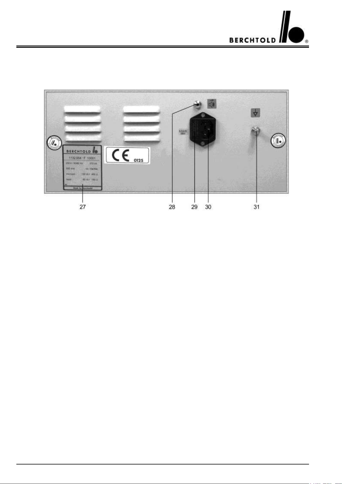
9.1.2 The rear of the ELEKTROTOM® 610
27
Plate showing unit number and mains information
28
Volume control,
recommended tool:
screwdriver with < 3 mm shaft diameter
29
Mains fuses F1 and F2 in removable housing
30
Connecting socket for mains cable
31
Connecting socket for earth potential balancing cable
 Loading...