

Berchtold Elektrotom 505 Service manual
ELEKTROTOM® 505
Service Manual (E)

ELEKTROTOM® 505 Service Manual (E)
CONTENSPAGE
1.Technical data2
2.Technical description3 - 4
2.1Power pack4
2.2Hand- and footpedal control4
2.3Frequency production4
2.4Output transformer4
2.5Indication for HF-current activation4
3.Function of the operating elements5
4.Explanation of the imprinted graphical symbols6 - 7
5.Lists of parts8 - 11
6.Wiring diagram12
7.Output diagrams13 - 15
8.Adjustment instructions and oscillograms16 - 23
2

ELEKTROTOM® 505 Service Manual (E)
1.TECHNICAL DATA
ELEKTROTOM® 505
Power requirements
Current consumption
Classification
Type
Nominal frequency
Impulse frequency of modulation
Observe duty cycles
Crest-factor ¹
Current type Spray-coagulation
Current type pure Cut / contact-coagulation
Current type Bi-coagulation
HF-output
110-220 V AC ±20 % reconnectable
max. 220 VA
1
monopolar output: BF
bipolar output: CF
500 kc/s
35 kc/s
10/30 ²
4,2
2,0
2,0
Current type Spray-coagulation
Current type pure Cut / contact-coagulation
Current type Bi-coagulation
Weight
Dimesions
Construction
Constructued
Leakage currents HF and LF
Certification:
Model registration01 / M – 169 / 91
¹ Crest factor describes the peak voltage in proportion to the nominal voltage
² Allow as much “ON” time to every “OFF” time
11 Watts ± 20 % at 2000 Ω
50 Watts ± 20 % at 1500 Ω
35 Watts ± 20 % at 100 Ω
3,8 kg
85 mm height
250 mm width
235 mm depth
All functional units assembled in modular
contruction, easily exchangeable.
according to IEC 601.
acc. to IEC 601-1 and 601-2-2
3

ELEKTROTOM® 505 Service Manual (E)
2.TECHNICAL DESCRIPTION
2.1 Power pack
The electric power supply of the unit results from a cold coupler socket with two mains fuses F 1 and F 2. The
mains transformer T 1 is supplied by a 2 – pole mains switch (with control lamp) S 1. A direct voltage is produced
from the 70 V winding of the transformer through the fuse F 4 and the rectifier V 6 which is smoothed with the
capacitor C 8. From the 12 V winding of the transformer a direct voltage is produced through the fuse F 3 and the
rectifier V 1, which is smoothed with the capacitor C 1.
2.2 Hand- and footpedal control
The hand- and footpedal control is electrically separated. It consists of a Meißner oscillator which is made of T 2,
V 5, V 4, R 2, R 8 and R 9. If the electrode, which is made for the finger switch or the footpedal switch, are activated, a corresponding signal is sent through the integrator C 5 and R 7 to the threshold switch (comperator) N 1
LM211, the output which switches the relay K 1.
2.3 Frequency production
N 2 UC 3524 is an integrated component for the pulse width control. The component produces an impulse variable in its width with the repetition rate of 500 kHz according to the control voltage at the input 2 which is adjusted with the HF-output control potentiometer R 13. The minimal output is adjusted with he spindle resistor R
15 and the maximum output is adjusted with the spindle resistor R 12. The driver phase consisting of V 10, V 8,
and V 9 is controlled by N 2. The output transformer consists of V 11m driver transformer T 3. V 12 and V 13. N
3 separator 74 HC 4040 produces the modulation frequency and the at the same time the audiofrequency.
The audiofreuqency is rectified with the transistor V 7 and can be changed with the trimming potentiometer R 24.
When FULGURATION is selected the fulguration impulse is connected to the Pin 10 and N 2. The drive pulse is
freed or blocked according to the modulation signal.
2.4 Output transformer
The power transistors V 12 and V 13 rectify the HF-signal which are fed to the driver V 11 and coupled-in
through the driver transformer T 3. The framework consisting of the diode V 15, the resistor R 35 and capacitor
C 19 prevents high voltages from the destroying the transistors V 12 and V 13. The resistors R 31 and R32 are the
protective measure against a too high dU/dt (voltage regulation speed). The incoupling of the HF-current is done
for cutting, coagulation and fulguration through the transformer T 5 and the capacitor C 24 and C 25. The uncoupling for the bipolar coagulation is done through the transformer T 4, the choke L 3 and the capacitor C 22 and
C 23.
The respective kind of current can be chosen with the spring switch S 2.
2.5 Indication pf the HF-current activation
If the HF-current is switched on, the transistor V 19 becomes conductive through the comperator C 20 and R 36.
The signal lamp H 1 shows red only with HF-current.
4

ELEKTROTOM® 505 Service Manual (E)
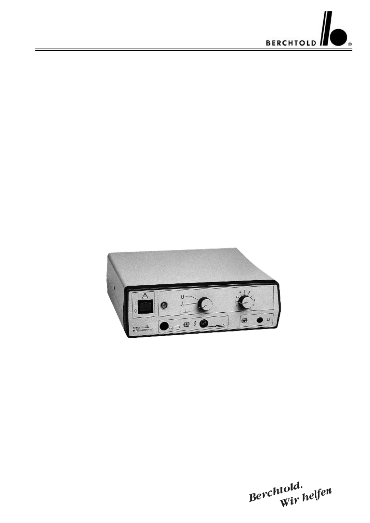
3.FUNCTION OF THE OPERATING ELEMENTS
1Mains-. ON amd OFF switch with signal lamp
2Signal lamp for HF activation
3Current monitoring switch
4Output regulator
5Socket for neutral electrode
6Socket for active electrode
7Socket for bi-coagulation
8Socket for one-pedal footswitch
9Socket for mains cable
10Plug for equipotential bonding
11Mains fuse F 1 (value see indication on unit)
12Mains fuse F 2 (value see indication on unit)
5
ELEKTROTOM® 505 Service Manual (E)
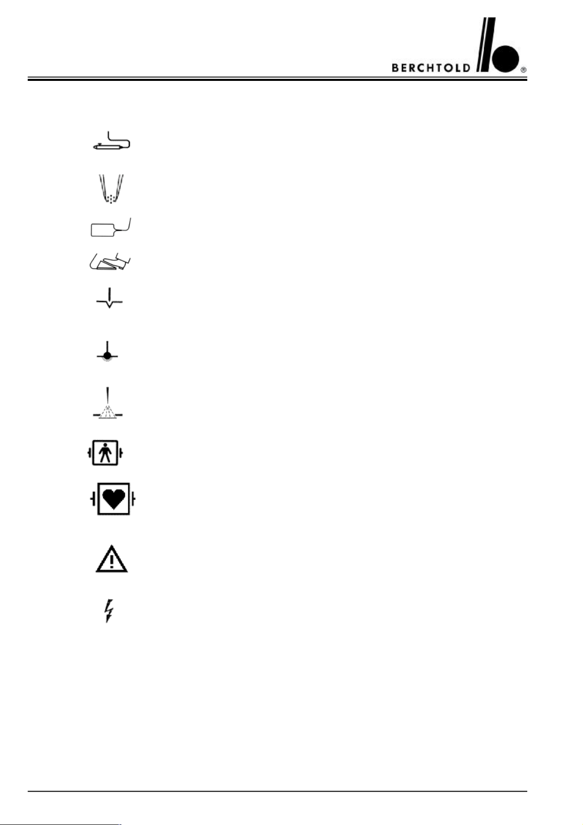
4.EXPLANATION OF THE IMPRINTED GRAPHICAL SYMBOLS
Connection for electrode handle with finger switch
Connection for bipolar coagulation
Connection for neutral electrode
Connection for footswitch
Non-modulated HF-current with high effective output at a low voltage
HF-current with high effective output for contact coagulation with ball
electrode or artery binder.
Very high modulated HF-current with very high voltage for spray-coagulation
(fulguration)
Symbol for classification of the unit into type BF. The unit is secured against
defibrillation.
Symbol for classification of the unit into type CF. The unit is secured against
defibrillation.
Advice: Attention for reading the instruction manual
High voltage
6

ELEKTROTOM® 505 Service Manual (E)
5.List of parts
DesignationDescriptionPart no.
B 1Modulator11353
C 1 Electrolyt capacitor 470 μF 25 V 41654
C 2 Elektrolyt capacitor 10 μF 25 V (RM 5) 44455
C 3Foil capacitor 100 nF (RM 5)44311
C 4Foil capacitor 100 nF (RM 5)44311
C 5Foil capacitor 100 nF (RM 5)44311
C 6Foil capacitor 100 nF (RM 5)44311
C 7Foil capacitor 100 nF (RM 5)44311
C 8 Elektrolyt capacitor 470 μF 200 V 9925
C 9Variable capacitor Ceramic envelope 330 pF 400 V11707
C 10Foil capacitor 100 nF (RM 5)44311
C 11Foil capacitor 100 nF (RM 5)44311
C 12Foil capacitor 100 nF (RM 5)44311
C 13 Multilayer capacitor 1 μF 63 V 9904
C 14Foil capacitor 10 nF 63 V5)44308
C 15Variable capacitor Ceramic envelope 2200 pF 400 V1038
C 16Mica capacitor 2500 pF 500 V1066
C 17Variable capacitor Ceramic envelope 2200 pF 400 V1038
C 18Mica capacitor 1000 pF 500 V1070
C 19 Foil capacitor 0,4 μF 630 V 1074
C 20Disk capacitor 10 nF 400 V45456
C 21Foil capacitor 10 nF 63 V44308
C 22Foil capacitor 4700 pF 250 V9588
C 23Disk capacitor 4700 pF 400 V41675
C 24Disk capacitor 1500 pF 400 V1033
C 25 Foil capacitor 0,022 μF 250 V 1071
C 26Foil capacitor 470 pF 100 V44149
F 1Fuse 1 A1738
F 2Fuse 1 A1738
F 3Subminiture fuse link 315 mA44490
F 4Subminiture fuse link 2,5 A50324
H 1Control lamp white 12 V50890
K 1Relay 12 V 2x44316
L 1Choke Type 407 1.2 mH48329
L 2 Chose 75 μH 10127
7

ELEKTROTOM® 505 Service Manual (E)
DesignationDescriptionPart no.
N 1Comparator Op.Amp. LM 21144508
N 2PWM UC 352442917
N 3Separator 74 HC 404048650
R 1Metalfilm resistor 4.7 kOhm 0,6 W1133
R 10Metalfilm resistor 47 kOhm 0,6 W1144
R 11Metalfilm resistor 220 kOhm 0,6 W1120
R 12Spindle resistor (standing) 25 k44390
R 13Potentiometer 5 kOhm 0.5 W50603
R 14Metalfilm resistor 1 kOhm44311
R 15Spindle resistor (standing) 5k42910
R 16Metalfilm resistor 10 kOhm 0.6 W1137
R 17Metalfilm resistor 6.8 kOhm 0.6 W1135
R 18Metalfilm resistor 3.3 kOhm 0.6 W1131
R 19Metalfilm resistor 100 Ohm 0.6 W1119
R 2Metalfilm resistor 2.2 kOhm 0.6 W1129
R 20Metalfilm resistor 2.2 kOhm 0.6 W1129
R 21Metalfilm resistor 1 kOhm 0.6 W1126
R 22Metalfilm resistor 3.3 kOhm 0.5 W1131
R 23Metalfilm resistor 1 kOhm 0.6 W1126
R 24Spindle resistor 50 k45559
R 25Metalfilm resistor 33 Ohm 0.6 W1206
R 26Vitreous enamelled wirewound resistor 10 kOhm 4.0 W9949
R 27Metalfilm resistor 4.7 Ohm 0.6 W1133
R 28Vitreous enamelled wirewound resistor 6.8 Ohm 17 W1172
R 29Vitreous enamelled wirewound resistor 6.8 Ohm 17 W1172
R 3Metalfilm resistor 1 kOhm 0.6 W1126
R 30Cement-coated wirewound resistor 2.2 Ohm 9 W1168
R 31Metalfilm resistor 10 Ohm 0.6 W1113
R 32Metalfilm resistor 10 Ohm 0.6 W1113
R 33Cement-coated wirewound resistor 2.2 Ohm 9 W1168
R 34Metalfilm resistor 120 kOhm 0.6 W44356
R 35Metal oxide film resistor 39 kOhm 4 W10294
R 36Metalfilm resistor 560 kOhm 0.6 W40881
R 37Metalfilm resistor 4.7 Ohm 0.6 W1133
R 38Metalfilm resistor 1 MOhm 0.6 W1106
R 39Metalfilm resistor 1 kOhm 0.6 W1126
8
 Loading...