

Berchtold Chromophare D-530Plus, Chromophare D-650Plus Preinstallation information
Pre-Installation Guide
®
CHROMOPHARE
D650 Plus & D530 Plus
Surgical and Examination Light
And Flat Panel Products
BERCHTOLD Corporation 1950 Hanahan Road Charleston, SC 29406
www.berchtoldusa.com
800-243-5135 · 843-569-6100 Fax: 843-569-6133
Part No. 70-000-0006, Rev.1

Table of Contents
G Introduction & General Information.....................................................3
G Superstructure Information.................................................................4-5
G Mounting Rings
L Mounting Ring (For New Construction)....................................6
L Universal Mounting Ring (For Existing Construction)...............7
G Electrical Requirements for Standard Mounting.................................8-9
G Electrical Requirements for Low Profile Mounting.............................. 10-11
G Electrical Requirements for Flat Panel Products................................12
G Wall Control Box Dimensions.............................................................13
G SK Box Dimensions............................................................................14
2 of 14
Part No. 70-000-0006, Rev. 1

Introduction & General Information
This Pre-Installation Guide details and describes the structural, mechanical and electrical
requirements of the room or site to allow proper installation of BERCHTOLD
CHROMOPHARE
It is intended for use by technical individuals involved in the specification, design and
construction of the room or site, such as architects, structural engineers, contractors,
electricians and pipe fitters.
The Hospital and/or its’ contractors are responsible for the preparation of the room or site
including the superstructure design and installation and all other mechanical and electrical
requirements described within this guide.
Painting and flooring need to be completed before the product can be installed.
Questions pertaining to the information contained in this guide can be addressed by calling
your local BERCHTOLD Techn ical Service Representative or BERCHTOLD Technical
Service at 1-800-243-5135.
This guide is applicable to the following BERCHTOLD products:
• CHROMOPHARE® D650 Plus
• CHROMOPHARE® D530 Plus
• All multiple combinations of the CHROMOPHARE® D650 Plus and D530 Plus.
• Stand alone Flat Panel Products
• Flat Panel combined with either one or two CHROMOPHARE
Plus lights.
®
Lights and Flat Panel products.
®
D650 Plus or D530
3 of 14
Part No. 70-000-0006, Rev. 1
Superstructure Design and Specification Information
The customer/contractor has
specifications. BERCHTOLD recommends that a Structural Engineer be involved in the
design of the superstructure.
Important: Weights and moments must be adjusted when designing for use in seismic
zones. Check with your local construction-engineering agency for applicable local and
state codes.
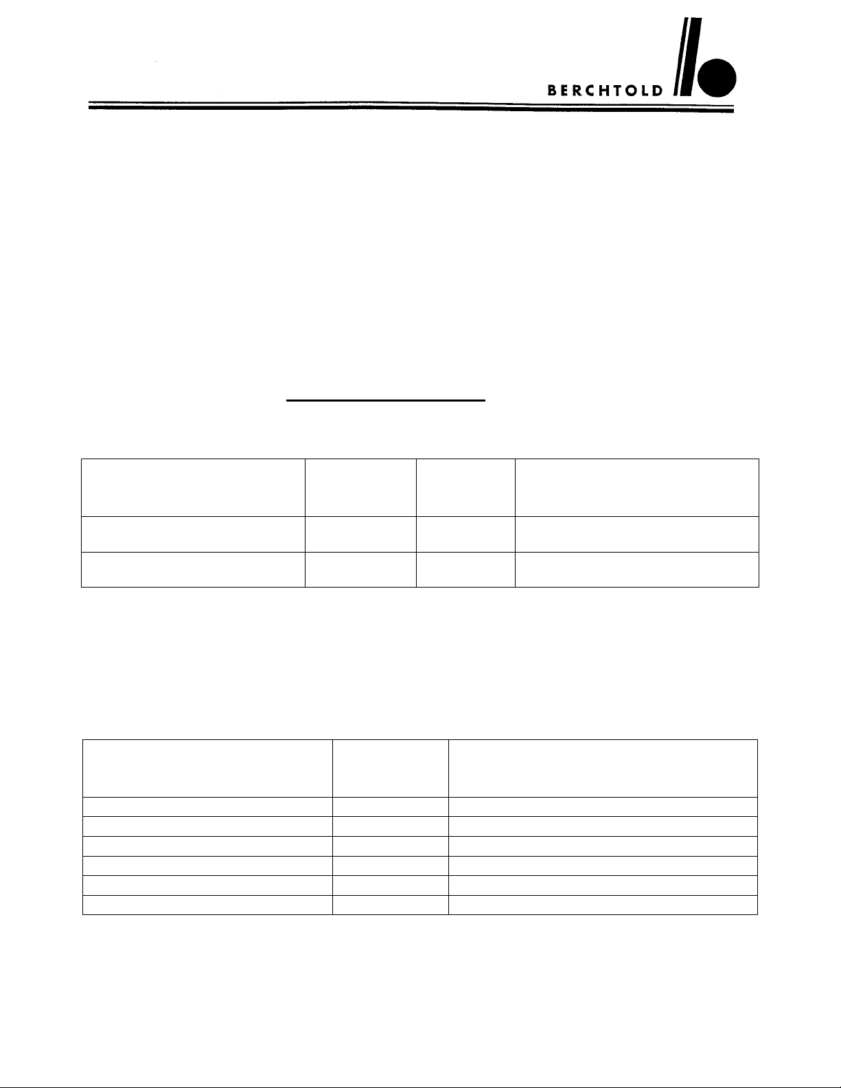
Recommended Design Specifications
BERCHTOLD Corporation STRONGLY recommends that the superstructure be designed
to meet the following specifications. (Reference drawing on next page). Designing to these
specifications will allow any Light or Flat Panel product to be hung from the structure.
Product Type
Any Light or Flat Panel
Non seismic zone
Any Light or Flat Panel
Seismic zone 4
Minimum Design Specifications by Product Type
If the customer decides to design the superstructure to the requirements of the specific
product type, the superstructure design specifications can be found in the table below.
Product Type
Single Light 114 360
Double Light 197 656
Triple Light 261 875
Flat Panel only 172 922
Single Light with Flat Panel 287 1180
Double Light with Flat Panel 369 1497
responsibility to ensure the superstructure design meets
Weight (T)
lbs.
Shear (V)
lbs.
ft•lbs with less than 0.1º
rotation at mounting ring
Moment (M)
369 N/A 1497
443 173 2453
Weight (T)
lbs.
ft•lbs with less than 0.1º rotation at
Moment (M)
mounting ring
4 of 14
Part No. 70-000-0006, Rev. 1
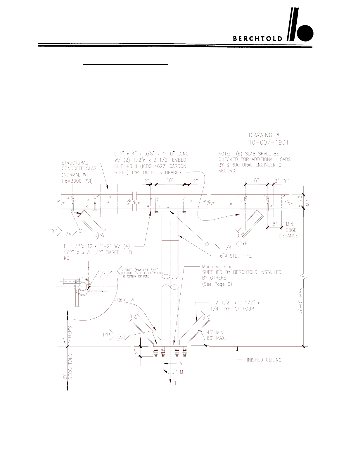
BERCHTOLD STRONGLY recommends that the superstructure be designed as shown.
Important design notes:
1. Four (4) kickers are needed.
2. Kickers should be anchored (welding preferred) to the mounting ring as shown in
Detail A. Do NOT anchor to vertical pipe.
3. The mounting ring (provided by BERCHTOLD, page 6) should be installed flush
with the ceiling with the studs pointing down.
Recommended Superstructure Design – See Specifications on Page 4
5 of 14
Part No. 70-000-0006, Rev. 1
 Loading...