

Berchtold Chromophare C950 Service manual
CHROMOPHARE® C 950
CHROMOPHARE
Service-Manual (D, E)
®
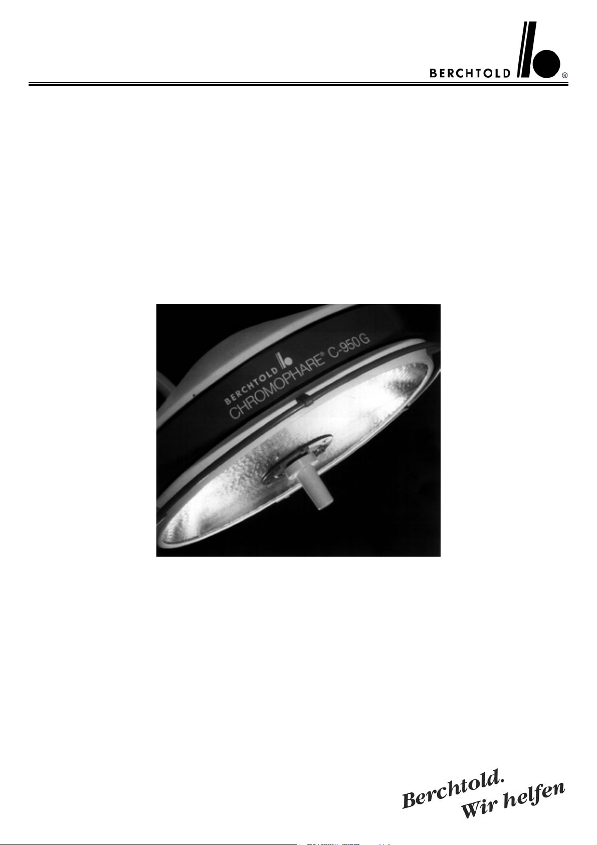
C 950 G

Inhaltsverzeichnis
für Service-Manual
C 950/C 950 G
Themen Seite
Einführung
Technische Daten 6
4 - 5
Schaltungsbeschreibung
Gültig bis ca. Serien Nr. 73.500
Schaltungsbeschreibung
Gültig ab ca. Serien Nr. 73.500
Ersatzteilliste 24 - 27
Bildliche Ersatzteildarstellung 28 - 43
Gültig von Serien Nr. 50.000 bis ca. 73.500
Gültig von ca. Serien Nr. 73.500 bis 150.000
Gültig von Serien Nr. 152.000 bis Fabrikationscode A, B, C
Gültig von Serien Nr. 73.500 bis Fabrikationscode A, B, C
Gültig für Autobloc-Ausführung
Gültig für LFN-Ausführung
Gültig für Standard-Ausführung
Serien Nr. 50.000 bis Fabrikationscode A, B, C
Gültig für Autobloc-Ausführung
Serien Nr. 50.000 bis Fabrikationscode A, B, C
Gültig für LFN-Ausführung
Serien Nr. 50.000 bis Fabrikationscode A, B, C
Gültig für alle Ausführungen
Meßpunkte – gültig von
ca. Serien Nr. 73.500 bis Fabrikationscode A, B, C 44
8 - 16
17 - 23
28 - 29
30 - 31
31 - 32
32 - 33
33
34
34 - 35
35 - 36
36 - 37
37 - 43
Einstellpunkte – gültig von
ca. Serien Nr. 73.500 bis Fabrikationscode A, B, C
Für Elektroniken mit der Kennzeichnung G und GR 45
Einstellpunkte – gültig von
ca. Serien Nr. 73.500 bis Fabrikationscode A, B, C
Für Elektroniken mit der Kennzeichnung G und GR
in Verbindung mit dem Diagnosestecker 46
Meßpunkte – gültig von
ca. Serien Nr. 50.000 bis Serien Nr. ca. 73.500 47
Einstellpunkte – gültig von
ca. Serien Nr. 50.000 bis Serien Nr. ca. 73.500 48
Einstellen des Gewichtsausgleichs 49 - 50
Einstellung der Federkennlinie 50 - 51
Anschlußplan für C 950 G/C 570
Transformatoren am Deckenrohr der Leuchte
Anschlußplan für C 950 G/C 570 Transformatoren und
Notstromumschaltrelais am Deckenrohr der Leuchte 53
Anschlußplan für C 950 G/C 570
Transformatoren separat im bauseitigem Wandschaltkasten 54
Anschlußplan für C 950 G/C 570 Transformatoren und Notstromumschaltrelais separat im bauseitigem Wandschaltkasten 55
52
Sicherungen 56
2
CHROMOPHARE® C 950/C 950 G Service Manual (D, E)

Table of contents
for Service-Manual
C 950/C 950 G
Contens Page
Introduction
Technical Data 7
4 - 5
Functional Description
valid up to approx. Serial no. 73.500 8 - 16
Functional Description
valid from approx. Serial no. 152.000 17 - 23
Spare Part List 24 - 27
Graphic spare part description 28 - 43
Valid from serial no. 50.000 up to approx 73.500
Valid from approx. serial no. 73.500 up to 150.000
Valid from serial no. 152.000 up to manufacturing code A, B, C
Valid from approx. serial no. 73.500
up to manufacturing code A, B, C
Valid for Autobloc-Version
Valid for LFN-Version
Valid for Standard-Version
serial no. 50.000 up to manufacturing code A, B, C
Valid for Autobloc-Version
serial no. 50.000 up to manufacturing code A, B, C
Valid for LFN-Version
serial no. 50.000 up to manufacturing code A, B, C
Valid for all types
Measuring Points – valid from
approx. serial no. 73.000 up to fabrication code A, B, C 44
28 - 29
30 - 31
31 - 32
32 - 33
33
34
34 - 35
35 - 36
36 - 37
37 - 43
Adjustment Points – valid from
approx. serial no. 73.000 up to fabrication code A, B, C
For electronics with marking G and GR 45
Adjustment points – valid from
approx. serial no. 73.500 up to fabrication code A, B, C
For electronics with marking G and GR
by use of diagnostic plug 46
Measuring Points – valid from
approx. serial no. 50.000 up to serial no. 73.500 47
Adjustment points – valid from
serial no. 50.000 up to serial no. 73.500 48
Adjusting the Weight Counter Balance 49 - 50
Adjustment of the Spring Characteristic 50 - 51
Electrical Diagram for C 950 G/C 570
Transformers mounted on the ceiling tube 52
Electrical Diagram for C 950 G/C 570
Transformers and emergency relays mounted on the ceiling tube 53
Electrical Diagram for C 950 G/C 570
Transformers mounted in a wall box on side of building 54
Electrical Diagram for C 950 G /C 570 Transformers and emergency
relais mounted in a wall box on side of building 55
Fuses 56
CHROMOPHARE® C 950/C 950 G Service Manual (D, E)
3

Einführung
Introduction
Die Berchtold CHROMOPHARE® ist eine
moderne Operationsleuchte mit wesentlichen technischen Neuerungen.
Durch Anwendung moderner Elektronik,
einem computerberechneten Polygonreflektor, einer leichtgängigen Kreisfahrbahn mit
kardanischer Aufhängung des Leuchtenkörpers werden viele Vorteile geboten.
• hohe Schattenfreiheit im Operationsfeld
• hohe Beleuchtungsstärke auch im tiefliegenden Operationsfeld durch einen als Mittelscheinwerfer wirkenden Zusatzreflektor
• sichere Hygiene durch glatte Außenflächen
ohne vorstehende Bedienungselemente und
luftdichtem Abschluß des Leuchtenkörpers
• großer Bereich der Höhenverstellung
• Bedienung außerhalb der steilen Zone an
einem Tastenfeld unterhalb des außenliegenden Federgelenks
Funktionen:
- Ein/Aus
- Fokusverstellung
- Helligkeitsverstellung mit Anzeige über ein
Leuchtband
- Helligkeit wird nach Aus- und Einschalten
wieder auf den vorherigen Wert eingestellt
Prüfung der Reservelampe auf
Funktionstüchtigkeit
- Stop-Funktion des Autobloc und der
Lichtfeldnachführung mit Anzeige
- Anzeige bei Ausfall der Hauptlampe
• Die Helligkeit ist geregelt, d.h. unabhängig
von eventuellen Schwankungen von Netzspannung oder -last wird die Helligkeit bei
jeder eingestellten Beleuchtungsstärkestufe
konstant gehalten.
• Autobloc-System. Alle Drehgelenke werden durch Magnetbremsen gebremst. Die
Magnetbremsen werden durch eine Steuerelektronik beim Berühren des umlaufendenHandgriffs oder des zentralen Handgriffs
automatisch gelöst. Dadurch ergibt sich eine
sehr gute Beweglichkeit des Leuchtenkörpers und eine exakte Einstellung des Lichtfelds.
The Berchtold CHROMOPHARE® is the
latest in the new generation of surgical lights,
and features many new technological advances.
Many advantages are offered by utilizing the
latest electronic techniques, a computer designed polygon-reflektor, and cardanic suspension of the light head.
• shadow- free to a high degree within the
operating area
• high illumination even in deep operating
areas provided by an additional reflector
which functions as a central spot light
• ensured hygienic conditions due to smooth
outher surfaces without protruding control
elements and air-tight light head sealing
• large vertical adjustment range
• functions controlled from outside of the
sterile zone via a touch pad control panel
located unter the outer springbalanced joint
Functions:
- on/off
- focus adjustment
- light intensity control with display by means
of a luminous band
- intensity is set to the previous value after
light has been switched off and on again
- reserve lamp is checked for proper functioning
- stop function of the Autobloc and light
field guidance systems with indicator
- indicator for failure of the main lamp
• Light intensity is regulated, i.e. independently of possible fluctuations is the supply
voltage or load, light intensity is maintained
regardless of set illumination level
• Autobloc System. All revolving joints are
braked by means of magnetic brakes. Control
electronics release the magnetic brakes automatically when the rail around the light head
or the centrally installed hand grip is touched.
This provides maximum mobility of the light
head and enables precision adjustment limitation.
4
CHROMOPHARE® C 950/C 950 G Service Manual (D, E)

• Die Operationsleuchte kann sowohl an
Wechselspannung (wird gleichgerichtet), wie
auch an Gleichspannung betrieben werden,
ohne daß damit eine Funktionseinbuße verbunden wäre.
• Lichtfeld-Nachführung. Mit Hilfe einer
opto-elektronischen Fernsteuerung mit großem Lichtfeld genau auf den gewünschten
Punkt einstellen. Die Führung des Lichtfeldes geschieht ohne Berührung der Leuchte
durch den sterilen "Light-Pilot", der vom
Operateur auf den von ihm gewünschten
Punkt geführt wird.
• Der Austausch von defekten Halogenlampen kann vom Pflegepersonal selbst ohne
Werkzeug vorgenommen werden.
Der mechanische Aufbau und die Funktion
der elektronischen Schaltkreise werden auf
den folgenden Seiten detailliert beschrieben.
• The operation light can be operated on
alternating voltage (is rectified), as well as
direct voltage without functional limitation.
• Light field guidance. By means of optoelectronic remote control with a large view finder
field, the operating surgeon can adjust the
light field himself exactly as needed. The light
field is guided without touching the light
itself by means of the sterile "Light Pilot",
held by the surgeon and guided to the point
desired by the surgeon.
• Defect halogen lamps can be exchanged by
the medical assistants themselves; no tools
are necessary.
Mechanical design and electronic switching
circuits are described in detail on the following pages.
CHROMOPHARE® C 950/C 950 G Service Manual (D, E)
5

Technische Daten Berchtold CHROMOPHARE® Operationsleuchte C 950/C 950 G
Operationsleuchte Berchtold CHROMOPHARE® C 950
Elektrische Anschlußdaten Trafo 110-120/220-240 Volt, 360 VA
Beleuchtungsstärke in 1 m Abstand
bei Farbtemperatur 4.500 K 105.000 Lux
bei Farbtemperatur 3.600 K 140.000 Lux
Durchmesser des Polygon-Reflektors 870 mm
Durchmesser des Leuchtengehäuses 950 mm
Licht-Austrittsfläche 90 % der Leuchten-Unterseite
Durchmesser kleines Lichtfeld 200 mm
Durchmesser großes Lichtfeld 350 mm
Lichtfeld-Verstellung stufenlos mit Servomotor
Gleichbleibender Lichtfeld-Durchmesser ohne Nachfokussierung konstant bis 500 mm Höhen-Differenz
Hauptlichtquelle 1 Halogenlampe 250 Watt / 24 V, Artikel Nr. CZ 907-24
Reservelichtquelle 1 Halogenlampe 250 Watt / 24 V, Artikel Nr. CZ 907-24
Automatische Umschaltung auf Reservelicht bei Defekt der Hauptlichtquelle mit optischer Anzeige
Mittlere Lebensdauer der Halogenlampe ca. 1000 Brennstunden
Aktionsradius der Fahrbahn 1950 mm
Höhenverstellung des Leuchtenkörpers 1150 mm
Elektrik entsprechend den Sicherheitsstandards-Standards nach VDE und IEC
Operationsleuchte Berchtold CHROMOPHARE® C 950 G
Elektrische Anschlußdaten Trafo 110/115/120/220/230/240 Volt, 450 VA
Gleichspannung 24,4 V - 30,0 V/max. 16 A
Wechselspannung 23 V - 30 V ~
Beleuchtungsstärke in 1 m Abstand
bei Farbtemperatur 4.500 K 105.000 Lux
bei Farbtemperatur 3.600 K 140.000 Lux
Durchmesser des Polygon-Reflektors 870 mm
Durchmesser des Leuchtengehäuses 950 mm
Licht-Austrittsfläche 90 % der Leuchten-Unterseite
Durchmesser kleines Lichtfeld 200 mm
Durchmesser großes Lichtfeld 350 mm
Lichtfeld-Verstellung stufenlos mit Servomotor
Gleichbleibender Lichtfeld-Durchmesser ohne Nachfokussierung konstant bis 500 mm Höhen-Differenz
Hauptlichtquelle 1 Halogenlampe 250 Watt / 22,8 V, Artikel Nr. CZ 907-22
Reservelichtquelle 1 Halogenlampe 250 Watt / 22,8 V, Artikel Nr. CZ 907-22
Automatische Umschaltung auf Reservelicht bei Defekt der Hauptlichtquelle mit optischer Anzeige
Mittlere Lebensdauer der Halogenlampe ca. 1000 Brennstunden
Aktionsradius der Fahrbahn 1950 mm
Höhenverstellung des Leuchtenkörpers 1150 mm
Elektrik entsprechend den Sicherheitsstandards-Standards nach VDE und IEC
6
CHROMOPHARE® C 950/C 950 G Service Manual (D, E)

Technical Data Berchtold CHROMOPHARE® Surgical Lights C 950/C 950 G
Berchtold CHROMOPHARE® Surgical Lights C 950
Power requirements Transformer 110-120 /220-240 Volt, 360 VA
Illuminance measured at 1 m distance:
with colour temperature 4.500 K 105.000 Lux
with colour temperature 3.600 K 140.000 Lux
Diameter of polygon reflectors 870 mm
Diameter of lamp housing 950 mm
Light emission surface 90 % of light underside
Diameter of small light field 200 mm
Diameter of large light field 350 mm
Light field adjustment infinitely variable with servomotor
Constant light field diameter without focussing constant up to 500 mm difference in height
Main light source 250 Watt / 24 V, article no. CZ 907-24
Reserve light source 250 Watt / 24 V, article no. CZ 907-24
Automatic switching of reserve lamp with visual indication
Average service life of halogen lamp approx. 1000 hours
Swivel radius of lamp housing 1950 mm
Height adjustment of light head 1150 mm
Electrical system in accordance with VDE and IEC standards
Berchtold CHROMOPHARE® Surgical Lights C 950 G
Power requirements Transformer 110/115/120/220/230/240 V, 450 VA
Direct voltage 24,4 V - 30,0 V/max. 16 A
Alternating voltage 23 V - 30 V ~
Illuminance measured at 1 m distance:
with colour temperature 4.500 K 105.000 Lux
with colour temperature 3.600 K 140.000 Lux
Diameter of polygon reflectors 870 mm
Diameter of lamp housing 950 mm
Light emission surface 90 % of light underside
Diameter of small light field 200 mm
Diameter of large light field 350 mm
Light field adjustment infinitely variable with servomotor
Constant light field diameter without focussing constant up to 500 mm difference in height
Main light source 250 Watt / 22,8 V, article no. CZ 907-22
Reserve light source 250 Watt / 22,8 V, article no. CZ 907-22
Automatic switching of reserve lamp with visual indication
Average service life of halogen lamp approx. 1000 hours
Swivel radius of lamp housing 1950 mm
Height adjustment of lamp housing 1150 mm
Electrical system in accordance with VDE and IEC standards
CHROMOPHARE® C 950/C 950 G Service Manual (D, E)
7

Schaltungsbeschreibung der
Berchtold
CHROMOPHARE®
Operationsleuchte
C 950 Gültig bis ca.
Serien Nr. 73.500
Functional Description of the
Berchtold
®
CHROMOPHARE
C 950 Operating Light
valid up to approx.
serial no. 73.500
Transformator und NotstromUmschaltung:
Die Netzspannung wird über einen
Hauptschalter über die Netzsicherungen F 12 und F 13 an den Transformator T 2 gelegt. Es liegt dann Spannung an Relais K 13, das durch die
Sicherung F 18 abgesichert wird. Relais K 13 wird aktiviert und schaltet
die Betriebsspannung aus der Sekundärwicklung des Transformators T 2
an die Operationsleuchte. Die Leuchten-Betriebsspannung ist durch die
Sicherungen F 16 und F 17 abgesichert.
Bei Ausfall der Netzspannung geht
das Relais K 13 in Ruhestellung zurück, über die Ruhekontakte des Relais K 13 wird die Notstromversorgung an die Leuchte geschaltet. Die
Notstrom-Spannung wird durch die
Sicherungen F 14 und F 15 abgesichert.
Ein/Aus-Schaltung der Leuchte:
Die über die Kontakte X 1 und X 2
auf Platine 3 zugeführte Betriebsspannung wird mit Brückengleichrichter V 40 gleichgerichtet und mit Kondensator C 30 geglättet. Mit dieser
Gleichspannung werden die bistabilen
Relais K 1 und K 2 versorgt. Wird
über S 6 (Ein-Taste) die Spule I von
Relais K 1 erregt, schaltet Kontakt K
1 die Leuchte ein und der Restmagnetismus im Relaiskern von K1 hält den
Kontakt K 1 geschlossen. Wird über S
5 (Aus-Taste) die Spule II von K 1
erregt, schaltet Kontakt K1 die Leuchte aus, der Restmagnetismus in Spule I
wird dabei durch den in Spule II fließenden Strom aufgehoben. Dieser
Stromkreis ist mit Sicherung F 1 abgesichert.
Schaltung für die Leucht-Anzeige der
eingestellten Beleuchtungsstärke und
die Regelung der Beleuchtungsstärke:
Transformers and Emergency Power
Switch Over:
When the power is switch on, the
voltage is supplied to the transformer
T 2 via the power fuses F 12 and F 13
and current is then sent to relay K 13,
which is protected by the fuse F 18.
Relay K 13 is activated and switches
on the contacts of the transformer
T2´s secondary circuit, which
switches on the light. Circuit to bulb is
protected by fuses F 16 and F 17.
Should the power supply fail, relay
K 13 switches into the off position.
The emergency power supply is then
switched on to the light through the
normally closed contacts of relay K13.
Emergency voltage is protected by the
F 14 ans F 15 fuses.
On/Off Switching of the Light:
The operating voltage, which is supplied to contacts X 1 and X 2 on circuit board 3, is rectified with bridge
connected rectifier V 40, and flattened
with the C 30 capacitor. The bi-stable
relays K 1 und K 2 are supplied by
this D.C. voltage. If the coil I of relay
K1 is activated by the S 6 (ON
switch), the light is switched on by
contact K1 and the residual magnetism in the relay core of K 1 holds the
K 1 contact closed. When coil II of K
1 is activated by the S 5 (OFF switch),
then contact K 1 shuts off the light,
the residual magnetism in coil I is
deactivated by the energy flowing
through coil II. Voltage is protected
by fuse F 1.
Switching Mechanism for the Light
Display Board. activated light, and
light intensity regulator:
8
CHROMOPHARE® C 950/C 950 G Service Manual (D, E)

Ist die Leuchte eingeschaltet, wird die
Betriebsspannung auf Platine 15 mit
den Dioden V 13, V 14, V 15 und V
16 gleichgerichtet und mit Kondensator C 12 auf der Platine 1 geglättet.
Diese Gleichspannung wird mit Transistor V 20 auf Platine 1 und den
Spannungsregler IC 4 auf den am
Trimmerwiderstand R 32 eingestellten
Spannungswert stabilisiert. Diese
Spannung am Emitter von Transistor
V 20 beträgt 12 V. Eine weitere Versorgungsspannung für die Regelung
der Beleuchtungsstärke wird von IC 8
auf 5 Volt eingestellt. Die Drossel L
1und die Kondensatoren C 10 und C
11 sind für den Störungsschutz eingebaut. Diese Spannungsversorgung ist
durch Sicherung F 3 auf Platine 1
abgesichert.
Wird S 1 (Beleuchtungsstärke geringer) bei eingeschalteter Leuchte gedrückt, wird Relais K 8 eingeschaltet
und der Zähler IC 11 (Platine 5) erhält über die Verknüpfungsglieder IC
9 und IC 10 ein Low-Signal auf Pin 4
(Down). Dadurch wird an den Dezimaldekodern IC 12 und IC 13 die
nächst niedrigere Helligkeitsstufe
durchgeschaltet.
Ist die niedrigste Helligkeitsstufe erreicht, wird parallel zur Leuchtanzeige
H3 der Optokoppler OK 3 angesteuert. Der Transistor von OK 3 sperrt
über die Verknüpfungs- glieder IC 9
und IC 10 ein weiteres Low-Signal auf
Pin 4 des Zählers IC 11.
Wird S 2(Beleuchtungsstärke höher)
gedrückt, wird Relais K7 erregt und
der Zähler IC 11 erhält über die Verknüpfungsglieder IC 9 und IC 10 ein
Low-Signal auf Pin 6 (up). Dadurch
wird an den Dezimaldekodern IC 12
und IC 13 die nächst höhere Stufe
durchgeschaltet.
Ist die höchste Helligkeitsstufe erreicht (Stufe 7), wird parallel zur
Leuchtanzeige H 3 der Optokoppler
OK 4 angesteuert. Der Transistor von
OK 4 sperrt über die Verknüpfungsglieder IC 9 und IC 10 ein weiteres
Low-Signal auf Pin 5 (up) des Zählers
IC 11.
If the light is on, then the line voltage
on Cirucuit Board 15 is rectified with
V 13, 14, 15 and 16 diodes and flattened (planed) with capacitor C 12 on
circuit board 1. This D.C. voltage is
stabilized, with transistor V 20 on
plate 1 and the voltage regulator IC 4,
to the voltage output adjusted on
trimmer resistor R 32. This voltage on
the emitter of transistor V 20 carries
12 Volts. Another supply voltage for
the regulation of light intensity is set to
5 volts by IC 8. The reactive coil L 1
and capacitors C 10 and 11 are built in
for protection against malfunctions.
The power supply is protected by fuse
F 3 on circuit board 1
When the light is on, and S 1 (lowering
of light intensity) is activated, then
relay K 8 is turned on and the counter
IC 11 (Circuit Board 5) receives a low
signal on pin 4, by way of IC 9 and 10.
This way, the next lowest light intensity level on the decimal decoders IC
12 and 13 is switched on.
When the lowest light intensity level is
reached, both the light display H 3 and
the opto coil OK 3 are activated. OK
3´s transistor blocks a further
low signal on pin 4 of the counter IC
11, by way of IC 9 and 10.
When S 2 (increasing light intensity) is
pressed, relay K 7 is activated and the
counter IC 11 receives a low signal on
pin 5 (UP) by way of switching elements IC 9 and 10. This way the next
highest light intensity level on the
decimal decoders IC 12 and 13 is
switched on.
When the highest level is reached
(level 7), the opto coil OK 4 is run
parallel to light display H 3. The transistor of OK 4 blocks a further low
signal by way of IC 9 and IC 10 on pin
5 of the IC 11 counter.
CHROMOPHARE® C 950/C 950 G Service Manual (D, E)
9

Durch das RC-Glied R 25, R 26 und C 9
wird bewirkt, daß der Zähler IC 11 beim
Einschalten der Leuchte auf Stufe 1
gesetzt wird. Drossel L 2 und Varistor R
46 verhindern Störeinflüsse auf den
Zähler IC 11.
Der Dezimaldekoder IC 12 schaltet
jeweils einen der 7 Leuchtdioden-Balken
von Leuchtanzeige H 3 auf Minus.
Durch R 14 wird der Strom in H 3 begrenzt.
Die von der Operationsleuchte abgegebene Beleuchtungsstärke ist von der an
die Halogenlampe H 1 angelegten Effektivspannung wird über den Triac V 8 auf
Platine 3 geregelt.
Die Ansteuerung des Triac V 8:
Der Dezimaldekoder IC 13 auf Platine 5
legt jeweils einen der Trimmerwiderstände R 15 bis R 21 an Minus. Diese
Trimmerwiderstände sind den Helligkeitsstufen zugeordnet: R 15 für Stufe
1.... R 21 für Stufe 7. Mit diesen Trim-
merwiderständen kann die Helligkeit der
Leuchtdiode in Optokoppler OK 2 eingestellt werden. Der Transistor des Optokopplers OK 2 regelt die Spannung
am Steuereingang von IC 3 (Pin 11). IC
3 ist eine integrierte PhasenanschnittSteuerung für den Triac V 8. Je höher
der Spannungswert an Pin 11 von IC 3
ist, um so später zündet nach dem Nulldurchgang einer Halbwelle der Wechselspannung für die Halogenlampe H 1 der
Triac V 8 und um so niedriger ist dann
der Effektivwert dieser Wechselspannung (die Lampe wird dunkler). Widerstand R 8, Diode V 9 Z-Diode
V 10 und Kondensator C 6 versorgen IC
3 mit einer stabilisierten Gleichspannung
von 12 Volt. Über R 9 erhält IC 3 das
Signal des Nulldurchgangs der am Triac
V 8 anliegenden Wechselspannung. R 11
begrenzt den positiven Triggerimpuls
auf Triac V 8. R 10 und C 7 bilden einen
Rampengenerator. Steigt die Rampenspannung an C 7 über den Wert der
Steuerspannung an Pin 11 von IC 3 und
der Triac V 8 wird gezündet.
Trough the RC circuit R 25, 26 and C 9,
the IC 11 meter automatically is set on
level 1 when the light is turned on. Reactive coil L 2 and varistor R 46 prevent
interferences from affecting IC 11.
The decimal decoder IC 12 switches one
of the 7 light diodes from the light indicator panel H 3 to minus. R 14 limits the
power flow in H 3.
The light intensity given off from the
operating light is dependent on the effective voltage activating halogen bulb H
1. This effective voltage is regulated by
the triac V 8 on cirucuit board 3.
The Drive of Triac V 8:
The decimal decoder IC 13 on Circuit
Board switches on of the present resistors R 15 trough R 21 on minus. These
trimmer resistors are paired to the 7 light
intensity levels: R 15 for level 1 .... R 21
for level 7. With these trimmer resistors,
the brightness of the light diode in opto
coil OK 2 can be set. The transistor of
the opto coil OK 2 controls the voltage
going through the control entrance of IC
3 (pin 11). IC 3 is a phase controller for
the Triac V 8. Triac V 8 activates after
the crossover of a half wave of alternating voltage going to halogen bulb H 3.
The higher the voltage level on pin 11 of
IC 3 is, the later the Traic V 8 is activated, and the lower is the effective
value of the alternating voltage (the lamp
darkens).Resistor R 8, diode V 9, Z diode V 10 and capacitor C 6 supply IC 3
with a stable, D.C. voltage of 12 Volts.
Through R 9, IC 3 receives the signal
that the crossover of A.C. current on
Triac V 8 has occured. R 11 limits the
positive trigger to Triac V 8. R 10 and C
7 form a ramp generator. If the value of
the ramp voltage on C 7 climb higher
than the control voltage on pin 11 of
IC3, the Triac V 8 activates.
10
CHROMOPHARE® C 950/C 950 G Service Manual (D, E)

Beträgt die Steuerspannung 0 V,erhält
die Halogenlampe H 1 die volle Wechselstrom-Halbwelle und leuchtet mit
maximaler Helligkeit. Bei einem eventuellen Kurzschluß der Halogenlampe wird
die Steuerelektronik durch die Sicherung
F 2 geschützt.
Schutzschaltung für Triac V 8 und Steuerung für Warnanzeige:
Um bei einem Defekt der Helligkeitsregelung oder bei Netzausfall und Übergang der Leuchten-Spannungsversorgung auf Notstrom mit Gleichspannung den Ausfall der Leuchte zu
verhindern, werden die Funktionen der
Helligkeitsregelung und des Triac mit
der Schaltung auf Platine 4 kontrolliert.
Die Spannungsversorgung erfolgt über
den Brückengleichrichter V 1 und Kondensator C 1 auf Platine 1, die von IC 1
auf Platine 1 mit 24 Volt stabilisiert wird.
Der Schwellwertschalter IC 2 erhält über
Widerstand R 2 eine Spannung aus dem
Spannungsteiler R 3, R 4 und R 5. Über
den Brückengleichrichter V 7, Widerstand R 7 und Optokoppler OK 1 wird
diese Spannung durch den Spannungsabfall am Triac V 8 beeinflußt. Steigt der
Spannungsabfall am Triac über einen
eingestellten Schwellwert, d. h., daß
entweder die Halogenlampe zu dunkel
oder gar nicht leuchtet oder, daß wegen
Netzausfall die Betriebsspannung für die
Leuchte auf Gleichspannung umgeschaltet hat und der Triac diese Gleichspannung sperrt, sinkt über den Transistor in
Optokoppler OK 1 die Spannung am
Spannungsteiler R 3, R 4 und R 5 und
der Ausgangstransistor (Kollektor an Pin
5, Emitter an Minus) mit Schwellwertschalter IC 2 geht in den Sperrzustand
über. Dadurch wird Transistor V 6 leitend, Relais K 4 zieht an und bleibt
durch einen Selbsthaltekontakt angezogen. Parallel zu Relais K 4 zieht auch
Relais K 3 an und bleibt ebenfalls in
diesem Zustand. Der Kontakt von Relais
K 3 überbrückt nun den Triac V 8.
If the control voltage carries zero volts,
then Halogen bulb H 1 receives the full
crossover of half wave A.C., for maximum light intensity. Should an electrical
short circuit occur on the halogen bulb,
fuse F 2 protects the electronic controls.
Protective Cirucuit for Triac V 8 and
Control of the Warning Signal:
Should a defect in the light intensity
regulator occur or should there be a
power failure and the lamp be switched
over the emergency power supply with
D.C., in order to pervent the light from
becoming inoperational, the functions of
the light intensity regulator and those of
the Triac are controlled by the switch on
Circuit Board 4.
Voltage is supplied over bridge connected rectifier V 1 and capacitor C 1 on
Circuit Board 1, which is stabilized to 24
Volts by IC 1 on Circuit Board 1.
The threshold switch IC 2 receives voltage out of the R 3, 4, 5 distributors,
through bridge connected rectifier V 7,
resistor R 7 and opto coil OK 1. This
voltage is influenced by the voltage drop
in Triac V 8. When the voltage drops to
a set low point (the halogen bulb is too
dark or does not light), or due to power
failure the line voltage switches to D.C.
voltage and Triac blocks this voltage,
then the voltage on the distributors R 3,
R 4 and R 5 lowers by way of the transistor in opto coil OK 1, and the output
transistor (collector on pin 5, emitter on
minus) in the threshold detector IC 2
switches to off. In this way, transistor V
6 activates relay K 4, which stays on due
to its self locking contact. Simultaneously, relay K 3 activates and stays
locked. The contact from relay K 3
shorts out the Triac V8.
CHROMOPHARE® C 950/C 950 G Service Manual (D, E)
11

Die Halogenlampe H 1 leuchtet nun mit
voller Helligkeit. Relais K 4 schaltet
zusätzlich IC 7 an die Spannungsversorgung der Leuchtanzeige H 1 auf den
vorgeschriebenenNennwert begrenzt.
Der Schwellwert für IC 2 und damit die
Empfindlichkeit der vorstehend beschriebenen Schaltung wird am Trimmerwiderstand R 5 eingestellt. Kondensator C 4 verhindert, daß beim Einschalten der Leuchte (in diesem Moment
leuchtet die Halogenlampe noch nicht
oder noch nicht mit voller Helligkeit) die
Schaltung anspricht. Beim Ausschalten
der Leuchte erhält die Leuchtanzeige H
1 einen kurzen Stromstoß und blinkt
kurz auf. Dies ist dann gleichzeitig eine
Funktionskontrolle für die Schaltung.
Steuerung der Focus-Verstellung
(Platine 7):
Wird Taste S 4 auf Platine 16 (Signal für
kleineren Lichtfeld 0) gedrückt, zieht
Relais K 5 an und der Antriebsmotor für
die Focusverstellung dreht sich im
Rechtslauf. Dabei wird gleichzeitig über
Relaiskontakt K 5 das Relais K 6 verriegelt.
Wird Taste S 3 auf Platine 16 (Signal für
größeren Lichtfeld 0) gedrückt, zieht
Relais K 6 an und der Antriebsmotor für
die Focusverstellung dreht sich im
Linkslauf. Gleichzeitig wird dabei über
den Relaiskontakt
K6 das Relais K5 verriegelt
Die Entstörung des Antriebsmotors M 1
erfolgt durch Kondensator C 13 auf
Platine 9.
Elektronik für automatische Reservelicht-Einschaltung (Platine 9).
Die an die Platine gelegte BetriebsWechselspannung wird mit Brückengleichrichter V 24 gleichgerichtet und
mit Kondensator C 14 geglättet. Spannungsregler IC 14 stabilisiert diese
Gleichspannung auf 24 Volt. C 15 und C
16 verhindern Störeinflüsse auf IC 14.
The halogen bulb now lights with full
intensity. Relay K 4 also switches IC 7
on, which supplies power to the light
display H1. This display (electronics
defective or shut off) receives voltage by
way of transistor V 21 and it begins to
blink in a rhythm of approx. 3 Hz. R 27
controls the current running through H
1 to its requested nominal value.
The threshold for IC 2 and therefor the
sensitivity of the mentioned switching
mechanism is adjusted on the pre-set
resistor R 5. Capacitor C 5 stabilizes this
threshold. Capacitor C 4 prevents the
mechanism from reacting when the light
is switched on (at this moment the halogen bulb does not light, or not yet with
total intensity). When the light is shut
off, the light display board H 1 receives
a quick current boost and blinks momentarily. This is also a function check
for the switching mechanism.
Control of the Focusing Mechanism
(circuit Board 7):
When button S 4 on Circuit Board 16
(reduction of light diameter), is pressed,
relay K 5 activates and the motor for
refocusing turns to the right. At the
same time, relay K 6 is blocked by way
of K 5.
When button S 3 on Circuit Board 16
(increasing light diameter) is pressed,
relay K 6 activates and the motor for the
focusing mechanism turns to the left. At
the same time, relay K 5 is blocked by
relay contact K 6.
Interference elimination on the M 1
driving motor is taken care of by capacitor C 13 on Circuit Board 9.
Electronics of the Automatic Switch on
of the Reserve Light (Circuit Board 9)
The a.c. line voltage on the plate is rectified with brigde connected rectifier V 24
and levelled with capacitor C 14. Voltage
regulator IC 14 stabilizes the D.C. supply to 24 volts. C 15 and 16 prevent
disturbances form affecting IC 14.
When the halogen bulb H 1 lights up,
12
CHROMOPHARE® C 950/C 950 G Service Manual (D, E)

Leuchtet die Halogenlampe H 1, wird
der Phototransistor V 30 auf Platine 10
niederohmig und verhindert das Ansteigen einer Spannung am Kondensator C
18. Dadurch bleibt Transistor V 28 gesperrt und Transistor V 27 leitend. Transistor V 27 schaltet R 40 auf Minus,
Transistor V 26 sperrt und das Relais K
9 kann nicht anziehen und bleibt in Ruhestellung. Die Halogenlampe H 2 (Reservelicht) erhält keine Spannung und
bleibt dunkel.
Ist Halogenlampe H 1 defekt und bleibt
dunkel, wird der Phototransistor V 30
auf Platine 10 hochohmig und die Spannung an Kondensator C 18 steigt an.
Dadurch schaltet der Transistor V 28 die
Basis von Transistor V 27 auf Minus.
Transistor V 27 sperrt, Transistor V 26
erhält über R 42 ein Signal und schaltet
auf Minus. Transistor V 27 bleibt gesperrt, Relais K 9 zieht an und legt an
Halogenlampe H 2 Spannung, sie leuchtet nun als Ersatzlicht.
Parallel zu Relais K 9 wird die Leuchtdiode von Optokoppler OK 5 auf Minus
geschaltet, der Transistor von OK 5
schaltet über R 29 die Leuchtanzeige H
2 auf Platine 16 an ihre Versorgungsspannung. Die Leuchtanzeige H 2 signalisiert, daß die Reservelampe leuchtet
und die Halogenlampe H 1 so bald wie
möglich gegen eine neue ausgewechselt
werden soll. Am Trimmerwiderstand R
73 kann die Versorgungsspannung für H
2 eingestellt werden.
Die ganze Schaltung wird durch Sicherung F 4 abgesichert.
Das Autobloc-System (Platine 11):
Ein Oszillator, bestehend aus Schwellwertschalter IC 15, Kondensator C 21, C
34, C 22 Drossel L 3, L 4 und Diode V
38 schwingt mit einer Frequenz von ca.
1 MHz, die Spitzenspannung Uss liegt
bei ca. 1 Volt. Dieser Oszillator ist über
Stecker X 38 an das Relingrohr der Operationsleuchte angeschlossen. Das Relingrohr ist durch eine Kunststoffbeschichtung isoliert. Beim Anfassen des
Relingrohrs werden die HFSchwingungen des Oszillators gedämpft.
photo transistor V 30 on circuit Board
10 gives off low impedance and prevents
the increase of power on capacitor C 18.
This way, transistor V 28 remains closed
and V 27 remains active Transistor 27
switches R 40 to minus, transistor 26
closes. Therefore relay K 9 cannot receive power and stays off. Halogen bulb
H 2 (reserve light) receives no power
and stays dark.
If halogen bulb H 1 is defective and
remains dark, then the photo transistor
V 30 on Circuit Board 10 gives off high
impedance and the power on capacitor
C 18 increases. This way, transistor V 28
switches the basis of transistor V 27 to
minus. It closes and transistor V 26 receives a signal through R 42 and
switches to minus. Transistor V 27 remains closed. Relay K 9 activates, and
switches power to halogen bulb H 2,
which now lights as the reserve lamp.
Parallel to relay K 9, the light diode from
opto coil OK 5 is switched to minus.
The transistor of OK 5 switches the
light display H 2 on bar 16 over to its
power supply by way of relay 29. This
light display H 2 signals, that the reserve
light is on, and that the main bulb H 1
must be replaced by a new one as soon
as possible. The power supply for H 2
can be regulated on the preset trimmer
resistor R 73.
The entire mechanism is protected by
fuse F 4.
Autobloc System (Circuit Board 11):
An oscillator, consisting of threshold
switch IC 15, capacitors C 21, 34, and 22
choke L 3 and 4, and diode V 38, oscillates with a frequency of approx. 1 MHz.
The peak voltage Uss is about 1 Volt.
This oscillator is connected to the rail of
the OR light by the X 38 plug. The rail is
insulated with a plasticcoating. By touching the rail, the HF oscillations are
dampened.
CHROMOPHARE® C 950/C 950 G Service Manual (D, E)
13

Unterschreitet dabei die Spitzenspan-
nung Uss der HF-Schwingungen den
Wert von 400 mV, dann geht der Ausgangstransistor (Kollektor Pin 4, Emitter
an Minus) von IC 15 in den Sperrzustand. Transistor V 36 wird niederohmig
und Relais K 10 erhält Spannung und
zieht an. Über Kontakt K 10 werden die
in den Drehgelenken eingebauten Magnetbremsen an Spannung gelegt, deren
Magnetfeld wird aufgehoben und die
Gelenke sind frei und ungebremst beweglich. Diode V 31 verhindert Spannungsspitzen beim Schalten der Magnetbremsen. Zur Funktionskontrolle
leuchtet die Leuchtdiode V 34 bei angezogenem Relais K 10 und somit bei
gelösten Magnetbremsen.
Die Empfindlichkeit der Schaltung läßt
sich am Trimmerkondensator C 22 einstellen.
Beim Leuchtenmodell C 950 ohne Lichtfeldnachführung befindet sich ein weiterer Oszillator auf Platine 12, die im
Handgriff eingebaut ist. Seine Funktion
ist analog zum vorstehend beschriebenen Oszillator. Seine Empfindlichkeit
kann an Trimmerkondensator C 24 eingestellt werden. Bei Berühren des Handgriffs erhält Relais K 11 Betriebsspannung, die Schaltungsfunktion wird durch
Aufleuchten der Leuchtdiode V 35 kontrolliert. L 7 und C 37 verhindern gegenseitige Beeinflussung der beiden Oszillatoren. BeimLeuchtenmodell C- 950 mit
Lichtfeldnachführung befindet sich der
zweite Oszillator auf Platine 13, die im
Handgriff eingebaut ist. Auch dieser
Oszillator funktioniert analog zum Oszillator auf Platine 11.
Die Lichtfeldnachführung:
Im sterilisierbaren Handgriff (nur die
abziehbare Griffhülse ist sterilisierbar)
sind die Reflexions-Lichtschranken I bis
IV eingebaut. Diese haben einen Infrarot-Sender und einen InfrarotEmpfänger, deren Strahlengang auf je
einen Viertel-Sektor des Lichtfeldes
ausgerichtet ist. Die Infrarotstrahlen der
Sender werden von einem nach dem
Prinzip des Trippelprisma funktionierenden Reflektor auf die den Sendern
Should the peak voltage Uss of the HF
oscillations fall under a value of 400 mV,
then the output transistor (collector pin
4, emitter on minus) of IC 15 shuts off.
Transistor V 36 has low impedance and
relay K 10 receives power and activates.
Through contact K 10 the magnetic
brakes built into the joints receive voltage, and the magnetic field is lifted off
and the joints are free to move. Diode V
31 prevents voltage peaks when the
brakes are operated. As an operational
control, the light diode V 34 lights when
the relay K 10 is activated, and therefor
when the magnetic brakes are released.
The sensitivity of the mechanism can be
regulated on the trimming capacitor C
22.
On model C 950 without the remote
control option, there is an additional
oscillator, on Circuit Board 12, which is
built into the light´s handle. Its
functions are analogous to the above
mentioned oscillator. Its sensitivity can
be regulated on trimmer capacitor C 24.
By touching the handle, relay K 11 receives power; the switching function is
controlled by the illumination of light
diode V 35. L 7 and C 37 prevent concurrent influences from occuring to both
oscillators. With the C- 950 with Light
Pilot, the second oscillator is found on
circuit board 13, which is located in the
handle. This oscillator functions in the
same way as the oscillator on circuit
board 11.
Remote Control - Light Pilot:
In the sterilizable handle (only the removable handle is sterilizable), reflective
light cases I - IV are built in. Each has
an infrared emitter and receiver, each
covering 1/4 of the light field with its
beam range. The emitters infrared beams
are reflected back onto the receivers by a
reflector which functions on the principle of the triple prisma.
14
CHROMOPHARE® C 950/C 950 G Service Manual (D, E)

zugeordneten Empfänger zurück reflek-
tiert.
Die Infrarot-Empfänger geben über
Optokoppler Signale auf eine Logistikschaltung. Diese Logik-Schaltung bewirkt, daß bei Reflexion von IR-Strahlen
auf alle 4 IR-Empfänger die Antriebsmotoren für die Bewegung des Leuchtenkörpers nicht laufen und die Leuchte
im Stillstand bleibt.
Wird der Tripelprisma-Reflektor, der
Lichtpilot, aus dem Lichtfeld der Leuchte hinaus bewegt, dann kann aus einem
oder aus zwei der den Infrarotempfängern zugeordneten Lichtfeld-Sektoren
kein IR-Strahl zurück reflektiert werden.
Über die Logikschaltung werden dann
die Antriebsmotoren für den Leuchtenkörper so eingeschaltet, daß das Lichtfeld der Leuchte dem Lichtpiloten so
lange folgt, bis wieder alle 4 IFEmpfänger von den reflektierten IRStrahlen getroffen werden und über die
Schaltungslogik die Antriebsmotoren zu
Stillstand kommen. Dies geschieht,
wenn sich der Lichtpilot im Zentrum
des Lichtfeldes befindet, der Lichtstrahlengang der Leuchte also genau auf den
Lichtpiloten ausgerichtet ist.
Die Logikschaltung auf Platine 14 erhält
von Platine 1 zunächst eine Betriebsspannung von 25 Volt. Diese Spannung
wird mit IC 17 auf 12 Volt geregelt und
stabilisiert. Kondensator C 25 und C 26
verhindern Störeinflüsse auf den Spannungsregler IC 17.Wird nun beispielsweise der Empfänger von Reflexionslichtschranke I vom Lichtpiloten eingestrahlt, schaltet der Transistor in Optokoppler OK 6 den Widerstand R 56 auf
Minus. Dadurch erhält das ExklusivODER-Glied im Exklusiv-ODERGatter IC 18 auf Eingang 1 einen LowPegel, Eingang 2 erhält über R 57 einen
High-Pegel. Die beiden UND-Glieder
im UND-Gatter IC19 erhalten dann
vom Ausgang des Exklusiv-ODERGliedes einen High-Pegel. Sein Ausgang
schaltet auf einen High-Pegel und wird
mit Invertier-Gatter IC 20 negiert. Vom
Invertier-Gatter IC 20 wird nun über
Spannungsteiler R 62/63 der autogedrückt, erhält die Spule II von Relais K 2
Spannung und der
The infrared receivers send signals
through the opto couplers to a logic
circuitry. This circuitry affects, that when
the IR rays are reflected on all 4 IR receivers, the driving motor for the
movement of the light head does not
work, and the light stands still.
If the triple prisma reflector - the Light
Pilot - is moved out of the field of light,
then from one or two of the light field
sector, IR rays cannot be reflected back
to the receivers. Then the logic circuitry
switches on the driving motors for the
light head. Then the light head follows
the Light Pilot until all four receivers
once again receive the reflected IR rays.
This occurs when the Light Pilot finds
itself in the center of the field of light,
i.e. the path of light beams is focused
directly on the Light Pilot. The logic
circuitry on board 14 primarily gets a
voltage of 25 volts from circuit board 1.
This voltage is regulated to 12 volts and
stabilized by way of IC 17. Capacitors C
25 and 26 prevent disturbances from
affecting IC 17.
The logic circuitry on board 14 primarily
gets a voltage of 25 volts from circuit
board 1. This voltage is regulated to 12
volts and stabilized by way of IC 17.
Capacitors C 25 and 26 prevent disturbances from affecting IC 17. if, for instance, the receiver of reflective light
case I receives reflections from the Light
Pilot, then the transistor in opto coupler
OK 6 switches resistor R 56 to minus.
In this way, the exclusive OR element in
the exclusive OR gate IC 18 maintains a
low level on input I. Input II maintains a
high level by way of R 57. These two
AND elements in the AND gate IC 19
maintain a high level from the output of
the exclusive OR element. This output
switches to a high level and is negated by
the inverter gate IC 20. From the inverter gate IC 20, by way of voltage
dividers R 62/63 of the op amp IC 22, a
low level is triggered and the output (Pin
5) reaches the positive terminal of the
driving motors wiring. The op amp IC
21 (connected to the IR reflective case
II), is triggered by a high level, and its
output switches the wiring to minus.
CHROMOPHARE® C 950/C 950 G Service Manual (D, E)
15

Restmagnetismus wird aufgehoben,
Kontakt K2 schließt sich wieder. Bei
erneutem Einschalten der Leuchte liegt
die Lichtfeldnachführung wieder an
Spannung. Mit der STOP-Taste 7 kann
die Lichtfeldnachführung zusammen mit
der Autoblocfunktion außer Kraft gesetzt werden. Die Leuchte kann dann
manuell verstellt werden.
The driving motor M 2 turns the light
head and with it the light field, in the
direction of the light field sector of the
IR reflective case I, autoreceives power
and the residual magnetism is lifted off
and contact K 2 closes again. With the
renewed turning on of the light, the
remote control is automatically activated.With stop button 7, the remote
control and the Autobloc system can be
deactivated. The light can in this mode
be manually operated.
16
CHROMOPHARE® C 950/C 950 G Service Manual (D, E)

Schaltungsbeschreibung der
Berchtold
CHROMOPHARE® Operationsleuchte
C950 Gültig ab ca.
Serien Nr. 73.500
Functional Description of the
Berchtold
CHROMOPHARE® C950 Operating Light valid from approx.
Serial no. 73.500
Stromversorgung und Notstromumschaltung
Die Netzspannung wird über einen
Hauptschalter über die Sicherungen F 7
und F 8 an den Transformator Tr 1
gelegt, der für verschiedene Betriebsspannungen umschaltbar ist. Sobald
Trafo T 1 sekundärseitig Spannung erzeugt, zieht Relais K 9 an und legt die
pulsierende Gleichspannung an die Federgelenkelektronik (über Kontakt K 91
und K 92).
Bei Ausfall der Netzspannung geht das
Relais K 9 in Ruhestellung zurück, über
die Ruhekontakte von Relais K 9 wird
die Notstromversorgung an die Leuchte
geschaltet. Die Notstromversorgung
wird durch die Sicherungen F 9 und F
10 abgesichert.
Achtung!
Die Notversorgung (battery) wird über
den Leistungsbrückengleichrichter V 1
geführt. Dies bewirkt einen Spannungsabfall von ca. 1,5 V D.C.. Durch diese
Maßnahme ist die Leuchte bei
Gleichspannungsanschluß verpolungssicher.
Ein/Aus-Schaltung der Leuchte
Über Relais K 3 wird die Operationsleuchte ein- und ausgeschaltet. Relais K
3 befindet sich auf der Hauptplatine der
Federgelenkelektronik. Es ist ein bistabiles Relais, das sich nach Aktivierung in
der jeweiligen Stellung selbst hält.
Automatische Reservelichtumschaltung
Beim fehlerfreien Zustand der Operationsleuchte ist Hauptlampe H 1 in Betrieb. Fällt die Hauptlampe H 1 aus,
reagiert der Stromsensor L 8 und die
Reservelampe H 2 wird von Relais K 4
eingeschaltet. Solange die Leuchte in
Betrieb ist, bleibt die Reservelampe
stromdurchflossen. Die Hauptlampe
kann nur wieder über ein Aus- und Einschalten der Leuchte aktiviert werden.
Power supply and Emergency changeover
The supply voltage is connected across
transformer Tr 1 via fuses F 7 and F 8
by means of a main switch; Tr 1 can be
changed over to different operating
voltages. As soon as transformer T 1
generates secondary voltage, relay K 9
picks up and contacts the pulsating direct voltage across the spring-balanced
joint electronics ( viacontacts K 91 and
K 92).
In case of supply voltage failure, relay K
9 returns to neutral position, and the
emergency power supply is connected to
the light via the break contact of relay K
9. The emergency power supply is protected by fuses F 9 and F 10.
Attention!
The emergency power supply (battery) is
conducted via bridge rectifier V 1. This
results in a voltage drop of approx. 1,5 V
D.C.. This ensures that the light is protected against reversed polarity when
operating on D.C. voltage.
Switching the light on/off
The operating light is switched on and
off via relay K 3. Relay K 3 is located on
the main circuit board of the springbalanced joint electronics. It is a bistable
relay which remains in position by itself
after activation.
Automatic activation of reserve lamp
When the operating light is in perfect
operating order, main lamp H 1 is in
operation. In case of failure of main
lamp H 1, current sensor L 8 responds,
and reserve lamp H 2 is switched on by
relay K 4.
The reserve lamp remains energized the
entire time the operating light is in operation. The main lamp can be reactivated only by switching the light off and
on again.
CHROMOPHARE® C 950/C 950 G Service Manual (D, E)
17

Achtung!
Ein gleichzeitiger Betrieb beider Lampen
wird ausgeschlossen. Bei Umschaltung
auf Reservelicht ist die elektronische
Regelung komplett abgeschaltet! Eine
Helligkeitsverstellung (hell-dunkel) ist
nicht mehr möglich. Das Reservelicht
wird über einen Vorwiderstand von der
Betriebsspannung direkt versorgt. Stufe
1 der Balkenanzeige auf der Tastatur
wird angezeigt. Gleichzeitig leuchtet das
Symbol "Hauptlampe defekt" auf der
Tastatur rot auf. Die Bauteile zum Auslösen der Reservelampenanzeige befinden sich auf der Deckenplatine, Teile
Nr. 51878, IC 25 und V 10.
STOP-Funktion der Lichtfeldnachführung:
Wir die Taste S 7 gedrückt, schaltet das
bistabile Relais K 8. Dieses Relais unterbricht die Stromzuführung für die Platine 11 und 14, die beide im Leuchtenkörper montiert sind. Platine 11 und 14
sind für die Steuerung von Lichtfeldnachführung und Autobloc verantwortlich. Rückgesetzt wird das Relais K 8
wieder durch die Schalter S 5 bzw. S 6
(Ein/Aus). Alle weiteren Funktionen der
Leuchte (wie Helligkeitsregelung, Verstellung des Lichtfelddurchmessers,
Reservelampenanzeige) bleiben davon
unberührt.
Balkenanzeige der Helligkeitsregulierung:
Der Sollwert der Lampenspannung wird
von Widerstand R 2 des Motorpotentiometers M 5 auf der Grundplatine
abgenommen. Diese Spannung wird
zuerst einem Impedanzwandler und
danach einem weiteren Operationsverstärker zugeführt, der für die Anpassung
des Leuchtbandes sorgt. Diese beidenKomponenten sind beide Bestandteile
des IC 9. Die restlichen Operationsverstärker von IC 9 und IC 10 stellen in
Verbindung mit den Widerständen R 78
- R 82 Schwellwertschalter dar, die für
eine folgerichtige Ausleuchtung des
Leuchtbandes sorgen.
Attention!
Simultaneous operation of the lamps is
not possible. When the reserve lamp is
activated, the electronic control system
is deactivated! Adjustment of light intensity (bright-dark) is no longer possible.
The reserve lamp is fed directly from the
operating voltage via a protective resistor. Stage 1 of the bar indicator on the
control pad is shown. At the same time,
the red "main lamp defect" symbol on
the control pad is indicated. The components which trigger the reserve lamp
indicator are located on the upper circuit
board, part no. 51878, IC 25 and V 10.
The light field guidance STOP function:
When key S 7 is pressed, the bistable
relay K 8 ist connected. This relay interrupts the current supply for circuit board
11 and 14 are responsible for the control
of light field guidance and the Autobloc
function. Relay K 8 is returned to initial
position by means of key S 5 or S 6
(on/off). All other functions of the light
(such as intensity control, adjustment of
the light field diameter, reserve lamp
indicator ...) are not affected by the
STOP function.
Bar indicator for light intensity control:
The set value for lamp voltage is picked
up by resistor R 2 of the motor potentiometer M 5 on the lower circuit board.
This voltage is first fed to an impedance
converter, and then to a further operational amplifier, which is responsible for
aligning the luminos band. These two
components belong both to IC 9. In
combination with resistors R 78 - R 82,
the remaining operational amplifiers
belonging to IC 9 and IC 10 serve as
threshold value switches which ensure
consistent illumination of the luminous
band. In this connection, trimmer resistor R 28 is responsible for the correct
transmission range of the output voltage
of the luminous band.
18
CHROMOPHARE® C 950/C 950 G Service Manual (D, E)
 Loading...