

Berchtold Chromophare C570-571 Service manual
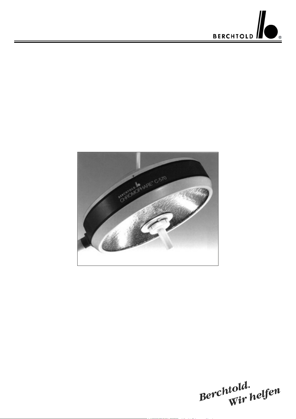
CHROMOPHARE® C 570
CHROMOPHARE
Service-Manual (D, E)
®
C 571

Inhaltsverzeichnis
für Service-Manual
C 570/C 571
Themen Seite
Einführung
Technische Daten 5 – 6
4
Schaltungsbeschreibung
Gültig bis Serien Nr. 152.000
Schaltplan
Gültig bis ca. Serien Nr. 152.000
Schaltungsbeschreibung der Regelungsplatine
Gültig ab Serien Nr. 152.000 13
Stromlaufplan
Gültig ab Serien Nr. 152.000 14
Ersatzteilliste 15 – 20
Bildliche Ersatzteildarstellung 21 – 37
Gültig bis Serien Nr. 152.000
Gültig ab Serien Nr. 152.000
Gültig für alle Ausführungen
LFN
EndoLite®
CFWP
Stativ (SO)
Wand (W)
Meßpunkte – Halogenlampenspannung 37
Vergleichstabelle für max. Halogenlampenspannung
Gültig ab Serien Nr. 152.000 38
9 – 11
12
21
22
23 – 29
29 – 30
31
32 – 34
35
36 -37
Meßpunkte - Fehlersuche 39 - 43
Einstellen des Gewichtsausgleichs am Federarm 44 - 45
Einstellung des Höhenanschlags am Federarm 45
Anschlußplan für C 570/C 571 Transformatoren und Notstromrelais am Deckenrohr montiert
Anschlußplan für C 570/C 571 Transformatoren und Notstromumschaltrelais separat im bauseitigem Wandschaltkasten 47
Sicherungen 48
46
2
CHROMOPHARE®C 570/C 571 Service Manual (D, E)

Table of contents
for Service-Manual
C 570/C 571
Contens Page
Introduction 4
Technical Data 7 – 8
Functional Description
valid up to Serial no. 152.000 9 – 11
Connecting Diagram
valid up to. Serial no. 152.000 12
Functional Description of light intensity regulation board
valid from serial no. 152.000 13
Wiring Diagram
valid from serial no. 152.000 14
Spare Part List 15 – 20
Graphic spare part description 21 – 37
Valid up to serial no. 152.000
Valid from serial no. 152.000
Valid for all types
LFN
EndoLite®
CFWP
Mobile (SO)
Wall mounted (W)
Testpoints – halogen bulb supply voltage 37
Compare Table for max. halogen bulb supply voltage
valid from Serial no. 152.000 38
21
22
23 – 29
29 – 30
31
32 – 34
35
36 - 37
Measuring Points – trouble shooting 39 - 43
Adjustment of the weight compensation on the Acrobat Arm 44 - 45
Adjustment of the height movement on the Acrobat Arm 45
Electrical Diagram of C 570/C 571 Transformers and emergency
relays mounted on the ceiling tube 46
Electrical Diagram for C 570/C 571 Transformers and emergency
relais mounted in a wall box on side of building 47
Fuses 48
CHROMOPHARE®C 570/C 571 Service Manual (D, E)
3

Einführung
Introduction
Die BERCHTOLD CHROMOPHARE®
ist eine moderne Operationsleuchte mit
wesentlichen technischen Neuerungen.
Durch Anwendung moderner Elektronik,
einen computerberechneten Polygonreflektor, eine leichtgängige Kreisfahrbahn mit kardanischer Aufhängung des
Leuchtenkörpers werden viele Vorteile geboten:
• hohe Schattenfreiheit im Operationsfeld
• hohe Beleuchtungsstärke bei tageslichtähnlicher Farbtemperatur
• sichere Hygiene durch glatte Außenflächen ohne vorstehende Bedienungselemente und luftdichten Abschluß des
Leuchtenkörpers
• großer Bereich der Höhenverstellung
• Die Auswechslung von defekten Halogenlampen ist leicht zu bewerkstelligen
und kann vom Pflegepersonal selbst vorgenommen werden
• Der mechanische Aufbau und die Funktion der elektronischen Schaltkreise werden
auf den folgenden Seiten detailliert beschrieben.
• Für die Bedienung, die Montage und
Elektro-Installation werden der Leuchte bei
Auslieferung eine ausführliche Bedienungsanleitung und eine gesonderte Montageanleitung beigefügt.
The BERCHTOLD CHROMOPHARE® is
the latest in the new generation of surgical
lights, and features many new technological
advances.
Many advantages are offered by utilizing the
latest electronic technics, a computer designed polygon-reflector, and cardanic suspension of the light head.
They include:
• Freedom from shadows in the operating
field
• High luminous power which generates the
high illumination and high colour temperature similar to daylight
• Easier hygiene due to smooth styling of the
light body - the absence of control knobs on
the outer surface, and airtight sealing of the
light head
• Larger range of height adjustment; greater
mobility of the light
• Easy replacement of defective halogen
bulbs by OP staff
•The construction of mechanics and control
functions will be described in detail on the
following pages.
•Diagrams and electrical specs accompany
the descriptions. An installation and mounting instruction manuals are included to aid in
the mounting and electrical installation.
• Modern braking system; the suspension arm
can be moved inward in the direction of the
operating site, from the outmost dead center
position, and overcomes the dead point
4
CHROMOPHARE®C 570/C 571 Service Manual (D, E)
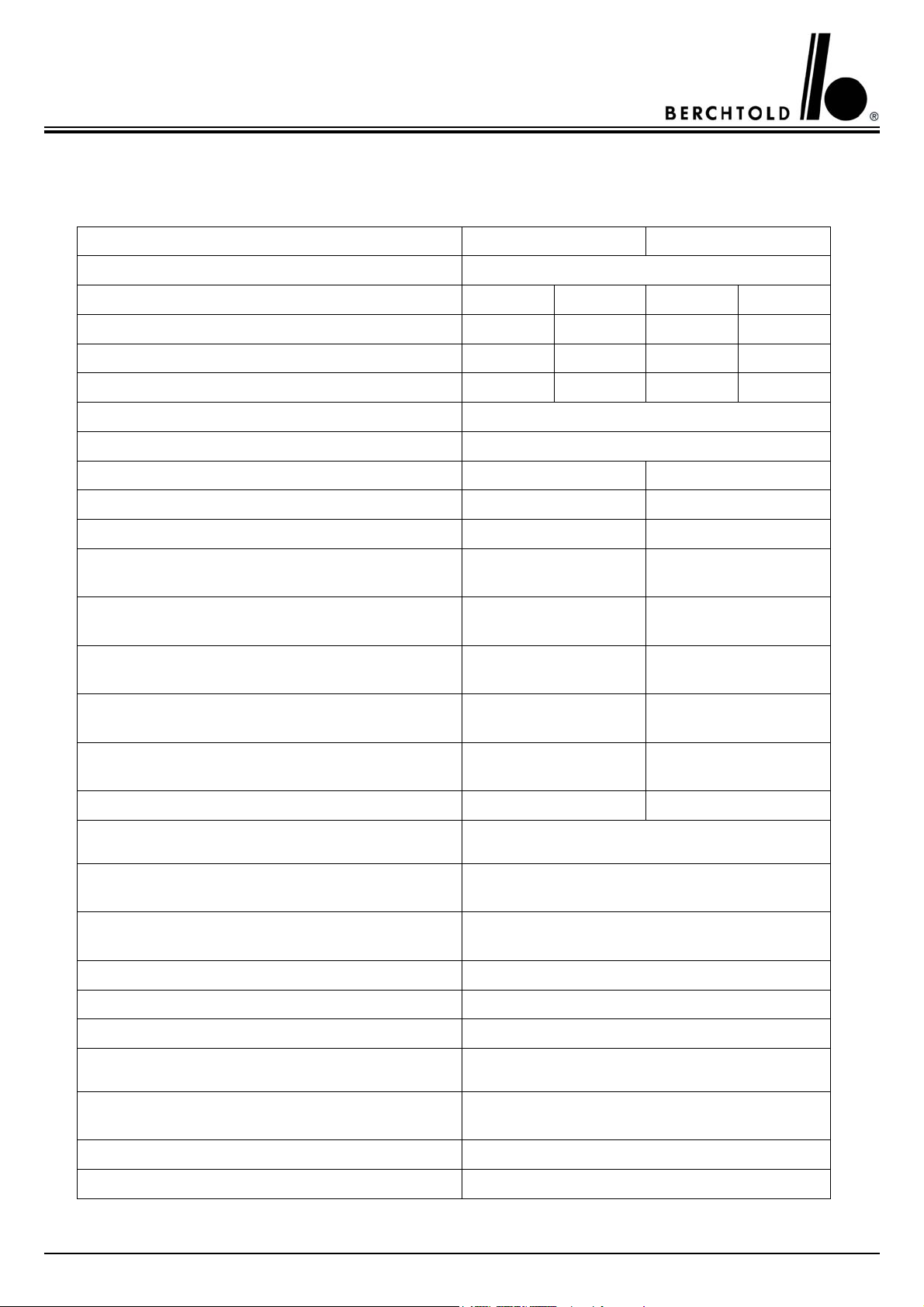
Technische Daten BERCHTOLD CHROMOPHARE® Operationsleuchte C 570/C 571
Lichttechnische Daten C 570 C 571
Reflektorsystem Polygonreflektor
Farbtemperatur 4500 K 3600 K 4500 K 3600 K
Beleuchtungsst. Ec in 1 m Abstand [klx] 75 90 100 120
Helligkeitsregulierung (elektronisch) [klx] 45 - 75 55 - 90 45 - 100 55 - 120
Gesamtbestrahlungsstärke bei max. Intensität 280 W/m2335 W/m2370 W/m2 447 W/m
2
Bestrahlungsst./Beleuchtungsst. [mW/m2lux 3,7
Farbwidergabeindex Ra 94
Feldverstellung 20 - 28 cm 18 – 28 cm
Lichtfeld Ø bei 10% der max. Beleuchtungsstärke 20 cm 18 cm
Lichtfeld Ø bei 50% der max. Beleuchtungsstärke 10 cm 9 cm
Restbeleuchtungsstärke bei Abschattung durch
ein Schatter in Bezug auf Ec
Restbeleuchtungsstärke bei Abschattung durch
zwei Schatter in Bezug auf Ec
Restbeleuchtungsstärke in normiertem Tubus in
Bezug auf Ec
Restbeleuchtungsstärke in normiertem Tubus mit
einem Schatter Bezug auf Ec
Restbeleuchtungsstärke in normiertem Tubus mit
zwei Schattern Bezug auf Ec
26 %
45 %
100 %
26 %
45 %
26 %
45 %
100 %
24 %
45 %
Ausleuchtungstiefe L1 + L2 130 cm 130 cm
Elektrische Anschlußdaten
Prim. Wechselspannung des Trafo 110 / 120 / 130 V A.C.
220 / 230 / 240 V A.C.
Leistungsaufnahme 250 VA
oder 190 VA bei 28 V D.C.
Nennleistung Trafo / Frequenz 250 VA / 50/60 Hz
Schutzklasse 1
Schutzart IP 53
Allgemeine Daten
Halogenlampe
Bestell-Nummer
24 V / 150 W
CZ 908-24
Lebensdauer der Halogenlampen 1000 h
Automatische Umschaltung auf Reservelicht ja
CHROMOPHARE®C 570/C 571 Service Manual (D, E)
5

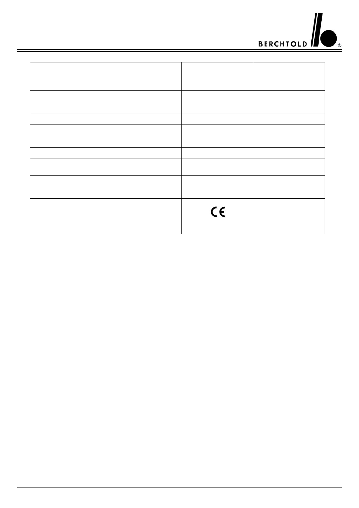
Abmessungen
Durchmesser des Leuchtenkörpers 57 cm
Durchmesser des Polygonreflektors 50 cm
Lichtaustrittsfläche 2092 cm2
Max. Schwenkradius 226 cm
Tiefstellung des Leuchtenkörpers 128 cm
Höchststellung des Leuchtenkörpers 224 cm
Freie Durchgangshöhe 200 cm bei 265 cm Raumhöhe
Gewicht / Drehmoment
Gewicht incl. Trafo 61 kg
Max. Drehmoment 278 Nm
Zertifikate
konform mit 93/42/EWG
UL listed
6
CHROMOPHARE®C 570/C 571 Service Manual (D, E)

Technical Data BERCHTOLD CHROMOPHARE® Surgical Lights C 570/C 571
Light technical data C 570 C 571
Reflector system Polygonreflector
Colour temperature 4500 K 3600 K 4500 K 3600 K
Intensity Ec at 1 m [klx] 75 90 100 120
Intensity control [klx] 45 - 75 55 – 90 45 - 100 55 - 120
Total radiant power at max intensity 280 W/m2335 W/m2370 W/m2 447 W/m
Total radiant power/intensity Ec [mW/m2lux] 3,7
Colour rendering index Ra 94
Light field diameter 20 - 28 cm 17 - 28 cm
2
d
d
Remaining illuminance when beam is obstructed by
Remaining illuminance when beam is obstructed by
Remaining illuminance inside at the bottom of a
Remaining illuminance inside at the bottom of a
Remaining illuminance inside at the bottom of a
Light field dia. at 10% of max intensity 20 cm 17 cm
10
Light field dia. at 50% of max intensity 10 cm 8,5 cm
50
one mask
26 %
two mask
45 %
standardised tube.
100 %
standardised tube. Beam obstructed by one mask
26 %
standardised tube. Beam obstructed by two mask
45 %
24 %
45 %
100 %
24 %
45 %
Depht of illumination L1 + L2 130 cm 130 cm
Electrical data
Primary voltage of transformer
110 / 120 / 130 V A.C.
220 / 230 / 240 V A.C.
Power consumption
250 VA
or 190 VA at 28 V D.C.
Rated capacity of transformer / frequency 250 VA / 50/60 Hz
Safety Category 1
Protection provided by enclosure IP 53
General data
Halogen bulb
Order no.
24 V / 150 W
CZ 908-24
Life time of halogen bulb 1000 h
Automatic switch over to reserve bulb yes
CHROMOPHARE®C 570/C 571 Service Manual (D, E)
7
W
Dimensions C 570 C 571
Diameter of light body 57 cm
Diameter of Polygon Reflectors 50 cm
Light emission surface (glass surface) 2092 cm2
Max. swivel radius 226 cm
Lowest position of light body 128 cm
Highest position of light body 224 cm
Clearance (single light) 200 cm at 265 cm finished ceiling
Weight / Torque
Max. torque 278 Nm
Certificate
eight with. transformer 61 kg
conform with 93/42/ EEC
UL listed
8
CHROMOPHARE®C 570/C 571 Service Manual (D, E)

Schaltungsbeschreibung der
BERCHTOLD CHROMOPHARE®
Operationsleuchte C 570/C 571
Gültig bis Serien Nr. 152.000
Functional Description of the
BERCHTOLD CHROMOPHARE®
C 570 / C 571 Operating Light valid
up to serial no. 152.000
Transformator und NotstromUmschaltung
Die Netzspannung wird über einen
Hauptschalter und die Sicherungen F
12 und F 13 an den Transformator T
1 geschaltet. Es liegt dann aus der
Sekundärwicklung des Transformators
eine Spannung an Relais K 9. Dieser
Stromkreis wird mit der Sicherung F
11 abgesichert. Relais K 1 zieht an
und schaltet mit seinen Kontakten die
Transformator-SekundärBetriebsspannung an die Operationsleuchte. Bei Netzausfall gehen die Relaiskontakte von Relais K 9 in Ruhestellung und schalten die Leuchte an
die Notstrom-Versorgung. Dieser
Stromkreis wird durch die Sicherungen F 14 und F 15 abgesichert.
Ein-Aus-Schaltung der Leuchte
Platine 1
Die über die Steckerkontakte X 1 und
X 2 zugeleitete Betriebs-Wechselspannung wird mit Brückengleichrichter V
1 gleichgerichtet und mit Kondensator C 1 geglättet. Mit dieser Spannung
wird das bistabile Relais K 1 versorgt.
Wird mit Tastenschalter S 1 (EinTaste) Spannung an die Spule I des
Relais K 1 gelegt, schließt sich Relaiskontakt K 1 und es fließt Strom durch
die Halogenlampe H 1. Die Leuchte
ist eingeschaltet. Der Restmagnetismus im Relais K 1 hält den Relaiskontakt K 1 geschlos-sen. Wird mit Tastenschalter S 2 (Aus-Taste) Spannung
an die Spule II des Relais K 1 gelegt,
wird der Restmagne-tismus aufgehoben, der Relaiskontakt K 1 geht in
seine Ruhestellung zurück, der Stromkreis für die Halogenlampe wird unterbrochen, die Leuchte ist abgeschaltet. Der Stromkreis für Relais K 1 ist
mit Sicherung F 1 abgesichert.
Einstellung der Beleuchtungsstärke
Platine 1
Bei eingeschalteter Leuchte wird die
Betriebs-Wechselspannung mit Brückengleichrichter V 4 gleichgerichtet,
mit Kondensator C 2 geglättet und
mit Spannungsregler IC 2 auf 12 Volt
geregelt und stabilisiert
Transformers and Emergency Power Switch Over
The current is sent from a mains
switch and the fuses F 12 and F 13, to
the T 1 transformer. A secondary
cable runs the current from the transformer to the K 9 relay. This circuit is
secured by the F 11 fuse. Relay K 1 is
activated and in turn switches on the
contacts of the transformer’s secondary circuit, which switches on the
light. Should the power supply fail,
relay K 9 switches into the offposition connecting the light to the
emergency power supply. This circuit
is secured by the fuses F 14 and F 15.
ON - OFF Switching of the light
Circuit Board 1
The A 7 voltage supplied from the
contacts X 1 and X 2 is rectified by
the bridge connected rectifier V 1 and
flattened by capacitor C 1. This voltage operates the bistable relay K 1. If
the push button switch S 1 (on key)
allows voltage to read coil I of the
relay K 1, relay contact k 1 closes, and
current flows through the halogen
bulb H 1, the light is switched on. The
residual magnetism in relay K 1 holds
relay contact k 1 closed. If push button switch S 2 (off key) allows voltage
to flow to coil II of relay K 1, the
residual magnetism disappears and
relay contact k 1 returns into its rest
position, the circuit to the halogen
bulb is cut, and the light is switched
off. The electrical current for relay K
1 is protected by the F 1 fuse.
Regulating the Light Intensity
Circuit Board 1
If the light is switched on, the A.C.
working voltage is rectified by bridge
connected rectifier V 4 and flattened
by capacitor C 2 and adjusted to 12
Volt by voltage control IC 2 and stabilized.
CHROMOPHARE®C 570/C 571 Service Manual (D, E)
9

Die Kondensatoren C 7 und C 8 ver-
hindern Störeinflüsse auf den Spannungsregler IC 2. Diese Spannung
wird über die Tastenschalter S 3 (geringere Beleuchtungsstärke) oder S 4
(höhere Beleuchtungsstärke) an den
Antriebsmotor M 1 geschaltet. S 3
und S 4 schalten jeweils unterschiedliche Polarität an den Antriebsmotor M
1 und bestimmen dessen Drehrichtung. Mit Motor M 1 wird das Regelpotentiometer R 8 für die Betriebsspannung der Halogenlampe angetrieben, und somit die Beleuchtungsstärke der Operationsleuchte
geregelt. Der Stromkreis für den
Stellmotor M 1 ist mit der Sicherung
F 2 abgesichert.
Einschaltung der Reservelampe
H 2
Platinen 1 und 10
Die mit Brückengleichrichter V 4 und
Kondensator C 2 gleichgerichtete
Betriebsspannung wird mit Spannungsregler IC 1 auf 24 Volt geregelt
und stabilisiert. Die Kondensatoren C
3 und C 4 verhindern Störeinflüsse
auf den Spannungsregler IC 1. Bei
eingeschalteter Leuchte wird Transistor V 8 über Kondensator C 6 und
Widerstand R 6 angesteuert und
schaltet Widerstand R 4 an Minus.
Dadurch sperrt Transistor V 9 die
Versorgungsspannung von Relais K
2. Der Relaiskontakt K 2 bleibt geöffnet, die Reservelampe H 2 erhält
keine Spannung. Über Widerstand R
3 wird Kondensator C 5 aufgeladen.
Solange die Halogenlampe H 1 leuchtet, bleibt der Phototransistor V 30
auf Platine 10 niederohmig und verhindert das Ansteigen der Spannung
an Kondensator C 5. Transistor V 7
bleibt gesperrt und Transistor V 8
bleibt leitend, Transistor V 9 bleibt
gesperrt. Bei einem Defekt der Halogenlampe H 1 wird der Phototransistor V 30 auf Platine 10 hochohmig
und an Kondensator C 5 steigt die
Spannung. Dadurch schaltet der
Transistor V 7 die Basis von Transistor V 8 an Minus. V 8 sperrt, Transistor V 9 erhält über
The capacitors C 7 and C 8 avoid disturbing effects to read voltage control
IC 2. The circuit is switched over the
the M 1 driving motor by the control
switch S 3 (lower light intensity), or by
control switch S 4 (higher light intensity). Then, S 3 and S 4 switch on different polarities on the M 1 driving
motor, and determine ist turning direction. Motor M 1 in turn drives the
potentiometer R 8 to regulate the current of the halogen bulb. This is how
the light intensity is regulated, by activating the M 1 motor. Electrical current to M 1 motor is protected by the
F 2 fuse.
Switching on the H2 Reserve Bulb
Circuit Boards 1 and 10
The working voltage rectified by
bridge connected rectifier V 4 and
capacitor C 2 is regulated to 24 Volts
by voltage control IC 1 and stabilized.
The capacitors C 3 and C 4 avoid disturbing effects to read voltage control
IC 1. When the light is turned on,
transistor V 8, regulated by capacitor C
6 and resistor R 6, turns resistor R 4 to
minus. In this way, transistor V 9 cuts
the voltage supply of relay K 2. Relay
contact K 2 stays open, reserve lamp
H 2 receives no voltage. Capacitor C 5
is charged by resistor R 3. As long as
halogen bulb H 1 lights, the phototransistor V 30 on circuit board 10 is
kept at a low impedance, and prevents
the voltage increase on capacitor C 5.
Transistor V 7 remains insulating and
transistor V 8 remains conductive,
transistor V 9 remains insulating. If
halogen bulb H 1 becomes dark because of a defect, phototransistor V 30
on board 10 switches to a high ohm
output, and voltage increases on capacitor C 5. By this transistor V 7
switches the base of transistor V 8 to
minus. V 8 insulates, transistor V 9
obtains a single wire resistor R 5 and
switches to minus. The relay K 2 is
activated, the relay contact K2 closes,
and current for stand-by lamp H 2 can
flow.
10
CHROMOPHARE®C 570/C 571 Service Manual (D, E)

Widerstand R 5 ein Signal und schaltet
auf Minus. Das Relais K 2 erhält nun
Spannung, der Relaiskontakt K 2
schließt sich und es kann Strom für die
Reservelampe H 2 fließen. Parallel zu
Relais K 2 wird über Widerstand R 7 die
Leuchtanzeige V 12/V 14 (aus Platine 2)
an Minus geschaltet, leuchtet und signalisiert „Lampe defekt“. Diese Anzeige
leuchtet so lange, bis die defekte Halogenlampe H 1 gegen eine neue ausgewechselt ist.
Parallel to relay K 2, the illuminated read
out V 12/V 13 (on board 2) is switched
to minus via resistor R 7 and so lights up
to signal „bulb defective“. This warning
lights as long as the defective halogen
bulb H 1 is exchanged for a new one.
CHROMOPHARE®C 570/C 571 Service Manual (D, E)
11
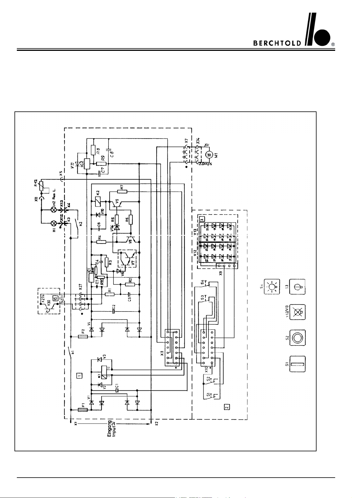
Schaltplan C 570 bis Serien Nr. 152.000
C 571 bis Serien Nr. 152.000
Connecting Diagram C-570 valid up to serial no. 152.000
C-571 valid up to serial no. 152.000
12
CHROMOPHARE®C 570/C 571 Service Manual (D, E)

Schaltungsbeschreibung der Regelplatine C 570/C 571
Gültig ab Serien Nr. 152.000
Functional Description Light intansity control board
C 570 / C 571 valid from serial
no. 152.000
Die Betriebsspannung (Klemmenspannung) von A.C. – 25,5 V – oder D.C. –
27,5 V (gemessen an der Deckenklemme unter max. Last) wird über die
orange und graue Leitung (AWG 16,
Litze) an Stecker X2 auf der Regelungsplatine im OP-Leuchten-körper an Pin 5
(orange) und 6 (grau) angeschlossen.
Über den Gleichrichter V5 und Kondensator C8 wird das Einschaltrelais K1
(bistabil) an Spannung gelegt. Wird S1
(Ein) betätigt, zieht Relais K1 an und
hält sich selbst. Wird S2 (Aus)betätigt, so
fällt Relais K1 wieder ab. Über K1 wird
die Betriebsspannung (einpolig) auf den
Leistungsgleichrichter V1 gelegt. V1
richtet die Betriebsspannung gleich.
The input voltage of 25,5 V AC – or
27,5 V DC (measured at the screw joint
on top of the ceiling tube with max. load
) is connected via the orange and grey
cables to the connector X 2 at pin 5
(orange) and pin 6 (grey) to the OR-light
head. The relay K 1 (bistable) is supplied
from the rectifier V 5 and the capacitor
C 8 if switch S 1 (on) will be closed. If
the contact of S 1 will be closed the relay
K1 will come and will stay in hold position. If the contact of S 2 will be closed
the relay will cut off. The contact of
relay K 1 will switch the input voltage to
the power rectifier V1. The rectifier V 1
rectifies the input voltage for the electronic.
CHROMOPHARE®C 570/C 571 Service Manual (D, E)
13
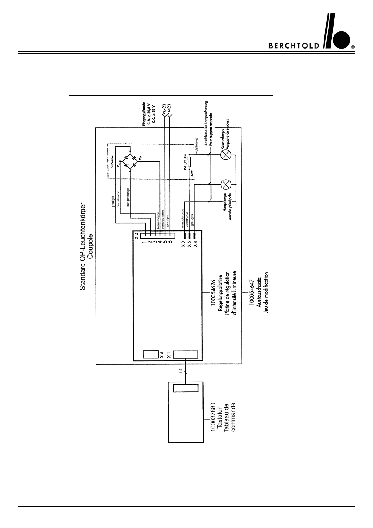
Stromlaufplan der C 570/C 571 gültig ab Serien Nr. 152.000
Wiring Diagram of C 570 / C 571 valid from serial no. 152.000
14
CHROMOPHARE®C 570/C 571 Service Manual (D, E)

Ersatzteilliste
Spare Part List
Beschreibung
description
Gültig bis Serien Nr. 152.000
Valid up serial no. 152.000
Steuerplatine
control board
Lichtreglergruppe, komplett
light intensity regulator group, cpl.
Photo-Transistor
photo transistor
Gültig ab Serien Nr. 152.000
Valid from serial no. 152.000
Lichtregelungsplatine
light intensity regulation board
Widerstand auf Winkel
resistor on fixation
Teile Nr.
part no.
42775 21
49695 21
37882 21
22
54626
54614 22
Abbildung auf Seite
description on page
Gleichrichter
Rectifier
Gültig für alle Ausführungen
Valid for all types
Tastaturplatine
key board
Mikroschalter
micro switch
Tastaturfolie
key board foil
Fassungshalter
socket holder
Kabelverbinder
cable connector
Bremsschraube
friction screw
Bremsschraube
friction screw
47971 22
23
37880
37801 23
37837 23
59880 23
39903 23
38821 23
38827 23
Bremsschraube
friction screw
64103 23
CHROMOPHARE®C 570/C 571 Service Manual (D, E)
15
 Loading...