

Bently Nevada Ranger Pro 70M303, Ranger Pro 70M300, Ranger Pro 70M301, Ranger Pro User Manual
Page 1
Ranger Pro Wireless Condition Monitoring
User Guide
Bently Nevada Machinery Condition Monitoring
Document: 125M6113
Rev. C
Page 2

Ranger Pro Wireless Condition Monitoring
User Guide
Copyright 2019 Baker Hughes, a GE company, LLC ("BHGE")
All rights reserved.
Bently Nevada, Orbit Logo and Ranger are registered trademarks of BHGE in the United States and
other countries. All product and company names are trademarks of their respective holders. Use
of the trademark does not imply any affiliation with or endorsement by the respective holders.
The information contained in this document is the property of BHGEand its affiliates; and is
subject to change without prior notice. It is being supplied as a service to our customers and may
not be altered or its content repackaged without the express written consent of BHGE.
This product or associated products may be covered by one or more patents. See
Bently.com/legal.
Contact Information
Mailing Address 1631 Bently Parkway South
Minden, Nevada USA 89423
Telephone 1.775.782.3611
1.800.227.5514 (US only)
Internet Bently.com
2/51 125M6113 Rev. C
Page 3

Ranger Pro Wireless Condition Monitoring
User Guide
Contents
1. General Safety 4
1.1 Receiving Inspection 4
1.2 Handling and Storing Considerations 4
1.3 Personal Safety Warnings 5
1.4 Safe Disposal 8
2. Hardware 9
2.1 Intended Use 9
2.2 Compliance Information 9
2.3 Description 9
2.4 System Components Required 10
3. Network Design 13
3.1 Consider Sensor Range 13
3.2 Consider Battery Life 13
3.3 Choose Network Topology 14
3.4 Plan Device Placement 15
4. Installation and Configuration 17
4.1 Install Battery 17
4.2 Configure Devices 20
4.3 Provision Devices 24
4.4 Unprovision Sensors 26
4.5 Reboot the Device 28
4.6 Mount Devices 28
5. Verification 33
5.1 Verify Network Connectivity 33
5.2 Validate Device Data 34
6. Maintenance 37
6.1 Monitor Battery Levels 37
6.2 Clean and Inspect Devices 38
6.3 Reboot the Sensor 42
6.4 Update Device Firmware 43
6.5 Update Radio Firmware 50
6.6 Harden the System 51
3/51 125M6113 Rev. C
Page 4

Ranger Pro Wireless Condition Monitoring
User Guide
1. General Safety
1.1 Receiving Inspection
Visually inspect the monitor for obvious shipping damage. If you detect shipping damage, file a
claim with the carrier and submit a copy to Bently Nevada. Include all model numbers and serial
numbers with the claim.
1.2 Handling and Storing Considerations
Proper handling of components, best practices for system installation, and diligent inspection
procedures for the system will prolong the service life of the system. Additionally, procedures for
dealing with system components replaced by maintenance are detailed to allow compliance with
regulations relating to electronic waste.
Devices
The Ranger Pro Wireless Condition Monitoring is shipped in a foam-filled package, and may be
shipped with test data. DONOTDISCARDTHISTESTDATA!
4/51 125M6113 Rev. C
Page 5
Ranger Pro Wireless Condition Monitoring
User Guide
1.3 Personal Safety Warnings
Labels and markings are provided on the monitor to guide the system integrator in the processes
of choosing appropriate interface equipment, determining safe use conditions, and identifying
recommended installation procedures. The format of these markings are governed by the
standards that dictate safe use and environmental compliance in a variety of regions and
regulated settings.
Potential Electrostatic Charging Hazard
WARNING
ELECTROSTATIC CHARGING HAZARD
RISK OF PERSONAL INJURY OR EQUIPMENT DAMAGE.
Potential for electrostatic charging hazard.
Do not separate when energized.
Remove power before service.
Connect grounding before power.
Installations and maintenance tasks performed in potentially hazardous areas must be performed
only after the area has been verified to be free of hazardous materials, atmospheres, and
conditions.
l Do not discharge static electricity onto the circuit board. Avoid tools or procedures that
would subject the circuit board to static damage. Some possible causes of static damage
include ungrounded soldering irons, nonconductive plastics, and similar materials.
l
Use a suitable grounding strap before handling or performing maintenance on a printed
circuit board.
l
Transport and store circuit boards in electrically conductive bags or foil.
l
Use extra caution during dry weather. Relative humidity less than 30% tends to multiply the
accumulation of static charges on any surface.
The following situations could cause a spark enough to ignite an explosion:
l Potential of electrostatic discharge on plastic components, or
l Removal or placement of an energized connection.
5/51 125M6113 Rev. C
Page 6
Ranger Pro Wireless Condition Monitoring
User Guide
Hazardous Environment
WARNING
HAZARDOUS ENVIRONMENT
Risk of explosive atmosphere.
De-energize all relays and connections before placement or removal.
Take precautionary measures to avoid electrostatic potential,
especially on plastic components.
Installations and maintenance tasks performed in potentially hazardous areas must be performed
only after the area has been verified to be free of hazardous materials, atmospheres, and
conditions.
The following situations could cause a spark enough to ignite an explosion:
l Potential of electrostatic discharge on plastic components, or
l Removal or placement of an energized connection.
6/51 125M6113 Rev. C
Page 7
Ranger Pro Wireless Condition Monitoring
User Guide
Lithium Batteries
WARNING
USE ONLY ONE OF THE FOLLOWING
BATTERIES
Xeno Energy XL-205F, Tadiran TL-5930, Tadiran SL-2780. Don’t use a
device with a damaged e-module, O-rings, sensor module, or battery.
Using a damaged battery may further damage the device, cause it to
fail, or in hazardous locations cause other unintended consequences.
The Ranger Pro wireless sensor uses 3.6V lithium-thionyl chloride D-cell batteries. Lithium
batteries are volatile.When handling and storing lithium metal batteries, follow these precautions:
l Store and handle lithium metal batteries to avoid contact with other lithium batteries.
l Don't place lithium metal batteries on metal work surfaces.
l Avoid exposing lithium metal batteries to extreme temperatures.
l If you store an inactive Ranger Pro sensor, remove the battery.
l Dispose of depleted or defective batteries in keeping with applicable statutes and
regulations as well as site-specific safety requirements.
The lithium batteries will typically last up to five years. Use the Ranger Pro software or your
network vendor's application to monitor battery performance and replace batteries as needed.
7/51 125M6113 Rev. C
Page 8

Ranger Pro Wireless Condition Monitoring
User Guide
1.4 Safe Disposal
Replacing Device and Failure Analysis
Visit Bently.com to initiate the process for returning parts under warranty and request failure
analysis.
Hazardous Materials
This device does not use hazardous materials outlined by RoHS or battery directive statutes.
These regulations confirm that lead, mercury, cadmium, hexavalent chromium, polybrominated
biphenyls, polybrominated diphenyl ether, and battery related materials such as lithium are
limited to no more than trace amounts within the system.
Recycling Facilities
Decommissioning of instrumentation should endeavor to minimize the impact of the waste
created by disposal of system material. Refer to local or regional waste removal administration to
collect information on proper material collection, reuse, and recycling.
Product Disposal Statement
Customers or third parties who are not member states of the European Union andwho are in
control of the product at the end of its life or at the end of its use, are solely responsible for
diligent product disposal at the end of its useful life. No person, firm, corporation, association, or
agency shall dispose of the product in a way that is in violation of any applicable international,
federal, state, or local regulations. Baker Hughes, a GE company, LLC ("BHGE") is not responsible
for product disposal at the end of its useful life. Visit www.weeerohsinfo.com for recycling
information.
8/51 125M6113 Rev. C
Page 9

Ranger Pro Wireless Condition Monitoring
User Guide
2. Hardware
2.1 Intended Use
Ranger Pro sensors are intended for monitoring purposes only and should not be used in control
or safety systems.
2.2 Compliance Information
FCC ID: XFU-121M64A
IC ID: 8349A-121M64A
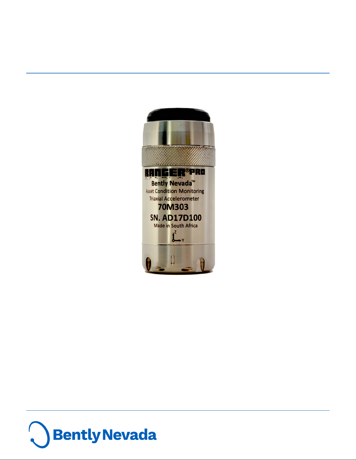
2.3 Description
The Ranger Pro ISA100.11a wireless sensor measures temperature, acceleration, and velocity.
Temperature A sensor embedded in the device base measures contact temperature.
Discrete, piezoelectric sensing elements measure acceleration in the Z
Acceleration Overall
Velocity Overall
There are three versions of the device:
Ranger Pro 70M303
tri-axial sensor
Ranger Pro 70M301
uniaxial sensor
Ranger Pro 70M300
repeater
Both the tri-axial and uniaxial sensors can also act as routers, although using the router mode
depletes the unit’s battery more quickly.
If a Ranger Pro device can’t communicate with an access point, you can use the Ranger Pro router
to extend your network. We recommend connecting no more than three Ranger Pro sensors to a
Ranger Pro router, although you may be able to connect up to eight.
axis for Uni-Axial Ranger Pro Wireless Sensors and in the X, Y and Z
directions for Tri-Axial Ranger Pro Wireless Sensors. Overall
acceleration is calculated over 2.5 seconds.
Calculated from the acceleration waveform and the overall value is
calculated over a 2.5 second duration.
Detects velocity and acceleration in three axis (X,Y,andZ) and
measures surface temperature.
Detects velocity and acceleration in one-axis (vertical,orZ) only and
measures surface temperature.
Enables you to extend the range between sensors and network access
points.
9/51 125M6113 Rev. C
Page 10

Ranger Pro Wireless Condition Monitoring
User Guide
2.4 System Components Required
To install, configure, and use the Ranger Pro Ranger Pro wireless sensor, you need:
l Lithium-thionyl chloride batteries, one per device. For approved battery types, see the
Ranger Pro Datasheet (document 125M5237).
l Battery installation tool.
l Ranger Pro, either or both tri-axial and uniaxial devices, with batteries installed.
l (Optional) Ranger Pro repeaters with batteries installed.
l Mounting hardware (plus adapters, if needed).
l A compatible USB NFC reader, either the Identiv uTrust 3700 F Contactless NFC reader or
the Sony RC-S380/S NFCreader.
l Ranger Pro configuration software (121M7997, available from Bently Nevada technical
support).
l Spot facing tool, if required. (Not provided by Bently Nevada.)
l Torque wrench with ¼ inch drive, capable of tightening devices in the 5-7 Nm
(44to62inlb)range. (Not provided by Bently Nevada.)
10/51 125M6113 Rev. C
Page 11
Ranger Pro Wireless Condition Monitoring
User Guide
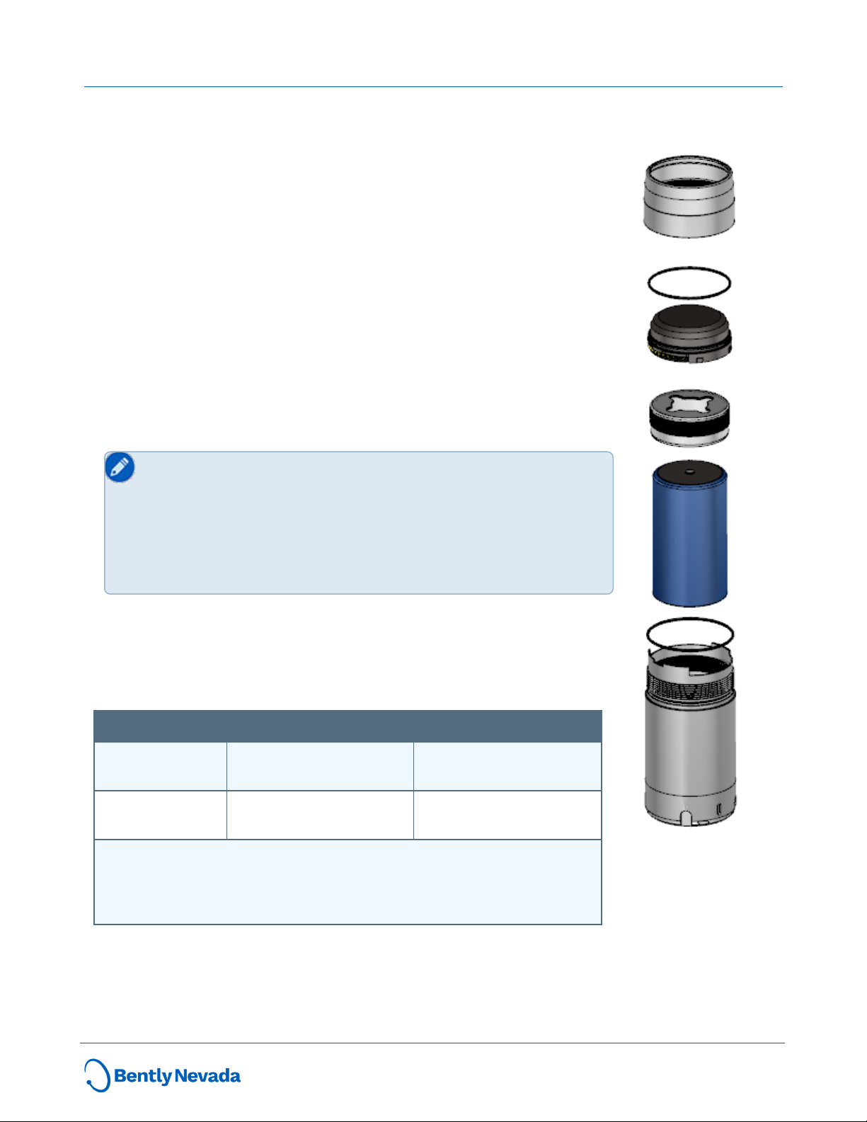
Ranger Pro Components
The Ranger Pro device is composed of six parts:
l Case. Contains the vibration and temperature sensors and forms the
device housing (316 stainless steel body).
l Wireless e-module (glass-reinforced, impact-resistant PPS).
l e-module retaining ring.
l Battery (replaceable D-sized 3.6V lithium-thionyl chloride).
l Battery retaining ring.
l Two O-ring seals (35x1mm on sensor body and 34x1 mm on e-
module).
An Installation Kit (130M5452) is also available. The installation kit can be
ordered with or without the USB NFC reader. For ordering information,
see the Ranger Pro Datasheet (document 125M5237).
Use only approved D-sized lithium-thionyl chloride batteries for
the Ranger Pro sensors and repeaters. If you use the wrong
battery, you can negatively affect device performance, produce
inaccurate readings, and void the Ranger Pro warranty. You can
purchase approved batteries from Bently Nevada or third-party
suppliers. For details and ordering information, see the Ranger
Pro Datasheet (document 125M5237).
Network Requirements
Ranger Pro devices operate on these compatible ISA100.11a wireless
networks and gateways. Additional licenses may be required to activate
these gateways.
Manufacturer Gateway Manager Access Point
Yokogawa YFGW410 (R2.01.04 or
equivalent)
Honeywell‡ WDM (R310.2-4 or later) FDAP (OW 230 or later)
‡ Honeywell OneWireless Wireless Device Manager using firmware
R310.2-4 limits the maximum number of RangerPro wireless devices
to 140 per gateway. To increase the limit to 160 or more devices,
upgrade to a newer version of the firmware when available.
YFGW510 (R1.07.01 or
equivalent)
CISCO 1552S
11/51 125M6113 Rev. C
Page 12

Ranger Pro Wireless Condition Monitoring
User Guide
Setup Overview
The Ranger Pro operates on the ISA100.11a wireless network protocol. To add Ranger Pro sensors
to your network, complete these steps:
1. Survey your installation location.
2. Decide where to install Ranger Pro sensors and identify mounting points.
3. Locate and install access points.
4. Locate and install a device manager.
5. Install batteries in each sensor.
6. Provision Ranger Pro sensors (and repeaters, if needed).
7. Mount sensors.
8. Test and verify your installation.
9. Monitor and maintain your sensors and network.
12/51 125M6113 Rev. C
Page 13

Ranger Pro Wireless Condition Monitoring
User Guide
3. Network Design
Ranger Pro sensors operate on the 2.4 GHz band on ISA100.11a wireless networks. To enhance
security, the sensors use 128-bit AES encrypted packets.
3.1 Consider Sensor Range
A sensor can transmit data up to 150 meters (164 yards) to an access point when unimpeded by
environmental influences. A sensor can optimally transmit data to another sensor up to 100
meters (109 yards) or more, but greater distances may negatively affect performance.
The range of Ranger Pro devices is affected by several factors, including:
l Device location
l Line of sight to gateway devices
l Proximity to gateway devices
l Gateway antenna type
l Orientation of the e-module
l Obstacles, including the density and type of materials nearby.
Generally, the denser the industrial environment, the weaker the signal.
You can mount devices in any orientation necessary to monitor the machine or connect to the
network. However, the radio transmission is strongest above and around the device, and weakest
below it. Generally, if you mount a device horizontally, we recommend aligning it with the X-axis
horizontal and Y-axis vertical.
3.2 Consider Battery Life
Batteries for the Ranger Pro device have a typical life of five years under the following conditions:
l The Ranger Pro is configured as a sensor device (not a router).
l Ambient temperatures under 40°C (104°F).
l Good quality radio frequency communications.
l Measurement interval of 30 minutes.
To maximize Ranger Pro device battery life:
l Minimize the number of hops between devices and access points. Poor quality radio
frequency communications increase packet retransmission and reduce battery life.
l Avoid environments with elevated temperatures. Temperatures above 40°C (104°F) cause
the device to consume more power and the battery to discharge more quickly. Elevated
temperatures can reduce battery life by up to 40%.
13/51 125M6113 Rev. C
Page 14

Ranger Pro Wireless Condition Monitoring
User Guide
l Avoid using Ranger Pro devices as both sensors and repeaters. Using a sensor as a router
can reduce battery life to 18 to 24 months.
l Minimize the number of Ranger Pro devices routed through Ranger Pro Repeaters. Avoid
connecting more than eight devices through a single Ranger Pro Repeater, or more than
five devices through a sensor with router enabled. Since Ranger Pro Repeaters are
continually in listen and transmit mode, their battery life is less.
l Use the lowest reasonable measurement interval to monitor vibration and temperature.
More frequent vibration measurements consume more power. For example, changing the
interval from 30 to 10 minutes reduces battery life by about 30%.
3.3 Choose Network Topology
The two most commonly used ISA100.11a network configurations are star and mesh topologies.
Your existing network infrastructure may determine the number of devices you can connect to
access points or the maximum number of hops permitted. A star topology is recommended,
although you may use a combination of both, depending on your needs. Consult your network
infrastructure documentation for details.
Star Topology
A star topology is the most efficient method for building a network. It is suitable for smaller areas
where all devices can directly communicate with an access point.
Mesh Topology
A mesh topology creates redundant communication paths for devices on the network. Mesh
topologies are suitable for devices that cover a large area. When planning a mesh network, it's
critical to avoid a choke point, where many devices attempt to connect to a single point. Avoid
network topologies that require more than three hops and too many nodes routed through a
single node, creating a choke point.
14/51 125M6113 Rev. C
Page 15
Ranger Pro Wireless Condition Monitoring
User Guide
3.4 Plan Device Placement
Installing and configuring ISA100.11a wireless networks is beyond the scope of this user
guide. For details, refer to your vendor's wireless network documentation.
Obtain or develop an accurately scaled site plan detailing the placement of the machinery you
need to monitor, including architectural details like walls and pillars. Then complete a site survey
and plan.
To develop a survey and plan:
1.
On the accurately scaled site plan, mark the locations where you need to install sensors.
l Mount sensors as close as possible to the machine point being monitored.
l To avoid destructive interference, install devices at least 18 inches apart.
l Whenever possible, avoid obstructions such as machinery or walls that might “hide”
devices from routing devices or access point antennae.
l Allow clearance for mechanical installation and suitable clearance around the top (100
mm or 4 inches).
l If possible, install devices at least two meters (6 ½ feet) above ground level with clear
line of site to at least two other devices.
2. Determine the optimal wireless range for each device. Use the map scale and draw a circle
representing the nominal radio frequency range around the proposed location of each
Ranger Pro sensor. (When connecting to an access point, the range is about 50% greater.)
When the device is placed among: Draw a circle with:
Dense metal structures with no line-of-sight 25 m (82 ft)radius
Sparse metal structures with limited line-of-sight 50 m (164 ft) radius
Unobstructed, clear line-of-sight locations 100 m (328 ft) radius
3. Pinpoint the locations of any existing access points and gateways.
l If you’re installing sensors in extremely congested plant areas or in areas with
insufficient wireless connectivity, consider installing additional ISA100.11a gateways
and access points.
l Add locations where you need to install additional access points and gateways.
l When placing ISA100.11a access points and gateways, consider the location of line
power and suitable connections to the existing plant network.
15/51 125M6113 Rev. C
Page 16

Ranger Pro Wireless Condition Monitoring
User Guide
Place access points in locations where as many sensors as possible can connect directly to
each access point. We recommend that you don't exceed 40 devices per access point.
Where possible, minimize the distance from the access point to the furthest Ranger Pro
device.
4. Plan for multiple connections for each device.
l Multiple communication paths are required to increase network redundancy and
prevent a single path failure that would result in a loss of communication.
l Depending on the circle (short, medium, or long) that applies to the location of each
Ranger Pro sensor, verify that each device is within range of at least two, and
preferably three, access points or Ranger Pro repeaters.
l Avoid connecting more than five devices through a single Ranger Pro sensor, or more
than eight devices through a single Ranger Pro Repeater.
5. To extend the range of the wireless network or to reach devices beyond the range of an
access point, consider adding Ranger Pro repeaters. Repeaters ought to be positioned:
l Relatively high above the sensors, preferably at least two meters (6 ½ feet) above
grade. Higher placement dramatically increases signal strength.
l To improve radio frequency transmission, we recommend you install the repeaters
upside down and at least 33 cm (1 ft) from walls and pillars.
l Within a clear line of sight to two other repeaters or access points.
6. Plan for a maximum of four hops between each Ranger Pro device and an access point,
although we recommend a maximum of three hops.
7. If your installation is complex or likely to require additional access points, consider
temporarily installing your network access points and Ranger Pro devices to test your plan.
Use temporary magnetic mounting adapters to test device placement.
To obtain optimal results, carefully plan your network. For complete information, see your
network infrastructure documentation.
16/51 125M6113 Rev. C
Page 17

Ranger Pro Wireless Condition Monitoring
User Guide
4. Installation and Configuration
4.1 Install Battery
We recommend that you install batteries in Ranger Pro devices in an indoors equipment room or
a similar environment. Do not replace batteries in a hazardous area. Use only approved battery
types described in the Ranger Pro Datasheet (document 125M5237) available from
www.bently.com.
To maintain the device’s IP67 dust and water-resistant rating, assemble the device
carefully.
To install a battery in a Ranger Pro device:
1. Turn the e-module retaining ring counter-clockwise and
stop when resistance decreases. Place the device on a flat
surface. Use your index finger and apply firm pressure to the
top of the e-module. Use your other hand and continue to
unscrew and remove the retaining ring.
2. Hold the device and e-module as shown. Use your thumb to
press against the e-module just above the metallic tab on
the case. Apply a slight radial force and push upward until
the e-module is separated from the case.
17/51 125M6113 Rev. C
Page 18

Ranger Pro Wireless Condition Monitoring
User Guide
3. Use the battery installation tool to remove the battery
retaining ring. Turn the ring counter-clockwise. Use the
magnet in the tool to lift the ring from the device case.
4. Inspect the O-rings on the e-module and case to verify they
are present, clean, and undamaged. Apply a very light
coating of silicon-based O-ring grease to the O-rings.
(When replacing the battery, always replace the O-rings.)
5. Inspect the interior threads of the e-module retaining ring to be sure they aren’t damaged.
6. Verify that the positive end of the battery is up and then insert the battery.
Use only approved D-sized lithium-thionyl chloride batteries for the Ranger Pro
sensors and repeaters. For details and ordering information, see the Ranger Pro
Datasheet (document 125M5237).
18/51 125M6113 Rev. C
Page 19

Ranger Pro Wireless Condition Monitoring
User Guide
7. Use the magnetic Ranger Pro battery installation tool to
tighten the battery retaining ring. Hand-tighten the ring
until it contacts the battery, then torque to 5 N-m (44 in-lb).
8. To avoid damaging the e-module, you must first align the
contact pins of the e-module with the contact points in the
case. Angle the e-module and align the contact pins and
back keyway.
9. Now rotate the e-module downward to align the notch on
the other side of the e-module with the notch in the case
and press firmly. You can feel or hear a click when it is in
place. If necessary, hold the sensor in place with your finger.
19/51 125M6113 Rev. C
Page 20

Ranger Pro Wireless Condition Monitoring
User Guide
10. Align the e-module retaining ring over the e-module. If
needed, hold the sensor in place with your finger.
11. To maintain the device’s IP67 rating, be careful to avoid damaging the O-rings. Turn the e-
module retaining ring clockwise two to three turns, and then counter-clockwise about ¼
turn, and repeat until the ring is hand-tight.
12. Verify that the device is tightly sealed. There shouldn't be
any gap between the e-module retaining ring and the case,
as shown below.
4.2 Configure Devices
Ranger Pro devices detect single or tri-axial acceleration using a piezoelectric ceramic sensing
element in the sensor base. The sensor derives velocity from the acceleration signal. The Ranger
Pro devices measure surface contact temperature using a sensor in the device base. The sensor
reports a single temperature per device. You can choose what units are used to measure the data.
Use the configuration software to configure sensor data. You can save configuration settings as a
file to your hard drive, share the settings file locally and remotely, and apply the saved settings to
multiple sensors over the network.
Configuration files include:
l Configuration version
l Identification information
l Acquisition timing and scheduling settings
20/51 125M6113 Rev. C
Page 21

Ranger Pro Wireless Condition Monitoring
User Guide
l Temperature measurement settings
l Vibration measurement settings
You can configure Ranger Pro devices two ways:
ISA Manager Mode
(Over the air
Configuration)
NFC Manager
Mode (Using NFC
reader)
Configure one or many sensors over the network using Ranger Pro
Configuration Software and ISA device manager to configure Ranger Pro
devices wirelessly
Configure Ranger Pro devices one at a time at your desk or in a safe area.
Configuration Modes
You can use the Ranger Pro configuration software to define sensors settings using two modes:
Live View
Preset View
View, modify and update sensor configurations in real-time. Most often
used to change device configuration on a single device.
View, modify, save, and apply saved settings to multiple sensors over the
network. Most often used with customer defined configuration
templates.
Set up ISA100 Gateways
To manage ISA100 Gateways:
1. Open the RangerPro configuration application.
2. Select ISA100 Manager >Gateway View. Existing ISA100 gateways are displayed.
To add a gateway:
1. In Gateway View, click Add. The Add Gateway dialog box is displayed.
2. Enter the Gateway Address and Gateway Port and optionally, other information as
needed. Select Online.
3. Click AddGateway. The ISA100 Gateway is displayed in the list of gateways. The gateway
immediately begins to acquire a list of all devices on the network. The number of devices
discovered and configured is displayed.
To view available devices on the gateway:
1. In Gateway View, select a gateway from the list.
2. Double-click on the gateway name. The Sensor View pane is displayed.
21/51 125M6113 Rev. C
Page 22

Ranger Pro Wireless Condition Monitoring
User Guide
To view provisioned Ranger Pro devices on ISA100 Gateways:
1. Select ISA100 Manager >Sensor View.
2. All provisioned RangerPro devices and their status is displayed.
22/51 125M6113 Rev. C
Page 23

Ranger Pro Wireless Condition Monitoring
User Guide
Configure Sensors Over the Network
To configure sensors over the network:
1. Open the RangerPro configuration application.
2. Select ISA100 Manager >Sensor View. Current devices are displayed.
3. Select a sensor device. Verify that the sensor status in the application footer is Ready. The
sensor configuration is displayed in Configuration Manager >Live View.
4. Modify configuration options as needed. When complete, click Apply. Pending changes are
displayed in orange. Completed changes are displayed in green.
To save sensor configuration settings:
1. Open the RangerPro configuration application.
2. Select ISA100 Manager >Sensor View. Current devices are displayed.
3. Select an updated sensor. The configuration is displayed in Configuration Manager
>Preset View.
4. Modify configuration options as needed. When complete, click Save Preset. The Windows
Save As dialog box is displayed.
5. Enter a file name. Do not modify the file type (*.RPCFG). Note the directory location for
future use. Click Save.
To apply preset sensor configuration settings to multiple sensors:
1. Open the RangerPro configuration application.
2. Select ISA100 Manager >Sensor View. Current devices are displayed.
3. Select Configuration Manager >Preset View. All sensors are displayed.
4. Click Load Preset. The Windows Open dialog box is displayed.
5. Navigate to the directory location where you saved the preset file. Select a file name.
6. Click Open. The Preset View pane is updated with the saved preset configuration data.
7. In the ISA100 Manager >Sensor View pane, select the Ranger Pro sensors to which you
want to apply the preset configuration. Press CTRL or SHIFT to select the sensors you want.
8. In ISA100 Manager >Sensor View, click Apply. The preset configuration is applied to the
selected sensors.When the change is complete, the sensor status changes to green.
23/51 125M6113 Rev. C
Page 24

Ranger Pro Wireless Condition Monitoring
User Guide
Configure Sensors Using a NFCReader
Using the NFC reader on a bare metal surface can cause interference. Insulate the NFC
reader from the metal surface by placing a 2.5 cm (1 in.)thick book or similar material
under the NFC reader. The NFCreader displays additional detail about device status that
is not available using Yokogawa or Honeywell network software.
To configure a Ranger Pro device using a NFCReader:
1. Connect the NFC reader to the computer running the Ranger Pro software.
2. Place the Ranger Pro device upside down on the NFC reader pad.
3. Access the Ranger Pro software.
4. Select NFC Manager Mode >Sensor View. All sensors are displayed with their current
status.
5. Select a sensor device. Verify that the sensor status in the application footer is Ready. The
individual sensor's configuration is displayed in Configuration Manager >Live View.
6. In Live View, modify configuration options as needed. Alternately, a user may use Preset
View and download a custom configuration template.
7. Shorter vibration and temperature periods reduce battery life.
8. Click Apply. Pending changes are displayed in orange. Completed changes are displayed in
green. If the sensor is currently publishing data, wait two measurement intervals for the new
units to take effect.
For ranges and complete specifications, see the Ranger Pro Datasheet (document 125M5237).
4.3 Provision Devices
Before installing Ranger Pro devices, you must prepare each device to join your ISA100.11a
network. Depending on your network infrastructure, you can provision multiple sensors over-theair or individually using the Ranger Pro USB device NFC reader. When you provision the device,
you provide it with the correct UTCadjustment (if needed), a network ID, and the network join
key. Depending on the number of Ranger Pro devices and their current sleep state, provisioning
can take up to several hours.
Ranger Pro devices must be in an unprovisioned state to join the network. If you're using
a Yokogawa or Honeywell gateway, you must provision devices over the air.
24/51 125M6113 Rev. C
Page 25

Ranger Pro Wireless Condition Monitoring
User Guide
Provision Using the Yokogawa Gateway
To provision Ranger Pro devices on a Yokogawa gateway:
1. In the Yokogawa Field Wireless Management Console, open Monitor.
2. Choose Tools >OTA Provisioning Manager.
3. To allow unprovisioned devices to join, select Enable Provisioning Network. Wait for
unprovisioned Ranger Pro devices to display in the Provisioning Network list. Wait time
may be 5 to 30 minutes and depends on the 3rd party ISA network.
4. In the Target Device tag field, select the device tag assigned to the device.
5. Select the devices desired and choose Start Provisioning.
6. Wait for all devices to be provisioned and display in the Operating Network List.
Depending on the number of devices and their current sleep state, provisioning may take up to
several hours. If a device fails to join the network, see "Reboot the Device" on page28.
Provision Using the Honeywell Gateway
To provision Ranger Pro devices on a Honeywell gateway:
1. Open Honeywell OneWireless Device Manager (WDM).
2. Select an appropriate access point on which Ranger Pro devices have been installed.
3. Expand the Property Panel.
4. Select ISA100 Over the Air Provision.
5. Click Enable for 60 Minutes. Wait for the unprovisioned devices to display in the Property
Panel. This may take five to ten minutes.
6. Select the un-provisioned devices and click Accept.
7. If a device fails to display in the Property Panel:
a. Delete the device from WDM and allow it to rejoin.
b. Select the device.
c. Select Property Panel >Input Publication.
d. Verify that the Attribute value is PV.
If a device fails to join the network, see "Reboot the Device" on page28.
After the Ranger Pro devices are provisioned, use the OneWireless device manager to configure
each device's tag name, routing assignment, and join assignment.
If over-the-air provisioning fails, you may be required to use the NFC reader and Ranger
Pro software to reboot or unprovision the device.
25/51 125M6113 Rev. C
Page 26

Ranger Pro Wireless Condition Monitoring
User Guide
Provision Using the Configuration Software
To provision a Ranger Pro device on other than a Yokogawa or Honeywell gateway, use the
Ranger Pro configuration software. The software displays device details, including current
provisioning and configuration, sensor values, hardware model numbers, firmware version
numbers, and enables you to perform maintenance and diagnostics tasks.
To provision sensors, you need:
l Ranger Pro configuration software (available from Bently Nevada technical support).
l Ranger Pro sensors with batteries installed
l ISA100.11a network ID
l ISA100.11a security join key
l ISA100.11a device tag
To provision sensors using Ranger Pro configuration software and a NFC reader:
1. Open the RangerPro configuration application.
2. Connect the NFC reader to the computer running the Ranger Pro software. If necessary,
install any drivers required. To obtain drivers, visit the website of the NFC reader vendor.
3. Place the Ranger Pro device upside down on the NFC reader pad.
4. Select NFCManager >NFC View.
5. If needed, select the NFCReader in the application footer. Verify that the status is
Connected.
6. Enter UTC Adjustments (if needed), Network ID, and Join Key.
7. Click Provision.
4.4 Unprovision Sensors
If you remove a sensor from the network, or if you need to disable it for any reason, you can
unprovision it.
Unprovision Using the Yokogawa Gateway
To unprovision Ranger Pro devices using the Yokogawa Field Wireless Management Console:
1. Open Monitor. Select Tools >OTA Provisioning Manager. The OTA Provisioning
Manager dialog box is displayed.
2. Click the check box of one or more devices that you want to unprovision.
3. Click Reset Provisioning Information and then click Apply. the device is un-joined from
the channel and reset to its original mode.
Unprovision Using the Honeywell Gateway
To unprovision Ranger Pro devices using the the Honeywell OneWireless device gateway:
26/51 125M6113 Rev. C
Page 27

Ranger Pro Wireless Condition Monitoring
User Guide
1. Open Honeywell OneWireless Device Manager.
2. Expand the Selection Panel.
3. Select one or more Ranger Pro device(s).
4. In the tool bar, click Channel >Inactivate. The Inactivate Channels dialog box is
displayed.
5. Select the device(s) you want to inactivate and click Inactivate. The device is inactivated
and its status is changed to out of service (OOS).
6. In the tool bar, click Provisioning >Delete. The Delete Devices dialog box is displayed.
7. Select the device(s) you previously inactivated.
8. Click Delete. The device is removed from the network. It is restarted and reset to its factory
defaults.
When you inactivate a devices' IOchannels on a Honeywell gateway, the device IO
channel remain inactivated when the device is re-provisioned to the same or different
network. You must reactivate the IOchannels for data to publish from the sensor.
Reactivate using the "activate" feature or by manually setting the IO channel mode to
"Auto".
Unprovision Using a NFCReader
Placing the NFC reader on a bare metal surface may cause interference. Insulate the NFC
reader from the metal surface by placing a 2.5 cm (1 in.)thick book or similar material
under the NFC reader.
To unprovision a single device using the Ranger Pro configuration software and a NFCreader:
1. Connect the NFC reader to the computer running the Ranger Pro software.
2. Open the Ranger Pro configuration software.
3. Place the Ranger Pro device upside down on the NFCreader's pad.
4. Select NFCManager > NFCView.
5. ExpandSensor Provisioning.
6. If needed, select the NFCReader in the application footer. Verify that the status is
Connected.
7. Click Unprovision.
The Ranger Pro sensor is unprovisioned , disconnects from the network. and is ready to join the
same or new ISA network.
27/51 125M6113 Rev. C
Page 28

Ranger Pro Wireless Condition Monitoring
User Guide
4.5 Reboot the Device
Once you insert a battery into a device, an unprovisioned e-module is ready to receive a join key
from the network. If it fails to receive a join key, it enters an increasingly long sleep cycle. It
periodically wakes from sleep mode to attempt to join the network.
Table 4 - 1: Device progressive sleep cycle
Interval after battery in inserted or sensor is
disconnected from a network:
0 to 20 minutes 2 min
>20 min to 120 min 5 min
>120 min to 10 hours 15 min
>10 hours to 48 hours 30 min
>48 hours 60 min
If after several hours the device fails to join the network, reboot the sensor. Remove the sensor
from the field and reboot the device in an equipment room or similar environment.
To reboot a single device:
1. Connect the NFC reader to the computer running the Ranger Pro software.
2. Access the Ranger Pro software.
3. Place the Ranger Pro device upside down on the NFC reader pad.
4. Select NFCManager > NFCView.
5. If needed, select the NFCReader in the application footer. Verify that the status is
Sensor tries to connect every:
Connected.
6. Verify that the Ranger Pro device status is Ready.
7. ExpandSensor Maintenance >Power Control.
8. Click Reboot. The device is restarted.
4.6 Mount Devices
Tools Required
To mount Ranger Pro devices, you need:
l Ranger Pro C-spanner and flat wrench. Available as part of the installation kit, described in
the Ranger Pro Datasheet (document 125M5237), which is available from
www.bently.com.
You also need:
28/51 125M6113 Rev. C
Page 29

Ranger Pro Wireless Condition Monitoring
User Guide
l Spot facing tool 40 mm (1 ½ inches) diameter
l Steel wire brush
l Drills and thread-taps
l Marker pen
l Medium strength thread locking compound, for example, Loctite Blue 242
l Non-curing silicone grease, for example, Dow Corning 4 Electrical Insulating Compound
29/51 125M6113 Rev. C
Page 30

Ranger Pro Wireless Condition Monitoring
User Guide
Identify Location and Hardware
WARNING
ELECTROSTATIC CHARGING HAZARD
RISK OF PERSONAL INJURY OR EQUIPMENT DAMAGE.
Potential electrostatic charging hazard.
Before cleaning or inspecting Ranger Pro devices in a potentially
hazardous environment, verify that hazardous materials, atmospheres
and conditions have been removed.
To select a machine mounting position and hardware:
1. Choose a mounting position on the machine housing.
a. Verify there is enough clearance to mechanically install the sensor when using the
provided wrench.
b. Locate the device to obtain optimal vibration measurements.
c. Verify radio connectivity. To improve connectivity, we recommend at least 100mm (4
inches) clearance around the e-module on the top of the device. For more
information, see "Consider Sensor Range" on page13.
2. Determine what kind of mount you want to use.
a. We recommend you drill and tap a mounting hole.
l Verify that the machine housing is suitable for drilling a mounting hole.
l Refer to the machine warranty or other documentation.
l Consider the type of Ranger Pro device you want to mount.
l Consider placement on the machine relative to its axis.
b. If drilling a mounting hole is not feasible, use an adhesive mounting pad instead. See
"About Using Adhesives"below.
c. Select either a standard stud, adhesive stud, or tri-axial alignment stud. For details and
ordering information, see the Ranger Pro Datasheet (document 125M5237)
available from www.bently.com.
d.
If you're mounting a tri-axial Ranger Pro device, it can be difficult to align
the device to the axis of the machine being monitored. We recommend you
use the tri-axial alignment studs available as spare mounting adapters
described in the Ranger Pro Datasheet (document 125M5237). Also see
"About Using Adhesives"below.
30/51 125M6113 Rev. C
Page 31

Ranger Pro Wireless Condition Monitoring
User Guide
Complete the Mounting Surface
To finish the mounting surface:
1. Prepare the mounting surface.
l The mounting diameter should be a
minimum of 40mm (1 ½ inches) on
the machine at the mounting point.
l On curved surfaces, use a spot facing
tool to provide a flat mounting
surface.
l Use a steel wire brush to remove all
paint from the mounting surface.
2. Prepare the attachment point.
l (Recommended) Drill and tap a
suitable hole in the center of the
prepared surface, perpendicular to
the mounting surface.
l (Alternative)Cement an adhesive
mounting pad onto the prepared
surface with a suitable bonding agent.
See "About Using Adhesives"at right.
About Using Adhesives
To prevent devices separating from the
machinery they monitor and to obtain
accurate high frequency response, it's
important to choose an adhesive that
provides excellent adhesion, temperature
rating, gap filling properties, and rigidity.
Many two-part epoxies and acrylic adhesives
are suitable. Two examples are Loctite
AA330 or ClickBond CB200.
If you're mounting a tri-axial sensor, it can
be difficult to align the device to the axis of
the machine being monitored. We
recommend you first screw the pad onto the
actual sensor. Then mark the sensor’s Xdirection on the pad. Remove the pad from
the sensor before applying adhesive.
Apply 0.5g to 1g of adhesive to the center
of the mounting pad, then position the pad
on the mounting surface. Align the pad to
sensor's X-direction if required. Rotate it
back and forth until you feel slight metal-tometal contact. Your goal is to force most of
the adhesive out the sides, forming a slight
band around the pad.
Attach the Device
1. Align the axis of the device as needed to the axis of the acceleration being monitored.
l The vertical or z-axis of the Ranger Pro sensor is the most sensitive.
l Where possible, mount the device in the axial or radial direction of the machine.
2. Apply a suitable thread locking compound to the machine mounting stud. This is necessary
due to vibration.
3. Apply a lower-strength thread locking compound to secure the Ranger Pro device to the
mounting stud or pad.
31/51 125M6113 Rev. C
Page 32

Ranger Pro Wireless Condition Monitoring
User Guide
4. To improve high frequency response and reduce transverse vibration, apply a very light
amount of silicone grease to the base of the device.
5. Attach the device to the machine surface and tighten the
stud.
a. If using the M6x1 to M8x1.25 tri-axial alignment stud,
tighten the device using a torque wrench to 6Nm
(53in-lb) maximum.
b. For all other mounts, tighten the device to 6-7Nm (53to62in-lb).
6. (Optional) Secure the device by passing a 1mm (.04 inch) lanyard (not provided by Bently
Nevada) through the fall protection hole in the base. Secure the lanyard to a suitable
retaining point.
32/51 125M6113 Rev. C
Page 33

Ranger Pro Wireless Condition Monitoring
User Guide
5. Verification
5.1 Verify Network Connectivity
Ranger Pro devices can send data to an ISA gateway. The data is then sent from the gateway to
the user through Modbus and/or the General Client Interface (GCI).
To collect data from the GCI, the user must have System 1 and the Ranger Pro plugin installed.
Furthermore, dynamic data is only sent to the user on GCI.
Verify Network Joining
To verify that your sensors have joined your network, use your network vendor's software. It can
take several hours for a large number of Ranger Pro devices to join your network.
If a provisioned device fails to join your network after several hours, try these options:
Verify/ Reboot the Device
l Reboot the sensor. This increases the frequency that the device attempts to join the
network. (See "Reboot the Device" on page28.)
l Verify the sensor is provisioned. Ranger Pro devices must be in an provisioned state to join
the network.
l Verify the device's network connection. Dismount the device from the machine and
position it closer to an access point or router.
l If possible, improve the device's radio frequency communication by relocating it or
reorienting the device's axis or orientation relative to the access point.
Add a device or Repeater
l In areas that have weak RF coverage (for example, where RSSI < -78dB), configure a Ranger
Pro device as IO/Router or, preferably, add a Ranger Pro Repeater. Ranger Pro Repeaters
must be set as IO/Router device types.
l Use your network vendor's software to verify, and if necessary, enable the router function of
each Ranger Pro devices . You may also need to enable the join property of each device.
l Verify that each device has a good network connection.
l Remember that using a Ranger Pro devices sensor as a router decreases its battery life.
l Remember to stay within the recommended number of hops per device. (See "Plan Device
Placement" on page15.)
l ISA network device managers limit the number or IO/Router enabled devices. Refer to the
vendors documentation for details.
33/51 125M6113 Rev. C
Page 34

Ranger Pro Wireless Condition Monitoring
User Guide
Move the device or access point
Relocating a device or reorienting its axis or orientation relative to the access point as little as 6
cm (2 1/3 inch), or one-half of a 2.4 GHz wavelength, may improve signal strength. Ranger Pro
devices are designed for optimal RF propagation when the device's x-axis is in the horizontal
plane.
Change access points
l Use a higher gain antenna on the access point. Verify that the resulting narrowly focused
radio frequency distribution pattern meets your needs.
l Add access points.
Verify Signal Strength and PacketError Rates
Check that the devices' signal strength and packet error rate are within your network vendor's
guidelines. Use your wireless network gateway to monitor device signal strength and packet error
rates.
l Signal strength (RSSI)must be above -85 dBm, and preferably above -78 dBm.
l Packet error rate (PER)must be less than 50%, and preferably less than 20%.
5.2 Validate Device Data
Depending on the wireless management system you are using, there are several ways to validate
that each device is transmitting data.
l Honeywell OneWireless device manager:verify the measurements are displayed in the
Honeywell User interface and verify the Input Publication parameter are active.
l Yokagawa YFGW410 device manager: verify that the operation status is "published, not
published or session timeout".
Data Output
To import the wireless configuration and enable data collection in System 1 18.2 or later, use the
Ranger Pro plugin to the device manager's General Client Interface (GCI) interface.
While you can transmit static overall measurements using either Modbus/OPC and GCI, GCI is the
only method that supports sending sensor spectrum and time base data.
To avoid deleting historic data, do not change Ranger Pro units or sub-units after you
begin collecting data in System 1.
34/51 125M6113 Rev. C
Page 35

Ranger Pro Wireless Condition Monitoring
User Guide
Static Process Variable Data
Process Variable (PV) or direct data is used to trend the overall vibration and temperature. PV data
can be sent to System 1 through GCI or through Modbus/OPC and conforms to ISA100,
foundation fieldbus standard. PV data is timestamped by the gateway and not at the time of
acquisition. A user can select the units, sub-units, time interval, Fmin and Fmax settings.
Default
Fmax
(low pass
filter
frequency)
X: 5000
Y: 5000
Z: 10000
X: 1000
Y: 1000
Z: 1000
Measurement
Type
Temperature Enabled
Acceleration
Overall
Velocity
Overall
PeakDemod
Overall
Default
Mode
Enabled
Enabled
Enabled N/A Peak N/A N/A
Measurement
Units
°F, °C
(default: °C)
g, m/s^2
(default: g)
mm/s, inches/s
(default: mm/s)
Default Subunits
(RMS or
Peak)
N/A N/A N/A
RMS
RMS
Default Fmin
(high pass
filter
frequency)
X:5
Y: 5
Z: 5
X:5
Y: 5
Z: 5
Dynamic Data
Dynamic data is measured at the interval and start date/time set by the user. You can select the
number of samples, Fmin, Fmax, and time interval. Dynamic data is collected sequentially for each
measurement axis and time stamped when the data collection occurs.
Measurement
Type
Acceleration
Waveforms
Velocity
Spectrum
(rms only subunits)
PeakDemod
Spectrum
(Peak only
sub-units)
Default
Mode
Enabled
Enabled
Enabled
(Z axis only)
Measurement
Units
g, m/s^2
(default: g)
mm/s, inches/s
(default: mm/s)
g, m/s^2
(default: g)
35/51 125M6113 Rev. C
Default Fmin
(high pass
filter
frequency)
N/A N/A
X:5
Y: 5
Z: 5
X:5
Y: 5
Z: 5
Default
Fmax
(low pass
filter
frequency )
X: 1000
Y: 1000
Z: 1000
1000
Other
Measurement
samples used:
4096
Lines Default
FFTPoints:
1600
Lines Default
FFTPoints:
1600
Page 36

Ranger Pro Wireless Condition Monitoring
User Guide
Modbus Settings
The Ranger Pro sensors publish vibration and temperature (process variable data) values as 32-bit,
floating point data. You can output Ranger Pro static data like vibration and temperature using the
gateway's Modbus interface.
Phase 1 Ranger Pro Devices
Devices use firmware version 01.01.06.03 or earlier.
Byte Order: Little Endian, 32-bit
Data type: float
l CH01_AI: Tagname.CH01_AI.PV = Temperature
l CH02_AI: Tagname.CH02_AI.PV = X-Accel
l CH03_AI: Tagname.CH03_AI.PV = X-Vel
l CH04_AI: Tagname.CH04_AI.PV = Y-Accel
l CH05_AI: Tagname.CH05_AI.PV = Y-Vel
l CH06_AI: Tagname.CH06_AI.PV = Z-Accel
l CH07_AI: Tagname.CH07_AI.PV = Z-Vel
Phase 2 Ranger Pro Devices
Refer to CFfile release notes for details on configuring single, tri-axial and repeater AIO
objects.
Devices use firmware version 02.01.02.02 or later.
Byte Order: Little Endian, 32-bit
Data type: float
l CH01_AI: Tagname.Temperature.PV
l CH02_AI: Tagname.Z-Axis-Accel.PV
l CH03_AI: Tagname.Z-Axis-Vel.PV
l CH04_AI: Tagname.Z-Axis-PkDemod.PV
l CH05_AI: Tagname.Y-Axis-Accel.PV
l CH06_AI: Tagname.Y-Axis-Vel.PV
l CH07_AI: Tagname.X-Axis-Accel.PV
l CH08_AI: Tagname.X-Axis-Vel.PV
To modify Modbus settings in the gateway, refer to the vendor's documentation.
36/51 125M6113 Rev. C
Page 37

Ranger Pro Wireless Condition Monitoring
User Guide
6. Maintenance
The Ranger Pro device needs minimal maintenance. If a device fails, it may be due to a weak
battery, environmental damage, or even a blocked wireless connection.
6.1 Monitor Battery Levels
To monitor your Ranger Pro device’s battery status, use your network infrastructure software or
the NFC reader and the Ranger Pro software. Depending on the device operating mode and
configuration, the battery lasts up to five years.
Check the devices' battery status monthly. If a battery status is medium, be sure you have
replacement batteries in stock or on order. However, for optimal device life, we recommend that
you don't store batteries for more than 12 months. If a battery status is low, replace the battery
within a week or two.
Install only approved D-sized 3.6V lithium-thionyl chloride batteries. For details and ordering
information, see the Ranger Pro Datasheet (document 125M5237) available from Bently.com.
Battery Status Monitoring
Battery status is updated once per hour and may be trended. Battery status is affected by low
temperatures. A new battery displays 75%. 100% is only used for line powered devices. There are
three battery states:
l 75 to 100%:High
l 25-75%:Medium
l 0- 25%:Low
To view battery status:
l Using the Yokogawa gateway:
1. Click the Field Device List button. The power supply status is displayed in the right
column.
l Using the Honeywell gateway:
1. Select a device in the Selection Panel.
2. In the Property Panel, expand Device Management. The power supply status is
displayed at the top.
l Using System 1:
1. Select Display >Devices.
2. In the Device hierarchy, select a Ranger Pro device. Expand the device and select
Health.
3. In the List pane, the Health Point Power Supply Status Measurement value is
displayed.
37/51 125M6113 Rev. C
Page 38

Ranger Pro Wireless Condition Monitoring
User Guide
6.2 Clean and Inspect Devices
To clean the exterior of the Ranger Pro devices in potentially hazardous environment, use a damp
cloth.
Before cleaning or inspecting Ranger Pro devices in a potentially hazardous environment, verify
that hazardous materials, atmospheres and conditions have been removed.
CAUTION
EQUIPMENT DAMAGE
Don’t use a device with a damaged e-module, O-rings, sensor module,
or battery. Using a damaged device may further damage the device,
cause it to fail, or in hazardous locations cause other unintended
consequences.
Clean the Exterior
When cleaning a Ranger Pro device in an equipment room or a similar environment:
l Use a clean, dry, non-abrasive, anti-static cloth to clean the exterior. Don’t use solvents or
solutions.
l To remove deposits from the exterior of the sensor, use an electronic contact or switch
cleaner.
Diagnose Device Status
If a device fails, use the NFC reader to identify the fault. The NFCreader displays additional detail
about device status that is not available using Yokogawa or Honeywell network software.
Using the NFC reader on a bare metal surface can cause interference. Insulate the NFC
reader from the metal surface by placing a 2.5 cm (1 in.)thick book or similar material
under the NFC reader.
To diagnose a fault in a device:
1. Connect the NFC reader to the computer running the Ranger Pro software.
2. Open the Ranger Pro software.
3. Place the Ranger Pro device upside down on the NFC reader
4. Select NFC Manager >Sensor View. The device status and whether a fault is present is
displayed.
Sensor Status
The NFC reader displays these device status messages in the application footer.
38/51 125M6113 Rev. C
Page 39

Ranger Pro Wireless Condition Monitoring
User Guide
Good The sensor has been detected and is working correctly.
Read Fault
(Identification)
Model
Unrecognized
Model Unsupported
Bypass
(Identification)
Read Fault
(Calibration)
Bypass (Calibration)
Read Fault
(Diagnostics)
Bypass (Diagnostics)
Read Fault
(Temperature)
The sensor identification data could not be read.
The sensor identification data was successfully read but the model is not
recognized.
The sensor identification data was successfully read but the model is not
supported.
The sensor identification data was successfully read but the model has
been detected as a legacy model.
The sensor calibration data could not be read.
The sensor calibration data was successfully read but the model has
been detected as a legacy model.
The sensor diagnostics data could not be read.
The sensor diagnostics data was successfully read but the model has
been detected as a legacy model.
The sensor detected a temperature read fault.
Read Fault
(Accelerometer)
The sensor detected an accelerometer read fault.
Temperature Status
Good
Fault The sensor temperature could not be read.
The sensor temperature has been read successfully. The status message
is followed by the maximum and minimum detected temperatures.
Vibration Status
The sensor vibration values have been read successfully. The status
Good
Fault The sensor vibration values could not be read.
message is followed by the maximum RMSacceleration recorded for
each axis.
39/51 125M6113 Rev. C
Page 40

Ranger Pro Wireless Condition Monitoring
User Guide
Open the Device
Before opening the device, remove it from the field and operating environment.
To prevent damage to the O-rings, turn the e-module retaining ring counter-clockwise ½ to one
turn, and then clockwise about ¼ turn, and repeat until you can remove the retaining ring.
If you experience difficulty removing the retaining ring, the e-module may be rotating with the
retaining ring. Turn the retaining ring clockwise slightly and press down lightly on the e-module
to hold it in place. Then turn the retaining ring counter-clockwise.
Clean the Interior
To clean the interior, remove the components.
l Remove the e-module at top. Press upward lightly on the
side opposite the module’s contact pins.
l Remove the battery using the battery installation tool.
l To clean the interior, use a clean, dry, anti-static cloth.
Inspect the e-module
Inspect the e-module (top of the device).
l Verify that the enclosure, battery terminal spring, and contact
pins are undamaged.
l Remove the e-module from the retaining ring by pressing
firmly on the side opposite the contact pins.
l Inspect the e-module battery terminal spring. Look for
chemical corrosion or deposits.
l Verify that the e-module contact pins move freely when
pressed against the sensor module contact pads.
l Verify the e-module housing is not cracked or degraded.
Inspect the Sensor Module
Inspect the stainless steel sensor module (bottom of the device).
l Inspect the sensor battery terminal spring. Look for chemical
corrosion or deposits.
l Verify that the sensor contact pads at the top of the case are undamaged and free of
deposits.
40/51 125M6113 Rev. C
Page 41

Ranger Pro Wireless Condition Monitoring
User Guide
l Verify the orange, reverse polarity protection pad is centered and positioned on the inside
and at the bottom of the sensor module.
41/51 125M6113 Rev. C
Page 42

Ranger Pro Wireless Condition Monitoring
User Guide
Inspect the O-rings
The Ranger Pro device uses two O-rings to seal the unit against dust and moisture. The O-rings
maintain the device’s IP67 dust and water-resistant rating.
Ranger Pro devices use different size O-rings on the sensor body and e-module. Proper
installation and lubrication is required to maintain IP67 rating and prevent leaks.
Inspect the O-rings:
l Verify that the O-rings are free from dust and debris.
l To remove dust and dirt, use a clean, dry cloth.
l When you install new O-rings, coat them very lightly with silicone grease.
If they’re damaged, or if you're replacing the battery, always replace the O-rings. For details and
ordering information, see the Ranger Pro Datasheet (document 125M5237) available from
Bently.com.
Inspect the Battery
Inspect the battery before removing it. Look for:
l Swelling, deformation, or elongation.
l Indentations or lifting of battery terminals.
l Moisture or liquid on the battery surface.
l Chemical corrosion or deposits on the battery terminals.
l If a battery leaks, don't touch the corrosive electrolyte.
If the battery is damaged or is leaking, follow your site’s hazardous materials handling procedures.
Replace the Battery
To replace the battery, see "Install Battery" on page17. To dispose of used or partially-expended
batteries, follow your site’s or locality’s hazardous materials handling procedures.
6.3 Reboot the Sensor
After installing a battery, the e-module is ready to receive join keys from the network. If after
several hours it fails to join the network, reboot the sensor.For details, see "Reboot the Device"
on page28.
42/51 125M6113 Rev. C
Page 43

Ranger Pro Wireless Condition Monitoring
User Guide
6.4 Update Device Firmware
You may on rare occasions need to update the sensor firmware. Download firmware updates from
Bently Nevada technical support. You can update firmware over-the-air or using the NFC reader.
Each method has advantages and disadvantages.
Preparing toUpgrade Sensor Firmware Over-the-air
As you upgrade the firmware, monitoring may be interrupted. When the firmware update
is complete, the Ranger Pro device restarts. All nodes connected to the device are
temporarily disconnected. Plan your upgrade to minimize disruption of your condition
monitoring activities.
Before you update Ranger Pro devices over-the-air:
l Refer to your network vendor's infrastructure software.
l If you have a large number of devices, updates can take many hours to apply.
To update multiple Ranger Pro devices firmware over-the-air:
Consult with the ISA device manufacturer guidelines for further details.
l We recommend that you update no more than 10 sensors at a time, otherwise the
remaining devices are likely to time out and fail.
l In multi-hop or mesh networks, we recommend you update the outer layer of devices on
the mesh first.
l If you are using Ranger Pro Repeaters, you can only update one child device on each
Repeater at a time.
43/51 125M6113 Rev. C
Page 44

Ranger Pro Wireless Condition Monitoring
User Guide
Upgrade Sensor Firmware Using Yokogawa Gateway
After you upgrade the device firmware, you must apply the correct capability file (CF)to each type
of Wireless Condition Monitoring device.
To update firmware using the Yokogawa Field Wireless Management Console:
1. Download the CFand firmware files from Bently Nevada technical support.
2. Verify that all Ranger Pro devices are provisioned, connected to the network, and joined to
the gateway.
3. In the Yokogawa Field Wireless Management Console, open Monitor.
4. Choose Tools > Firmware Download Manager. The Firmware Download Manager
dialog box is displayed.
5. Select the Sensor Firmware tab. Ranger Pro devices are listed.
6. Select the check box of the devices you want to upgrade.
7. Select Download Firmware. The Update Sensor Firmware dialog box is displayed.
8. Do not modify TSAP and Object ID default values. Click the Firmware file browse button.
The Open dialog box is displayed.
9. Navigate to the location of the firmware file. Select it and click Open. The Update Sensor
Firmware dialog box is displayed.
10. Click Start Download. When the download is complete, the Firmware Download
Manager dialog box is displayed and the node is highlighted Yellow.
11. In the Sensor Firmware tab, select the Yellow highlighted devices and click Apply. The
firmware upgrade is applied and the sensors are restarted.
Apply capabilities file
When the firmware upgrade is complete, you must apply a capability file (CF) to the
upgraded devices.
To apply a CFfile to the Ranger Pro devices:
1. In the Yokogawa Field Wireless Management Console, open Configurator.
2. Select Sampling Data. The Sampling Data pane is displayed.
3. Click Add. The Sampling Settings dialog box is displayed.
4. In the Device Tag field, click browse and select the check box of the device you want to
modify. You can select multiple devices of the same type. Click OK.
44/51 125M6113 Rev. C
Page 45

Ranger Pro Wireless Condition Monitoring
User Guide
5. In the CF / DD pane, select CFFile. If the CFfile is not yet displayed:
a. Select Load CF/DD. TheWindows Open dialog box is displayed.
b. Navigate to the Windows directory location of the device compatibility file you
previously downloaded from Bently Nevada tech support. Select the capability file
matching the device you want to upgrade, as shown below.
Ranger Pro Device Yokogawa Model Capability File Name
70M300 Repeater GE/70M300 BHGE-RP-70M300 v6.1.CFF
70M301 Single Axis GE/70M301 BHGE-RP-70M301 v6.1.CFF
70M303 Tri-Axis GE/70M303 BHGE-RP-70M303 v6.1.CFF
c. Click Open. The CFfile is displayed in the CFFile field.
6. Select the CFfile compatible with the devices displayed in the Device Tag field.
7. For each type of Ranger Pro device, modify these Concentrator OID:11 Read Parameters:
OID Concentrator
Value
Update policy Periodic Periodic Periodic
Publication period 0 (zero) 150 150
Stale limit Default 5 5
Retry mode Normal Normal Normal
8. For each type of Ranger Pro device, verify these additional Concentrator OID:11 Read
Parameters:
OID Parameter 70M300 Repeater 70M301 Single Axis 70M303 Tri-Axis
UAPMO
Diag_Status
AI_01AI_02AI_
03AI_04 AI_05 AI_
06 AI_07 AI_08
9. For each type of Ranger Pro device, configure the Concentrator OID:12 Read Parameters.
70M300 Repeater 70M301 Single Axis 70M303 Tri-Axis
To prevent session timeout, select the UAPMO Diag_Status
parameter (if displayed)and click the "<" button. The parameter is
moved to the list of Available Parameters.
Not available
AI_01 - AI_05:
available
AI_06 - AI_8:
unavailable
AI_01 - AI_08:
available
45/51 125M6113 Rev. C
Page 46

Ranger Pro Wireless Condition Monitoring
User Guide
OID Concentrator
Value
Update policy Default Periodic Periodic
Publication period Default 10 10
Stale limit Default 10 10
Retry mode Default Normal Normal
10. Restart the devices that you changed. Select the Download button. The Error Check dialog
box is displayed.
11. Click OK. The Download Configuration dialog box is displayed.
12. Click the check box next to each device you need to restart. Click Start Download.
Restarting a device may take one or five minutes.
13. Verify the status of device(s)you restarted.
a. In the Yokogawa Field Wireless Management Console, open Monitor.
b. In the tool bar, click the Field Device List button. The Field Device List dialog box is
displayed.
c. For each type of device, verify that the status of each type of Ranger Pro device is:
70M300 Repeater 70M301 Single Axis 70M303 Tri-Axis
70M300 Repeater 70M301 Single Axis 70M303 Tri-Axis
Configuration
Status
If the status is Session Timeout, you must resolve the timeout issue before
proceeding.
14. To verify the device status:
a. In the Yokogawa Field Wireless Management Console, open Configurator.
b. Select Sampling Data. The Sampling Data pane is displayed.
c. Click Edit. The Sampling Settings dialog box is displayed.
d. Verify that the firmware version, CFfile version, and OID parameters are correct for
the device.
Not Published Published Published
46/51 125M6113 Rev. C
Page 47

Ranger Pro Wireless Condition Monitoring
User Guide
Upgrade Sensor Firmware Using Honeywell Gateway
Before you upgrade the device firmware, obtain the correct device descriptor (DD)file required
for each type of Wireless Condition Monitoring device from Bently Nevada technical support. You
only need to add a DDfile to the gateway once for each device type.
To add Honeywell device descriptor (DD)file to the Honeywell OneWireless Device Manager
(WDM):
1. Download the device descriptor (DD)files from Bently Nevada technical support.
2. Copy the DDzip file to the computer connected to the Honeywell OneWireless Device
Manager. Do not unzip the archives.
3. Open Honeywell WDM.
4. Select Maintenance >Templates. The Load ISA100.11a DD / Modbus config file dialog
box is displayed.
5. Click Load ISA100.11a DD / Modbus file. TheWindows Open dialog box is displayed.
6. Navigate to the Windows directory location of the DD file. Select it and click Open. The DD
is listed in the dialog box.
7. Click Close.
To update firmware using a Honeywell OneWireless Device Manager:
1. Verify that all Ranger Pro devices are provisioned, connected to the network, and joined to
the gateway.
2. Open Honeywell OneWireless Device Manager (WDM).
3. In the Selection Panel, select the device you want to upgrade.
4. In the tools ribbon, click Upgrade and select Application. The Application Firmware
Upgrade dialog box is displayed.
5. To add a firmware file, click Add. The Windows Open dialog box is displayed.
6. Navigate to the location of the firmware file. Select it and click Open. The firmware is listed
in Available Firmware Files.
7. Select the Ranger Pro device to be updated and click Upgrade. The firmware update is
automatically applied.
8. Refresh the list of Ranger Pro devices.
a. Delete the upgraded device(s) from Honeywell WDM.
b. Allow the device to rejoin.
9. Once loaded, Honeywell applies the correct device descriptor (DD)file to each device.
47/51 125M6113 Rev. C
Page 48

Ranger Pro Wireless Condition Monitoring
User Guide
Update Sensor Firmware Using the NFC reader
Before you update sensor firmware using the NFC reader:
l Remove each Ranger Pro device from the field. Depending on the number of devices, this
can be a manually time-consuming process.
l Using the NFC reader is quick and the firmware update is applied immediately.
To individually update the e-module firmware:
1. Connect the NFC reader to the computer running the Ranger Pro configuration software.
2. Access the Ranger Pro software.
3. Place the Ranger Pro device upside down on the NFC reader pad with the e-module in
contact with the pad.
4. Select NFCManager >NFC View.
5. If needed, select the NFCReader in the application footer. Verify that the status is
Connected.
6. Expand Sensor Maintenance >Firmware Upgrade.
7. Click Open Upgrade File. The Windows Open dialog box is displayed.
8. Navigate to the Windows directory location and select the new firmware.
9. Click Open.
10. Once the firmware is loaded, click Upgrade. The upgrade may take from 1-5 minutes. A
message is displayed confirming upgrade results.
11. Once complete, the Ranger Pro device automatically reboots. The version number
displayed in Sensor Information >E-Module >Firmware Version is refreshed and
updated.
48/51 125M6113 Rev. C
Page 49

Ranger Pro Wireless Condition Monitoring
User Guide
Troubleshooting Ranger Pro Devices
If a Ranger Pro Wireless Sensors fails, it may be due to a weak battery, environmental damage, or
even a blocked wireless connection.
To identify the status of a Ranger Pro device:
1. Connect one or more NFC reader(s) to the computer running the Ranger Pro configuration
software.
2. Place the Ranger Pro device upside down on the NFC reader pad with the e-module in
contact with the pad.
3. Select NFCManager >NFC View.
4. Select Maintenance / Diagnostics.
5. Verify the device status and whether a fault is displayed.
Device Status Messages
Status Description
Good The sensor has been detected and is working correctly.
Read Fault
(Identification)
Model
Unrecognized
Model Unsupported The sensor identification data was successfully read but the model is not
Bypass
(Identification)
Read Fault
(Calibration)
Bypass (Calibration) The sensor calibration data was successfully read but the model has been
Read Fault
(Diagnostics)
Bypass (Diagnostics) The sensor diagnostics data was successfully read but the model has
The sensor identification data could not be read.
The sensor identification data was successfully read but the model is not
recognized.
supported.
The sensor identification data was successfully read but the model has
been detected as a legacy model.
The sensor calibration data could not be read.
detected as a legacy model.
The sensor diagnostics data could not be read.
been detected as a legacy model.
Read Fault
(Temperature)
Read Fault
(Accelerometer)
The sensor detected a temperature read fault.
The sensor detected an accelerometer read fault.
49/51 125M6113 Rev. C
Page 50

Ranger Pro Wireless Condition Monitoring
User Guide
Temperature Status Messages
Status Description
Good The sensor temperature has been read successfully. The status message
is followed by the maximum and minimum detected temperatures.
Fault The sensor temperature could not be read.
Vibration Status Messages
Status Description
Good The sensor vibration values have been read successfully. The status
message is followed by the maximum RMS acceleration recorded for
each axis.
Fault The sensor vibration values could not be read.
6.5 Update Radio Firmware
Radio firmware is rarely modified. When required, the steps are similar to the steps required to
update the sensor firmware.
Update Radio Firmware Using Honeywell Gateway
With one exception, the process to upgrade a Ranger Pro device radio firmware on a Honeywell
gateway is the same as upgrading the sensor firmware. In the tools ribbon, choose Radio.
Otherwise the steps are entirely the same. For details, see "Maintenance" on page37.
Update Radio Firmware Using Yokogawa Gateway
With one exception, the process to upgrade a Ranger Pro device radio firmware on a Yokogawa
gateway is the same as upgrading the sensor firmware. In the Firmware Download Manager
dialog box, select the Radio Firmware tab. Otherwise the steps are entirely the same. For details,
see "Upgrade Sensor Firmware Using Yokogawa Gateway" on page44.
50/51 125M6113 Rev. C
Page 51

Ranger Pro Wireless Condition Monitoring
User Guide
6.6 Harden the System
The security risk to your network when using Ranger Pro devices is like that in any distributed
control system or industrial control system. You need to take all reasonable steps to properly
secure these devices.
At a minimum, to secure Ranger Pro devices:
l Securely manage all device NFC readers.
l Verify that the latest firmware is installed on all NFC readers and device e-modules and
sensors.
l Follow your site’s standards or industry’s best practices for strong passwords.
l Only install Ranger Pro software on computers dedicated to that purpose and maintain
appropriate physical security of those computers.
l When you complete provisioning on a Honeywell Gateway, verify that Over-The-Air-
Provisioning is disabled.
51/51 125M6113 Rev. C
 Loading...