


Publication #: 890034-03-00
RediStart Solid State
Starter User Manual
3
Control
(MVRMX & MVRXE Models)
1500 to 7200VAC
The Leader In
Solid State Motor Control
Technology
December 2006
Motor Starter Card Set: BIPC-450100-01-01
Software Version 1: |
810023-02-01 |
Software Version 2: |
810024-01-01 |
Gate Driver Card: |
300047-01 rev.13 |
© 2006 Benshaw Inc. |
|
Benshaw, Inc. retains the right to change specifications and illustrations in text, without prior notification. The contents of this document may not be copied without the explicit permission of Benshaw, Inc.

Important Reader Notice
Congratulations on the purchase of your new Benshaw RediStart MVRMX3 Solid State Starter. This manual contains the information to install and program the MVRMX3 Solid State Starter.
This manual may not cover all of the applications for the RediStart MVRMX3. Also, it may not provide information on every possible contingency concerning installation, programming, operation, or maintenance specific to the RediStart MVRMX3 Series Starters.
The content of this manual will not modify any prior agreement, commitment or relationship between the customer and Benshaw. The sales contract contains the entire obligation of Benshaw. The warranty enclosed within the contract between the parties is the only warranty that Benshaw will recognize and any statements contained herein do not create new warranties or modify the existing warranty in any way.
Any electrical or mechanical modifications to Benshaw products without prior written consent of Benshaw will void all warranties and may also void cUL listing or other safety certifications, unauthorized modifications may also result in product damage operation malfunctions or personal injury.
Incorrect handling of the starter may result with an unexpected fault or damage to the starter. For best results on operating the RediStart MX3 starter, carefully read this manual and all warning labels attached to the starter before installation and operation. Keep this manual on hand for reference.
Do not attempt to install, operate, maintain or inspect the starter until you have thoroughly read this manual and related documents carefully and can use the equipment correctly.
Do not use the starter until you have a full knowledge of the equipment, safety procedures and instructions. This instruction manual classifies safety instruction levels under "WARNING" and "CAUTION".
Electrical Hazard that could result in injury or death.
Caution that could result in damage to the starter.
Highlight marking an important point in the documentation.
Please follow the instructions of both safety levels as they are important to personal safety.
High Voltage
Motor control equipment and electronic controllers are connected to hazardous line voltages. When servicing starters and electronic 
 controllers, there may be exposed components with housings or protrusions at or above line potential. Extreme care should be taken
to protect against shock.
Stand on an insulating pad and make it a habit to use only one hand when checking components. Always work with another person in case an emergency occurs. Disconnect power before checking controllers or performing maintenance. Be sure equipment is properly grounded. Wear safety glasses whenever working on electronic controllers or rotating machinery.
|
TRADEMARK NOTICE |
Benshaw and |
are registered trademarks of Benshaw Incorporated. |
UL is a trademark of Underwriters Laboratories, Incorporated.

SAFETY PRECAUTIONS
Safety Precautions
Electric Shock Prevention
•While power is on or soft starter is running, do not open the front cover. You may get an electrical shock.
•This soft starter contains high voltage which can cause electric shock resulting in personal injury or loss of life.
•Be sure all AC power is removed from the soft starter before servicing.
•Do not connect or disconnect the wires to or from soft starter when power is applied.
•Make sure ground connection is in place.
•Always install the soft starter before wiring. Otherwise, you may get an electrical shock or be injured.
•Operate the switches with dry hands to prevent an electrical shock.
•Risk of Electric Shock - More than one disconnect switch may be required to de-energize the equipment before servicing.
Injury Prevention
•Service only by qualified personnel.
•Make sure power-up restart is off to prevent any unexpected operation of the motor.
•Make certain proper shield installation is in place.
•Apply only the voltage that is specified in this manual to the terminals to prevent damage.
Transportation and Installation
•Use proper lifting gear when carrying products, to prevent injury.
•Make certain that the installation position and materials can withstand the weight of the soft starter. Refer to the installation information in this manual for correct installation.
•If parts are missing, or soft starter is damaged, do not operate the RediStart MVRMX3.
•Do not stand or rest heavy objects on the soft starter, as damage to the soft starter may result.
•Do not subject the soft starter to impact or dropping.
•Make certain to prevent screws, wire fragments, conductive bodies, oil or other flammable substances from entering the soft starter.
Trial Run
• Check all parameters, and ensure that the application will not be damaged by a sudden start-up.
Emergency Stop
•To prevent the machine and equipment from hazardous conditions if the soft starter fails, provide a safety backup such as an emergency brake.
Disposing of the RediStart MVRMX3
•Never dispose of electrical components via incineration. Contact your state environmental agency for details on disposal of electrical components and packaging in your area.
i

TABLE OF CONTENTS |
|
|
Table of Contents |
|
|
1 INTRODUCTION . . . . . . . . . . . . . . . . . . . . . . . . . . . . . . . . . . . . . . . |
2 |
|
2 TECHNICAL SPECIFICATIONS . . . . . . . . . . . . . . . . . . . . . . . . . . . . . . |
8 |
|
2.1 |
General Information . . . . . . . . . . . . . . . . . . . . . . . . . . . . . . . . . . . . . . |
8 |
2.2 |
Electrical Ratings . . . . . . . . . . . . . . . . . . . . . . . . . . . . . . . . . . . . . . . |
8 |
|
2.2.1 Terminal Points and Functions . . . . . . . . . . . . . . . . . . . . . . . . . . . . . . . . |
8 |
|
2.2.2 Measurements and Accuracies . . . . . . . . . . . . . . . . . . . . . . . . . . . . . . . . |
10 |
|
2.2.3 List of Motor Protection Features . . . . . . . . . . . . . . . . . . . . . . . . . . . . . . . |
10 |
|
2.2.4 Solid State Motor Overload . . . . . . . . . . . . . . . . . . . . . . . . . . . . . . . . . . |
11 |
|
2.2.5 CT Ratios . . . . . . . . . . . . . . . . . . . . . . . . . . . . . . . . . . . . . . . . . . . . |
12 |
|
2.2.6 Optional RTD Module Specifications . . . . . . . . . . . . . . . . . . . . . . . . . . . . |
12 |
|
2.2.7 Optional Zero Sequence Ground Fault CT. . . . . . . . . . . . . . . . . . . . . . . . . . |
13 |
2.3 |
Sample RediStart MVRMX3 Unit. . . . . . . . . . . . . . . . . . . . . . . . . . . . . . . |
14 |
2.4Environmental Conditions . . . . . . . . . . . . . . . . . . . . . . . . . . . . . . . . . . 15
2.5Altitude Derating . . . . . . . . . . . . . . . . . . . . . . . . . . . . . . . . . . . . . . . 15
2.6Real Time Clock . . . . . . . . . . . . . . . . . . . . . . . . . . . . . . . . . . . . . . . . 15
2.7 Approvals . . . . . . . . . . . . . . . . . . . . . . . . . . . . . . . . . . . . . . . . . . . 15 2.8 Certificate of Compliance . . . . . . . . . . . . . . . . . . . . . . . . . . . . . . . . . . . 15
3 INSTALLATION . . . . . . . . . . . . . . . . . . . . . . . . . . . . . . . . . . . . . . . . |
18 |
|
3.1 |
Before You Start . . . . . . . . . . . . . . . . . . . . . . . . . . . . . . . . . . . . . . . . |
18 |
|
3.1.1 Installation Precautions . . . . . . . . . . . . . . . . . . . . . . . . . . . . . . . . . . . . |
18 |
|
3.1.2 Safety Precautions . . . . . . . . . . . . . . . . . . . . . . . . . . . . . . . . . . . . . . . |
18 |
3.2 |
Installation Considerations . . . . . . . . . . . . . . . . . . . . . . . . . . . . . . . . . . |
19 |
|
3.2.1 Site Preparation. . . . . . . . . . . . . . . . . . . . . . . . . . . . . . . . . . . . . . . . . |
19 |
|
3.2.2 EMC Installation Guidelines . . . . . . . . . . . . . . . . . . . . . . . . . . . . . . . . . |
19 |
|
3.2.3 R-Rated Motor Starter Fuses . . . . . . . . . . . . . . . . . . . . . . . . . . . . . . . . . |
19 |
|
3.2.4 Use of Electro-Mechanical Brakes . . . . . . . . . . . . . . . . . . . . . . . . . . . . . . |
19 |
|
3.2.5 Reversing Contactor . . . . . . . . . . . . . . . . . . . . . . . . . . . . . . . . . . . . . . |
19 |
|
3.2.6 Use of Power Factor Capacitors. . . . . . . . . . . . . . . . . . . . . . . . . . . . . . . . |
20 |
3.3 |
Mounting Considerations. . . . . . . . . . . . . . . . . . . . . . . . . . . . . . . . . . . |
21 |
|
3.3.1 Bypassed Starters. . . . . . . . . . . . . . . . . . . . . . . . . . . . . . . . . . . . . . . . |
21 |
3.4 |
Wiring Considerations . . . . . . . . . . . . . . . . . . . . . . . . . . . . . . . . . . . . |
21 |
|
3.4.1 Wiring Practices . . . . . . . . . . . . . . . . . . . . . . . . . . . . . . . . . . . . . . . . |
21 |
|
3.4.2 Considerations for Control and Power Wiring . . . . . . . . . . . . . . . . . . . . . . . |
21 |
|
3.4.3 Considerations for Signal Wiring . . . . . . . . . . . . . . . . . . . . . . . . . . . . . . . |
21 |
|
3.4.4 Meggering a Motor. . . . . . . . . . . . . . . . . . . . . . . . . . . . . . . . . . . . . . . |
21 |
|
3.4.5 High Pot Testing . . . . . . . . . . . . . . . . . . . . . . . . . . . . . . . . . . . . . . . . |
21 |
3.5 |
Typical Wiring Schematics . . . . . . . . . . . . . . . . . . . . . . . . . . . . . . . . . . |
22 |
|
3.5.1 MVRMX3 Power Wiring Schematic . . . . . . . . . . . . . . . . . . . . . . . . . . . . . |
22 |
|
3.5.2 MVRMX3 Control Wiring Schematic . . . . . . . . . . . . . . . . . . . . . . . . . . . . . |
23 |
ii

TABLE OF CONTENTS
3.6 Power Wiring . . . . . . . . . . . . . . . . . . . . . . . . . . . . . . . . . . . . . . . . . 24
3.6.1 Recommended Wire Gauges . . . . . . . . . . . . . . . . . . . . . . . . . . . . . . . . . 24 3.6.2 Power Wire Connections . . . . . . . . . . . . . . . . . . . . . . . . . . . . . . . . . . . 24 3.6.3 Motor Lead Length. . . . . . . . . . . . . . . . . . . . . . . . . . . . . . . . . . . . . . . 24 3.6.4 Compression Lugs . . . . . . . . . . . . . . . . . . . . . . . . . . . . . . . . . . . . . . . 24 3.6.5 Torque Requirements for Power Wiring Terminations. . . . . . . . . . . . . . . . . . . 25
3.7 Current Transformers . . . . . . . . . . . . . . . . . . . . . . . . . . . . . . . . . . . . . 26
3.7.1 CT Mounting . . . . . . . . . . . . . . . . . . . . . . . . . . . . . . . . . . . . . . . . . . 26 3.7.2 CT Polarity . . . . . . . . . . . . . . . . . . . . . . . . . . . . . . . . . . . . . . . . . . . 26 3.7.3 Zero Sequence Ground Fault Current Transformer. . . . . . . . . . . . . . . . . . . . . 26
3.8 MVRMX3 Control Card Layout . . . . . . . . . . . . . . . . . . . . . . . . . . . . . . . 28
3.9MVRMX3 I/O Card Layout . . . . . . . . . . . . . . . . . . . . . . . . . . . . . . . . . . 29
3.10MVRMX3 Terminal Block Layout. . . . . . . . . . . . . . . . . . . . . . . . . . . . . . 30
3.11Control Wiring . . . . . . . . . . . . . . . . . . . . . . . . . . . . . . . . . . . . . . . . 31
3.11.1 Control Power . . . . . . . . . . . . . . . . . . . . . . . . . . . . . . . . . . . . . . . . . |
31 |
3.11.2 Output Relays . . . . . . . . . . . . . . . . . . . . . . . . . . . . . . . . . . . . . . . . . |
31 |
3.11.3 Digital Input . . . . . . . . . . . . . . . . . . . . . . . . . . . . . . . . . . . . . . . . . |
32 |
3.11.4 Analog Input . . . . . . . . . . . . . . . . . . . . . . . . . . . . . . . . . . . . . . . . . |
33 |
3.11.5 Analog Output . . . . . . . . . . . . . . . . . . . . . . . . . . . . . . . . . . . . . . . . |
33 |
3.11.6 SW1 DIP Switch . . . . . . . . . . . . . . . . . . . . . . . . . . . . . . . . . . . . . . . . |
33 |
3.11.7 Motor PTC . . . . . . . . . . . . . . . . . . . . . . . . . . . . . . . . . . . . . . . . . . . |
34 |
3.11.8 RTD Module Connector . . . . . . . . . . . . . . . . . . . . . . . . . . . . . . . . . . . |
34 |
3.12 Remote LCD Keypad/Display . . . . . . . . . . . . . . . . . . . . . . . . . . . . . . . 35
3.12.1 Remote Display . . . . . . . . . . . . . . . . . . . . . . . . . . . . . . . . . . . . . . . . 35 3.12.2 Display Cutout . . . . . . . . . . . . . . . . . . . . . . . . . . . . . . . . . . . . . . . . 36 3.12.3 Installing Display . . . . . . . . . . . . . . . . . . . . . . . . . . . . . . . . . . . . . . . 36
3.13 RTD Module Installation . . . . . . . . . . . . . . . . . . . . . . . . . . . . . . . . . . 37
3.13.1 Location . . . . . . . . . . . . . . . . . . . . . . . . . . . . . . . . . . . . . . . . . . . . 37 3.13.2 Modbus Address . . . . . . . . . . . . . . . . . . . . . . . . . . . . . . . . . . . . . . . 37 3.13.3 Power Connections . . . . . . . . . . . . . . . . . . . . . . . . . . . . . . . . . . . . . . 37 3.13.4 RS-485 Communication . . . . . . . . . . . . . . . . . . . . . . . . . . . . . . . . . . . 37 3.13.5 RTD Connections . . . . . . . . . . . . . . . . . . . . . . . . . . . . . . . . . . . . . . . 38 3.13.6 RTD Temperature vs. Resistance . . . . . . . . . . . . . . . . . . . . . . . . . . . . . . 38
4 KEYPAD OPERATION . . . . . . . . . . . . . . . . . . . . . . . . . . . . . . . . . . . . 40
4.1Introduction . . . . . . . . . . . . . . . . . . . . . . . . . . . . . . . . . . . . . . . . . . 40
4.2Description of the LEDs on the Keypad . . . . . . . . . . . . . . . . . . . . . . . . . . . 40
4.3Description of the Keys on the Remote LCD Keypad . . . . . . . . . . . . . . . . . . . 41
4.4Alphanumeric Display . . . . . . . . . . . . . . . . . . . . . . . . . . . . . . . . . . . . 42
4.4.1 Power Up Screen . . . . . . . . . . . . . . . . . . . . . . . . . . . . . . . . . . . . . . . . 42 4.4.2 Operate Screen . . . . . . . . . . . . . . . . . . . . . . . . . . . . . . . . . . . . . . . . . 42 4.4.3 Parameter Group Screens . . . . . . . . . . . . . . . . . . . . . . . . . . . . . . . . . . . 43 4.4.4 Meter Pages . . . . . . . . . . . . . . . . . . . . . . . . . . . . . . . . . . . . . . . . . . . 44 4.4.5 Fault Log Screen . . . . . . . . . . . . . . . . . . . . . . . . . . . . . . . . . . . . . . . . 45 4.4.6 Fault Screen . . . . . . . . . . . . . . . . . . . . . . . . . . . . . . . . . . . . . . . . . . . 45 4.4.7 Event Recorder . . . . . . . . . . . . . . . . . . . . . . . . . . . . . . . . . . . . . . . . . 45 4.4.8 Lockout Screen . . . . . . . . . . . . . . . . . . . . . . . . . . . . . . . . . . . . . . . . . 46 4.4.9 Alarm Screen . . . . . . . . . . . . . . . . . . . . . . . . . . . . . . . . . . . . . . . . . . 47
4.5 Procedure for Setting Data . . . . . . . . . . . . . . . . . . . . . . . . . . . . . . . . . . 47
iii

TABLE OF CONTENTS
4.6Jump Code . . . . . . . . . . . . . . . . . . . . . . . . . . . . . . . . . . . . . . . . . . . 48
4.7Restoring Factory Parameter Settings . . . . . . . . . . . . . . . . . . . . . . . . . . . . 48
4.8Resetting a Fault . . . . . . . . . . . . . . . . . . . . . . . . . . . . . . . . . . . . . . . . 48
4.9Emergency Overload Reset . . . . . . . . . . . . . . . . . . . . . . . . . . . . . . . . . . 48
4.10 LED Display . . |
. . . . . . . . . . . . . . . . . . . . . . . . . . . . . . . . . . . . . . . |
48 |
5 PARAMETER GROUPS |
. . . . . . . . . . . . . . . . . . . . . . . . . . . . . . . . . . . |
50 |
5.1Introduction . . . . . . . . . . . . . . . . . . . . . . . . . . . . . . . . . . . . . . . . . . 50
5.2LCD Display Parameters . . . . . . . . . . . . . . . . . . . . . . . . . . . . . . . . . . . 50
|
5.2.1 Quick Start Group . . . . . . . . . . . . . . . . . . . . . . . . . . . . . . . . . . . . . . . |
50 |
|
5.2.2 Control Function Group . . . . . . . . . . . . . . . . . . . . . . . . . . . . . . . . . . . . |
51 |
|
5.2.3 Protection Group . . . . . . . . . . . . . . . . . . . . . . . . . . . . . . . . . . . . . . . . |
52 |
|
5.2.4 I/O Group . . . . . . . . . . . . . . . . . . . . . . . . . . . . . . . . . . . . . . . . . . . |
53 |
|
5.2.5 RTD Group . . . . . . . . . . . . . . . . . . . . . . . . . . . . . . . . . . . . . . . . . . . |
54 |
|
5.2.6 Function Group. . . . . . . . . . . . . . . . . . . . . . . . . . . . . . . . . . . . . . . . . |
55 |
|
5.2.7 Fault Group . . . . . . . . . . . . . . . . . . . . . . . . . . . . . . . . . . . . . . . . . . . |
56 |
|
5.2.8 Event Log Group . . . . . . . . . . . . . . . . . . . . . . . . . . . . . . . . . . . . . . . |
56 |
6 PARAMETER DESCRIPTION . . . . . . . . . . . . . . . . . . . . . . . . . . . . . . . . |
58 |
|
6.1 Parameter Descriptions . . . . . . . . . . . . . . . . . . . . . . . . . . . . . . . . . . . . |
58 |
|
7 THEORY OF OPERATION . . . . . . . . . . . . . . . . . . . . . . . . . . . . . . . . . . |
114 |
|
7.1 |
Solid State Motor Overload Protection . . . . . . . . . . . . . . . . . . . . . . . . . . . |
114 |
|
7.1.1 Overview . . . . . . . . . . . . . . . . . . . . . . . . . . . . . . . . . . . . . . . . . . . . |
114 |
|
7.1.2 Setting Up The MX3 Motor Overload . . . . . . . . . . . . . . . . . . . . . . . . . . . . |
114 |
|
7.1.3 Motor Overload Operation . . . . . . . . . . . . . . . . . . . . . . . . . . . . . . . . . . |
115 |
|
7.1.4 Current Imbalance / Negative Sequence Current Compensation . . . . . . . . . . . . . |
116 |
|
7.1.5 Harmonic Compensation . . . . . . . . . . . . . . . . . . . . . . . . . . . . . . . . . . . |
116 |
|
7.1.6 Hot / Cold Motor Overload Compensation . . . . . . . . . . . . . . . . . . . . . . . . . |
116 |
|
7.1.7 RTD Overload Biasing . . . . . . . . . . . . . . . . . . . . . . . . . . . . . . . . . . . . . |
118 |
|
7.1.8 Overload Auto Lockout . . . . . . . . . . . . . . . . . . . . . . . . . . . . . . . . . . . . |
119 |
|
7.1.9 Separate Starting and Running Motor Overload Settings . . . . . . . . . . . . . . . . . |
119 |
|
7.1.10 Motor Cooling While Stopped . . . . . . . . . . . . . . . . . . . . . . . . . . . . . . . . |
120 |
|
7.1.11 Motor Cooling While Running . . . . . . . . . . . . . . . . . . . . . . . . . . . . . . . |
121 |
|
7.1.12 Emergency Motor Overload Reset . . . . . . . . . . . . . . . . . . . . . . . . . . . . . |
121 |
7.2 |
Motor Service Factor . . . . . . . . . . . . . . . . . . . . . . . . . . . . . . . . . . . . . |
122 |
7.3 |
Acceleration Control . . . . . . . . . . . . . . . . . . . . . . . . . . . . . . . . . . . . . |
123 |
|
7.3.1 Current Ramp Settings, Ramps and Times . . . . . . . . . . . . . . . . . . . . . . . . . |
123 |
|
7.3.2 Programming A Kick Current . . . . . . . . . . . . . . . . . . . . . . . . . . . . . . . . |
124 |
|
7.3.3 TruTorque Acceleration Control Settings and Times . . . . . . . . . . . . . . . . . . . . |
124 |
|
7.3.4 Power Control Acceleration Settings and Times . . . . . . . . . . . . . . . . . . . . . . |
126 |
|
7.3.5 Open Loop Voltage Ramps and Times . . . . . . . . . . . . . . . . . . . . . . . . . . . . |
127 |
|
7.3.6 Dual Acceleration Ramp Control . . . . . . . . . . . . . . . . . . . . . . . . . . . . . . . |
128 |
|
7.3.7 Tachometer Ramp Selection. . . . . . . . . . . . . . . . . . . . . . . . . . . . . . . . . . |
128 |
7.4 |
Deceleration Control . . . . . . . . . . . . . . . . . . . . . . . . . . . . . . . . . . . . . |
131 |
|
7.4.1 Voltage Control Deceleration . . . . . . . . . . . . . . . . . . . . . . . . . . . . . . . . . |
131 |
|
7.4.2 TruTorque Deceleration . . . . . . . . . . . . . . . . . . . . . . . . . . . . . . . . . . . . |
132 |
iv

TABLE OF CONTENTS |
|
7.5 Braking Controls . . . . . . . . . . . . . . . . . . . . . . . . . . . . . . . . . . . . . . . . |
133 |
7.5.1 DC Injection Braking, Standard Duty . . . . . . . . . . . . . . . . . . . . . . . . . . . . |
134 |
7.5.2 DC Injection Braking, Heavy Duty . . . . . . . . . . . . . . . . . . . . . . . . . . . . . . |
134 |
7.5.3 Braking Output Relay . . . . . . . . . . . . . . . . . . . . . . . . . . . . . . . . . . . . . |
134 |
7.5.4 Stand Alone Overload Relay for emergency ATL (Across The Line) Operation . . . . . |
134 |
7.5.5 DC Injection Brake Wiring Example . . . . . . . . . . . . . . . . . . . . . . . . . . . . . |
135 |
7.5.6 DC Brake Timing . . . . . . . . . . . . . . . . . . . . . . . . . . . . . . . . . . . . . . . . |
136 |
7.5.7 DC Injection Brake Enable and Disable Digital Inputs . . . . . . . . . . . . . . . . . . . |
136 |
7.5.8 Use of Optional Hall Effect Current Sensor . . . . . . . . . . . . . . . . . . . . . . . . . |
137 |
7.5.9 DC Injection Braking Parameters . . . . . . . . . . . . . . . . . . . . . . . . . . . . . . . |
138 |
7.6 Slow Speed Cyclo Converter . . . . . . . . . . . . . . . . . . . . . . . . . . . . . . . . . |
138 |
7.6.1 Operation . . . . . . . . . . . . . . . . . . . . . . . . . . . . . . . . . . . . . . . . . . . . |
138 |
7.6.2 Slow Speed Cyclo Converter Parameters . . . . . . . . . . . . . . . . . . . . . . . . . . |
138 |
7.7Wye Delta Starter . . . . . . . . . . . . . . . . . . . . . . . . . . . . . . . . . . . . . . . 140
7.8Across The Line (Full Voltage Starter). . . . . . . . . . . . . . . . . . . . . . . . . . . . 143
7.9Start/Stop Control with a Hand/Off/Auto Selector Switch . . . . . . . . . . . . . . . 144
7.10 |
Simplified I/O Schematics . . . . . . . . . . . . . . . . . . . . . . . . . . . . . . . . . |
145 |
7.11 |
Remote Modbus Communications . . . . . . . . . . . . . . . . . . . . . . . . . . . . . |
146 |
|
7.11.1 Supported Commands . . . . . . . . . . . . . . . . . . . . . . . . . . . . . . . . . . . . |
146 |
|
7.11.2 Modbus Register Addresses . . . . . . . . . . . . . . . . . . . . . . . . . . . . . . . . . |
146 |
|
7.11.3 Cable Specifications. . . . . . . . . . . . . . . . . . . . . . . . . . . . . . . . . . . . . . |
146 |
|
7.11.4 Terminating Resistors . . . . . . . . . . . . . . . . . . . . . . . . . . . . . . . . . . . . |
146 |
|
7.11.5 Grounding . . . . . . . . . . . . . . . . . . . . . . . . . . . . . . . . . . . . . . . . . . . |
146 |
|
7.11.6 Shielding . . . . . . . . . . . . . . . . . . . . . . . . . . . . . . . . . . . . . . . . . . . . |
146 |
|
7.11.7 Wiring . . . . . . . . . . . . . . . . . . . . . . . . . . . . . . . . . . . . . . . . . . . . . |
147 |
8 TROUBLESHOOTING & MAINTENANCE. . . . . . . . . . . . . . . . . . . . . . . . |
150 |
|||
8.1 |
Safety Precautions . . . . . . . . . . . . . . . . . . . . . . . . . . . . . . . . . . . . . . . |
150 |
||
8.2 |
Preventative Maintenance . . . . . . . . . . . . . . . . . . . . . . . . . . . . . . . . . . |
150 |
||
|
8.2.1 General Information . . . . . . |
. . . . . . . . . . . . . . . . . . . . . . . . . . . . . . . . |
150 |
|
|
8.2.2 Preventative Maintenance . . . |
. . . . . . . . . . . . . . . . . . . . . . . . . . . . . . . . |
150 |
|
8.3 |
LED Diagnostics . . . . . . . . . . . . . . . . . . . . . . . . . . . . . . . . . . . . . . . . |
151 |
||
8.4 |
General Troubleshooting Charts . . |
. . . . . . . . . . . . . . . . . . . . . . . . . . . . . |
153 |
|
|
8.4.1 Stack Overtemp Lockout . . . . |
. . . . . . . . . . . . . . . . . . . . . . . . . . . . . . . |
153 |
|
|
8.4.2 Motor does not start, no output to motor . . . . . . . . . . . . . . . . . . . . . . . . . . |
153 |
||
|
8.4.3 During starting, motor rotates but does not reach full speed . . . . . . . . . . . . . . . |
154 |
||
|
8.4.4 |
Starter not accelerating as desired . . . . . . . . . . . . . . . . . . . . . . . . . . . . . . |
154 |
|
|
8.4.5 |
Starter not decelerating as desired . . . . . . . . . . . . . . . . . . . . . . . . . . . . . . |
155 |
|
|
8.4.6 Motor stops unexpectedly while running . . . . . . . . . . . . . . . . . . . . . . . . . . |
155 |
||
|
8.4.7 Metering incorrect . . . . . . . . |
. . . . . . . . . . . . . . . . . . . . . . . . . . . . . . . |
156 |
|
|
8.4.8 Other Situations . . . . . . . . . |
. . . . . . . . . . . . . . . . . . . . . . . . . . . . . . . |
157 |
|
8.5Fault Code Table . . . . . . . . . . . . . . . . . . . . . . . . . . . . . . . . . . . . . . . . 158
8.6Minimum Safety Practices . . . . . . . . . . . . . . . . . . . . . . . . . . . . . . . . . . 165
v

TABLE OF CONTENTS
8.7 Ohm Meter Testing . . . . . . . . . . . . . . . . . . . . . . . . . . . . . . . . . . . . . . 166
8.7.1 Fuse Tests . . . . . . . . . . . . . . . . . . . . . . . . . . . . . . . . . . . . . . . . . . . . 166 8.7.2 Shorted SCR Test . . . . . . . . . . . . . . . . . . . . . . . . . . . . . . . . . . . . . . . . 166 8.7.3 Alternative Shorted SCR Test . . . . . . . . . . . . . . . . . . . . . . . . . . . . . . . . . 167 8.7.4 Shorted SCR Found . . . . . . . . . . . . . . . . . . . . . . . . . . . . . . . . . . . . . . 167 8.7.5 SCR Gate to Cathode Test . . . . . . . . . . . . . . . . . . . . . . . . . . . . . . . . . . . 168
8.8 SCR Replacement . . . . . . . . . . . . . . . . . . . . . . . . . . . . . . . . . . . . . . . 169
8.8.1 Card Removal . . . . . . . . . . . . . . . . . . . . . . . . . . . . . . . . . . . . . . . . . |
169 |
8.8.2 SCR Clamp . . . . . . . . . . . . . . . . . . . . . . . . . . . . . . . . . . . . . . . . . . . |
169 |
8.8.3 SCR Removal . . . . . . . . . . . . . . . . . . . . . . . . . . . . . . . . . . . . . . . . . . |
170 |
8.8.4 SCR Installation . . . . . . . . . . . . . . . . . . . . . . . . . . . . . . . . . . . . . . . . |
170 |
8.8.5 Re-Test SCR's . . . . . . . . . . . . . . . . . . . . . . . . . . . . . . . . . . . . . . . . . . |
170 |
8.8.6 Re-Assemble Unit . . . . . . . . . . . . . . . . . . . . . . . . . . . . . . . . . . . . . . . |
170 |
8.9 Built-In Self Test (BIST) . . . . . . . . . . . . . . . . . . . . . . . . . . . . . . . . . . . . 171
8.9.1 General Information . . . . . . . . . . . . . . . . . . . . . . . . . . . . . . . . . . . . . . |
171 |
8.9.2 Test Setup . . . . . . . . . . . . . . . . . . . . . . . . . . . . . . . . . . . . . . . . . . . . |
171 |
8.9.3 BIST Notes . . . . . . . . . . . . . . . . . . . . . . . . . . . . . . . . . . . . . . . . . . . |
171 |
8.9.4 Conducting a BIST . . . . . . . . . . . . . . . . . . . . . . . . . . . . . . . . . . . . . . . |
173 |
8.9.5 Begin BIST Test . . . . . . . . . . . . . . . . . . . . . . . . . . . . . . . . . . . . . . . . . |
173 |
8.9.6 RUN relay and In-line Test . . . . . . . . . . . . . . . . . . . . . . . . . . . . . . . . . . |
173 |
8.9.7 UTS relay and Bypass Test . . . . . . . . . . . . . . . . . . . . . . . . . . . . . . . . . . |
173 |
8.9.8 Sequential SCR Gate Firing . . . . . . . . . . . . . . . . . . . . . . . . . . . . . . . . . . |
174 |
8.9.9 All SCR Gates Firing . . . . . . . . . . . . . . . . . . . . . . . . . . . . . . . . . . . . . . |
174 |
8.9.10 Resetting System . . . . . . . . . . . . . . . . . . . . . . . . . . . . . . . . . . . . . . . |
175 |
8.9.11 BIST Test Cancelled . . . . . . . . . . . . . . . . . . . . . . . . . . . . . . . . . . . . . . |
175 |
8.10High Pot Testing . . . . . . . . . . . . . . . . . . . . . . . . . . . . . . . . . . . . . . . 175
8.11Vacuum Contactor . . . . . . . . . . . . . . . . . . . . . . . . . . . . . . . . . . . . . . 175
8.12RTD Module Troubleshooting . . . . . . . . . . . . . . . . . . . . . . . . . . . . . . . 176
8.13VACUUM contactor and Power Pole assembly Maintenance . . . . . . . . . . . . . . 176
APPENDIX A EVENT CODES . . . . . . . . . . . . . . . . . . . . . . . . . . . . . . . . . 180 APPENDIX B ALARM CODES . . . . . . . . . . . . . . . . . . . . . . . . . . . . . . . . 181 APPENDIX C FAULT CODES . . . . . . . . . . . . . . . . . . . . . . . . . . . . . . . . . 183 APPENDIX D SPARE PARTS . . . . . . . . . . . . . . . . . . . . . . . . . . . . . . . . . 185 APPENDIX E EU DECLARATION OF CONFORMITY . . . . . . . . . . . . . . . . . . 186 APPENDIX F MODBUS REGISTER MAP . . . . . . . . . . . . . . . . . . . . . . . . . . 187 APPENDIX G APPLICATION GLOSSARY . . . . . . . . . . . . . . . . . . . . . . . . . 201 APPENDIX H 3-YEAR WARRANTY . . . . . . . . . . . . . . . . . . . . . . . . . . . . . 204 APPENDIX I PARAMETER TABLES . . . . . . . . . . . . . . . . . . . . . . . . . . . . . 206
vi

1 |
Introduction |
1
1 - INTRODUCTION
Using This Manual
Layout |
This manual is divided into 9 sections. Each section contains topics related to the section. The sections are as |
|
|
follows: |
|
|
• |
Introduction |
|
• |
Technical Information |
|
• |
Installation |
|
• |
Keypad Operation |
|
• |
Parameters |
|
• |
Parameter Descriptions |
|
• |
Theory of Operation |
|
• |
Troubleshooting & Maintenance |
|
• |
Appendices |
Symbols |
There are 2 symbols used in this manual to highlight important information. The symbols appear as the |
|
|
following: |
|
Electrical Hazard warns of situations in which a high voltage can cause physical injury, death and/or damage equipment.
Caution warns of situations in which physical injury and/damage to equipment may occur by means other than electrical.
Highlight mark an important point in the documentation.
 DANGER
HAZARD OF ELECTRIC SHOCK, EXPLOSION, OR ARC FLASH
Only qualified personnel familiar with low voltage equipment are to perform work described in this set of instructions. Apply appropriate personal protective equipment (PPE) and follow safe electrical work practices. See NFPA 70E. Turn off all power before working on or inside equipment.
Use a properly rated voltage sensing device to confirm that the power is off.
Before performing visual inspections, tests, or maintenance on the equipment, disconnect all sources of electric power. Assume that circuits are live until they have been completely de-energized, tested, and tagged. Pay particular attention to the design of the power system. Consider all sources of power, including the possibility of backfeeding.
Replace all devices, doors, and covers before turning on power to this equipment.
Failure to follow these instructions will result in death or serious injury.
2
1 - INTRODUCTION
Benshaw Services
General Information |
Benshaw offers its customers the following: |
|
|
• Start-up services |
|
|
• On-site training services |
|
|
• |
Technical support |
|
• |
Detailed documentation |
|
• |
Replacement parts |
|
NOTE: Information about products and services is available by contacting Benshaw, refer to page 4. |
|
Start-Up Services |
Benshaw technical field support personnel are available to customers with the initial start-up of the RediStart |
|
|
MVRMX3. Information about start-up services and fees are available by contacting Benshaw. |
|
On-Site Training Services |
Benshaw technical field support personnel are available to conduct on-site training on RediStart MVRMX3 |
|
|
operations and troubleshooting. |
|
Technical Support |
Benshaw technical support personnel are available (at no charge) to answer customer questions and provide |
|
|
technical support over the telephone. For more information about contacting technical support personnel, refer |
|
|
to page 4. |
|
Documentation |
Benshaw provides all customers with: |
|
|
• |
Operations manual. |
|
• |
Wiring diagram. |
|
All drawings are produced in AutoCAD© format. The drawings are available on standard CD / DVD or via |
|
|
e-mail by contacting Benshaw. |
|
On-Line Documentation |
All RediStart MVRMX3 documentation is available on-line at http://www.benshaw.com. |
|
Replacement Parts |
Spare and replacement parts can be purchased from Benshaw Technical Support. |
|
Software Number |
This manual pertains to the software version number 1) 810023-02-01. |
|
|
|
2) 810024-01-01. |
Hardware Number |
This manual pertains to the hardware assembly version number BIPC-450100-01-01. |
|
Publication History |
See page 213. |
|
Warranty |
Benshaw provides a 1 year standard warranty with its starters. An extension to the 3 year warranty is provided |
|
|
when a Benshaw or Benshaw authorized service technician completes the installation and initial start up. The |
|
|
warranty data sheet must also be signed and returned. The cost of this service is not included in the price of |
|
the Benshaw soft starter and will be quoted specifically to each customers needs. All recommended maintenance procedures must be followed throughout the warranty period to ensure validity. This information is also available by going online to register at www.benshaw.com.
3

1 - INTRODUCTION
Contacting Benshaw
Contacting Benshaw |
Information about Benshaw products and services is available by contacting Benshaw at one of the following |
||||
|
offices: |
|
|
|
|
|
Benshaw Inc. Corporate Headquarters |
Benshaw High Point |
|||
|
|
|
|
||
|
1659 E. Sutter Road |
|
EPC Division |
||
|
Glenshaw, PA 15116 |
||||
|
645 McWay Drive |
||||
|
Phone: |
(412) |
487-8235 |
||
|
High Point, NC 27263 |
||||
|
Tech Support: (800) |
203-2416 |
|||
|
Phone: |
(336) 434-4445 |
|||
|
Fax: |
(412) |
487-4201 |
||
|
Fax: |
(336) 434-9682 |
|||
|
|
|
|
||
|
Benshaw Canada Controls Inc. |
Benshaw Mobile |
|||
|
|
|
|
||
|
550 Bright Street East |
CSD Division |
|||
|
Listowel, Ontario N4W 3W3 |
||||
|
5821 Rangeline Road, Suite 202 |
||||
|
Phone: |
(519) |
291-5112 |
||
|
Theodor, AL 36582 |
||||
|
Tech Support: (877) |
236-7429 (BEN-SHAW) |
|||
|
Phone: |
(251) 443-5911 |
|||
|
Fax: |
(519) |
291-2595 |
||
|
Fax: |
(251) 443-5966 |
|||
|
|
|
|
||
|
Benshaw West |
|
|
Benshaw Pueblo |
|
|
14715 North 78th Way, Suite 600 |
Trane Division |
|||
|
Scottsdale, AZ 85260 |
1 Jetway Court |
|||
|
Phone: |
(480) |
905-0601 |
Pueblo, CO 81001 |
|
|
Fax: |
(480) |
905-0757 |
Phone: |
(719) 948-1405 |
|
|
|
|
Fax: |
(719) 948-1445 |
Technical support for the RediStart MVRMX3 Series is available at no charge by contacting Benshaw’s customer service department at one of the above telephone numbers. A service technician is available Monday through Friday from 8:00 a.m. to 5:00 p.m. EST.
NOTE: An on-call technician is available after normal business hours and on weekends by calling Benshaw and following the recorded instructions.
To help assure prompt and accurate service, please have the following information available when contacting
Benshaw:
•Name of Company
•Telephone number where the caller can be contacted
•Fax number of caller
•Benshaw product name
•Benshaw model number
•Benshaw serial number
•Name of product distributor
•Approximate date of purchase
•Voltage of motor attached to Benshaw product
•FLA of motor attached to Benshaw product
•A brief description of the application
4
1 - INTRODUCTION
Interpreting Model Numbers
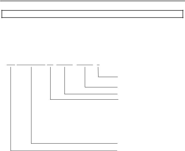
Figure 1: RediStart MVRMX3 Series Model Numbers
CFMVRMX18-3500-4160-1
1 - Nema 1
3R - Nema 3R
12 - Nema 12
Voltage
HP
12 - 2300 Volts
- 2400 Volts
- 3300 Volts
18 - 4160 Volts
- 4800 Volts
- 7200 Volts
MV MX3 Control
Combination Fusable
Example of Model Number: CFMVRMX18-3500-4160-1
A Combination Fusable RediStart starter with MV MX3 control, 4160 Volts, 3500 Horse Power, NEMA 1 Enclosure.
5

1 - INTRODUCTION
General Overview Of A Reduced Voltage Starter
General Overview |
The RediStart MVRMX3 motor starter is a microprocessor-controlled starter for single or three-phase motors. |
|
|
The starter can be custom designed for specific applications. A few of the features are: |
|
|
• |
Solid state design |
|
• Reduced voltage starting and soft stopping |
|
|
• Closed-loop motor current control, power (kW) control, torque control |
|
|
• |
Programmable motor protection |
|
• |
Programmable operating parameters |
|
• |
Programmable metering |
|
• |
Communications |
|
Each starter can operate within applied frequency values 23 to 72Hz and line voltage of: |
|
|
2,200VAC to 2,400VAC |
|
|
3,300VAC to 4,800VAC |
|
|
4,800VAC to 7,200VAC |
|
|
10,000VAC to 12,000VAC |
|
|
12,470VAC to 13,800VAC |
|
|
The starter can be programmed for any motor FLA and all of the common motor service factors. It enables |
|
|
operators to control both motor acceleration and deceleration. The RediStart MVRMX3 can also protect the |
|
|
motor and its load from damage that could be caused by incorrect phase order wiring. |
|
|
The starter continually monitors the amount of current being delivered to the motor. This protects the motor |
|
|
from overheating or drawing excess current. |
|
Features |
The enhanced engineering features of the starter include: |
|
|
• |
Multiple frame sizes |
|
• |
Universal voltage operation |
|
• |
Universal frequency operation |
|
• Programmable motor overload multiplier |
|
|
• Controlled acceleration and deceleration |
|
|
• |
Phase rotation protection |
|
• |
Regulated current control |
|
• Electronic motor thermal overload protection |
|
|
• Electronic over/under current protection |
|
|
• |
Single phase protection |
|
• Line-to-line current imbalance protection |
|
|
• |
Stalled motor protection |
|
• |
Programmable metering |
|
• |
Passcode protected |
|
• |
Programmable Relays |
|
• Analog output with digital offset and span adjustment |
|
|
• Analog input with digital offset and span adjustment |
|
|
• Voltage and Current Accuracy of 3% |
|
|
• Slow speed (Cyclo Conversion) 1.0 – 40.0% forward and reverse |
|
|
• Motor Winding Heater (Anti-Condensation) |
|
|
• Anti-windmilling brake |
|
|
• |
PTC Thermistor |
|
• |
99 Event Recorder |
|
• |
9 Fault Log |
|
• |
Real Time Clock |
|
• Zero Sequence Ground Fault |
|
|
• |
Backspin Timer |
|
• |
Starts per Hour |
|
• |
Time between Starts |
|
• PORT (Power Outage Ride Through) |
|
|
• 16 RTD with O/L Biasing |
|
|
• |
D.C. Injection Braking |
6

2 Technical Specifications
7

2 - TECHNICAL SPECIFICATIONS
Technical Specifications
2.1General Information
The physical specifications of the starter vary depending upon its configuration. The applicable motor current determines the configuration and its specific application requirements. Specifications are subject to change without notice.
This document covers the control electronics and several power sections:
•MX3 Control Card Set
•Power Stacks with inline and bypass vacuum contactors
2.2Electrical Ratings
2.2.1Terminal Points and Functions
Table 1: Terminals
Function |
Terminal |
Terminal Number |
Description |
|
Block |
|
|||
|
|
|
|
|
Control Power |
TB1 |
G, ground |
96 – 144 VAC input, 50/60 Hz |
|
|
|
N, 120VAC neutral |
45VA required for control card |
|
|
|
N, 120VAC neutral |
|
|
|
|
L, 120VAC line |
|
|
|
|
L, 120VAC line |
|
|
|
|
|
|
|
Relay 1 (R1) |
TB2 |
NO1:Normally Open Contact |
Relay Output, SPDT form C |
|
|
|
RC1:Common |
NO Contact (resistive) |
NC Contact(resistive) |
|
|
NC1: Normally Closed Contact |
5A at 250VAC |
3A at 250VAC |
|
|
|
5A at 125VAC |
3A at 125VAC |
|
|
|
5A at 30VDC |
3A at 30VDC |
|
|
|
1250VA |
750VA |
|
|
|
|
|
Relay 2 (R2) |
TB2 |
NO2: Normally Open Contact |
Relay Output, SPDT form C |
|
|
|
RC2: Common Contact |
NO Contact (resistive) |
NC Contact(resistive) |
|
|
NC2: Normally Closed Contact |
5A at 250VAC |
3A at 250VAC |
|
|
|
5A at 125VAC |
3A at 125VAC |
|
|
|
5A at 30VDC |
3A at 30VDC |
|
|
|
1250VA |
750VA |
|
|
|
|
|
Relay 3 (R3) |
TB2 |
NO3: Normally Open Contact |
10A at 250VAC |
|
|
|
RC3: Common Contact |
10A at 125VAC |
|
|
|
NC3: Normally Closed Contact |
10A at 30VDC |
|
|
|
|
2500VA |
|
|
|
|
|
|
Relay 4 (R4) |
J3 |
R4A: Normally Open Contact |
Relay Output, SPST-NO form A |
|
|
|
R4B: Normally Open Contact |
Resistive: |
|
|
|
|
5A at 250VAC |
|
|
|
|
5A at 125VAC |
|
|
|
|
5A at 30VDC |
|
|
|
|
1250VA |
|
|
|
|
|
|
Relay5 (R5) |
J3 |
R5A: Normally Open Contact |
Relay Output, SPST-NO form A |
|
|
|
R5B: Normally Open Contact |
Resistive: |
|
|
|
|
5A at 250VAC |
|
|
|
|
5A at 125VAC |
|
|
|
|
5A at 30VDC |
|
|
|
|
1250VA |
|
|
|
|
|
|
Relay6 (R6) |
J3 |
R6A: Normally Open Contact |
Relay Output, SPST-NO form A |
|
|
|
R6B: Normally Open Contact |
Resistive: |
|
|
|
|
5A at 250VAC |
|
|
|
|
5A at 125VAC |
|
|
|
|
5A at 30VDC |
|
|
|
|
1250VA |
|
|
|
|
|
|
Digital Inputs |
TB3 |
1: Start |
120VAC digital input |
|
|
|
2: DI1 |
2500V optical isolation |
|
|
|
3: DI2 |
4mA current draw |
|
|
|
4: DI3 |
Off: 0-35VAC |
|
|
|
5: Common |
On: 60-120VAC |
|
|
|
|
|
|
Digital Inputs |
J6 |
1: DI4 |
120VAC digital input |
|
|
|
2: DI5 |
2500V optical isolation |
|
|
|
3: DI6 |
4mA current draw |
|
|
|
4: DI7 |
Off: 0-35VAC |
|
|
|
5: DI8 |
On: 60-120VAC |
|
|
|
6: Common |
|
|
|
|
|
|
|
8

2 - TECHNICAL SPECIFICATIONS
Function |
Terminal |
Terminal Number |
Description |
|
Block |
||||
|
|
|
||
Serial Comm |
TB4 |
1: B+ |
Modbus RTU serial communication port. |
|
|
|
2: A- |
RS-485 interface |
|
|
|
3: COM |
19.2k baud maximum |
|
|
|
|
2500V Isolation |
|
|
|
|
|
|
Analog I/O |
TB5 |
1: Ain Power |
Input: |
|
|
|
2: Ain + |
Voltage or Current |
|
|
|
3: Ain - |
Voltage: 0-10VDC, 67K impedance |
|
|
|
4: Common |
Current: 0-20mA, 500 impedance |
|
|
|
5: Aout |
|
|
|
|
6: Common |
Output: |
|
|
|
7: Shield |
Voltage or Current |
|
|
|
|
Voltage: 0-10VDC, 120mA maximum |
|
|
|
|
Current: 0-20mA, 500 load maximum |
|
|
|
|
|
|
PTC Thermistor Input |
J7 |
1: Motor PTC |
Positive Temperature Coefficient Thermistor |
|
|
|
2: Motor PTC |
- Trip resistance 3.5K, ± 300 Ohms. |
|
|
|
|
- Reset resistance 1.65K, ± 150 Ohms. |
|
|
|
|
- Open terminal voltage is 15V. |
|
|
|
|
- PTC voltage at 4Kohms = 8.55V. (>7.5V) |
|
|
|
|
- Response time adjustable between 1 and 5 seconds. |
|
|
|
|
- Maximum cold resistance of PTC chain = 1500 Ohms. |
|
|
|
|
|
|
Zero Sequence |
J15 |
1: CT input |
Zero Sequence Ground Fault |
|
Ground Fault |
|
2: CT input |
CT Type: 50:0.025 (2000:1 ratio) |
|
|
|
|
Measurement range: 0.1A - 25.0 Amps Accuracy : +/- 3% |
|
|
|
|
Burden at 25Amps : 0.0089VA. |
|
|
|
|
|
|
Display |
RJ45 |
|
Door Mounted Display Connector |
|
|
|
|
|
|
SCR |
SCR 1A-F |
ISO 1 to ISO 18 |
Fiber Optic connector |
|
|
SCR 2A-F |
|
|
|
|
SCR 3A-F |
|
|
|
|
|
|
|
|
Stack OT |
Phase 1 |
LS1 |
Fiber Optic connector |
|
|
Phase 2 |
LS2 |
|
|
|
Phase 3 |
LS3 |
|
|
|
|
|
|
|
Phase C.T. |
J10 |
1: CT1+ |
Phase CT Connector |
|
|
|
2: CT1 |
|
|
(5 Amp input) |
|
3: CT2+ |
|
|
|
|
4: CT2 |
|
|
|
|
5: CT3+ |
|
|
|
|
6: CT3 |
|
|
|
|
|
|
Wire Gauge: The terminals can support 1- 14 AWG wire or 2-16 AWG wires or smaller.
Torque Rating: The terminals on the control cards have a torque rating of 5.0-inch lb. or 0.56Nm. This MUST be followed or damage will occur to the terminals.
NOTE: Refer to Control Card Layout starting on page 28.
9

2 - TECHNICAL SPECIFICATIONS
2.2.2Measurements and Accuracies
Table 2: Measurements and Accuracies
Internal Measurements |
|
|
|
CT Inputs |
Conversion: True RMS, Sampling @ 1.562kHz |
||
Range: 1-6400A |
|||
|
|||
Line Voltage Inputs |
Conversion: True RMS, Sampling @ 1.562kHz |
||
Range: 2,000 - 8,000VAC, 23 to 72 Hz |
|||
|
|||
Metering |
|
|
|
Current |
0 |
– 40,000 Amps ± 3% |
|
Voltage |
0 |
– 8,000 Volts ± 3% |
|
0 |
– 9,999 MW ± 5% |
||
Watts |
|||
0 |
– 9,999 MVA ± 5% |
||
Volts-Amps |
|||
0 |
– 10,000 MWh ± 5% |
||
Watt-Hours |
|||
-0.01 to +0.01 (Lag & Lead) ± 5% |
|||
PF |
|||
23 – 72 Hz ± 0.1 Hz |
|||
Line Frequency |
|||
5 |
– 100% FLA ± 5% (Machine Protection) |
||
Ground Fault |
± 3 seconds per 24 hour period |
||
Run Time |
Accuracy ± 3% of full scale (10 bit) |
||
Analog Input |
Accuracy ±2% of full scale (12 bit) |
||
Analog Output |
0.1 – 25.0 Amps ± 3% |
||
Zero Seq GF |
NOTE: Percent accuracy is percent of full scale of the given ranges, Current = Motor FLA, |
||
|
Voltage = 8,000V, Watts/Volts-Amps/Watt-Hours = Motor & Voltage range |
||
2.2.3List of Motor Protection Features
•ANSI 14 – Speed Switch and Tachometer Trip
•ANSI 19 – Reduced Voltage Start
•ANSI 27 / 59 – Adjustable over/under voltage protection (Off or 1 to 40%, time 0.1 to 90.0 sec. in 0.1 sec. intervals, independent over and under voltage levels)
•ANSI 37 – Undercurrent detection (Off or 5 to 100% and time 0.1 to 90.0 sec. in 0.1 sec. intervals)
•ANSI 38 – Bearing RTD
Other RTD
Open RTD Alarm
•ANSI 46 – Current imbalance detection (Off or 5 to 40%)
•ANSI 47 – Phase rotation (selectable ABC, CBA, Insensitive, or Single Phase)
•ANSI 48 – Adjustable up-to-speed / stall timer (1 to 900 sec. in 1 sec. intervals)
•ANSI 49 – Stator RTD
•ANSI 50 – Instantaneous electronic overcurrent trip
•ANSI 51 – Electronic motor overload (Off, class 1 to 40, separate starting and running curves available)
•ANSI 51 – Overcurrent detection (Off or 50 to 800% and time 0.1 to 90.0 sec. in 0.1 sec. intervals)
•ANSI 51G – Residual Ground fault detection (Off or 5 to 100% of motor FLA)
Zero Sequence Ground Fault Detection (Off, 0.1 - 25Amps)
ANSI 66 – Starts/Hour & Time Between Starts
Restart Block (Backspin Timer)
•ANSI 74 – Alarm relay output available
•ANSI 81 – Over / Under Frequency
•ANSI 86 – Overload lockout
•Single Phase Protection
•Shorted SCR Detection
•Mechanical Jam
10
2 - TECHNICAL SPECIFICATIONS
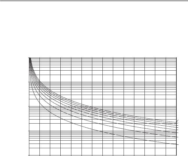
2.2.4Solid State Motor Overload
The MVRMX3 control has an advanced I2t electronic motor overload (OL) protection function. For optimal motor protection the MVRMX3 control has forty standard NEMA style overload curves available for use. Separate overloads can be programmed, one for acceleration and another for normal running operation. The overloads can be individual, the same or completely disabled if necessary. The MVRMX3 motor overload function also implements a NEMA based current imbalance overload compensation, RTD Biasing, user adjustable hot and cold motor compensation and user adjustable exponential motor cooling.
Figure 2: Commonly Used Overload Curves
|
10000 |
|
|
|
|
|
|
|
|
|
|
|
|
|
|
|
1000 |
|
|
|
|
|
|
|
|
|
|
|
|
|
|
| <![if ! IE]> <![endif]>toTrip |
|
|
|
|
|
|
|
|
|
|
|
|
|
|
|
| <![if ! IE]> <![endif]>Seconds |
100 |
|
|
|
|
|
|
|
|
|
|
|
|
|
|
|
|
|
|
|
|
|
|
|
|
|
|
|
|
|
|
|
|
|
|
|
|
|
|
|
|
|
|
|
|
|
Class 40 |
|
|
|
|
|
|
|
|
|
|
|
|
|
|
|
Class 35 |
|
|
|
|
|
|
|
|
|
|
|
|
|
|
|
Class 30 |
|
|
|
|
|
|
|
|
|
|
|
|
|
|
|
Class 25 |
|
10 |
|
|
|
|
|
|
|
|
|
|
|
|
|
Class 20 |
|
|
|
|
|
|
|
|
|
|
|
|
|
|
Class 15 |
|
|
|
|
|
|
|
|
|
|
|
|
|
|
|
|
|
|
|
|
|
|
|
|
|
|
|
|
|
|
|
|
Class 10 |
|
|
|
|
|
|
|
|
|
|
|
|
|
|
|
Class 5 |
|
1 |
|
|
|
|
|
|
|
|
|
|
|
|
|
|
|
100 |
150 |
200 |
250 |
300 |
350 |
400 |
450 |
500 |
550 |
600 |
650 |
700 |
750 |
800 |
Current % (FLA)
The motor overload will NOT trip when the current is less than motor Full Load Amps (FLA) * Service Factor (SF). The motor overload "pick up" point current is at motor Full Load Amps (FLA) * Service Factor (SF).
The motor overload trip time will be reduced when there is a current imbalance present.
NOTE: Refer to Theory of Operation, Chapter 7 in section 7.1 for more motor overload details and a larger graph. Refer to http://www.benshaw.com/olcurves.html for an automated overload calculator.
11

2 - TECHNICAL SPECIFICATIONS
2.2.5CT Ratios
Table 3: CT Ratios
CT Ratio (x:5) |
Minimum FLA |
Maximum FLA |
|
(A rms) |
(A rms) |
||
|
|||
50:5 |
11 |
45 |
|
150:5 |
33 |
135 |
|
250:5 |
55 |
225 |
|
800:5 |
176 |
720 |
|
2000:5 |
440 |
1800 |
|
5000:5 |
1100 |
4500 |
2.2.6Optional RTD Module Specifications
The starter has the option of operating with up to two Benshaw SPR-100P remote RTD modules.
Table 4: Remote RTD Module Specifications |
||
|
|
|
Model Number |
SPR-100P |
|
RTD Type |
100 Platinum, 3 lead |
|
TCR ( ) |
0.00385 / / C |
|
(DIN 43760) |
||
|
||
Maximum Lead Resistance |
25 per lead |
|
Recommended Lead Resistance |
Less than 16 per lead |
|
Shorted Lead Detection |
< 60 |
|
Open Lead Detection |
> 260 |
|
RTD Sensing Current |
10 mA DC |
|
RTD Sensing Voltage |
10V DC maximum |
|
Range |
0 to 200 C (32 to 392 F) |
|
Resolution |
1 C (1.8 F) |
|
Accuracy |
1.0% full scale ( 2 C or 3.6 F) |
|
Sampling Rate |
1 RTD per second |
|
Number of RTDs |
8 |
|
Input Voltage |
24 Volts DC 20%, 2.5W |
|
Communication Type |
Modbus RTU, RS-485, 19.2Kbps |
|
Modbus® Addresses |
16 to 23 |
|
Operating Environment |
-40 to 60 C (-40 to 140 F), up to 95% R.H., non-condensing |
|
Terminal Strips |
Accepts one or two stranded copper wires of the same size |
|
from 12 to 30 AWG |
||
|
||
Dimensions |
5 ½" W x 3 ½" H x 2 ¼" D |
|
Listing |
cUL |
|
12
2 - TECHNICAL SPECIFICATIONS
2.2.7Optional Zero Sequence Ground Fault CT
The Benshaw BICT 2000/1-6 CT has the following excitation curve.
Figure 3: BICT2000/1-6 Excitation Curve
13

2 - TECHNICAL SPECIFICATIONS
Sample RediStart MVRMX3 Unit
2.3Sample RediStart MVRMX3 Unit
LINE BUS
SECTION
DISCONNECT SECTION
ZERO SEQUENCE GROUND FAULT CURRENT TRANSFORMER (GFCT) OPTIONAL
MEDIUM
VOLTAGE
SECTION
HORIZONTAL POWER BUS
TIN PLATED COPPER
OPTIONAL
LINE
DISCONNECT GROUNDING ARM
DISCONNECT SWITCH 400 AMP
MEDIUM VOLTAGE DOOR
ELECTRO-MECHANICAL INTERLOCK
MEDIUM VOLTAGE DIVIDER CARD
MOTOR STARTING FUSES (R RATED)
CURRENT TRANSFORMERS (CT)
BYPASS CONTACTOR (BP)
c/w 2-HOLE COPPER LANDING PAD
INLINE CONTACTOR (IL)
T1 T2 T3
FIBER OPTIC
PHASE ASSEMBLY
1kVA, 1-PHASE  TRANSFORMER
CONTROL WIRE WAY 2"W X 4"H OPTIONAL
COPPER GROUND BUS (2"W X 1/4"T)
NOTE: This is only a sample diagram drawing for component identification purposes. Component locations may change to meet end users specifications.
14

2 - TECHNICAL SPECIFICATIONS
|
|
|
|
Environmental Conditions |
|
|
|
|
|
|
|
2.4 |
Environmental Conditions |
|
|
|
|
|
|
|
Table 6: Environmental Ratings |
||
|
|
|
|
|
|
|
|
Operating Temperatures |
|
-10°C to +40°C (14°F to 104°F)enclosed |
|
|
|
|
|
-10°C to +50°C (14°F to 122°F)open |
|
|
|
Storage Temperatures |
|
-20°C to +70°C (-4°F to 155°F) |
|
|
|
Humidity |
|
0% to 95% non condensing |
|
|
|
Altitude |
|
1000m (3300ft) without derating |
|
|
|
Maximum Vibration |
|
5.9m/s2 (19.2ft/s2 ) [0.6G] |
|
|
|
Cooling |
|
Natural convection |
|
|
|
|
|
(Fans optional) |
|
Altitude Derating
2.5Altitude Derating
Benshaw's starters are capable of operating at altitudes up to 3,300 feet (1000 meters) without requiring altitude derating. Table 7 provides the derating percentage to be considered when using a starter above 3,300 feet (1000 meters).
Table 7: Altitude Derating
|
Altitude |
Percent Derating (Amps) |
|
3300 Feet |
|
1006 meters |
0.0% |
4300 Feet |
|
1311 meters |
3.0% |
5300 Feet |
|
1615 meters |
6.0% |
6300 Feet |
|
1920 meters |
9.0% |
7300 Feet |
|
2225 meters |
12.0% |
8300 Feet |
|
2530 meters |
15.0% |
9300 Feet |
|
2835 meters |
18.0% |
For derating above 10,000 feet consult Benshaw Inc.
Real Time Clock
2.6Real Time Clock
The MX3 comes with a real time clock. The user can enter the actual time and the starter will use this time when it logs faults in the fault recorder as well as events in the event recorder. This can help with troubleshooting. The system clock does not recognize daylight savings time.
Accuracy: +- 1 minute per month
Range: 1/1/1972 to 1/1/2107 with automatic leap year compensation.
Approvals
2.7Approvals
MX3 Control Card Set is UL, cUL Recognized
Certificate of Compliance
2.8Certificate of Compliance
CE Mark, see Appendix E on page 186.
15

2 - TECHNICAL SPECIFICATIONS
NOTES:
16

3 |
Installation |
17
3 - INSTALLATION
Before You Start
3.1Before You Start
3.1.1Installation Precautions
Inspection
Before storing or installing the RediStart MVRMX3 Series Starter, thoroughly inspect the device for possible shipping damage. Upon receipt:
•Remove the starter from its package and inspect exterior for shipping damage. If damage is apparent, notify the shipping agent and your sales representative.
•Open the enclosure and inspect the starter for any apparent damage or foreign objects. Ensure that all of the mounting hardware and terminal connection hardware is properly seated, securely fastened, and undamaged.
•Ensure all connections and wires are secured.
•Read the technical data label affixed to the starter and ensure that the correct horsepower and input voltage for the application has been purchased.
General Information
Installation of some models may require halting production during installation. If applicable, ensure that the starter is installed when production can be halted long enough to accommodate the installation. Before installing the starter, ensure:
•The wiring diagram (supplied separately with the starter) is correct for the required application.
•The starter is the correct current rating and voltage rating for the motor being started.
• All of the installation safety precautions are followed.
• The correct power source is available.
•The starter control method has been selected.
•The connection cables have been obtained (lugs) and associated mounting hardware.
•The necessary installation tools and supplies are procured.
•The installation site meets all environmental specifications for the starter NEMA/CEMA rating.
•The motor being started has been installed and is ready to be started.
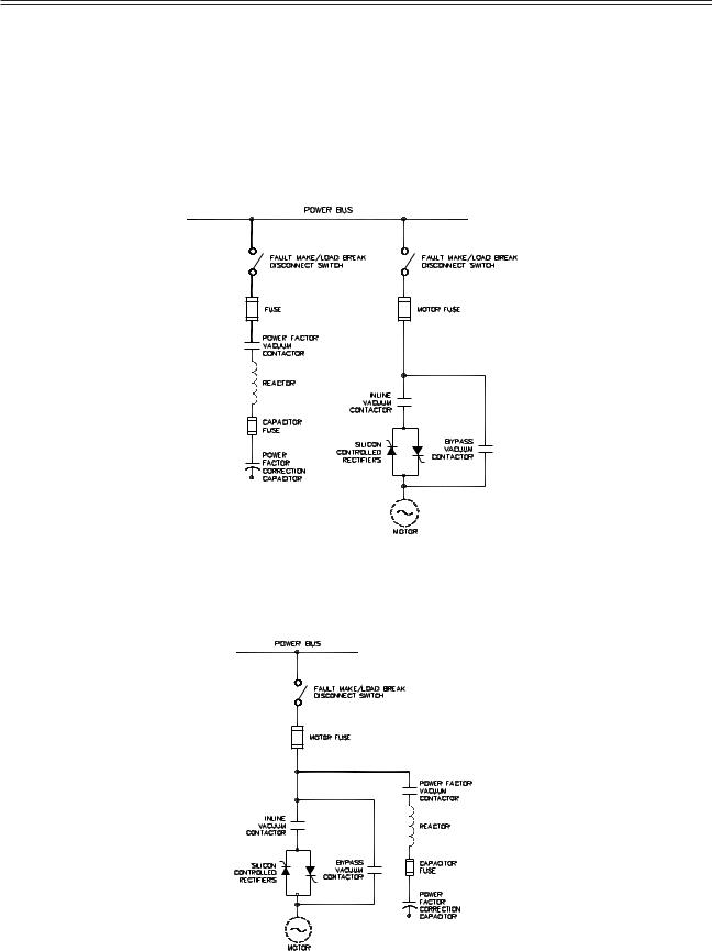
•Any power factor correction capacitors (PFCC) are installed on the power source side of the starter and not on the motor side.
Failure to remove power factor correction or surge capacitors from the load side of the starter will result in serious damage to the starter that will not be covered by the starter warranty. The capacitors must be connected to the line side of the starter. The up-to-speed (UTS) contact can be used to energize the capacitors after the motor has reached full speed.
3.1.2Safety Precautions
To ensure the safety of the individuals installing the starter, and the safe operation of the starter, observe the following guidelines:
• Ensure that the installation site meets all of the required environmental conditions (refer to Site Preparation, page 19).
• LOCK OUT ALL SOURCES OF POWER.
• Install circuit disconnecting devices (i.e., circuit breaker, fused disconnect or non-fused disconnect) if they were not previously installed by the factory as part of the package.
•Install short circuit protection (i.e., circuit breaker or fuses) if not previously installed by the factory as part of the package.
•Follow all NEC (National Electrical Code) and/or C.S.A. (Canadian Standards Association) standards or Local Codes as applicable.
•Remove any foreign objects from the interior of the enclosure, especially wire strands that may be left over from installation wiring.
•Ensure that a qualified electrician installs wiring.
•Ensure that the individuals installing the starter are wearing ALL protective eyewear and clothing.
•Ensure the starter is protected from debris, metal shavings and any other foreign objects.
The opening of the branch circuit protective device may be an indication that a fault current has been interrupted. To reduce the risk of electrical shock, current carrying parts and other components of the starter should be inspected and replaced if damaged.
18

3 - INSTALLATION
Installation Considerations
3.2Installation Considerations
3.2.1Site Preparation
General Information
Before the starter can be installed, the installation site must be prepared. The customer is responsible for:
•Providing the correct power source
•Providing the correct power protection
•Selecting the control mechanism
•Obtaining the connection cables, lugs and all other hardware
•Ensuring the installation site meets all environmental specifications for the enclosure NEMA rating
•Installing and connecting the motor
Power Cables
The power cables for the starter must have the correct NEC/CSA current rating for the unit being installed. Depending upon the model, the power cables can range from a single #14 AWG conductor to four 750 MCM cables. (Consult local and national codes for selecting wire size).
Site Requirements
The installation site must adhere to the applicable starter NEMA/CEMA rating. For optimal performance, the installation site must meet the appropriate environmental and altitude requirements.
3.2.2EMC Installation Guidelines
General |
In order to help our customers comply with European electromagnetic compatibility standards, Benshaw Inc. has |
|
developed the following guidelines. |
Attention |
This product has been designed for Class A equipment. Use of the product in domestic environments may cause radio |
|
interference, in which case the installer may need to use additional mitigation methods. |
Enclosure |
Install the product in a grounded metal enclosure. |
Grounding |
Connect a grounding conductor to the screw or terminal provided as standard on each controller. Refer to layout/power |
|
wiring schematic for grounding provision location. |
Wiring |
Refer to Wiring Practices on page 21. |
Filtering |
To comply with Conducted Emission Limits (CE requirement), a high voltage (1000V or greater) 0.1 uF capacitor |
|
should be connected from each input line to ground at the point where the line enters the cabinet. |
3.2.3R-Rated Motor Starter Fuses
R-rated fuses are current-limiting, high interrupting rating fuses intended for the short-circuit protection of medium voltage motors and motor controllers. R-rated fuses are back up fuses that have a minimum interrupting rating, and must be coordinated with overload relays in combination motor starters.
3.2.4Use of Electro-Mechanical Brakes
If an electro-mechanical brake is used with the starter, it must be powered from the line side of the starter to ensure full voltage is applied to the brake during a start so it will properly release. A programmable relay can be configured as a run relay and then used to pull-in a contactor to power the brake whenever the starter is providing power to the motor.
3.2.5Reversing Contactor
If the application requires a reversing contactor, it should be connected on the output side (load) of the soft starter. The contactor must be closed before starting the soft starter. The soft starter must be off before switching the direction of the reversing contactor. The reversing contactor must never be switched while the soft starter is operating.
19
3 - INSTALLATION
3.2.6Use of Power Factor Capacitors
Power factor correction capacitors and surge capacitors CAN NOT be connected between the starter and the motor. These devices can damage the SCRs during ramping. These devices appear like a short circuit to the SCR when it turns on, which causes a di/dt level greater than the SCR can handle. If used, power factor correction capacitors or surge capacitors must be connected ahead of the starter and sequenced into the power circuit after the start is completed. A programmable relay can be configured as an up-to-speed (UTS) relay and then used to pull-in a contactor to connect the capacitors after the motor has reached full speed.
Figure 4: Separate Power Factor Correction Disconnect
NOTE: If the motor manufacturer supplies surge capacitors they must be removed before starting.
Figure 5: Integral Power Factor Correction Disconnect
20

3 - INSTALLATION
Mounting Considerations
3.3Mounting Considerations
3.3.1Bypassed Starters
Provisions should be made to ensure that the temperature inside the enclosure never rises above 50°C. If the temperature inside the enclosure is too high, the starter can be damaged or the operational life can be reduced.
Wiring Considerations
3.4Wiring Considerations
3.4.1Wiring Practices
When making power and control signal connections, the following should be observed:
•Never connect input AC power to the motor output terminals T1/U, T2/V, or T3/W.
•Power wiring to the motor must have the maximum possible separation from all other wiring. Do not run control wiring in the same conduit; this separation reduces the possibility of coupling electrical noise between circuits. Minimum spacing between metallic conduits containing different wire groups should be three inches (8cm).
•Minimum spacing between different wiring groups in the same tray should be six inches.
•Wire runs outside an enclosure should be run in metallic conduit or have shielding/armor with equivalent attenuation.
•Whenever power and control wiring cross it should be at a 90 degree angle.
•Different wire groups should be run in separate conduits.
•With a reversing application, the starter must be installed in front of the reversing contactors.
NOTE: Local electrical codes must be adhered to for all wiring practices.
3.4.2Considerations for Control and Power Wiring
Control wiring refers to wires connected to the control terminal strip that normally carry 24V to 115V and Power wiring refers to wires connected to the line and load terminals that normally carries 2200VAC to 7200VAC respectively. Select power wiring as follows:
•Use only UL or CSA recognized wire.
•Grounding must be in accordance with NEC, CEC or local codes. If multiple starters are installed near each other, each must be connected to ground. Take care to not form a ground loop. The grounds should be connected in a STAR configuration.
3.4.3Considerations for Signal Wiring
Signal wiring refers to the wires connected to the control terminal strip that are low voltage signals, below 15V.
•Shielded wire is recommended to prevent electrical noise interference from causing improper operation or nuisance tripping.
•Signal wire rating should carry as high of a voltage rating as possible, normally at least 300V.
•Routing of signal wire is important to keep as far away from control and power wiring as possible.
3.4.4Meggering a Motor
If the motor needs to be meggered, remove the motor leads from the starter before conducting the test. Failure to comply may damage the SCRs and WILL damage the control board, which WILL NOT be replaced under warranty.
3.4.5High Pot Testing
If the starter needs to be high pot tested, perform a DC high pot test. The maximum high pot voltage must not exceed 2.0 times rated RMS voltage + 2000VAC (High pot to 75% of factory). Failure to comply WILL damage the control board, which WILL NOT be replaced under warranty. An example to find the maximum high pot voltage is (2.0 * rated RMS voltage + 2000) * 0.75.
21
3 - INSTALLATION
Typical Wiring Schematics
3.5Typical Wiring Schematics
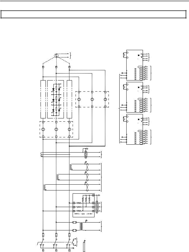
3.5.1MVRMX3 Power Wiring Schematic
Figure 6: MVRMX3 Power Wiring Schematic
|
|
|
|
<![if ! IE]> <![endif]>3Ø50/60Hz. 2200-6900VAC |
|
|
<![if ! IE]> <![endif]>T1 T2 |
<![if ! IE]> <![endif]>BIPC-450100-01 |
<![if ! IE]> <![endif]>MOTPTCTERMINALS |
<![if ! IE]> <![endif]>MOTORTHERMISTORS |
<![if ! IE]> <![endif]>(SUPPLIEDBYOTHER) |
|
<![if ! IE]> <![endif]>T1 |
|
|
<![if ! IE]> <![endif]>T2 |
|
<![if ! IE]> <![endif]>T3 |
|
|
|
|
|
| <![if ! IE]> <![endif]>SCRs |
<![if ! IE]> <![endif]>PHASE1SCRSTACKASSEMBLY |
<![if ! IE]> <![endif]>(SAMEASPHASE2SCRSTACKASSEMBLY) |
<![if ! IE]> <![endif]>PHASE2SCRSTACKASSEMBLY. |
<![if ! IE]> <![endif]>AK AG CK CG EK EG SCRA SCRC SCRE |
<![if ! IE]> <![endif]>SCRB SCRD SCRF BG BK DG DK FG FK |
<![if ! IE]> <![endif]>PHASE3SCRSTACKASSEMBLY |
<![if ! IE]> <![endif]>(SAMEASPHASE2SCRSTACKASSEMBLY) |
|
<![if ! IE]> <![endif]>BYPASSCONTACTOR |
<![if ! IE]> <![endif]>BP |
<![if ! IE]> <![endif]>BP |
| <![if ! IE]> <![endif]>CONTACTOR |
<![if ! IE]> <![endif]>IL |
<![if ! IE]> <![endif]>IL |
<![if ! IE]> <![endif]>IL |
| <![if ! IE]> <![endif]>IN-LINE |
|
|
|
| <![if ! IE]> <![endif]>CT4-GFCT ZEROSEQUENCE GROUNDFAULTCT (OPTIONAL) |
|
|
|
| <![if ! IE]> <![endif]>5ACT |
<![if ! IE]> <![endif]>CT3 |
| <![if ! IE]> <![endif]>5ACT |
<![if ! IE]> <![endif]>CT2 |
| <![if ! IE]> <![endif]>5ACT |
<![if ! IE]> <![endif]>CT1 |
|
|
|
<![if ! IE]> <![endif]>TB5 |
|
<![if ! IE]> <![endif]>R6 |
<![if ! IE]> <![endif]>R5 |
<![if ! IE]> <![endif]>R4 |
| <![if ! IE]> <![endif]>TB1 |
<![if ! IE]> <![endif]>R1 |
|
<![if ! IE]> <![endif]>TB2 |
| <![if ! IE]> <![endif]>TB3 |
<![if ! IE]> <![endif]>R2 |
|
<![if ! IE]> <![endif]>TB4 |
| <![if ! IE]> <![endif]>TB6 |
<![if ! IE]> <![endif]>R3 |
|
<![if ! IE]> <![endif]>TB7 |
BIPC-300032-01 |
|
|
<![if ! IE]> <![endif]>TX1 |
| <![if ! IE]> <![endif]>4160VAC |
<![if ! IE]> <![endif]>120VAC |
<![endif]>ON PHASE
<![if ! IE]><![endif]>O/T SWITCH
<![if ! IE]><![endif]>ON PHASE
<![if ! IE]><![endif]>O/T SWITCH
<![if ! IE]><![endif]>BP
<![if ! IE]><![endif]>TO TX2
<![if ! IE]><![endif]>ON PHASE
<![if ! IE]><![endif]>O/T SWITCH
| <![if ! IE]> <![endif]>450100-01 |
<![if ! IE]> <![endif]>J15 |
| <![if ! IE]> <![endif]>BIPC- |
|
| <![if ! IE]> <![endif]>450100-01 |
<![if ! IE]> <![endif]>J10 |
| <![if ! IE]> <![endif]>BIPC- |
|
| <![if ! IE]> <![endif]>450100-01 |
<![if ! IE]> <![endif]>J8 |
| <![if ! IE]> <![endif]>BIPC- |
|
| <![if ! IE]> <![endif]>BIPC-450100-01 |
<![if ! IE]> <![endif]>120VAC |
<![endif]>1 2
<![if ! IE]><![endif]>1 2 3 4
<![if ! IE]><![endif]>1 2
<![if ! IE]><![endif]>1 2 3 4
<![if ! IE]><![endif]>1 2
<![if ! IE]><![endif]>1 2 3 4
| <![if ! IE]> <![endif]>J3O/T |
|
<![if ! IE]> <![endif]>CARD |
| <![if ! IE]> <![endif]>J1 |
<![if ! IE]> <![endif]>BIPC-300047-01 |
<![if ! IE]> <![endif]>FIBEROPTICGATEDRIVER |
| <![if ! IE]> <![endif]>J3O/T |
|
<![if ! IE]> <![endif]>CARD |
| <![if ! IE]> <![endif]>J1 |
<![if ! IE]> <![endif]>BIPC-300047-01 |
<![if ! IE]> <![endif]>FIBEROPTICGATEDRIVER |
| <![if ! IE]> <![endif]>J3O/T |
|
<![if ! IE]> <![endif]>CARD |
| <![if ! IE]> <![endif]>J1 |
<![if ! IE]> <![endif]>BIPC-300047-01 |
<![if ! IE]> <![endif]>FIBEROPTICGATEDRIVER |
| <![if ! IE]> <![endif]>L1 |
<![if ! IE]> <![endif]>L2 |
<![if ! IE]> <![endif]>L3 |
<![if ! IE]> <![endif]>BIPC-450100-01 DI3 |
<![if ! IE]> <![endif]>GROUNDBUS |
|
<![if ! IE]> <![endif]>3Ø50/60Hz. |
<![if ! IE]> <![endif]>2200-6900VAC |
|
|
<![endif]> PWR
PWR OK
OK
STATUS ISO6
 ISO5
ISO5
 ISO4
ISO4
 ISO3
ISO3
 ISO2
ISO2
 ISO1
ISO1

<![endif]> PWR
PWR OK
OK
STATUS ISO6
 ISO5
ISO5
 ISO4
ISO4
 ISO3
ISO3
 ISO2
ISO2
 ISO1
ISO1

<![endif]> PWR
PWR OK
OK
STATUS ISO6
 ISO5
ISO5
 ISO4
ISO4
 ISO3
ISO3
 ISO2
ISO2
 ISO1
ISO1

<![endif]>TO PHASE 3
FS3 F3F F3E F3D F3C F3B F3A
<![if ! IE]><![endif]>TO PHASE 2
FS2 F2F F2E F2D F2C F2B F2A
<![if ! IE]><![endif]>TO PHASE 1
FS1 F1F F1E F1D F1C F1B F1A
| <![if ! IE]> <![endif]>SCRs |
|
| <![if ! IE]> <![endif]>BIPC-450100-01 |
<![if ! IE]> <![endif]>PHASE3 |
| <![if ! IE]> <![endif]>SCRs |
|
| <![if ! IE]> <![endif]>BIPC-450100-01 |
<![if ! IE]> <![endif]>PHASE2 |
| <![if ! IE]> <![endif]>SCRs |
|
| <![if ! IE]> <![endif]>BIPC-450100-01 |
<![if ! IE]> <![endif]>PHASE1 |
22
 Loading...