

Operating manual
pro
®
Mehrsprachige Anleitung unter
BENNING
BENNING
L1
L2
L3
BENNING
BENNING
www.benning.de
Multilingual manuals at
BENNING
BENNING
TRITEST
®
pro
TRITEST
L3
L2
L1
D F
BENNING
BENNING
8
9
J
BENNING
1
2
3
4
5
L1
L2
L3
®
pro
TRITEST
BENNING
L1
BENNING
L2
6
7
BENNING
L3
10/ 2014
T.-Nr: 10115280.01 Stand: 10-2014
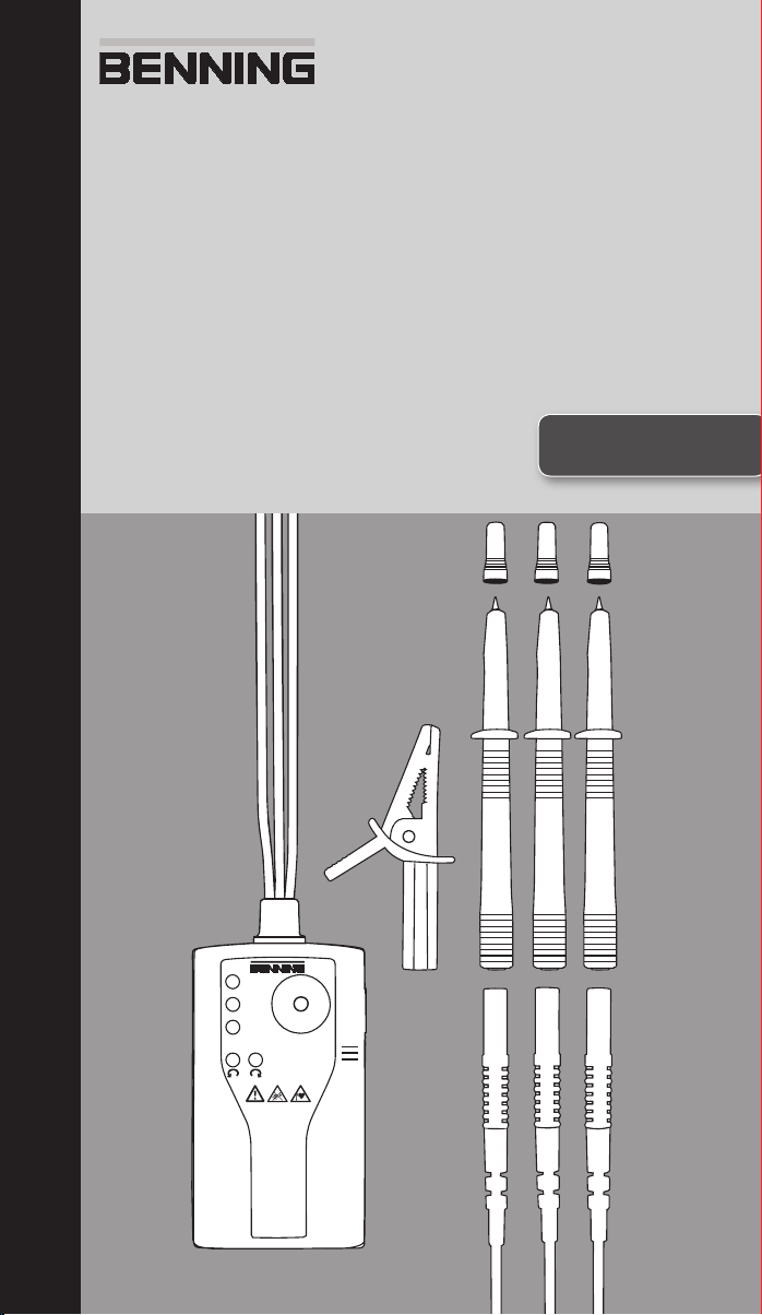
TRITEST® pro

Operating Manual
TRITEST® pro
Before using the TRITEST® pro phase sequence
indicator:
Please read the operating manual and absolutely
observe the safety instructions!
Table of contents
1. Safety instructions
2. Device description
3. Functional test
4. Phase sequence test
5. LED torch
6. Battery replacement
7. Technical data
8. General maintenance
9. Environmental protection
1. Safety instructions
- During the tests, touch the device at the insulated
test probes 9, and only and do not touch
the bare testing electrodes 8!
- Check the device for correct functioning immediately before and after using it (see section 3)! Do
not use the device, if one or more indications are
not working or if it does not seem to be ready for
operation!
- If it is assumed that safe operation is no longer
possible, the device must be switched off immediately.
- Absolutely prevent the device from getting wet
and avoid any water condensation at the device.
Moreover, the device must be protected against
contamination and damaging!
- The device must be used within the stated nominal voltage range and in electrical installations of
up to 500 V AC only!
- The device must be used only in electric circuits
of overvoltage category CAT III with max. 300 V
for phase-to-earth measurements. For measurements within measuring category III, the protruding conductive part of a testing electrode 8 of the
test probe must not be longer than 4 mm. Before
carrying out measurements within measuring category III, the enclosed attachable protective caps
marked with CAT III must be pushed onto the testing electrodes 8 for user protection purposes.
- Please observe that work on live parts and electrical components of all kinds is dangerous! Even
low voltages of 30 V AC and 60 V DC may be
dangerous to human life!
- Do not operate the device with the battery compartment being open.
- The device is designed for being used by qualified
electricians and under safe working conditions.
- Do not dismantle the device!
Attention!
The device is provided with a high-power LED torch.
Do not look directly or indirectly via reflecting surfaces
into the LED beam. An LED beam might cause irreparable damage to your eyes.
Symbols on the device:
Symbol Meaning
Attention! Please observe documentation!
This symbol indicates that the informa-
tion provided in the operating manual
must be complied with in order to avoid
risks.
Alternating voltage (AC)
Earth (voltage to earth)
This symbol shows the orientation of the
batteries for inserting them with correct
polarity.
Warning! Potentially dangerous optical
radiation!
Do not look directly into the light beam!
Danger to your retina!
Attention! Magnets might affect the correct functioning of cardiac pacemakers
and implanted defibrillators. As a user of
such medical devices, keep a sufficient
distance to the magnet.
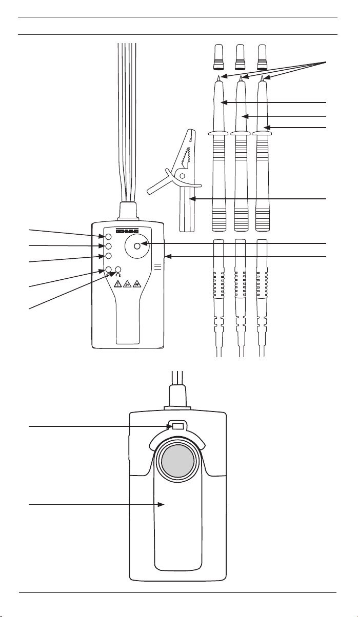
2. Device description
1
Red LED for external conductor (phase) L1
2
Red LED for external conductor (phase) L2
3
Red LED for external conductor (phase) L3
4
Red LED for counter-clockwise phase sequence
5
Green LED for clockwise phase sequence
6
High-power LED torch
7
Push-button
8
Testing electrodes with attachable protective caps
9
Test probe L1 (brown), part no.: 10112582
Test probe L2 (black), part no.: 10112581
Test probe L3 (grey), part no.: 10112584
Alligator clip, part no.: 709269
Catch of the battery compartment cover
Battery compartment cover with magnet, belt clip
and technical data
3. Functional test
- Check the device for correct functioning immediately before and after using it!
- Test the correct functioning of the LEDs
and 3 for indicating the external conductors L1,
L2 and L3 as well as the LEDs 4 and 5 of the
phase sequence indication with a familiar voltage
source, e.g. a 400 V CEE socket.
- Do not use the device, if not all functions are
working properly!
- Please replace the batteries as soon as the luminosity of the LED torch 6 decreases.
4. Phase sequence test
- Connect the connecting cables marked with L1,
L2 and L3 to the mains to be tested. For this purpose, use the test probes 9, and or the alligator clip .
- The external conductor voltages are indicated by
means of the red LEDs 1, 2 and 3.
- Depending on the connection, the red LED (4) for
"counter-clockwise phase sequence" or the green
LED 5 for "clockwise phase sequence" will be
activated.
- Interchanging the test probes on two external
conductors must result in a change of the phase
sequence.
- For each test, make sure that all three external
conductor voltages are present. Only then, the
indicated results can be analyzed!
1, 2
10/ 2014
TRITEST® pro
3
Note:
Phase sequence tests can be carried out even with
the batteries being removed or exhausted.
5. LED torch
Warning!
Potentially dangerous optical radiation!
Do not look directly or indirectly via
reflecting surfaces into the LED beam!
Danger to your retina!
- The device is provided with a high-power LED
torch 6 with can be switched on and off by pressing the push-button 7.
6. Battery replacement
- Do not apply voltage to the device when the battery compartment is open!
- The battery compartment is located on the back of
the device.
- Slightly press down the catch by means of a
screwdriver and push off the battery compartment
cover in downward direction at the same time.
- Replace the exhausted batteries by three new
ones of type AA (LR06). Make sure that the new
batteries are inserted with correct polarity!
- Push the battery compartment cover back onto
the housing until the catch locks into place with
an audible click.
Note:
The battery compartment cover is provided with an
integrated magnet and a belt clip for attachment of the
device.
7. Technical data
- Regulations: DIN EN 61010-1 and -031, IEC
61010-1 and -31, DIN EN 61557-1 and -7, IEC
61557-1 and -7, DIN EN 62471
- Nominal voltage range: 400 V to 500 V
- Measuring category: CAT III 300 V to earth
- Nominal frequency range f: 50 Hz / 60 Hz
- Current consumption: Is < 3.5 mA (500 V)
- Contamination level: 2
- Protection category: IP 40 (DIN VDE 0470-1 IEC /
EN 60529)
4 - first index: protection against access to dangerous parts and protection against solid impurities of a diameter > 1.0 mm
0 - second index: no protection against water
- Battery: 3 x 1.5 V batteries of type AA (LR06)
- Weight: approx. 250 g
- Measuring line with test handles: length of approx.
1,000 mm
- Operating temperature range: - 15 °C to + 55 °C
- Storage temperature range: - 15 °C to + 55 °C
- Relative air humidity: 20 % to 80 %
8. General maintenance
Clean the exterior of the device with a clean dry cloth.
If there is contamination or deposits in the area of the
battery or the battery housing, clean these areas as
well by means of a dry cloth.
If the device is stored for a longer period of time,
remove the batteries from the device!
9. Environmental protection
At the end of product life, dispose of the
unserviceable device as well as used batteries via appropriate collecting facilities provided in your community.
10/ 2014
TRITEST® pro
4

Benning Elektrotechnik & Elektronik GmbH & Co. KG
Phone: +49 (0) 2871 - 93 - 0 • Fax: +49 (0) 2871 - 93 - 429
www.benning.de • E-Mail: duspol@benning.de
Münsterstraße 135 - 137
D - 46397 Bocholt
 Loading...