


D
Bedienungsanleitung
Operating manual
F
Mode d‘emploi
Návod k použití zkoušečky
Οδηγίες χρήσεως
I
Istruzioni per l’uso
Gebruiksaanwijzing
Instrukcja obsługi
Инструкция по эксплуатации
индикатора напряжения
easy
®
TRITEST
D F I
A
1
2
3
4
5
6
7
B
230 VAC
PE
N L
07/2013
TRITEST® easy
D F I
C
D
07/2013
1.
3 sec.
TRITEST® easy
grün = rechts
rot = links
2.
3 sec.
D
Bedienungsanleitung Berührungsloser
Phasen-/Drehfeldprüfer TRITEST® easy
Bevor Sie den Phasen-/ Drehfeldprüfer TRITEST® easy benutzen: Lesen Sie
bitte die Bedienungsanleitung und beachten Sie un bedingt die Sicherheitshinweise!
1. Sicherheitshinweise:
- Unmittelbar vor und nach dem Benutzen den Phasen-/Drehfeldprüfer auf
Funktion prüfen! (siehe Abschnitt 3). Das Gerät darf nicht benutzt werden, wenn die Funktion einer oder mehrerer Anzeigen ausfällt oder keine
Funkti onsbereitschaft zu erkennen ist!
- Gerät beim Prüfen nur an dem roten Griff hinter der Griffbegrenzung 2
anfassen und die weiße Prüfspitze 1 nicht berühren!
- Das Gerät darf nur im angegebenen Nennspannungsbereich von
200 - 1000 V AC und in geerdeten Netzstromkreisen der Überspannungskategorie CAT III 1000 V bzw. CAT IV 600 V Leiter gegen Erde
benutzt werden.
- Der Phasen-/Drehfeldprüfer TRITEST® easy erkennt Felder von Phasen-/
Außenleiterspannungen ab ca. 200 V Wechselspannung (AC). Felder von
Gleichspannungen (DC) werden nicht erkannt!
- Beachten Sie, dass Arbeiten an spannungsführenden Teilen und Anlagen
grundsätzlich gefährlich sind. Bereits Spannungen ab 30 V AC und 60 V
DC können für den Menschen lebensgefährlich sein.
- Der Phasen-/Drehfeldprüfer TRITEST® easy ist kein Ersatz für einen zweipoligen Spannungsprüfer z. B. DUSPOL® um das Feststellen der Spannungsfreiheit zu bestimmen.
- Folgende Faktoren können die korrekte Funktionsweise der Phasen- und
Drehfeldprüfung negativ beeinflussen:
- zu großer Abstand zur prüfenden Phase (Außenleiter)
- zu starke Isolierung und Abschirmung der Phase (Außenleiter)
- Schutzkleidung und isolierende Standortgegebenheiten
- Konstruktive Unterschiede von Steckdosen/CEE-Kupplungen mit
zurückliegenden Kontakten, z.B. 63 A CEE-Kupplung
- Netzstörungen oder mangelnde Netzqualität
- Zustand der Batterien
- Gerät nicht mit geöffnetem Batterieschacht betreiben.
- Das Gerät ist für die Anwendung durch Elektrofachkräfte in Verbindung mit
sicheren Arbeitsver fahren ausgelegt.
- Das Gerät ist vor Verunreinigungen und Be schädigungen der Gehäuseoberfläche zu schützen.
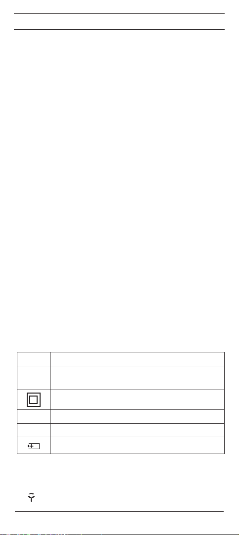
Elektrische Symbole auf dem Gerät:
Symbol Bedeutung
Achtung Dokumentation beachten!
Das Symbol gibt an, dass die Hinweise in der Bedienungsanlei-
tung zu beachten sind, um Gefahren zu vermeiden
Dieses Symbol auf dem Gerät bedeutet, dass der TRITEST®
easy schutzisoliert (Schutzklasse II) ausgeführt ist.
Wechselspannung
AC
Erde (Spannung gegen Erde)
Dieses Symbol zeigt die Ausrichtung der Batterien zum polrichtigen Einlegen an
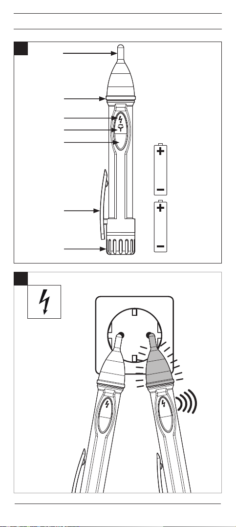
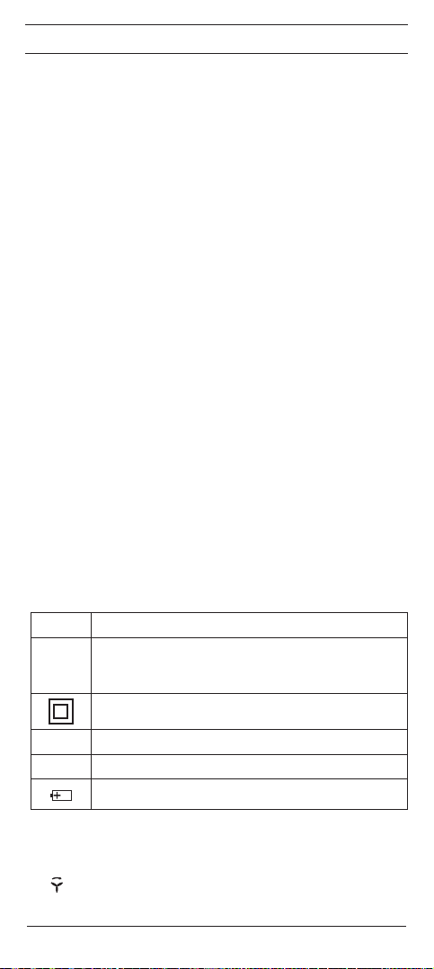
2. Gerätebeschreibung (Bild A)
1
Prüfspitze mit LED-Anzeige (grün/rot)
2
Griffbegrenzung
3
LED (gelb) für aktivierte Phasen-/Außenleiterprüfung
4
LED (rot/grün) für aktivierte Drehfeldprüfung
07/2013
TRITEST® easy
1

D
5
Ein/Aus-Taster (blau)
6
Clip
7
Batteriefachdeckel
3. Funktionsprüfung
- Unmittelbar vor und nach dem Benutzen den Phasen-/Drehfeldprüfer auf
Funktion prüfen!
- Gerät durch drücken und halten des blauen Tasters 5 einschalten. Der
Summer ertönt und die LED´s (grün/rot) der Prüfspitze 1, die gelbe LED
3
und die rote LED 4 müssen durch kurzes aufleuchten Funktion zei-
gen.
- Testen Sie die Funktion der Phasen- und Drehfeldprüfung an einer bekannten Spannungsquelle z.B. 230 V - Steckdose/5-polige CEE Steckdose.
- Der Batteriewechsel ist erforderlich, wenn sich das Gerät direkt nach dem
Einschalten wieder ausschaltet oder die LED´s 3 + 4 sowie der Signalton schwach werden.
- Verwenden Sie den TRITEST® easy nicht, wenn nicht alle Funktionen einwandfrei funktionieren!
- Der TRITEST® easy schaltet sich nach ca. 5 min selbsttätig ab (APO,
Auto-Power-Off). Ein Signalton bestätigt die Abschaltung des Gerätes.
Alternativ kann der TRITEST® easy durch drücken und halten der blauen
Taste 5 ausgeschaltet werden.
4. Funktionsweise
- Der Phasen-/Drehfeldprüfer TRITEST® easy erkennt elektrische Felder
die von Phasen-/Außenspannungen ab 200 V - 1000 V AC (45 - 65 Hz)
erzeugt werden.
- Wird ein elektrisches Feldes erfasst, leuchtet die Prüfspitze 1 rot auf und
ein Signalton ertönt. Die Blinkfrequenz der roten Prüfspitze 1 und die
Signaltonfrequenz steigt mit zunehmender Höhe des elektrischen Feldes
bzw. der anliegenden Spannung.
- Der Phasen-/Drehfeldprüfer TRITEST® easy kann benutzt werden um die
Phase (Außenleiter) einer Wechselspannung und die Drehfeldrichtung
eines Drehstromnetzes zu bestimmen.
- Für die Prüfung ist kein Stromfluss und keine elektrisch leitende Kontaktierung mit dem Anlageteil, der Steckdose oder der isolierten Leitung nötig.
- Beachten Sie, dass der TRITEST® easy nur auf ausreichend starke Felder
ab 200 V AC Phasen-/Außenleiterspannung reagiert.
Sollte der Phasen-/Drehfeldprüfer TRITEST® easy nicht reagieren, könnte der
Abstand zum spannungsführenden Anlageteil zu groß sein oder das Anlageteil
ist abgeschirmt bzw. die Isolierung ist zu dick.
5. Phasen-/Außenleiterprüfung einer Wechselspannung (Bild B)
- Gerät durch drücken und halten der blauen Taste 5 einschalten.
- Die Bereitschaft wird durch eine blinkende gelbe LED 3 angezeigt.
- Positionieren Sie die Prüfspitze 1 an die vermutete Phase (Außenleiter)
des Anlageteils.
- Das Anliegen der Phase (Außenleiter) wird über ein Signalton und das rote
Aufleuchten der Prüfspitze 1 angezeigt.
Achtung!
Beachten Sie, auch wenn der TRITEST® easy keine Phase (Außenleiter) signalisiert, kann an dem Prüfobjekt eine gefährliche Spannung anliegen. Zur
Feststellung der Spannungsfreiheit verwenden Sie bitte ausschließlich einen
zweipoligen Spannungsprüfer gemäß DIN EN 61243-3 (VDE 0682-401) z.B.
einen DUSPOL® - Spannungsprüfer.
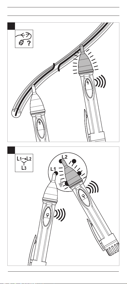
Hinweis zur Prüfung isolierter Leitungen: (Bild C)
Um Unterbrechungen an spannungsführenden Leitungen (z.B. Kabelbruch in
Kabeltrommel oder defekte Lampen in Lichterketten) zu lokalisieren, führen Sie
die Prüfspitze 1 entlang der isolierten Leitung von der Einspeisestelle (Phase)
Richtung dem anderen Lei tungsende. Bei der Prüfung einer Kabeltrommel ist
zu beachten, dass der Schutzkontaktstecker um 180 ° gedreht werden muss
um beide Leitungen an die Phase (Außenleiter) einer Schutzkontaktsteckdose
anzuschließen.
07/2013
TRITEST® easy
2
D
6. Drehfeldprüfung eines Drehstromnetzes (Bild D)
- Die Drehfeldprüfung erfordert stets eine Gegenkontrolle bei der sich die
Drehfolge ändern muss.
- Gerät durch drücken und halten der blauen Taste 5 einschalten. Die
gelbe LED 3 muss blinken.
- Blaue Taste 5 erneut betätigen um die Drehfeldprüfung zu aktivieren. Die
LED 4 muss rot blinken.
- Positionieren Sie die Prüfspitze 1 für ca. 3 Sek. an die vermuteten Phase
(Außenleiter) L1. Ein Signalton ertönt und die LED 4 blinkt rot.
- Sobald die LED 4 grün aufleuchtet kontaktieren Sie innerhalb von 2 Sek.
die Prüfspitze 1 mit der vermuteten Phase (Außenleiter) L2. Ein Signalton ertönt und die LED 4 blinkt grün.
- Sobald die LED 4 erlischt und der Signalton 3 x ertönt wird die Drehfolge
über die Prüfspitze angezeigt:
- Prüfspitze grün leuchtend: Rechtsdrehfolge (Phase 1 vor Phase 2)
- Prüfspitze rot leuchtend: Linksdrehfolge (Phase 2 vor Phase 1)
- Prüfspitze grün blinkend: gleiche Phase (Phase 1 = Phase 2)
- Prüfspitze grün/rot blinkend: Drehfolge konnte nicht ermittelt werden.
Hinweis:
Halten Sie das Gerät bei den Messungen stets ruhig, ohne zu wackeln.
Netzstörungen oder mangelnde Netzqualität können die korrekte Funktions-
weise negativ beeinussen.
7. Batteriewechsel (Bild A)
- Gerät bei offenem Batteriefach nicht an Spannung legen!
- Den Batteriefachdeckel 7 vom Gerät schrauben und die verbrauchten
Batterien aus dem Gerät entnehmen.
- Neue Batterien des Typs Micro (LR03/AAA) polrichtig (Pluspol voran) in
das Gerät stecken.
- Batteriefachdeckel 7 auf das Gehäuse schrauben.
8. Technische Daten:
- Vorschrift: DIN EN 61010-1, DIN EN 61326
- Nennspannungs-/Frequenzbereichbereich: 200 V - 1.000 V AC/45 - 65 Hz
-
Überspannungskategorie: CAT III 1.000 V/CAT IV 600 V
- Verschmutzungsgrad: 2
- Schutzart: IP 53 (DIN EN 60529), Schutz gegen Staub und Sprühwasser
- Automatsche Abschaltung: nach ca. 5 Minuten
- Betriebstemperaturbereich: - 10 °C bis + 40 °C, Luftfeuchte ≤ 75%,
40 °C bis + 50 °C, Luftfeuchte ≤ 45%,
- Lagertemperaturbereich:
- 20 °C bis + 60 °C, Luftfeuchte ≤ 80% (ohne Batterien)
- Geräteabmessungen (L x B x H): ca. 153 x 20 x 25 mm
- Gewicht: ca. 40 g (inkl. Batterien)
- Batterietyp: 2 x Micro, LR03/AAA (1,5 V)
Der Phasen-/Drehfeldprüfer TRITEST® easy ist bei leerer Batterie nicht funktionsfähig!
9. Allgemeine Wartung
Reinigen Sie das Gehäuse äußerlich mit einem sauberen tro ckenen Tuch.
Falls Verunreinigungen oder Ablagerungen im Bereich der Batterie oder des
Batteriegehäuses vorhanden sind, reinigen Sie auch diese mit einem trockenen Tuch. Entfernen Sie bei längerer Lagerung die Batterien aus dem Gerät!
10. Umweltschutz
Bitte führen Sie verbrauchte Batterien und das Gerät am Ende seiner
Lebensdauer den zur Verfügung ste hen den Rückgabe- und Sammelsystemen zu.
07/2013
TRITEST® easy
3

D
11. Produktsupport
Für weiterführende Auskünfte stehen Ihnen die Fachleute des Lieferanten bzw.
des Herstellers zur Verfügung.
BENNING Elektrotechnik und Elektronik GmbH & Co. KG
Service Center
Robert-Bosch-Str. 20
D - 46397 Bocholt
Service-Hotline: +49 (0) 2871 / 93 – 555
Zentrale: +49 (0) 2871 / 93 - 0
Fax: +49 (0) 2871 / 93 - 429
Internet: www.benning.de • E-Mail: duspol@benning.de
07/2013
TRITEST® easy
4
Operating Manual for TRITEST® easy
Non-Contact Phase/Phase Sequence Tester
Before using the TRITEST® easy phase/phase sequence tester: Please read
the operating manual and absolutely observe the safety instructions!
1. Safety instructions
- Check the phase/phase sequence tester for correct functioning immediately before and after using it (see chapter 3)! Do not use the tester, if one
or more indications are not working or if it does not seem to be ready for
operation!
- During the tests, touch the tester at the red handle behind the grip limit 2
only and do not touch the white probe tip 1!
- The tester must be used only within the stated nominal voltage range from
200 to 1,000 V AC and in earthed mains supply circuits of overvoltage category CAT III 1,000 V or CAT IV 600 V for phase-to-earth measurements.
- The TRITEST® easy phase/phase sequence tester detects fields of phase/
external conductor voltages from approx. 200 V alternating voltage (AC)
on. Direct voltage (DC) fields will not be detected!
- Please observe that work on live parts and electrical components of all
kinds is dangerous! Even low voltages of 30 V AC and 60 V DC may be
dangerous to human life!
- The TRITEST® easy phase/phase sequence tester is not a substitute for
a two-pole voltage tester such as e.g. the DUSPOL® to determine the absence of voltage.
- The following factors might affect the correct functioning of the phase test
and phase sequence test:
- excessive distance to the phase (external conductor) to be tested
- excessive insulation and shielding of the phase (external conductor)
- protective clothing and insulating conditions on site
- constructional differences of sockets / CEE couplings with recessed
contacts, e.g. 63 A CEE coupling
- mains failures or lacking mains quality
- battery condition
- Do not operate the device with the battery compartment being open.
- The tester is designed for being used by qualified electricians and under
safe working conditions.
- The tester must be protected against contamination and damaging of the
housing surface.
Electrical symbols on the device:
Symbol Meaning
Attention! Please observe documentation!
This symbol indicates that the information provided in the operat-
ing manual must be complied with in order to avoid risks.
This symbol on the TRITEST® easy indicates that the tester is
equipped with protective insulation (protection class II).
Alternating voltage
AC
Earth (voltage to earth)
This symbol shows the orientation of the batteries for inserting
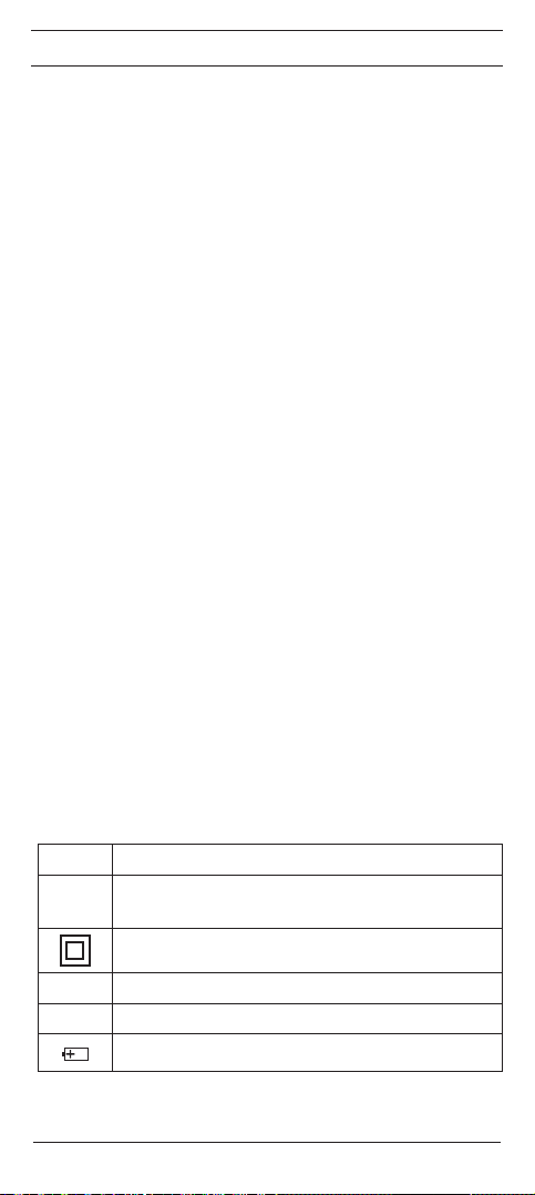
2. Device description (figure A)
1
2
3
4
5
07/2013
them with correct polarity.
Probe tip with LED indication (green/red)
Grip limit
LED (yellow) for activated phase/external conductor test
LED (red/green) for activated phase sequence test
ON/OFF push-button (blue)
TRITEST® easy
5

6
Clip
7
Battery compartment cover
3. Functional test
- Check the phase/phase sequence tester for correct functioning immediately before and after using it!
- Press and hold the blue push-button 5 to switch the tester on. The buzzer
sounds and the LEDs (green/red) of the probe tip 1, the yellow LED 3
and the red LED 4 must be functioning (must light up briefly).
- Test the phase/phase sequence tester for correct functioning with a familiar voltage source, e.g. a 230 V socket/5-pin CEE socket.
- Replace the batteries, if the tester switches off directly after being switched
on or if the LEDs 3 and 4 as well as the acoustic signal are getting weak.
- Do not use the TRITEST® easy, if not all functions are working properly!
The TRITEST® easy is switched off automatically after approx. 5 minutes
(APO, Auto-Power-Off). An acoustic signal confirms that the tester has
switched off. Alternatively, press and hold the blue push-button 5 to
switch the TRITEST® easy off.
4. How the tester works
- The TRITEST® easy phase/phase sequence tester detects electric fields
generated by phase/external conductor voltages from 200 V to 1,000 V AC
(45 to 65 Hz) on.
- If an electric field is detected, the probe tip 1 lights up in red color and an
acoustic signal is emitted. The flashing frequency of the red probe tip 1 as
well as the frequency of the acoustic signal increase with the electric field
or the voltage applied increasing as well.
- The TRITEST® easy phase/phase sequence tester can be used to determine the phase (external conductor) of an AC voltage as well as the phase
sequence of a three-phase mains.
- The test does not require any current flow and no electrically conductive
contact with the system part, socket or insulated line.
- Please observe that the TRITEST® easy only responds to sufficiently
strong fields with a phase/external conductor voltage from 200 V AC on.
If the TRITEST® easy phase/phase sequence tester does not react, the distance to the live system part might be too large, the system part might be
shielded or the insulation might be too thick.
5. Phase/external conductor test of an AC voltage (gure B)
- Press and hold the blue push-button 5 to switch the tester on.
- The yellow LED 3 flashes to show that the tester is ready for operation.
- Place the probe tip 1 onto the assumed phase (external conductor) of the
system part.
- If the phase (external conductor) has been detected, this is confirmed by
an acoustic signal and by the probe tip 1 lighting up in red color.
Attention!
Please observe that even if the TRITEST® easy does not indicate a phase (external conductor), a dangerous voltage may be applied to the test object. For
determining the absence of voltage, only use a two-pole voltage tester complying with the DIN EN 61243-3 (VDE 0682-401) standard, e.g. a DUSPOL®
voltage tester.
Note on testing insulated lines (gure C):
To localize interruptions of live lines (e.g. a cable break in a cable reel or defective lamps in a chain of lights), pass the probe tip 1 along the insulated line
from the feeding point (phase) in direction of the other end of the line.
For testing a cable reel, make sure to turn the shock-proof plug by 180° in order
to connect both lines to the phase (external conductor) of a shock-proof socket.
6. Phase sequence test of a three-phase mains (gure D)
- The phase sequence test always requires a countercheck during which the
phase sequence must change.
- Press and hold the blue push-button 5 to switch the tester on. The yellow
LED 3 must flash.
- Press the blue push-button 5 again to activate the phase sequence test.
The LED 4 must flash in red color.
- Place the probe tip 1 onto the assumed phase (external conductor) L1 for
07/2013
TRITEST® easy
6
approx. 3 seconds. An acoustic signal is emitted and the LED 4 flashes in
red color.
- As soon as the LED 4 lights up in green color, connect the probe tip
1
with the assumed phase (external conductor) L2 within 2 seconds. An
acoustic signal is emitted and the LED 4 flashes in green color.
- As soon as the LED 4 goes out and the acoustic signal is emitted three
times, the phase sequence is indicated via the probe tip.
- probe tip lights in green color: clockwise phase sequence (phase 1 before
phase 2)
- probe tip lights in red color: counter-clockwise phase sequence (phase 2
before phase 1)
- probe tip ashes in green color: equal phase (phase 1 = phase 2)
- probe tip flashes in green/red color: phase sequence could not be determined
Note:
Always hold the device steady during the measurements without wobbling.
Mains failures or a lacking mains quality might affect the correct functioning
of the device.
7. Battery replacement (gure A)
- Do not apply voltage to the device when the battery compartment is open!
- Remove the battery compartment cover 7 from the tester by loosening
the screws and remove the used batteries.
- Insert new micro batteries (LR03/AAA) into the tester observing correct
polarity (positive pole first).
- Place the battery compartment cover 7 back onto the tester and tighten the
screws.
8. Technical data
- regulation: DIN EN 61010-1, DIN EN 61326
- nominal voltage/frequency range: 200 V to 1,000 V AC/45 to 65 Hz
- overvoltage category: CAT III 1,000 V/CAT IV 600 V
- contamination level: 2
- protection category: IP 53 (DIN EN 60529), protection against dust and
water spray
- automatic switch-off: after approx. 5 minutes
- operating temperature range: - 10 °C to + 40 °C, air humidity ≤ 75%, 40 °C
to + 50 °C, air humidity ≤ 45 %,
- storage temperature range: - 20 °C to + 60 °C, air humidity ≤ 80% (without
batteries)
- dimensions of the tester (L x W x H): approx. 153 x 20 x 25 mm
- weight: approx. 40 g (incl. batteries)
- battery type: 2 x micro, LR03/AAA (1.5 V)
The TRITEST® easy phase/phase sequence tester does not work with the battery being exhausted!
9. General maintenance
Clean the exterior of the device with a clean dry cloth.
If there is contamination or deposits in the area of the battery or the battery
housing, clean these areas as well by means of a dry cloth. If the device is
stored for a longer period of time, remove the batteries from the device!
10. Environmental protection
At the end of product life, dispose of the unserviceable device as well
as used batteries via appropriate collecting facilities provided in your
community.
07/2013
TRITEST® easy
7

11. Product support
Please contact the expert personnel of the supplier or manufacturer for further
information.
BENNING Elektrotechnik und Elektronik GmbH & Co. KG
Service Center
Robert-Bosch-Str. 20
D - 46397 Bocholt
Service hotline: +49 (0) 2871/93 - 555
Head ofce: +49 (0) 2871/93 - 0
Fax: +49 (0) 2871/93 - 429
Internet: www.benning.de • E-mail: duspol@benning.de
07/2013
TRITEST® easy
8
F
Mode d‘emploi du détecteur de
phase/d‘ordre de phases sans
contact TRITEST® easy
Avant d‘utiliser le détecteur de phase/d‘ordre de phases TRITEST® easy: Lisez
le mode d‘emploi et tenez impérativement compte des consignes de sécurité !
1. Consignes de sécurité :
- Contrôlez toujours le bon fonctionnement du détecteur de phase/d‘ordre
de phases immédiatement avant et après de l‘utiliser ( voir paragraphe 3 ) !
Le détecteur ne doit pas être utilisé dès lors qu‘une ou plusieurs affichages
ne fonctionnent plus ou dès lors l‘appareil n‘est plus opérationnel !
- Lors du contrôle, ne prenez le détecteur que par la poignée rouge derrière
la surface de prise limitée 2 et ne touchez pas la pointe d‘essai blanche
1
!
- Le détecteur ne doit être utilisé que dans la plage de tension nominale
spécifiée de 200 à 1.000 V AC et dans les circuits électriques de secteur
mis à la terre de la catégorie de surtension CAT III 1.000 V ou CAT IV avec
des conducteurs de 600 V par rapport à la terre.
- Le détecteur de phase/d‘ordre de phases TRITEST® easy sert à détecter
des champs des tensions de phase/tensions composées à partir de 200 V
AC environ. Les champs des tensions continues ( DC ) ne sont pas détectés !
- Tenez compte du fait qu‘il est toujours dangereux de travailler sur les composants et sur les installations sous tension. Déjà les tensions à partir de
30 V AC et 60 V DC peuvent être mortelles !
- Le détecteur de phase/d‘ordre de phases TRITEST® easy ne sert pas
de substitut d‘un contrôleur de tension bipolaire comme par exemple le
DUSPOL® afin de déterminer l‘absence de tension.
- Les facteurs suivants pourraient affecter le bon fonctionnement du test de
phase et du test d’ordre de phases :
-
une distance trop grande à la phase ( conducteur extérieur ) à contrôler
- une isolation trop forte ou un blindage trop fort de la phase ( conduc-
teur extérieur )
- vêtements protecteurs et conditions isolantes sur site
-
différences quant à la construction des prises de courant / coupleurs
CEE avec des contacts en retrait comme par ex. un coupleur CEE 63 A
- pannes de secteur ou qualité insuffisante du secteur
- état des piles
- N‘utilisez jamais l‘appareil si le compartiment à piles est ouvert.
- Le détecteur est conçu afin d‘être utilisé par des électrotechniciens en
combinaison avec des procédés de travail sûrs.
- Protégez le détecteur contre les impuretés ainsi que contre l‘endommagement de la surface du boîtier.
Symboles électriques sur l‘appareil :
Symbole Signication
Attention ! Tenir compte de la documentation !
Ce symbole indique qu’il faut tenir compte des instructions conte-
nues dans ce mode d’emploi an d’éviter tout risque.
Ce symbole sur l‘appareil signie que le TRITEST® easy est doté
d‘une isolation double ( classe de protection II ).
Tension alternative
AC
Terre (tension par rapport à la terre)
Ce symbole montre l‘orientation des piles an de les insérer en
respectant la polarité correcte.
2. Description de l‘appareil ( gure A )
1
Pointe d‘essai avec indication par LED ( verte/rouge )
07/2013
TRITEST® easy
9
 Loading...