

Page 1

Tebevert III 25kVA
120VDC Inverter System
028-0009-006 Rev. C
Operations and Maintenance Manual
Benning Power Electronics
1220 Presidential Drive Suite 100
Richardson, TX 75081 USA
www.benning.us
800.910.3601
This manual contains important
safety instructions that should be
followed during installation and
maintenance of the Power
System.
Page 2

Page 3

TABLE OF CONTENTS
0 IMPORTANT INFORMATION .................................................................................................................. i
0.1 VERSION .............................................................................................................................. i
0.1 PASSWORD .......................................................................................................................... ii
0.1 DATA SHEET ....................................................................................................................... iii
0.2 PREFACE ............................................................................................................................. 1
1 SAFETY NOTES AND MARKINGS ........................................................................................ 3
2 GENERAL ............................................................................................................................ 6
3 THE COMPONENTS OF THE TYPICAL INVERTER SYSTEM .................................................. 6
3.1 PSJ TYPE EQUIPMENT CABINET .......................................................................................... 7
3.2 INVERTER SLOTS ............................................................................................................... 10
3.3 SBS SLOT .......................................................................................................................... 12
3.4 MANUAL MAINTENCE BY-PASS SWITCH .............................................................................. 12
3.5 INVERTER .......................................................................................................................... 15
3.5.1 DESIGN OF THE UNIT ..................................................................................................... 15
3.5.2 TERMINALS AND OPERATING UNITS ............................................................................... 17
3.5.3 SIGNALLING ................................................................................................................... 19
3.6 ELECTRONIC SWITCH-OVER SBS UNIT ............................................................................... 21
3.6.1 DESIGN OF THE UNIT ..................................................................................................... 22
3.6.2 TERMINALS AND OPERATING ELEMENTS......................................................................... 23
3.6.3 SIGNALLING ................................................................................................................... 25
3.7 ACD DISTRIBUTIN PANEL ................................................................................................... 26
3.7.1 NA STYLE SNAP-IN BREAKER PANEL ............................................................................ 26
3.7.2 DIN RAIL STYLE BREAKER PANEL ................................................................................... 27
3.8 TECHNICCAL DATA .................................................................................................................. 27
4 INSTALLATION AND COMMISSIONING ........................................................................... 28
4.1 INVERTER SETTINGS ......................................................................................................... 29
4.2 SETTINGS OF THE ELECTRONIC SWITCH –OVE R/ SB S UNI T ................................................. 30
4.3 PANEL WRITING ................................................................................................................ 32
4.3.1 DC CABLE REQUIREMENTS FOR 25kVA, 120, INDIVIDUAL DC INPUT (DIN RAIL TERMINAL
BLOCK) ..................................................................................................................................... 34
4.3.2 DC CABLE REQUIREMENTS FOR 25kVA, 120VDC, BULK DC INPUT SYSTEM ....................... 34
Page 4

4.3.3 AC CABLE REQUIREMENTS FOR 25kVA, 120 VAC AC INPUT RATI NGS. ............................. 35
4.3.4 AC CABLE REQUIR EMENTS FOR 25kVA, 120/240 VAC INPUT SYSTEM . .............................. 35
4.3.5 AC CABLE REQUIREMENTS FOR 25kVA, 208 VAC INPUT SYSTEM.. .................................... 35
4.3.6 AC CABLE REQUIREMENTS FOR 25kVA, 220 VAC INPUT SYSTEM ..................................... 36
4.3.7 AC CABLE REQUIREMENTS FOR 25kVA, 240 VAC INPUT SYSTEM ..................................... 36
4.3.8 AC CABLE REQUIREMENTS FOR 25kVA, 480 VAC INPUT SYSTEM ...................................... 36
4.3.9
TORQUE TABLE FOR ALL TERMINATIONS
4.4 INSTALLATION OF THE UNITS ............................................................................................ 60
4.4.1 INSTALLATION OF THE STATIC BY-PASS SWITCH (SBS) .................................................. 39
4.4.2 INSTALLATION OF THE INVERTERS ................................................................................ 40
4.5 SWITCHING ON THE INVERTER SYSTEM ............................................................................. 40
5 PERFORMANCE TESTING ................................................................................................. 42
5.1 PRELIMINARIES TO PERFORMANCE TEST ........................................................................... 42
5.2 TEST EQUIPMENT .............................................................................................................. 43
5.3 TEST OF THE INVERTERS ................................................................................................... 43
5.3.1 INVERTER TEST ACTIVITIES ........................................................................................... 43
5.4 TEST OF THE S BS UNIT ...................................................................................................... 45
5.4.1 SBS TEST ACTIVITIES .................................................................................................... 46
5.5 FINAL STEPS ...................................................................................................................... 47
6 MAINTENANCE ................................................................................................................. 47
........................................................................ 37
6.1 USE OF THE MANUAL BY-PASS SWITCH .............................................................................. 47
6.2 EXCHANGE OF UNITS ......................................................................................................... 50
6.3 UPGRADING THE SYSTEM .................................................................................................. 51
7 DESCRIPTION OF FUNCTION ........................................................................................... 51
7.1 TOTAL SYSTE M .................................................................................................................. 51
7.2 INVERTER .......................................................................................................................... 52
7.2.1 MONITORING THE INPUT VOLTAGE ............................................................................... 52
7.2.2 MONITORING THE OUTPUT VOLTAGE ............................................................................. 54
7.2.3 MONITORING THE TEMPERATURE .................................................................................. 54
7.2.4 OVERLOAD BEHAVIOR .................................................................................................... 54
7.2.5 SHORT-CIRCUIT BEHAVIOR ............................................................................................ 55
7.3 ELECTRONIC SWITCHING/SBS UNIT ................................................................................... 55
Page 5

Revision
Date
Originator
Approver
C
07.08.11
A.Waggott/J.Almond
D.Almond
VERSION:
A 06.01.08 C.Tumey D.Almond
B 03.12.10 C.Tumey E.McDonald
Publication Document: Version 1.1
Copyright © 2007 Benning Power El ectronics
Proprietary Information: This ma nual contains proprietary information which is
protected by copyright law. All r ights are reserved. No part of this manual may be
photocopied, reproduced, or translated to another language without prior written
consent of Benning Power Electronics. Specifications in this manual are subject to
change without notice.
Page 6

ii
PASSWORD:
Password Level 1: PW 1
Password Level 2: PW 2
Password Level 3: PW 3
Password Level 4: PW 4
NOTE:
PUT A SPACE BETWEEN PW AND THE
NUMBER
Page 7
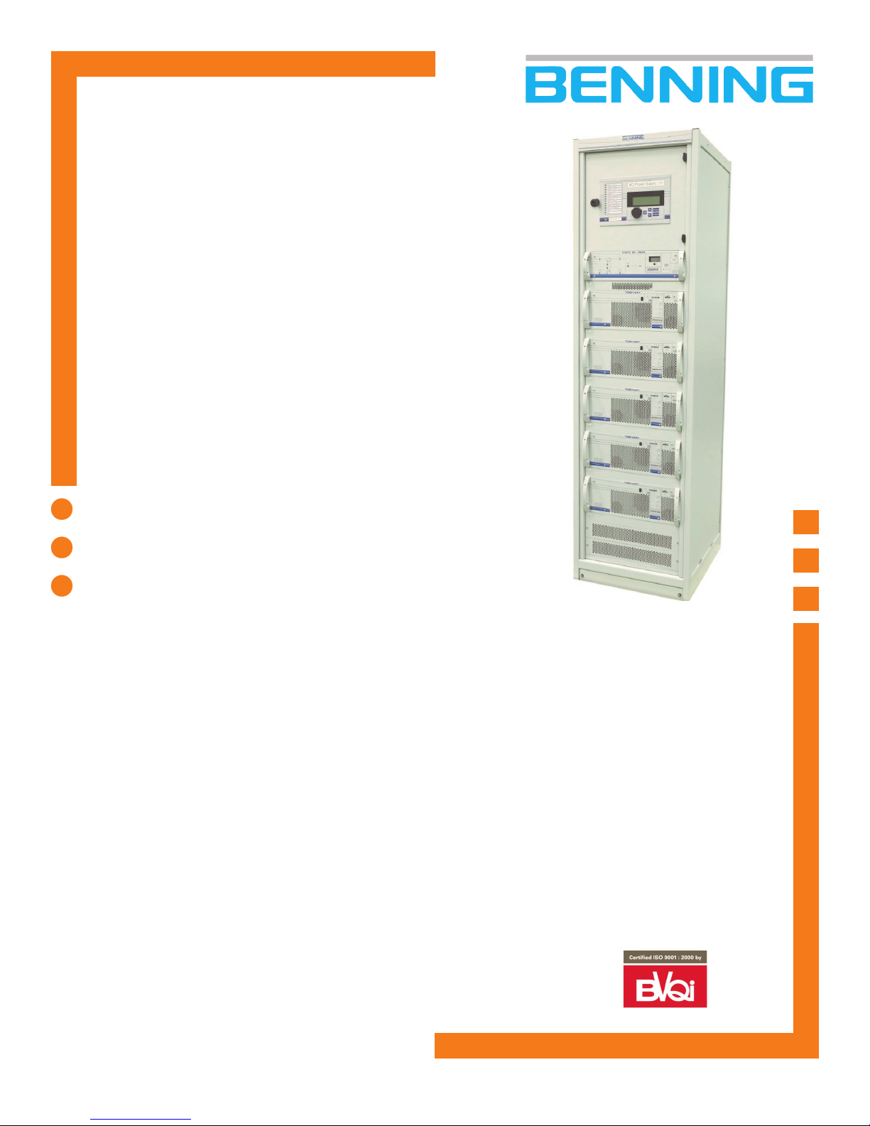
TEBEVERT III MODULAR
5-25 kVA INVERTER SYSTEM
The TEBEVERT III Modular Inverter System is designed
to address the critical AC powering requirements of
Industrial and Utility applications. The TEBEVERT III
Modular Inverter System can be scaled in 5 kVA
increments up to 25 kVA (non-redundant). Unlike
conventional stand alone inverters, these parallel
operating inverters can also be scaled to operate with
N+1 redundancy. N+1 redundancy insures optimal
availability for your critical load applications. If an
inverter failure should ever occur, the faulty inverter
module will automatically be removed from the output
bus before a disruption in the output is seen by the
critical load. In this mode of operation, a failure of one
inverter will not effect the operation of your critical load.
Since all units are designed for “hot swap” replacement,
a faulty module can easily be unplugged and replaced
to maintain power to your critical load.
Key Features
Hot Swap 5 kVA Inverter Modules
Hot Swap Static Switch Module
Supports High Inrush Current Loads
High Efficiency Operation, Lowers Operating Costs
Low Distortion Output Voltage
Integrated Maintenance Bypass Switch
Meets EN 55022 Class B Requirements
Automatic Master-Slave Operation
Up to Five Inverter Modules Can Be Paralleled As Load
Increases
No Single Points Of Failure
User Friendly Display Of Operating Mode
Optional—Seismic Zone 4 Certified
Optional—Internal AC Load Distribution Circuit Breakers
120VDC Tebevert III
System
Tebevert III_120 (R1_07) © Benning Power Electronics 2007
Specifications are subject to change without notice
Page 8

Technical Specifications
60HZ Models
Output Capacity 5 - 25.0 KVA
Maximum Number of Modules The inverter cabinet supports a maximum of 5 inverter modules
Nominal Bypass AC Input 120 VAC 208, 220, 240, 480VAC
# of Bypass AC Phases 1 2
Bypass AC Input Wiring L, N, PE L1, L2, PE
Nominal DC Input 120VDC
DC Input Range -15%, +20%
Reflected DC Ripple, 120VDC < 2mV reverse smoothing
Nominal AC Output Voltage 120VAC 120VAC
Optional AC Output Voltage 120/240VAC 120/240VAC
Output Voltage Regulation +/- 5% for all combinations of line, load and temperature
Output Power Factor 0.7 lagging to 0.8 leading
Output Voltage Waveform PWM sine-wave
Output Crest Factor 2:8:1
Output Voltage Distortion < 3.5% @ 100% rated linear load
Output Overcurrent Protection Electronic current limiting
Overload Rating (Inverters) 200% for approx. 75 cycles (1.25 seconds)
Overload Rating (Static Bypass) 500% for 100ms
System Operating Efficiency > 89% (typical)
Frequency Stability +/- 0.1% free running, +/- 3% when AC present
Module Capacity 5.0kVA/4.0kW
Static Switch Transfer Time < 2ms
Cooling Temperature controlled fans
Maintenance Bypass Switch Standard make-before-break mechanically interlocked switch provided on all models
Remote Alarming (1) Form-C Summary Alarm, Optional Relay Card (8 Alarms)
LED indicators (Inverter Modules) Output present, fault, overload, AC synchronized, parallel operation
LED indicators (Static Bypass Switch) Power flow diagram, normal, fault, ac present, dc present, overload, load on bypass, load on
Metering (4) segment LCD display switchable between output voltage and current
Cabinet Dimensions (H x W x D) 84” (2134 mm) x 23.6” (600 mm) x 23.6” (600 mm)
Radio Interference EN 55022, class B
Altitude 6000 ft (1800 m), 13, 000 ft. (4000 m) at 30°C
Operating Temperature -5 to +40° C
Operating Humidity 0-95% non-condensing
Module Data 5.0kVA
Power Rating 5000VA/4000W
Nominal Input Current 120 VDC 38.0A
Maximum Input Current 120VDC 44A
Output Current NOM 120VAC 41.6A
< 5% RMS
inverter
Benning Power Electronics, Inc. Toll Free: 800.910.3601
11120 Grader St . Dallas . TX 75238 Outside the US: 214.553.1444
E-Mail: sales@benning.us Fax: 214.553.1355
WEB:www.benning.us
Tebevert III_120 (R1_07) © Benning Power Electronics 2007
Specifications are subject to change without notice
Page 9

TEBEVERT III INVERTER SYSTEM (120 VDC)
PREFACE
Congratulations and thank you for purchasing a Benning TEBEVERT III
Inverter System!
We at Benning are committed to supporting the needs of our customers by supplying
the customer with the proper information and documentation needed to properly install
and operate the unit purchased.
Important:
This avoids:
Danger during installation and operation.
Danger to operating personnel.
Downtime.
Increases the reliability and lifespan of the system.
This manual explains all the necessary information to unpack, install, and operate the
Benning BLI Inverter System and related components. Refer questions outside the
scope of this manual to our Customer Service Department.
Customer Service:
It is imperative that all the information be observed.
We are committed to excellence in dependabi li ty and customer satisfaction. If you have
any questions or problems, please contact the Customer Service Department at:
1.800.910.3601 or 214.553. 1444 for more information.
Please read all instructions before installing or operating the equipment and save these
manuals for future reference.
07.11.2011 1 028-0009-006
Page 10

TEBEVERT III INVERTER SYSTEM (120 VDC)
Switched-Mode Modular
Series TEBEVERT
(HOT-PLUG-Version)
Inverter System
Model:
5.0kVA-25.0kVA (120VDC Input, 120 VAC Output
Modules)
07.11.2011 2 028-0009-006
Page 11

TEBEVERT III INVERTER SYSTEM (120 VDC)
1 SAFETY NOTES AND MARKINGS
This operating manual conta i ns im portant information for the installation,
operation, and maintenance of the inverter system. This manual must be retained
and observed at all times!
Explanation of the symbols used:
avoid danger to persons!
Indicates instructions which must b e followed to avoid
Indicates safety instructions which m ust be followed to
material damage!
All specifications in these operating instructions must be
observed at all times!
Index of abbreviations:
A Amps
AC Alternating Current
DC Direct C ur r ent
I Current
LVD Low Voltage Detector
CB Circuit Breaker
G Ground
L Line
N Neutral
SNMP Simple Network Management Protocol
V Volts
W Watts
07.11.2011 3 028-0009-006
Page 12

TEBEVERT III INVERTER SYSTEM (120 VDC)
Further symbols, diagrams and pictures are explained at the appropriate
places within this operating manual.
Explanation of the abbreviations a nd definitions used:
SBS Static By-Pass Switch (SBS)
DVA Digital volt-ammeter
Mains Commercial AC input power source
By-pass Input Commercial AC Mains voltage providing an alternative AC
source to the connected load equipment . The By-pass
input is used by either the manual maintenance by-pass
or the SBS for back-up support in the event of an
inverter system failure.
07.11.2011 4 028-0009-006
Page 13

TEBEVERT III INVERTER SYSTEM (120 VDC)
The inverter system is an electrical unit with dangerous
voltage and current levels. For t hi s reason, the following
safety instructions must be o bserved.
1. Installation, operation, maintenance, and repair should be carried out in
strict accordance with the instructions in this document.
2. Ensure that only fully trained and qualified personnel have access to the
system. Only qualified and authorized personnel should be able to open
the units.
3. Even when the unit is completely switched off, some of i ts interior
components remain live as long as they are connected to the mains
supply or the battery.
4. Installed capacitors may be charged even w hen the system is
disconnected. These must be correctly discharged by a qualified
technician before the connectio ns or terminals are touched.
5. When working at the unit, use properly insulated tools at all times which
are suitable for the levels of voltage concerned.
6. All persons working with the unit must be familia r with the first-aid
techniques to be adopted in cases of accidents involving electricity.
7. The regulations of the local power supply companies and all other
applicable safety regulations must be observed at all times.
07.11.2011 5 028-0009-006
Page 14
TEBEVERT III INVERTER SYSTEM (120 VDC)
Warning!
2 GENERAL
The TEBEVERT III family of modular inverter systems consists of: modular
hot-plug, inverters, and an electronic static by-pass switch (SBS). All
electrical connections are a utomatically disconnected or connected when
the modules are pulled out of or pushed i nto the system cabinet. This may
take place during normal operation without interruption in power to the
connected load equipment. Thi s design provides an uninterrupted supply
of AC current and satisfies the highest requir ements with respect to the
expansion of the system, ease of maintenance and operating safety.
The TEBEVERT III is available for DC voltages of 120VDC. Each inverter
module is available in 5.0kVA/4.0kW. Parallel operation of maximum of
five (5) inverter modules provides a maximum system rating of
25.0kVA/20kW. Th e output voltage is 120VAC or 120/240VAC and can be
adjusted to 50Hz or 60Hz according to the application.
Several inverter systems may not be operated in parallel.
This may lead to the destruction of the inverter systems.
3 THE COMPONENTS OF THE TYPICAL INVERTER
SYSTEM
The design and arrangement of the components of the inverter system are
generally standardized.
The standard components are:
• (1) PSJ type equipment shelf
• 5 positions for the inverters
• (1– 5) inverter mod ul es
• (1) position for the static by-pass switch (SBS)
• (1) ma nual maintenance by-pass switch
07.11.2011 6 028-0009-006
Page 15

TEBEVERT III INVERTER SYSTEM (120 VDC)
The input of the terminals and distribution positions within the cabinet
depend on the supplied configuration. Refer to the equipment elevation
drawing for specific terminal siz es and placement.
The inverter’s static by-pass switch is only o pera tional when properly
installed into its corresponding position.
3.1 PSJ TYPE EQUIPMENT CABINET
The Benning TEBEVERT III system is built and supp li ed into a 19” PSJ
type, fully enclosed, floor sta nding cabinet (23.6” X 23.6” X 7’0” outside
overall dimension). Cabinets are available for New Equipment building
Standards (NEBS) and non-NEBS applications. Deep cabinets (600mm x
800mm or 23.6” x 31.5” x 7’0”) are available for special applications i.e.
raised floor, etc. consult with Benning at time of o r der.
07.11.2011 7 028-0009-006
Page 16

TEBEVERT III INVERTER SYSTEM (120 VDC)
Input Terminals and distribution
position
(depending on the application)
Static By-Pass Switch (SBS) shelf
Inverter module shelf 5
(A5)
Inverter module shelf 4
(A4)
Inverter module shelf 3
(A3)
Inverter module shelf 2
(A2)
Inverter module shelf 1
(A1)
Transformers.
07.11.2011 8 028-0009-006
Fig. 1: Typical design of top feed cabinet
Page 17

TEBEVERT III INVERTER SYSTEM (120 VDC)
0
12
Manual by-pass switc h (Q10)
SBS module (A6)
Inverter Module 5 ( A5 )
Inverter Module 4 ( A4 )
Inverter Module 3 ( A3 )
Inverter Module 2 ( A2 )
Inverter Module 1 ( A1 )
Figure 2: Typic al Inverter System (shown
with inverter modules, static by-pass)
07.11.2011 9 028-0009-006
Page 18

TEBEVERT III INVERTER SYSTEM (120 VDC)
Figure 3
TYPICAL INPUT/OUTPUT TERMINALS FOR AN
INDIVIDUAL FEED CONFIGURATION
TYPICAL SNMP OPTION
07.11.2011 10 028-0009-006
Figure 4
Page 19

TEBEVERT III INVERTER SYSTEM (120 VDC)
3.2 INVERTER MODULE SHELF
• Data line fac tory connected to the next inverter slot or the SBS slot (X1)
• Data connector for the inverter connection (X3)
• Load connector for the AC connection of the inverter output (X6) 3 poles
(2.5kVA) 5 poles (5.0kVA)
• Data line fac tory connected to the next inverter slot (X2)
• Female connector for the DC connection of the inverter (+)
• Female connector for the DC connection of the inverter
• Female connector for the protective earth of the inverter ( )
• *Each inverter carrier is equipped with two guiding rails insuring the
inverter is accurately positioned and a reliable contact is made.
07.11.2011 11 028-0009-006
Page 20

TEBEVERT III INVERTER SYSTEM (120 VDC)
3.3 SBS MODULE SHELF
• Terminal block for the connection of the auxiliary DC supply to the SBS (X26)
• Terminal block for the voltage-free collective fault messaging system of the
inverter system (X25)
• Terminal block for the connection of the auxiliary contact signifying the by-
pass switch is in the “ma nual by-pass inverter” position (X27)
• Terminal block for the connection of the auxiliary contact signifying the by-
pass switch is in the "manual by-pass mains" position (X28)
• D-SUB connector for the optional connection of the inverter system to the
MCU remote monitoring system (X23)
• DIP switc hes, without function (S1)
• Data line to the inverter slot (X10) (This is used if there are inverters
arranged above the SBS. Not standard!)
• Manual by-pass switch with locking mechanism for the SBS (Q10)
• Female connector for the neutral contact mains input (N)
• Female connector for the neutral contact mains input (N)
07.11.2011 12 028-0009-006
Page 21

TEBEVERT III INVERTER SYSTEM (120 VDC)
• Female connector for the protective earth of the SBS ( )
• Female connector for the mains input (L1)
• Female connector for the SBS output and the inverter output (N)
• Female connector for the SBS output (L)
• Female connector for the inverter input (1L)
• Male connector for the data bus (X20; X21)
• Data line to the inverter slots
• Male connector for the auxiliary DC supply and the voltage-free fault
messaging system (X22)
The SBS carrier is equipped with two guiding rails insuring the SBS module is
accurately positioned and a r eliable contact is made.
07.11.2011 13 028-0009-006
Page 22

TEBEVERT III INVERTER SYSTEM (120 VDC)
3. 4 MANUAL MAINTENANCE BY-PASS SWITCH
Fig. 5: Manual Maintenance By-pass Switch Q10
The manual maintenance by-pa ss switch is mechanically connected to
both the SBS slot and the SBS itself. The locki ng mechanism prevents the
SBS from being pulled out of the inverter system unless it has been
switched to the proper position, Position “1” or “2”.
Significance of the switch positions (Refer to Section 6.1 for details):
Position 0: UPS operation
Position 1: Load on By-pass Input (Commercial AC)
Position 2: Load on Inverter Output
07.11.2011 14 028-0009-006
Page 23

TEBEVERT III INVERTER SYSTEM (120 VDC)
Important Note!
3.5 INVERTER
The inverter converts the incoming nom inal DC voltage of 120VDC into AC
voltage of 120VAC , 50 or 60Hz. (Refer to Section 4.3.x for specific wiring
details)
The 120/240VAC configuratio n utilizes input/output
transformers to convert the input and output voltages from
the nominal 120VAC. Therefore the 120/240VAC system
settings are con f igured the same as the standard 120V AC
system.
3.5.1 DESIGN OF THE UNIT
The inverter module contains no serviceable components that must be
accessible by the user during norm al operation. Located on the front panel
there are various LED´s used for the operational status and fault
diagnosis.
Warning!
The removal of the front panel, the alteration of switching
thresholds and the changing of t he c ontrol fuse may only
be carried out by qualified personnel.
07.11.2011 15 028-0009-006
Page 24

TEBEVERT III INVERTER SYSTEM (120 VDC)
483
177
101. 6
8
171
466. 2
5
491. 9
444. 9
433. 1
07.11.2011 16 028-0009-006
Fig. 6: Diagram of t he modular inverter unit
Page 25

TEBEVERT III INVERTER SYSTEM (120 VDC)
kg
3.5.2 TERMINALS AND OPERATING ELEMENTS
All terminals and operating element s are installed on the front or rear of
the inverter module.
1
2 3
Fig. 7: Front view of the inverter
1 weight notice of the individual p l ug-in unit
2 type designation
3 on/off switch (S1)
4
4 LED signalling panel
07.11.2011 17 028-0009-006
Page 26

TEBEVERT III INVERTER SYSTEM (120 VDC)
1
S 2
-
+
1
2
5 4 3
6
7
X 3
0
X 2
F1
Fig. 8: Rear view of the modular inverter unit
X 1
1 Data connector (X3)
2 DIP switc h to set the frequency (S2) (Refer to Section 4.1
for details)
3 Contact blade for the protective earth (X1: )
4 Contact blade for the DC input (X1: -)
5 Contact blade for the DC input (X1: +)
6 Inverter Output circuit breaker (F1)
(Placed above of X2 for the 5.0kVA inverter)
7 Output connector (X2) 3 poles (5 poles for 5KVA/120VAC
inverter)
07.11.2011 18 028-0009-006
Page 27

TEBEVERT III INVERTER SYSTEM (120 VDC)
Indicates the position of the inverter's p ower switch, ON / I
3.5.3 SIGNALLING
On the front panel of the inverter there is a ba r graph indicator and LED´s
that are used to indicate the operating state of the inverter.
Fig. 9: Operating and signalling panel
This symbol indicates that a l l the p oints in this operating
manual must be observed at all times.
or OFF / O
Indicates the inverter output voltage is present. The bar
graph indicator shows the output current of the inverter in
steps of 10% relative to the maximum o utput current of
the inverter.
07.11.2011 19 028-0009-006
Page 28

TEBEVERT III INVERTER SYSTEM (120 VDC)
Important Note!
LED Color Meaning when LED lights up
green
green
red
green
red
The output voltage of the inverter is norma l. (VN=
120 or 120/240V) See note Important Note below.
"OUTPUT VOLTAGE PRESENT"
The output voltage of the inverter is in phase and
frequency with the mains-supply volt age
"MAINS-SUPPLY SYNCHRONIZED"
The output current of the inverter is great er than
110% of the rated output current
"OVERLOAD"
The inverter is in parallel operation with other
inverters. When this LED flashes, the inverter is
operating as the MASTER.
"PARALLEL OPERATION".
The output voltage of the inverter is outside the
tolerance range
"FAULT".
07.11.2011 20 028-0009-006
The Benning Inverter Modules are 120VAC. Optional
transformer converts the output of the inverter to
120/240VAC.
Page 29

TEBEVERT III INVERTER SYSTEM (120 VDC)
3.6 STATIC BY-PASS SWITCH (SBS) UNIT
The static by-pass switch (SBS) unit monitors the AC bypa ss input and DC
input. The Inverter System operates p r im arily on DC and transfers to Ac
automatically upon DC failure. The maintenance bypass switch should
remain in position “0” for normal op eration.
The SBS module can only be unplugged or i nserted into the shelf when
the manual maintenance by-pass switch is in position 1 or 2.
07.11.2011 21 028-0009-006
Page 30

TEBEVERT III INVERTER SYSTEM (120 VDC)
444
132. 5
483
466. 3
300
127. 5
3.6.1 DESIGN OF THE UNIT
Fig. 10: Diagram of the static by-pass switch (SBS)
07.11.2011 22 028-0009-006
Page 31

TEBEVERT III INVERTER SYSTEM (120 VDC)
kg
Important Note!
2
3 4 5
3.6.2 TERMINALS AND OPERATING ELEMENTS
All terminals and operating element s are on the front panel or rear of the
SBS unit.
1
Fig. 11: Front view of the Static By-Pass Switch (SBS)
1 Display and signalling panel
2 Model designation
3
4 Selector switch to display either the inverter output voltage or
inverter output current. According to the position of switch, the
output voltage (V) or the output current (A) is displayed
5 Digital volt/ammeter (displays output voltage or the output current)
The 120/240VAC configuratio n utilizes input/output
transformers to convert the input and output voltages from
the nominal 120VAC. Therefore the voltage and current
displayed on the Digital Voltmeter sha l l display the 120VAC
component only.
Indicates the system output
07.11.2011 23 028-0009-006
Page 32

TEBEVERT III INVERTER SYSTEM (120 VDC)
N
X 1
L
X 5
S 1
7 6
1 2 3 4 5
1L
L1
10 9 8
N
Fig. 12: Rear view of the Static By-Pass Switch (SBS)
X 3
X 4
1 Contact blade for the protective earth (X1: )
2 Contact blade for the SBS output (X1: N)
3 Contact blade for the inverter input (X1: 1L)
4 Female connector for the data bus (X3; X4)
5 Female connector for the auxiliary DC supply and voltage-free
fault messaging system
(X5)
6 DIP sw i tches for system settings (S1) (Refer to Section 4.2 for
details)
7 DIP switches for syst em settings (S2) (Refer to Section 4.2 for
details)
8 Contact blade SBS output (X1: L)
9 Contact blade mains input (X1: L1)
10 Contact blade neutral contact, mains input (X1: N) (not included
on 25.0kVA unit, part no. 120418)
S 2
07.11.2011 24 028-0009-006
Page 33

TEBEVERT III INVERTER SYSTEM (120 VDC)
3.6.3 SIGNALLING
On the front panel of the SBS module there is a digital volt/ammeter and
various LED´s, used to indicat e the operating state of the SBS unit.
Fig. 13: Display and signalling panel
LED Color Meaning when LED lights up
green
green
green
green
green
red
The SBS supplies the load equipment via the mains.
"LOAD ON BY-PASS OPERATION"
The SBS supplies the load equipment via the inverters
modules. "LOAD ON INVERTER OPERATION"
The mains voltage is within the limiting range.
"MAINS VOLTAGE NORMAL"
The inverter output voltage is within the limiting range.
"INVERTER VOLTAGE NORMAL"
Mains voltage and inverter voltage are within the
specified range, the in verters are operating
synchronized to the mains.
"NORMAL OPERATION"
The SBS or the inverters have a fault.
"FAULT".
07.11.2011 25 028-0009-006
red
The inverter system is overloaded by more than 5%.
"OVERLOAD"
Page 34

TEBEVERT III INVERTER SYSTEM (120 VDC)
Neutral Bar
3.7 AC DISTRIBUTION PANEL
External AC elect rical panels are recommended. These can be sourced
from your local electrical suppl ier Benning. Two additional AC distribution
options can be used with the inverter cabinet. One utilizes a standard
North American style snap-in breaker and the other utilizes standard DIN
style breakers.
3.7.1 NA STYLE SNAP-IN BREAKER PANEL
Note: This panel cannot be installed in the inverter cabinet.
This AC Distribution Panel is a UL Listed, externally mountable option.
The panel is designed to accommodate up to 20 breaker positions using
standard Eaton/Cutler Hammer CH style sna p-in breakers. The maximum
allowable sized breaker is 50A per pole. The maximum allowable current
per bus is 125A. The AC Distribution Panel is designed to mount into a
standard 19” relay rack and occ upy 5U of vertical space. Conduit
knockouts are provided for conduit to enter the back of the panel for the
output wiring. These knockouts siz ed for either ¾” or 1” conduits. The
input wiring is provided via a pigtail through a knockout also located at the
rear of the panel. This panel ca n be wired to the inverter out put. This
option can be wired as 120VAC and Neutral or 120/240VAC and Neutral
depending on the output voltag e option selected.
Ground Bar
07.11.2011 26 028-0009-006
Main Lugs CH Breaker
Positions
Page 35

TEBEVERT III INVERTER SYSTEM (120 VDC)
3.7.2 DIN RAIL STYLE BREAKER PANEL
This AC Distribution option is an internally mountable option. The panel is
designed to accommodate up to 24 breaker positions using standard CBI
type QL, UL Listed, 1 or 2-pole, DIN Rail mounting circuit breakers. The
maximum allowable sized breaker is 25A per pole. The ma ximum
allowable current per bus is 125A. This AC Di stribution is designed to
mount into the standard inverter cabinet and occupies 4U of vertical
space. Neutral and Ground connections are provided as part of the
distribution option. This option can be wired as 120VAC and Neutral or
120/240VAC and Neutral depending on the output voltage option selected.
Commercial AC
(By-pass)
Ground (PE)
07.11.2011 27 028-0009-006
1 or 2 pole
output breakers
(CBI) – L1 and/or
Neutral (N)
Page 36
TEBEVERT III INVERTER SYSTEM (120 VDC)
Warning!
4 INSTALLATIN AND COMMISSIONING
After assembly, inst allation and commissioning of the inverter system, all
components are ready for operation. No additional settings and
adjustments a re necessary.
The safety instructions must be ob served at all times
during assembly, installat ion and commissioning.
The site chosen for the inverter system must have a solid and level floor.
The inverter system is designed for operation in a restricted access, dry
environment. The maximum ambient temperature is 40°C. Attention must
be paid the inverter system is n ot exposed to air borne contain ments and
the flow of cooling air is not hampered.
07.11.2011 28 028-0009-006
Page 37

TEBEVERT III INVERTER SYSTEM (120 VDC)
Warning!
50Hz
60Hz
ON
OFF
4 3 1
4.1 INVERTER SETTINGS
Each inverter is set to factory default values according to the required
operating conditions. (See Chapter 3. 7 / Technical data or the specification
sheet) An adjustment of these settings is not usually necessary.
However, if the inverter must operate at 50 HZ, a simple adjustment can
be carried out.
Alteration of the unit settings may only be carried out by
qualified personnel. The altered settings must be clearly
marked on the unit. Any alternations of these settings
must also be performed on all other invert ers w i thin the
system and on the SBS.
The output frequency is changed with the DIP switch S2 located on the
rear side of the inverter unit (See Figure 8)
2
NOTE: Only the setting of switch 1 is changed. All the other switches must
always remain in the OFF position.
07.11.2011 29 028-0009-006
Page 38

TEBEVERT III INVERTER SYSTEM (120 VDC)
Warning!
4.2 SETTINGS OF THE STATIC BY-PASS SWITCH
(SBS)
The Static By-Pass Switch (SBS) is factory set to default values. (See
Chapter 3.7 / Technical data or the specification sheet). It is not usually
necessary to ch ange these settings.
However, if the units are exchanged or there are different operating
conditions, the settings must be checked or readjusted.
On the rear side of the SBS unit there are 2 sets of DIP switches S1 and
S2. (See Figure 12)
Qualified personnel may only carry out alteration of the
settings on the unit. The altered settings must be clearly
marked on the unit.
07.11.2011 30 028-0009-006
Page 39

TEBEVERT III INVERTER SYSTEM (120 VDC)
Operating mode
inverter priority
mains priority
Maximum deviation
Pos 1
Pos 1
Pos 0
Pos 0
Important Note!
0
1
Adjustments Position 1 Position 0
Nominal voltage 120 or 120/240 V 230 V
Nominal frequency 50 Hz 60Hz
Mains error signal no mains available
(no mains failure
indicator)
Fault signal fault signal of
STATIC BY-PASS
Maximum deviation
of nominal frequency
of nominal frequency
no function
Pos 1
3%
Pos 0
4%
operation with
mains!
(mains failure
indicator.)
Common fault signal
from the STATIC BYPASS and inverter
Pos 1
1 %
Pos 0
6 %
Note: The highlighted areas co r r esp ond to factory default settings.
The settings of S2 provides the SBS with the info r m ation on the output power of the
connected invert ers. Depending on inverter system (25kVA/120 or 120/240VAC) only
one highlighted switch may be in position 1.
The setting of S2 shall be the same for both the 120 and
120/240VAC systems.
07.11.2011 31 028-0009-006
Page 40

TEBEVERT III INVERTER SYSTEM (120 VDC)
4.3 PANEL WRITING
The cable is fed into the inverter system from above or below, according
to the model. The size and location of the terminal blocks and distribution
assemblies are configuration dependant, refer to Elevation drawing for
exact requirements. For the cross-sections and the recommended overcurrent protection the following values must be observed. The
recommended cable sizes shown below meet National Electrical Code
(NEC) Table 310-16 requirements, however please remember that larger
size cables may be required in order to meet site voltage drop
requirements. It is recommended that if a system can be expanded with
additional inverters in the future, the initial AC wiring be sized for the
maximum number of inverters.
Larger cross-sections should be used to reduce the effects of vo l tage-drop
depending on the conditions at the inst allation site than would normally be
necessary due to the current.
There are three options for the DC input section of the Inverter system.
• Bulk input accepting up to 750MCM tw o-hole lugs, two per pole in a back-to-back
configuration. The hole pattern is designed for 3/8” holes at 1” cc. EC-701 must
be ordered for this.
• Individual DC input per inverter m odule using screw compression type terminal
blocks. These terminal blocks accept up to one 4/0 stranded cable.
• Individual DC input per inverter m odule accepting two-hole lugs with 3/8-16
studs on 1”cc. These terminal blocks accept up to one 4/0 stranded cable per
pole.
07.11.2011 32 028-0009-006
Page 41

TEBEVERT III INVERTER SYSTEM (120 VDC)
Warning!
Warning!
For the proper protection of the load c i r c ui ts careful
attention must be paid to the selection of upstream the
mains protection.
The voltage-free fault messaging co ntact are rated for a
maximum of 230VAC/1A or 270VDC/0.2A (50W max).
If a future inverter expansion is planned , the cable crosssections and the fuse protectio n m ust be used for the
maximum values of load pow er r equirements.
If an external battery is connected to the DC inputs of the
inverter, then the instructions c oncerning the installation
and maintenance given by the manufacturer of the battery
must be observed.
The supply circuits must be equipped with a disconnecting
device. It must be mounted close to the cabinet and easily
accessible.
The system has high leakage current. Earth connection is
essential before connecting supp l y
07.11.2011 33 028-0009-006
Page 42

TEBEVERT III INVERTER SYSTEM (120 VDC)
Terminal
Connection
Terminal/connection
Suggested
DC
Alarm fault
Maximum system
Suggested rating of
Terminal
Connectio n ty pe
Terminal/connection
Suggested
4.3.1 DC CABLE REQUIREMENTS FOR 25kVA, 120
VDC INDIVIDUAL DC INPUT (DIN RAIL OR
BUSBAR TERMINAL BLOCK)
designation
X1: 1L+/1L-
X1: 2L+/2L-
X1: 3L+/3L-
X1: 4L+/4L-
X1: 5L+/5L-
X4: NC/C/NO
Frame GND Bonding ground 3/8” s tud, 1” c-c two hole lug
type
input/inverter 1
DC
input/inverter 2
DC
input/inverter 3
DC
input/inverter 4
DC
input/inverter 5
signal
capacity
Compression Type
2AWG – 4/0
Compression Type
2AWG – 4/0
Compression Type
2AWG – 4/0
Compression Type
2AWG – 4/0
Compression Type
2AWG – 4/0
Compression Type
28 - 10AWG
protection
50A/8 AWG
50A/8 AWG
50A/8 AWG
50A/8 AWG
50A/8 AWG
2A/18 AWG
4.3.2 DC CABLE REQUIREMENTS FOR 25kVA,
120VDC, BULK DC INPUT SYSTEM
Supply conductor
capacity
disconnect device
DC Input 25kVA 5 In verters 120VDC/(250-300) A
designation
X1: +/-
X4: NC/C/NO Alarm fault signal
Frame GND Bonding gr ound 3/8” single hole lug
07.11.2011 34 028-0009-006
DC input/inverter 1 max.
DC input/inverter 2 max.
DC input/inverter 3 max.
DC input/inverter 4 max.
DC input/inverter 5 max.
capacity
Busbar
3/8” x 1”cc
2 X 750MCM max.
Requires Part. No. EC-701
Compression Type
28 - 10AWG
protection
(250-300) A
2A/18 AWG
Page 43

TEBEVERT III INVERTER SYSTEM (120 VDC)
Maximum system
Suggested rating of
Compression Type
Maximum system
Suggested rating of
Maximum system
Suggested rating of
Terminal
Connection
Terminal/connection
Suggested
4.3.3 AC CABLE REQUIREMENTS FOR 25kVA,
120VAC AC INPUT RATINGS
Supply conductor
Mains 5 inverters 120VAC/250A
capacity
disconnect device
Terminal
designation
X2: L1/N/PE 5 inverters
Connection
type
Terminal/connection
capacity
2 AWG - 4/0
4.3.4 AC CABLE REQUIREMENTS FOR 25kVA,
120/240VAC AC INPUT SYSTEM
Supply conductor
Mains 5 inverters 120/240VAC/150A
Terminal
designation
X2: L1/L2/PE 5 inverters
Connection
type
capacity
Terminal/connection
capacity
Compression Type
2 AWG - 4/0
disconnect device
Suggested
protection
250A
Suggested
protection
150A
4.3.5 AC CABLE REQUIREMENTS FOR 25kVA,
208VAC AC INPUT SYSTEM
Supply conductor
Mains 5 inverters 120/208VAC/150A
designation
X2:L1/L2/PE 5 inverters
07.11.2011 35 028-0009-006
type
capacity
capacity
Compression Type
2 AWG - 4/0
disconnect device
protection
150A
Page 44

TEBEVERT III INVERTER SYSTEM (120 VDC)
Maximum system
Suggested rating of
Compression Type
Maximum system
Suggested rating of
Compression Type
Terminal
Connection
Terminal/connection
Suggested
Compression Type
4.3.6 AC CABLE REQUIREMENTS FOR 25kVA,
220VAC AC INPUT SYSTEM
Supply conductor
Mains 5 inverters 220VAC /150A
capacity
disconnect device
Terminal
designation
X2:L1/L2/PE 5 inverters
Connection
type
Terminal/connection
capacity
2 AWG - 4/0
4.3.7 AC CABLE REQUIREMENTS FOR 25kVA,
240VAC AC INPUT SYSTEM
Supply conductor
Mains 5 inverters 120/240VAC /150A
Terminal
designation
Connection
type
capacity
Terminal/connection
capacity
disconnect device
Suggested
protection
150A
Suggested
protection
X2:L1/L2/PE 5 inverters
4.3.8 AC CABLE REQUIREMENTS FOR 25kVA,
480VAC AC INPUT SYSTEM
Supply conductor
Mains 5 inverters 480VAC /70A
designation
X2:L1/L2/PE 5 inverters
07.11.2011 36 028-0009-006
type
2 AWG - 4/0
Maximum system
capacity
capacity
2 AWG - 4/0
150A
Suggested rating of
disconnect device
protection
70A
Page 45

TEBEVERT III INVERTER SYSTEM (120 VDC)
Terminal Block Torque Table
Terminal
UKH95
177.01
14.75
4.3.9 TORQUE TABLE FOR ALL TERMINATIONS
in-lb ft-lb
UKH150 265.52 22.12
Stud Terminal Torque Table
07.11.2011 37 028-0009-006
Page 46

TEBEVERT III INVERTER SYSTEM (120 VDC)
4.4 INSTALLAT IO N OF THE UNITS
Prior to the installation of t he Static By-Pass Switch (SBS) and the
inverters in the inverter system, the following points must be checked and
observed.
• Verify that the units are of the same type and model (120VDC /
120VAC) Since all inverters of this series a r e identical for the user, the
exact model of the unit must be checked.
• Verify the position of circuit breaker (F1) located on the rear of the
module. It must be in the “ON” position, position 1.
• Verify the SBS, as described in Chapter 4.2
• Verify all the invert ers set to the same frequency (50Hz or 60Hz)
(See Chapter 4.1)
• Verify that ( S1) on front of each module is switched off.
(Power switch position ON/OFF)
07.11.2011 38 028-0009-006
Page 47

TEBEVERT III INVERTER SYSTEM (120 VDC)
2
0
4.4.1 INSTALLATION OF THE STATIC BY-PASS SWITCH
(SBS)
At the time the St ati c By -Pass Switch (SBS) is installed, the operating
handle of the manual maintenance by-pass switch is attached. The handle
is installed on top of the SBS unit using supplied four (4) M4 x 8mm
screws. Position the switch mechanism and the operating element in the
following position.
Fig. 14: Installation positions of the locking mechanism and the operating element
Using the guiding rails located on the base of the mounting shelf, slowly
push the SBS unit into the shelf until the front panel is flush with the
frame of the cabinet. This should require minimal effort. All electrical
contacts have been made and the operating element of the manual bypass switch is connected to its rotati on axle. The SBS is fixed into the
cabinet with four screws (supplied).
07.11.2011 39 028-0009-006
Page 48

TEBEVERT III INVERTER SYSTEM (120 VDC)
Warning!
4.4.2 INSTALLATION OF THE INVERTERS
The weight of ea ch inverter is approx. 35kg (77lbs). T h e
unit may only be lifted and transpo r ted using the carrying
handles built into each side of the unit . DO NOT carry or
lift the unit using the handles on the front panel!
Before the inverter unit is installed, any materials used to protect the unit
during transportation must be removed . The guiding rails on the base of
the inverter shelf and under the inverters ensure the exact positioning of
the modular inverter unit. The unit is slowly pushed in past a slight
resistance until the front panel is flush w ith the frame of the cabinet. All
electrical contacts have then been mad e. The inverter is then fixed into
the cabinet with four screws (supplied).
Any free slots reserved for future inverter upgrades must be covered with
dummy plates. Th ese plates must be secured with four screws (supplied).
4.5 SWITCHING ON THE INVERTER SYSTEM
Before the AC by-p ass is connected and the inverters are switched on, it
must be verified that the manual maintenance by-pass switch is in position
“0” (UPS operation). In this position the Static By-Pass Switch ( SB S) is
mechanically locked and cannot b e pulled out of the cabinet.
The load circuits should not yet be connected and all the inverters should
be switched off. Normally, the Static By-Pass Switch (SBS) should be set
to the operation mode "inverter priority" (See Section 4.2).
Step one, the DC supply should be switched on, all the LEDs on the SBS
light up for a short time. (Reset of the internal processor!) Afterwards,
only the LED "FAULT" is lit and the DVA ind i c ates the voltage or current to
be "0".
Second, the AC by-pass should be switched on. The LEDs "MAINS
VOLTAGE PRESENT" and "MAINS OPERATION" are lit as well as the LED
"FAULT".
07.11.2011 40 028-0009-006
Page 49

TEBEVERT III INVERTER SYSTEM (120 VDC)
The AC by-pass is connected to the output and the DVA shows the AC bypass voltage (e.g. 120), if the select or switch underneath the DVA is in the
position "V".
The first inverter can now be switched on. After a start-up time of approx.
20 seconds, the LEDs "INVERTER OUTPUT VOLTAGE PRESENT"; "MAINS
SYNCHRONOUS" are lit up and the LED "PARALLEL OPERATION" starts to
flash. The flashing of this LED indicates that this inverter has been
assigned the MASTER function. A t the same time, some of the LEDs on
the SBS change their state. The LED "FAULT" is extinguished and the LED
"READY FOR OPERATION" is lit. Assuming that the operation mode is
"inverter priority", the inverter out put voltage is connected to the output.
The LEDs "INVERTER OUTPUT VOLTAGE PRESENT" and "INVERTER
OPERATION" light up and the LE D "MAINS OPERATION" are extinguished.
The voltage-free fault indicat or switches to the state "no fault".
The remaining inverters are then switched o n. The state of the LEDs of
the SBS and the first inverter do not change. After the start-up phase, the
LEDs "INVERTER OUTPUT VOLTAGE PRESENT", "MAINS SYNCHRONIZED"
and "PARALLEL OPERATION" are lit on the additional inverters.
Finally, the load circuits may be switched on. When the load is connected,
the load current is divided equally between the individual inverters and the
bar graph indicators show the output current of the individual inverter.
The load voltage (inverter output voltage) or the total load current can be
read off the DVA.
After all the system components have been co nnected or switched on as
described, the states of the LEDs on the SBS and the inverter should be as
follows.
Fig. 15: LED states of the SBS (normal operation)
07.11.2011 41 028-0009-006
Page 50

TEBEVERT III INVERTER SYSTEM (120 VDC)
Warning!
When the inverter operates as
Fig. 16: LED states of the inverter (normal operation)
5 PERFORMANCE TESTING
• The following load test is recommended by a Benning technician.
5.1 PRELIMINAR I E S TO PER F OR M ANCE TEST
The site manager must be informed of the test to be perfor m ed , and that
alarms will be sent (if connected) to the central alarm center or Network
Operations Center.
Read all of Section 5, make sure you know where to find all the buttons
and other referenced i tems.
During the performance test, p ay attention to all safety
notes located in Section 1. In a ddi tion, these inverters
may be fed from multiple power sources, so additional
precautions must be taken.
Take off rings, wristwatches and similar objects that may cause shortcircuits.
Always use ESD-protection for any w ork to be carried out inside the
cabinet.
07.11.2011 42 028-0009-006
Page 51

TEBEVERT III INVERTER SYSTEM (120 VDC)
all connected inverters are not operating.
display shall read 120 or 120/240VAC,
Switch the volt/ammeter toggle switch
The volt/ammeter and the clamp-on
Connect a load of approximately 3kW
The red LEDs “OVER LOAD” light up on
5.2 TEST EQUIPMENT
• A suitable voltmeter with measuring range 250 VAC, 100 mV and
60 VDC.
• A clamp-on ammeter capable of measuring 250Amps AC.
• A load bank capable of supplying 26,000 W.
5.3 TEST OF THE INVERTE RS
Make sure the system is in the following state:
• Disconnect com m erc i al AC from the AC by-pass input.
• Switch off all inverter modules.
• Disconnect the lo ad from the inverter.
• Connect the load bank to the output of the inverter system.
• Apply an ammeter around the phase conductor to the load bank.
5.3.1 INVERTER TEST ACTIVITIES
Action Result
Switch on one of the inverter modules. The green LED “OUTPUT VOLTAGE
AVAILABLE” lights up. The green LED
“PARALLEL OPERATION” starts flashing
on the inverter. The red LED “FAULT”
on the by-pass lights up indicating there
is no mains voltage present and that not
Also an outgoing alarm will be given.
Connect a load of approximately 2kW
(2.5kVA modules) or 4kW (5.0kVA
modules). Switch the volt/ammeter
toggle switch on the by-pass module
to “V”. Connect a voltmeter to the
output of the inverter system.
on the by-pass module to “A”
The reading of the voltmeter and of the
± 5%. (See Important Note below)
ammeter shall be the same ±5%.
(2.5kVA modules) or 6kW (5.0kVA
07.11.2011 43 028-0009-006
the inverter and t he by-pass modules.
Page 52

TEBEVERT III INVERTER SYSTEM (120 VDC)
Action
Result
modules)
The internal temperature will rise and
Important Note!
the inverter module will automatically
switch off.
Disconnect the load bank and re-start
the inverter by means of the On/Off
Switch.
1. Switch off the inverter.
2. Short circuit the output of the
inverter system by connecting a cable
across the output terminals.
(WARNING! Verify the
commercial AC input to the AC bypass is turned-off.) The cable shall
be the same gauge as the normal load
cables.
3. Switch on the inverter.
Remove the short circuit and restart
the inverter module by means of the
On/Off switch.
Switch off the inve rter module The inverter shuts off.
The green LEDs “O U TP UT V O LTAG E
AVAILABLE” and PARALLEL OPERATION”
will light up.
The inverter system shall pass into
current limit and shall automatically
switch off after approximately 40 to 50
seconds.
The inverter restarts
The 120/240VAC configuratio n utilizes input/output
transformers to convert the input and output voltages from
the nominal 120VAC. Therefore the voltage displayed on
Digital Voltmeter shall display the 120VAC component only.
Repeat test 5.3.1 for each inverter module installed.
07.11.2011 44 028-0009-006
Page 53

TEBEVERT III INVERTER SYSTEM (120 VDC)
5.4 TEST OF THE SBS UNIT
Make sure the system is in the following state:
• Disconnect the lo ad from the inverter system.
• Connect the load bank to the output of the inverter system.
• Connect the commercial AC mains to the AC by-pass input.
• Switch on all inverter modules.
07.11.2011 45 028-0009-006
Page 54

TEBEVERT III INVERTER SYSTEM (120 VDC)
Switch on the mains for the
The green LED “MAINS
Important Note!
5.4.1 SBS TEST ACTI VIT IE S
Action Result
Switch off the mains from the by-pass. The green LED “MAIN VOLTAGE
AVAILABLE” and “READY FOR
OPERATION” go out and the red LED
“FAULT” lights up. Also an outgoing
alarm shall be given after approximately
10 seconds.
Connect a voltmeter to the output of
the inverter system.
by-pass
The reading of the voltmeter and of the
display shall read 120VAC ± 5%. (See
Important Note below)
AVAILABLE”, “INVERTER
OPERATION” light up and the
red LED “FAULT” goes out.
The reading of the by-pass
volt/ammeter shall be 120 or
120/240VAC ± 10%. The
alarm ceases.
Switch off all inverter modules. The green LEDs “INVERTER VOLTAGE
AVAILABLE” and “INVERTER OPERATION
go out, the green LED “MAINS
OPERATION” lights up and the red LED
“FAULT” lights up. Also and outgoing
alarm will be given.
Connect a voltmeter to the output of
the inverter system.
The reading of the voltmeter shall be
120 or 120/240VAC ± 5%.
Switch on all inverter modules. The green LEDs “INVERTER VOLTAGE
The 120/240VAC configuratio n utilizes input/output
transformers to convert the input and output voltages from
the nominal 120VAC. Therefore the voltage displayed on
Digital Voltmeter shall display the 120VAC component only.
07.11.2011 46 028-0009-006
AVAILABLE”, “INVERTER OPERATION”
and “READY FOR OPERATION light up,
and the green LED “MAINS OPERATION”
and the red LED “FAULT” go out. The
alarm ceases.
Page 55

TEBEVERT III INVERTER SYSTEM (120 VDC)
Warning!
Warning!
5.5 FINAL STEPS
• Disconnect any test equipment that has been connected to the
system and make sure that materia ls that do not belong in the
equipment have been removed.
• Restore the equip m ent to its original condition. Make sure the
cabinet is placed so that cooling air has free access.
• If a failure remains in the equipment, contact the responsible field
engineer.
6 MAINTENANCE
All the components of the inverter system have been developed for
continuous operation and are prac tically maintenance-free. To ensure
continuous operation, it is recommend ed that flow of cooling air is
periodically checked and any dust is removed from the units.
Do not use pressurized air to remove the dust since the
dust particles can be blown into the interior of the unit and
may cause malfunctions.
If servicing is required (exchange o f uni ts, work on the mains supply or
the DC supply etc.) the proper positi on of the manual maintenance bypass switch must be verified.
6.1 USE OF THE MANUAL BY-PASS SWITCH
The manual maintenance by-pa ss switch is only required for servicing.
This manual switch when operated by-passes the SBS unit and connects
without interruption the mains (“Lo ad on By-pass Input”) or the inverter
outputs (“Load on Inverter Output ") directly to the connected load
equipment depending on the switc h position.
The manual maintenance by-pa ss switch may only be
operated by qualified personnel.
07.11.2011 47 028-0009-006
Page 56

TEBEVERT III INVERTER SYSTEM (120 VDC)
1 0 2
Position 0: UPS operation
Position 1: Load on Reserve Input
Position 2: Load on Inverter Output
Prior to operating the manual maintenance by-pass switch verify the SBS
is operating in one of the following mo des. Failure to do so could result in
an interruption in power to the co nnec ted load equipment:
1) The SBS is operati ng correctly
This is signalled on the front panel of the SBS by:
LED "off" LED "on"
In this operating state, the manual by-pass switch can be switched either
into position 1 (Load on By-pass Input) or position 2 (Load on Inverter
Output). After the servicing work is c omplete and if the system is in proper
working order, the manual by-pass switch can be turned back to position 0
(UPS operation).
2) The SBS shows a fault
This is signalled on the front panel of the SBS by:
LED "on" LED "off"
In this operating state, two further cases must be differentiated.
a) The inverter system is operating in the inverter operation mode.
This is the case when the LED on the front pa nel of the
SBS is lit.
In this case o nly s witch position 2 (Lo ad on Inverter Output) i s
permissible!
07.11.2011 48 028-0009-006
Page 57

TEBEVERT III INVERTER SYSTEM (120 VDC)
After the servicing work is complete (exchange of the SBS, work on the
supply mains) and if the system is in prop er working order, the manual
by-pass switch can be turned back to position 0 (UPS operation).
b) The inverter system is working in the mains opera tion mode. This is
the case if the LED on the front panel of the SBS is lit.
In this case only switch position 1 (Load on By-pass Input) is
permissible!
After the servicing work is complete (exchange of the SBS, work on the
DC supply mains, repair of the inverter) and if the system is in proper
working order, the manual by-pass swit ch can be turned back to position 0
(UPS operation).
The states of the switch positions 1 ( Load on By-pass Input) or 2 (Load on
Inverter Output) are indicat ed by two flashing LEDs on the front panel of
the SBS.
State "Load on By-pass Input"
State "Load on Inverter Output"
07.11.2011 49 028-0009-006
Page 58

TEBEVERT III INVERTER SYSTEM (120 VDC)
Warning!
6.2 EXCHANGE OF UNITS
a) Exchange of an inverter
In this case, the manual by-pass switch does not need to be used.
However, if this is desired for any reason, the manual by-pass switch must
be switched to position 1 (Load on By-pass Input).
Removal of the inverter:
Switch the inverter off using the unit switch (in case the
remaining inverters in the system cannot take over the load, the
connected load will be transferred to the mains supply via the
SBS units).
Remove the four retaining screws
Pull the unit out of the front of the cabinet
(Attention! See warning statement in paragraph 4.4.2)
Insertion of the inverter:
The inverter must be switched off!
The circuit breaker (F1) on rear of unit must be switched on!
Slide the inverter into the inverter shelf until t he unit is flush with
the frame of the cabinet.
Screw in the four retaining screws
Switch the inverter on
If necessary, turn the manual by-pass switch to position 0 (UPS
operation).
b) Exchange of the SBS
The manual by-pass switch must be used in this case
otherwise there will be an interruption in the power supply
to the load equipment. It must be established beforehand,
which of the scenarios described in Chapter 6.1 is valid
(check the state of the SBS and the operation mode!)
07.11.2011 50 028-0009-006
Page 59

TEBEVERT III INVERTER SYSTEM (120 VDC)
Removal of the SBS:
After the manual by-pass switch has been turned to position 1 or 2, the 4
retaining screws are removed and the SBS is pul led out of the front of the
cabinet. This simultaneously removes the operating element of the manual
by-pass switch from its mounting shaft . The manual bypass switch is
mechanically fastened to the SBS.
Insertion of the SBS:
If not already done, the By-pass handle assembly must be mounted onto
the new SBS. Before the SBS is replaced into the cabinet, the operating
element of the manual by-pa ss switch must be turned to position 1 or 2,
according to the position of the switch before the SBS was removed. The
SBS is pushed into the free slot until the unit i s flush w i th the frame of the
cabinet. The four retaining screws are screw ed back in.
Finally, the manual by-pa ss switch must be turned back to posit ion 0 (UPS
operation).
6.3 UPGRADING THE SYSTEM
The inverter system can be equipped with a maximum of 5 inverters.
Additional inverters can only be added to the system if there are free
inverter shelves. The system can be upgraded during running operations
without the need to switch off other components or the need to switch the
manual by-pass switch .
The dummy plates covering the free inverter shelves are removed. The
circuit breaker F1 located on the rea r of the inverter module (Refer to Fig.
8) is switched on and the ON/OFF switch (I tem 3, Fig. 7) i s swi tched off.
The new inverter is pushed into the slot, fixed with the 4 retaining screws
and then switched on. After the start-up phase, the inverter is brought
into parallel operation and the c ur r ent then is evenly distributed to all
inverters that are switched on.
7 DESCRIPTION OF FU NCTION
It is not necessary to understand the exact function of all components in
this inverter system. However, basic knowledge of essential components
aids in the understanding of the whole system and helps to avoid errors in
the maintenance and operation.
7.1 TOTAL SYSTEM
07.11.2011 51 028-0009-006
Page 60

TEBEVERT III INVERTER SYSTEM (120 VDC)
The inverter system supplies a hig h availability AC current supply to load
equipment that must have an uninterr upted input power supply at all
times. According to the selected operating mode, the inverter output
voltage (inverter priority) or the mains volta ge (m ains priority) is switched
through to the load equipment by the SBS. In event the priority system
(mains or inverters) should fail, the redundant system is switched with
minimal interruption to the a lternate source (within a few milliseconds).
The use of the manual maintenance by-pass switch allows servicing and
maintenance work to be carried out on the inverter system or the
redundant mains without an interruption in the power supply to the load
equipment.
7.2 INVERTER
The function of all the inverters in the syst em are identical. The applied
DC voltage reaches an intermediate circuit via an input filter. The voltage
in this intermediate circuit is incr eased to approximately 200V. A highfrequency transfo rmer separates the voltage between the input and the
output of the inverter. In the bridg e of the inverter, the high DC voltage of
the intermediate circuit is transfor m ed into the inverter output voltage of
120 or 230 and a frequency of 50Hz or 60Hz.
In order to obtain a constant sinusoidal output voltage under all operating
conditions, a series of monitoring func tions and controls are necessary.
7.2.1 MONITOR IN G OF TH E INPU T V OL TA GE
The DC voltage applied to the inverter is mo ni tored for under voltage or
over voltage conditions. The inverter supplies continuous, regulated
output voltage when operated within these limits.
07.11.2011 52 028-0009-006
Page 61

TEBEVERT III INVERTER SYSTEM (120 VDC)
1
AUS/
OFF
U1
U2 U3
2
EIN/
ON
U0
1 Under voltage 2 Over Voltage
1 Under voltage range 2 Over voltage range
Fig. 17: Switching thresholds for over voltage and under voltage moni toring system
Figure 17 shows the main princip les o f the system. If over voltage is
applied, the inverter switches off at U2. Once the voltage h as dropped to
below U3, the inverter switches on ag ain automatically.
After switching off as a result of under voltage (U1), the inverter switches
on again only after the input voltage U0 is reached. This value, U0, must
also be available when the inverter is switched on at the main switch. This
ensures that the unit does not start up briefly when the battery is not
charged.
Because of component variances and set ting tolerances, the following
voltage ranges apply for the switchi ng thresholds.
Nominal
U1 U0 U3 U2
input voltage
UN = 120V
100.8V-103.3V 121.3V-123.8V 142.5V-145.5V 148.5V-151.5V
07.11.2011 53 028-0009-006
The unit cannot be switched on when input voltages are
below U0!
Page 62

TEBEVERT III INVERTER SYSTEM (120 VDC)
7.2.2 MONITORING THE OUTPUT VOLTAGE
The output voltage supplied by t he inverter is also monitored. If the
output voltage is within the range 120 10% (108V ... 132V), this targeted
state is indicated by an LED on the front panel. If it is outside this range,
an LED indicates the fault. If the output voltage exceeds the upper limit,
the inverter is blocked and switc hes t o a self-holding mode. The selfholding mode can be cancelled by swit c hi ng the unit on again at the main
ON/OFF switch.
7.2.3 MONITORING THE TEMPERATURE
The temperatur e i s m onit ored in three phases.
If the cooling air temperature reaches a value of approximately 45°C, the
fan inside the inverter automatically switches on.
If the temperature exceeds a value of approximately 85°C, the inverter
switches off because of over temperature.
The air temperature inside the housing is a l so measured. The unit also
switches off when this temperature reaches approximately 70°C. The high
interior temperature may be due to hig h ambient temperatures or
obstruction of the air supply. The shut-down of the inverter due to over
temperature is indicated by the LE D "FAULT" on the front panel.
7.2.4 OVERLOAD BEHAVIOR
The inverter is designed to wit hstand short-term overloading. In cases of
overloading, an LED on the front panel li ghts up. 200% of the nominal
effective current can be supplied for a maximum of 1.2 seconds (i.e.
double the rated power). If the overload still exists after 1.2 seconds, the
current is reduced to 1.3 times the rated value with a resultant reduction
in the output voltage. If the overloa d situation still persists after another
41 seconds, the power unit of the invert er goes off. The inverter can only
restart if, after the inverter has been switched off with the main switch, all
LED´s on the front panel are extinguished and the inverter is switched on
again.
When operating the inverter with a SBS (thi s is always the case for this
inverter system), the SBS recogniz es t he overload. If the inverter output
voltage lies outside the tolerance range, the SBS will switch the current
mains supply through to the load equipment.
07.11.2011 54 028-0009-006
Page 63

TEBEVERT III INVERTER SYSTEM (120 VDC)
7.2.5 SHORT-CIRCUIT BEHAV I OR
The inverter is permanently short-circuit proof. Short-circuits are a special
type of overload. At the time of the short-circuit, the current is limited for
5 seconds to 2.8 times the nominal effective current. During this period,
the short-circuit current can trigger the AC load p rot ec tion circuits in the
customer provided AC distribution.. After approx. 5 seconds have elapsed,
the power unit of the inverter switches off. A r est art of the inverter is only
possible when the inverter has been switched off with the main On/Off
switch, all LED´s on the front panel are extinguished, and the inverter has
then been switched On again.
If the short-circuit per sists, this procedure is repeated.
When the inverter is operated w ith an St at ic By -Pass Switch (SBS), the
connected AC by pass supplies the short-circuit current.
7.3 ELECTRONIC SWITCHING/SBS UNIT
The electronic switching unit a ccurately monitors all the relevant data of
the inverter system. This includes:
Inverter operational states
AC by-pass voltage
Inverter voltage
AC by-pass frequency
phase position between the inverter output and the m ains
level of the load
This information is fed to an internal c ontroller, which controls the Static
By-Pass Switch (SBS) via a logical trigger switching the AC by-pass or the
inverter output voltage through to the load equipment. If the system is
functioning correctly, the voltage, which has been pre-selected by the
setting of the operation mode, is switched through the Static By-Pass
Switch (SBS), i.e. "mains priority" or "inverter priority".
In addition to the visual indicators (LEDs), the SBS also controls dry
contact alarm relay A setting option is used to select whether this
messaging is a collective fault message from the SBS and the inverter, or
a single fault message of the SBS. T his m essage follows the visual
indication with a delay of approximately 10seconds.
The cause of these faults may be:
07.11.2011 55 028-0009-006
Page 64

TEBEVERT III INVERTER SYSTEM (120 VDC)
disturbances in the AC by-pass supply
disturbances in the inverter / inverter system
disturbances in the SBS
The reset of the dry contact alarm rela y occurs without a delay. To permit
operation of the SBS via the remote monitoring system MCU, an additional
unit (satellite card) must be insta ll ed . Through this optional unit,
operational states and measurement values of the SB S and the associated
inverter system are transmitted t o the remote monitoring system via a
serial interface to RS485 standard.
In the standard design, 6 different typ es o f sta tus information are
transmitted, resulting from the linkage of the various status data.
The transmitted status informat ion comprises:
• Inverter operation
• SBS warning
• SBS fault
• Overload
• Faulty output voltage
• SBS blocked
In addition, 15 detected or calculated measuring values are transmitted.
• Heat sink temperature SBS
• Inverter voltage
• AC by-pass voltage
• Output voltage SBS
• Output current SBS
• Output current inverter 1 – inverter 5
• Active power
• Apparent power
• Reactive power (calculated)
• Crest factor
• Output frequency
All indicated states a n d m easuring values of the inverter system can be
further processed and evaluated using the service so f tware of the remote
monitoring system.
Redundancy function for the SBS Satellite function (5 kVA and 2.5 kVA inverters)
07.11.2011 56 028-0009-006
Page 65

TEBEVERT III INVERTER SYSTEM (120 VDC)
From Version 1.03 on we support a redundancy function generating two events in the SBS
satellite. This can be mapped t o an input of the optional MCU and us ed to control alarm relays
in the relay box Option.
The first alarm (Minor-non urgent) is activated, when one or more inverters have a fault.
A fault is defined as:
- inverter is not working properly in any way (error message of the inv erter)
- inverter is turned off with the switch on the front
- inverter is removed from system (the total amount of inverters is logged , so if
you plug in the inverter into a different place, the fault will be reset)
The second alarm (Major-urgent) is activated, when two or more inverters have a fault. Fault
conditions are defined above.
Note: If the alarm is triggered by removal of an inverter (e .g. f or
service purposes) this can be reset by pushing the reset/led test
button on the LE D-panel of the MCU.
07.11.2011 57 028-0009-006
Page 66

TEBEVERT III INVERTER SYSTEM (120 VDC)
Notes
07.11.2011 58 028-0009-006
Page 67

TEBEVERT III INVERTER SYSTEM (120 VDC)
Notes
07.11.2011 59 028-0009-006
Page 68

TEBEVERT III INVERTER SYSTEM (120 VDC)
Notes
07.11.2011 60 028-0009-006
Page 69

Page 70

Benning Power Electronics
1220 Presidential Drive Suite 100
Richardson, TX 75081 USA
www.benning.us
800.910.3601
This manual contains important safety
instructions that should be followed
during installation and maintenance of
the Power System.
 Loading...