


D
Bedienungsanleitung
Operating manual
F
Notice d‘emploi
Инструкции за експлоатация
Návod k obsluze
Οδηγίες χρήσεως
H
Kezelési utasítás
I
Istruzioni d’uso
Gebruiksaanwijzing
Instrukcja obsługi
Instrucţiuni de folosire
S
Användarhandbok
100M
100kM
OFF
10M
100k
0
AUTO
SENSE
50 V
Ω
V
LOCK
COMPARE
V
RECALLPI/DAR
STORECOMP LOCK
TEST
100 V
250 V
M
10Gk
DARPI
Ω
L
e
500 V
100Gk
V
KMΩ
GΩ
µmA
100200
500KMΩ
PASS
a
k
a
g
e
C
u
1000 V
r
r
e
n
t
TRUE RMS
Ω
> 660 V
V
INSULATION
COM
BENNING IT 101
FUSED
CAT.IV
600 V
D F H I S
100M
100kM
OFF
10M
100k
0
AUTO
SENSE
50 V
Ω
V
LOCK
COMPARE
V
RECALLPI/DAR
STORECOMP LOCK
TEST
100 V
250 V
M
DARPI
Ω
L
500 V
10Gk
100200
500KMΩ
e
a
k
a
g
1000 V
100Gk
V
KMΩ
GΩ
µmA
PASS
e
C
u
r
r
e
n
t
TRUE RMS
Ω
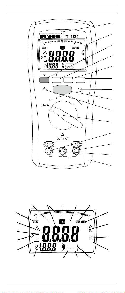
Bild 1: Gerätefrontseite
Fig. 1: Front tester panel
Fig. 1: Panneau avant de l‘appareil
фигура 1: Преден панел на уреда
Obr. 1: Čelní strana přístroje
Εικόνα 1: Εμπρόσθια πρόσοψη συσκευής
AQB
S
100k
0
AUTO
R
SENSE
P
O
Bild 2: Displayanzeige
Fig. 2: Digital display
Fig. 2: Écran numérique
фигура 2: Цифров дисплей
Obr. 2: Digitální zobrazení
Εικόνα 2: Ψηφιακή ένδειξη
02/ 2011
MFLGK
BENNING IT 101
> 660 V
INSULATION
COM
CAT.IV
FUSED
600 V
1. ábra: Készülék előlap
Ill. 1: Lato anteriore apparecchio
Fig. 1: Voorzijde van het apparaat
Rysunek 1: Panel przedni przyrządu
Imaginea 1: Partea frontală a aparatului
Bild 1: Framsida
C
DNE
100M
10M
100kM
LOCK
COMPARE
V
DARPI
2. ábra: Digitális kijelző
Ill. 2: Display digitale
Fig. 2: Digitaal display
Rysunek 2: Wyświetlacz cyfrowy
Imaginea 2: Afişajul digital
Bild 2: Digitalskärm
V
10Gk
100Gk
V
KMΩ
GΩ
µmA
100200
500KMΩ
H
I
J
L
M
N

D F H I S
Bild 3: Spannungsmessung mit AUTO SENSE
Funktion
0
OFF
TRUE RMS
0
OFF
TRUE RMS
100M
100kM
10M
10Gk
100k
100Gk
AUTO
SENSE
LOCK
V
KMΩ
GΩ
µmA
COMPARE
100200
V
DARPI
500KMΩ
RECALLPI/DAR
STORECOMP LOCK
PASS
TEST
M
Ω
L
e
a
k
a
g
e
100 V
C
u
250 V
50 V
r
r
e
Ω
n
500 V
t
1000 V
V
V
> 660 V
Ω
INSULATION
COM
CAT.IV
FUSED
600 V
100M
100kM
10M
10Gk
100k
100Gk
AUTO
SENSE
LOCK
V
KMΩ
GΩ
µmA
COMPARE
100200
V
DARPI
500KMΩ
RECALLPI/DAR
STORECOMP LOCK
PASS
TEST
M
Ω
L
e
a
k
a
g
e
100 V
C
u
250 V
50 V
r
r
e
Ω
n
500 V
t
1000 V
V
V
> 660 V
Ω
INSULATION
COM
CAT.IV
FUSED
600 V
Fig. 3: Voltage measurement with AUTO SENSE
function
Fig. 3: Mesure de tension avec fonction « AUTO
SENSE »
фигура 3: Измерване на напрежение с
функцията AUTO SENSE
Obr. 3: Měření napětí s funkcí AUTO SENSE
Εικόνα 3: Μέτρηση της τάσης με την επιλογή
λειτουργίας AUTO SENSE
3. ábra: Feszültségmérés AUTO SENSE
funkcióban
Ill. 3: Misurazione di tensione con funzione
AUTO SENSE
Fig. 3: Spanningsmeting met AUTO SENSE-
functie
Rysunek 3: Pomiar napięcia z funkcją AUTO SENSE
Imaginea 3: Măsurarea tensiunii cu funcţia AUTO
SENSE
Bild 3: Spänningsmätning med AUTO SENSE-
funktion
Bild 4: Widerstands- und Niederohmmessung
Fig. 4: Resistance and low-resistance
measurement
Fig. 4: Mesure de résistance et de basse
impédance
фигура 4: Измерване на съпротивление и ниско
съпротивление
Obr. 4: Měření odporu a nízkoohmové měření
Εικόνα 4: Μέτρηση ηλεκτρικής αντίστασης και
χαμηλής ωμικής αντίστασης
4. ábra: Ellenállás és kis értékű ellenállás mérés
Ill. 4: Misurazione di resistenza e bassa
resistenza
Fig. 4: Weerstands- en laagohmige meting
Rysunek 4: Pomiar rezystancji i niskiej rezystancji
Imaginea 4: Măsurarea rezistenţei şi a celei de mică
rezistenţă
Bild 4: Mätning av resistans och lågresistans
02/ 2011
0
OFF
TRUE RMS
Bild 5: Isolationswiderstandsmessung
(symbolisch)
100M
100kM
10M
10Gk
100k
100Gk
AUTO
SENSE
LOCK
V
KMΩ
GΩ
µmA
COMPARE
100200
V
DARPI
500KMΩ
RECALLPI/DAR
STORECOMP LOCK
PASS
TEST
M
Ω
L
e
a
k
a
g
e
100 V
C
u
250 V
50 V
r
r
e
Ω
n
500 V
t
1000 V
V
V
> 660 V
Ω
INSULATION
COM
CAT.IV
FUSED
600 V
Fig. 5: Insulating resistance measurement
(symbolic)
Fig. 5: Mesure de résistance d‘isolement
(symbolisée)
фигура 5: Измерване на изолационно
съпротивление (символично)
Obr. 5: Měření izolačního odporu
Εικόνα 5: Μέτρηση ηλεκτρικής μονωτικής
αντίστασης (συμβολικά)
5. ábra: Szigetelési ellenállás mérés (szimbolikus
rajz)
Ill. 5: Misurazione di resistenza d‘isolamento
(simbolico)
Fig. 5: Meten van isolatieweerstand (symbolisch)
Rysunek 5: Pomiar rezystancji izolacji (symboliczny)
Imaginea 5: Măsurarea rezistenţei izolaţiei (simbolic)
Bild 5: Mätning av isoleringsresistans
(symboliskt)
BENNING IT 101
D F H I S
Bild 6: Messung Polarisationsindex (PI)/
dielektrische Absorptionsrate (DAR)
Fig. 6: Measuring the polarization index (PI) /
dielectric absorption rate (DAR)
Fig. 6: Mesure de l‘indice de polarisation («PI»)/
du rapport d‘absorption diélectrique
(«DAR»)
фигура 6: Измерване на поляризационен индекс
(Pl)/ ниво на диелектрична абсорбция
(DAR)
Obr. 6: Měření indexu polarizace (PI)/
dielektrické absorpce (DAR)
Εικόνα 6: Μέτρηση του δείκτη πόλωσης (PI)/ του
ρυθμού της διηλεκτρικής απορρόφησης
(DAR)
6. ábra: Polarizácios index (PI) és dielektromos
abszorpcióa arány (DAR) mérése
Ill. 6: Misurazione dell’indice di polarizzazione
(PI)/ indice di assorbimento dielettrico
(DAR)
Fig. 6: Meting polarisatie-index (PI)/ diëlektrische
absorptieratio (DAR)
Rysunek 6: Pomiar wskaźnika polaryzacji (PI) i
absorbcji dielektrycznej (DAR)
Imaginea 6: Măsurarea indexului de polaritate (PI)/
rata de absorbţie dielectrică (DAR)
Bild 6: Mätning av polariseringsindex (PI) och
dielektrisk absorptionsratio (DAR)
Bild 7: Messergebnisse nach PI-Messung
Fig. 7: Measuring results after PI measurement
Fig. 7: Résultats de mesure suite à la mesure
«PI»
фигура 7: Измервателни резултати след Pl
измерване
Obr. 7: Výsledky po měření PI
Εικόνα 7: Αποτελέσματα μέτρησης PI (δείκτης
πόλωσης)
7. ábra: PI mérés mérési eredmények
Ill. 7: Risultati della misurazione di PI
Fig. 7: Meetresultaten na PI-meting
Rysunek 7: Wyniki pomiarów po pomiarze PI
Imaginea 7: Rezultatele măsurătorilor după
măsurarea PI
Bild 7: Mätresultat efter PI-mätning
02/ 2011
Bild 8: Messergebnisse nach DAR-Messung
Fig. 8: Measuring results after DAR
measurement
Fig. 8: Résultats de mesure suite à la mesure
BENNING IT 101
«DAR»
фигура 8: Измервателни резултати след DAR
измерване
Obr. 8: Výsledky po měření DAR
Εικόνα 8: Αποτελέσματα μέτρησης DAR (ρυθμός
διηλεκτρικής απορρόφησης)
8. ábra: DAR mérés mérési eredmények
Ill. 8: Risultati della misurazione di DAR
Fig. 8: Meetresultaten na DAR-meting
Rysunek 8: Wyniki pomiarów po pomiarze DAR
Imaginea 8: Rezultatul măsurătorilor după măsurarea
DAR
Bild 8: Mätresultat efter DAR-mätning

D F H I S
Voltage
Earth-Bond
resistance
Insulation
resistance
50~1000V
DAR PI
DAR
value
PI value
Leakage
current
R30-sec R1-min
Test voltage R1-min R10-min
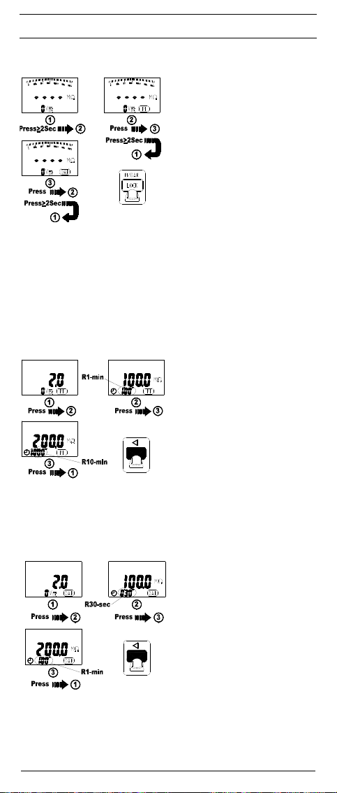
Bild 9: Gespeicherte Messwerte aufrufen
Fig. 9: Calling stored measured values
Fig. 9: Appel des valeurs mesurées mémorisées
фигура 9: Извикване на съхранени измерени
стойности
Obr. 9: Vyvolání uložených naměřených hodnot
Εικόνα 9: Ανάκληση αποθηκευμένων τιμών
μέτρησης
9. ábra: Tárolt mérési érték előhívásal
Ill. 9: Visualizzazione dei valori salvati
Fig. 9: Opgeslagen meetwaarden opvragen
Rysunek 9: Przywołanie zapisanych wartości
Imaginea 9: Apelarea valorilor măsurate şi stocate
(memorate)
Bild 9: Hämta sparade mätvärden
Bild 10: Gespeicherte Werte der
Isolationsmessung
Fig. 10: Stored values of the insulation
measurement
Fig. 10: Valeurs mémorisées de la mesure
d‘isolement
фигура 10: Съхранени стойности от изолационно
измерване
Obr. 10: Uložené hodnoty měření izolace
Εικόνα 10: Αποθηκευμένες τιμές της μέτρησης της
μόνωσης
10. ábra: Tárolt szigetelésmérési értékek
Ill. 10: Valori salvati di misurazione
dell‘isolamento
Fig. 10: Opgeslagen waarden van de
isolatiemeting
Rysunek 10:
Zapisane wartości pomiaru izolacji
Imaginea 10:
Valori memorate ale măsurării izolaţiei
Bild 10: Sparade värden från isoleringsmätningen
Bild 11: Gespeicherte Werte der DAR-Messung
Fig. 11: Stored values of the DAR measurement
Fig. 11: Valeurs mémorisées de la mesure
«DAR»
фигура 11: Съхранени стойности от DAR
измерване
Obr. 11: Uložené hodnoty měření DAR
Εικόνα 11: Αποθηκευμένες τιμές της μέτρησης DAR
(ρυθμός διηλεκτρικής απορρόφησης)
11. ábra: Tárolt DAR-mérési érték előhívása
Ill. 11: Valori salvati di misurazione del DAR
Fig. 11: Opgeslagen waarden van de DAR-meting
Rysunek 11:
Zapisanych wartości pomiarów DAR
Imaginea 11:
Valori stocate ale măsurării-DAR
Bild 11: Sparade värden från DAR-mätningen
02/ 2011
BENNING IT 101

D F H I S
AUTO
SENSE
LOCK
V
100M
100kM
10Gk
100Gk
100k
0
10M
Bild 12: Gespeicherte Werte der PI-Messung
Fig. 12: Stored values of the PI measurement
Fig. 12: Valeurs mémorisées de la mesure «PI»
фигура 12: Съхранени стойности от Pl измерване
Obr. 12: Uložené hodnoty měření PI
Εικόνα 12: Αποθηκευμένες τιμές της μέτρησης PI
(δείκτης πόλωσης)
12. ábra: Tárolt PI-mérési értékek előhívása
Ill. 12: Valori salvati di misurazione del PI
Fig. 12: Opgeslagen waarden van de PI-meting
Rysunek 12:
Zapisanych wartości pomiarów PI
Imaginea 12:
Valori stocate ale măsurării-PI.
Bild 12: Sparade värden från PI-mätningen
KMΩ
GΩ
µmA
COMPARE
100200
V
DARPI
500KMΩ
RECALLPI/DAR
STORECOMP LOCK
PASS
TEST
M
Ω
L
e
a
k
a
g
e
100 V
C
u
250 V
50 V
Ω
V
OFF
TRUE RMS
Ω
> 660 V
INSULATION
r
r
e
500 V
1000 V
V
Bild 13: Batterie- und Sicherungswechsel
Fig. 13: Battery and fuse replacement
Fig. 13: Remplacement des piles et du fusible
фигура 13: Смяна на батериите и предпазителя
Obr. 13: Výměna baterie a pojistky
Εικόνα 13: Αλλαγή μπαταριών και ηλεκτρικής
ασφάλειας
13. ábra: Telep és biztosító csere
Ill. 13: Sostituzione di batterie e fusibile
Fig. 13: Batterij en zekering vervangen
n
t
Rysunek 13:
Wymiana baterii i bezpiecznika
Imaginea 13:
Schimbarea bateriei şi al siguranţelor
Bild 13: Batteri- /säkringsbyte
Bild 14: Aufwicklung der Sicherheitsmessleitung
Fig. 14: Winding up the safety measuring leads
Fig. 14: Enroulement du câble de mesure de
sécurité
фигура 14: Закрепване на сондите
Obr. 14: Navinutí bezpečnostních měřících kabelů
Εικόνα 14: Περιτύλιξη του μετρητικoύ αγωγού
ασφαλείας
14. ábra: A mérővezetékek felcsavarása
Ill. 14: Avvolgimento dei cavetti di sicurezza
Fig. 14: Wikkelen van de veilighh-
eidsmeetsnoeren
Rysunek 14:
Zwijanie bezpiecznych przewodów
pomiarowych
Imaginea 14:
Înfăşurarea firelor de măsurare pe rama
din cauciuc
Bild 14: Fastlindning av säkerhetsmätkablarna
Bild 15: Aufstellung des BENNING IT 101
Fig. 15: Erecting the BENNING IT 101
Fig. 15: Installation du BENNING IT 101
фигура 15: Повдигане на BENNING IT 101
Obr. 15: Postavení přístroje BENNING IT 101
Εικόνα 15: Τοποθέτηση του BENNING IT 101
15. ábra: A BENNING IT 101 felállítása
Ill. 15: Posizionamento del BENNING IT 101
Fig. 15: Opstelling van de BENNING IT 101
Rysunek 15: Zamontowanie przyrządu BENNING IT 101
Imaginea 15:
Poziţionarea pe verticală a aparatului
BENNING IT 101
Bild 15: Uppställning av BENNING IT 101
02/ 2011
BENNING IT 101
D
Bedienungsanleitung
BENNING IT 101
Isolations- und Widerstandsmessgerät zur
- Isolationswiderstandsmessung
- Niederohmmessung
- Widerstandsmessung
- Gleichspannungsmessung
- Wechselspannungsmessung
- Messung/ Berechnung des Polarisationsindex (PI)
- Messung/ Berechnung der dielektrischen Absorptionsrate (DAR)
Inhaltsverzeichnis
1. Benutzerhinweise
2. Sicherheitshinweise
3. Lieferumfang
4. Gerätebeschreibung
5. Allgemeine Angaben
6. Umgebungsbedingungen
7. Elektrische Angaben
8. Messen mit dem BENNING IT 101
9. Instandhaltung
10. Anwendung des Gummi-Schutzrahmens
11. Umweltschutz
1. Benutzerhinweise
Diese Bedienungsanleitung richtet sich an:
- Elektrofachkräfte (EF), befähigte Personen und
- elektrotechnisch unterwiesene Personen (EuP)
Das BENNING IT 101 ist zur Messung in trockener Umgebung vorgesehen. Es
darf nicht in Stromkreisen mit einer höheren Nennspannung als 600 V DC/ AC
eingesetzt werden (näheres hierzu im Abschnitt 6. „Umgebungsbedingungen“).
In der Bedienungsanleitung und auf dem BENNING IT 101 werden folgende
Symbole verwendet:
02/ 2011
Warnung vor elektrischer Gefahr!
Steht vor Hinweisen, die beachtet werden müssen, um Gefahren
für Menschen zu vermeiden.
Achtung Dokumentation beachten!
Das Symbol gibt an, dass die Hinweise in der Bedienungsanleitung
zu beachten sind, um Gefahren zu vermeiden.
Dieses Symbol auf dem BENNING IT 101 bedeutet, dass das
BENNING IT 101 schutzisoliert (Schutzklasse II) ausgeführt ist.
Dieses Warnsymbol weist darauf hin, dass das BENNING IT 101
nicht in Verteilersystemen mit Spannungen höher als 600 V
angewendet werden darf.
Dieses Symbol auf dem BENNING IT 101 bedeutet, dass das
BENNING IT 101 konform zu den EU-Richtlinien ist.
Dieses Symbol erscheint in der Anzeige für eine entladene
Batterie.
Dieses Symbol auf dem BENNING IT 101 weist auf die
eingebauten Sicherungen hin.
(DC) Gleich- oder (AC) Wechselstrom
Erde (Spannung gegen Erde).
Bitte führen Sie das Gerät am Ende seiner Lebensdauer den zur
Verfügung stehenden Rückgabe- und Sammelsystemen zu.
BENNING IT 101
1

D
2. Sicherheitshinweise
Das Gerät ist gemäß
DIN VDE 0411 Teil 1/ EN 61010 Teil 1
DIN VDE 0413 Teil 1, 2 und 4/ EN 61557 Teil 1, 2 und 4
gebaut und geprüft und hat das Werk in einem sicherheitstechnisch einwand-freien Zustand verlassen. Um diesen Zustand zu erhalten und einen
gefahrlosen Betrieb sicherzustellen, muss der Anwender die Hinweise und
Warnvermerke beachten, die in dieser Anleitung enthalten sind. Fehlverhalten
und Nichtbeachtung der Warnungen kann zu schwerwiegenden Verletzungen
oder zum Tode führen.
Das Gerät darf in Stromkreisen bis zur Überspannungskategorie
IV mit max. 600 V Leiter gegen Erde benutzt werden.
Hierzu sind geeignete Messleitungen zu verwenden.
Bei Messungen innerhalb der Messkategorie III oder der
Messkategorie IV darf das hervorstehende leitfähige Teil einer
Kontaktspitze der Messleitung nicht länger als 4 mm sein.
Vor Messungen innerhalb der Messkategorie III und der
Messkategorie IV müssen, die dem Set beigestellten, mit CAT
III und CAT IV gekennzeichneten, Aufsteckkappen auf die
Kontaktspitzen aufgesteckt werden. Diese Maßnahme dient
dem Benutzerschutz.
Beachten Sie, dass Arbeiten an spannungsführenden Teilen und
Anlagen grundsätzlich gefährlich sind. Bereits Spannungen ab
30 V AC und 60 V DC können für den Menschen lebensgefährlich
sein. Ab einer Eingangsspannung von 30 V AC/ DC erscheint im
Display des BENNING IT 101 das Warnsymbol R, welches
vor dem Anliegen einer gefährlichen Spannung warnt. Zusätzlich
leuchtet die rote Hochspannungs-Kontrollanzeige
Vor jeder Inbetriebnahme überprüfen Sie das Gerät und die
Leitungen auf Beschädigungen.
Achtung! Während der Isolationswiderstandsmessung können
am BENNING IT 101 gefährliche Spannungen auftreten.
Ist anzunehmen, dass ein gefahrloser Betrieb nicht mehr möglich ist, ist das
Gerät außer Betrieb zu setzen und gegen unbeabsichtigten Betrieb zu sichern.
Es ist anzunehmen, dass ein gefahrloser Betrieb nicht mehr möglich ist,
- wenn das Gerät oder die Messleitungen sichtbare Beschädigungen aufweisen,
- wenn das Gerät nicht mehr arbeitet,
- nach längerer Lagerung unter ungünstigen Verhältnissen,
- nach schweren Transportbeanspruchungen,
- wenn das Gerät oder die Messleitungen feucht sind.
Um eine Gefährdung auszuschließen
- berühren Sie die Messleitungen nicht an den blanken
Messspitzen,
- dekontaktieren Sie bei Spannungsmessung zuerst die
schaltbare Prüfspitze vom BENNING IT 101
- stecken Sie die Messleitungen in die entsprechend
gekennzeichneten Messbuchsen am BENNING IT 101
siehe Bild 1: Gerätefront
- beim Trennen des Messkreises entfernen Sie immer zuerst
die spannungsführende Messleitung (Phase) und dann die
Null Messleitung von der Messstelle
- verwenden Sie das BENNING IT 101 nicht in der Umgebung
von explosiven Gasen oder Stäuben.
9
auf.
Wartung:
Das Gerät nicht öffnen, sie enthält keine durch den Benutzer
wartbaren Komponenten. Reparatur und Service kann nur
durch qualifiziertes Personal erfolgen.
Reinigung:
Das Gehäuse regelmäßig mit einem Tuch und Reinigungsmittel
trocken abwischen. Kein Poliermittel oder Lösungsmittel
verwenden.
02/ 2011
BENNING IT 101
2

D
3. Lieferumfang
Zum Lieferumfang des BENNING IT 101 gehören:
3.1 ein Stück BENNING IT 101
3.2 zwei Stück Sicherheitsmessleitungen, rot/ schwarz, (L = 1,2 m)
3.3 zwei Stück Sicherheitskrokodilklemmen, rot/ schwarz, 4 mm Stecktechnik
3.4 ein Stück schaltbare Prüfspitze mit integrierter TEST-Taste (T.Nr. 044115)
3.5 ein Stück Gummi-Schutzrahmen
3.6 ein Stück Magnetaufhänger mit Adapter und Riemen (T.Nr. 044120)
3.7 ein Stück Kompakt-Schutztasche
3.8 vier Stück 1,5 V Mignon-Batterien/ Typ AA, IEC LR6 und eine Sicherung
(zur Erstbestückung im Gerät eingebaut)
3.9 eine Bedienungsanleitung
Hinweis auf Verschleißteile:
- Das BENNING IT 101 enthält eine Sicherung zum Überlastschutz:
Ein Stück Sicherung Nennstrom 315 mA (1000 V), 10 kA, FF, D = 6,3 mm,
L = 32 mm (T.Nr. 757213)
- Das BENNING IT 101 wird durch vier eingebaute 1,5 V Mignon-Batterien/
Typ AA, IEC LR6 gespeist.
4. Gerätebeschreibung
siehe Bild 1: Gerätefrontseite
siehe Bild 2: Digitalanzeige
Die in Bild 1 und 2 angegebenen Anzeige- und Bedienelemente werden wie
folgt bezeichnet:
1
Sensor, der automatischen Hintergrundbeleuchtung
2
Digitalanzeige
A
AUTO SENSE, für automatische Erkennung der Gleich- (DC) und Wechsel-
spannung (AC),
B Digitalanzeige, für den Messwert und analoge Bargraphanzeige,
C TEST, erscheint bei Aktivierung der Messung des Isolationswiderstandes
und niederohmigen Widerstands
D LOCK (Feststellung), ermöglicht eine fortlaufende (kontinuierliche)
Messung von Isolationswiderstand und niederohmigen Widerstand,
E APO, erscheint bei automatischer Abschaltung (Auto Power Off),
F LPF, erscheint bei aktiviertem Tiefpassfilter (Low Pass Filter),
G
AC/ DC, erscheint bei gemessener Gleich- (DC) und Wechselspannung (AC),
H , erscheint bei Kompensation (Nullabgleich) der Messleitungen,
I Bereichsanzeigen,
J COMPARE, erscheint bei der Vergleichsfunktion in der Iso la tions wi der-
stands mes sung,
K DAR, erscheint bei aktivierter Messung der dielektrischen Absorptionsrate
L PI, erscheint bei aktivierter Messung des Polarisationsindex
M Prüfspannungsanzeige, erscheint bei der Messung des Isolations wider-
stands,
N Uhr, Messzeit der PI-/ DAR-Messung
O Batterieanzeige „ “, erscheint bei entladener Batterie,
P Bereichsüberschreitung,
Q Polaritätsanzeige,
R (Hochspannungs-Kontrollanzeige), erscheint vor dem Anliegen einer
gefährlichen Spannung,
S MEM, erscheint bei aktiviertem internen Messwertspeicher,
3
Taste (blau), Umschalttaste für die Zweitfunktion
4
COMP-Taste, aktiviert die Vergleichsfunktion in der Isolations wider stands-
messung,
5
STORE/ RECALL-Taste, Speicherung und Aufruf von Messwerten,
6
LOCK (Feststellung)/ PI/ DAR-Taste, für die fortlaufende Messung von
Isolationswiderstand und niederohmigem Widerstand, sowie für die Er mittlung des Polarisationsindex und der dielektrischen Absorptionsrate
7
Grüne LED (PASS), Kontrollanzeige leuchtet auf, wenn der gemes-
sene Wert den Vergleichswert (Widerstandswert) im COMP-Modus überschreitet.
8
TEST-Taste, aktiviert die Messung des Isolationswiderstandes und nie-
derohmigen Widerstandes,
9
Rote LED (Hochspannungs-Kontrollanzeige), leuchtet beim Anliegen
einer gefährlichen Spannung auf,
J
Drehschalter, für die Wahl der Messfunktionen,
K
Ω-Buchse, für Widerstands- und Niederohmmessungen,
L
Buchse (positive), für Spannungs- und Isolationsmessungen,
Polarisationsindex (PI), dielektrische Absorptionsrate (DAR),
M
COM-Buchse, gemeinsame Buchse für Spannungs-, Widerstands-,
Niederohm-, Isolationsmessungen, Polarisationsindex (PI), dielektrische
02/ 2011
BENNING IT 101
3

D
Absorptionsrate (DAR)
N
Gummi-Schutzrahmen.
5. Allgemeine Angaben
Das BENNING IT 101 führt elektrische Messungen zum Isolationswiderstand aus.
Das BENNING IT 101 unterstützt elektrische Sicherheitsprüfungen nach DIN
VDE 0100, IEC 60364, VDE 0701-0702, BGV A3, ÖVE/ ÖNORM E8701 und
NEN 3140.
Voreingestellte Grenzwerte erleichtern die Bewertung.
5.1 Allgemeine Angaben zum Isolationswiderstandsmessgerät
5.1.1 Die Digitalanzeige B für den Messwert B ist als 3½-stellige Flüssig-
kristallanzeige mit 15 mm Schrifthöhe und Dezimalpunkt ausgeführt.
Der größte Anzeigewert ist 4000.
5.1.2 Die Bargraphanzeige B besteht aus 49 Segmenten und zeigt den
Widerstand in einer logarithmischen Skala an.
5.1.3 Die Polaritätsanzeige Q wirkt automatisch. Es wird nur eine Polung
entgegen der Buchsendefinition mit ,,-" angezeigt.
5.1.4 Die Digitalanzeige für die Prüfspannung M ist als 3½-stellige Flüssig -
kristallanzeige mit 7 mm Schrifthöhe ausgeführt. Der größte Anzeigewert ist 1999.
5.1.5 Die Bereichsüberschreitung der Digitalanzeige wird durch ein „>"
Symbol P angezeigt.
5.1.6 Das BENNING IT 101 besitzt eine automatische Messbereichswahl.
5.1.7 Das BENNING IT 101 besitzt eine automatische Hintergrundbeleuchtung
(Auto Backlight). Im Kopfbereich befindet sich der Helligkeitssensor 1.
Sinkt die Umgebungsbeleuchtung, schaltet sich die Hinter grund beleuchtung automatisch ein.
5.1.8 Einmal ertönt ein akustisches Signal (Summer) bei jedem gültigen
Tastendruck und zweimal bei einem ungültigen Tastendruck.
5.1.9 Die Taste (blau) 3 wählt die Zweitfunktion der Drehschalterstellung an.
In der Schalterstellung V wird der Tiefpassfilter (LPF) aktiviert. In der
Stellung Ω wird eine Kompensation (Nullabgleich) der Messleitungen
ermöglicht ( ). In den Schalterstellungen 50 V/ 100 V/ 250 V/ 500 V
und 1000 V wird der Isolationswiderstand oder Leckstrom angezeigt.
5.1.10 Die Taste COMP 4 aktiviert die Vergleichsfunktion in der Iso la tions wi-
der standsmessung.
5.1.11 Die Taste STORE/ RECALL 5 dient dem Speichern und Aufrufen von
Messwerten.
5.1.12 Die Taste LOCK (Feststellung) 6 ermöglicht fortlaufende Messungen
von Iso lationswiderstand und niederohmigem Widerstand, ohne ein
erneutes Betätigen bzw. Festhalten der TEST-Taste 8. Für eine fortlaufende Messung betätigen Sie die LOCK-Taste, betätigen Sie dann
die TEST-Taste. Im Display 2 erscheint das „LOCK“-Symbol D. Bei
der Messung des Isolationswiderstandes bewirkt die TEST-Taste ein
fortlaufendes Anlegen der Prüfspannung an die Messstelle. Bei der
Niederohmmessung bewirkt die TEST-Taste ein fortlaufendes Anlegen
des Prüfstromes an die Messstelle. Die Feststellung kann durch
Betätigen der LOCK-Taste oder TEST-Taste beendet werden.
Im Modus der Feststellung (LOCK-Taste) erkennt das
BENNING IT 101 keine Fremdspannung an dem Eingang des
Gerätes. Stellen Sie sicher, dass die Messstelle spannungsfrei
ist bevor Sie die Feststellung aktivieren, da sonst die Sicherung
durchbrennen könnte.
Die Taste LOCK aktiviert die Messung der dielektrischen Absorptionsrate
(DAR) K und des Polarisationsindex (PI) L.
5.1.13 Die grüne LED 7 (PASS-Kontrollanzeige) leuchtet in der
Vergleichsfunktion (Taste COMP 4), wenn der gemessene Wert den
Vergleichswert (Widerstandswert) überschreitet.
5.1.14 Die Taste TEST 8 aktiviert die Messung des Isolationswiderstandes
und des niederohmigen Widerstandes.
5.1.15 Die rote LED 9 ( Hochspannungs-Kontrollanzeige), leuchtet
beim Anliegen einer gefährlichen Spannung auf. Im Display 2 des
BENNING IT 101 erscheint das Warnsymbol R.
5.1.16 Das BENNING IT 101 wird durch den Drehschalter J ein- oder ausge-
schaltet. Ausstellung „OFF“.
5.1.17 Das BENNING IT 101 schaltet sich nach ca. 20 Min. selbsttätig aus. Im
Modus der Feststellung („LOCK“) D (fortlaufende Messung) erfolgt die
Abschaltung nach ca. 30 Min. Eine Wiedereinschaltung erfolgt automatisch durch Tastenbetätigung, Drehung des Mess be reichs dreh schalters
oder durch Anlegen einer Spannung ab 30 V AC/ DC an den Eingang
des Gerätes.
02/ 2011
BENNING IT 101
4

D
5.1.18 Temperaturkoeffizient des Messwertes: 0,15 x (angegebene Mess ge-
nauig keit)/ °C < 18 °C oder > 28 °C, bezogen auf den Wert bei der
Referenztemperatur von 23 °C.
5.1.19 Das BENNING IT 101 wird durch vier Mignon-Batterien 1,5 V gespeist
(IEC LR6/ AA).
Sobald das Batteriesymbol O erscheint, tauschen Sie umge-
hend die Batterien gegen neue Batterien aus, um eine Gefährdung
durch Fehlmessungen für den Menschen zu vermeiden.
5.1.20 Bei voller Batteriekapazität ermöglicht das BENNING IT 101 eine
Anzahl von ca.
- 2600 Niederohmmessungen (gemäß EN 61557-4) [1 Ω, bei 5 Sek.
- 1100 Messungen des Isolationswiderstandes (1000 V) (gemäß EN
5.1.21 Geräteabmessungen:
(L x B x H) = 200 x 85 x 40 mm ohne Gummi-Schutzrahmen
(L x B x H) = 207 x 95 x 52 mm mit Gummi-Schutzrahmen
Gerätegewicht:
470 g ohne Gummi-Schutzrahmen
630 g mit Gummi-Schutzrahmen
5.1.22 Die mitgelieferten Sicherheitsmessleitungen sind ausdrücklich für die
5.1.23 Das BENNING IT 101 wird durch einen Gummi-Schutzrahmen N vor
6. Umgebungsbedingungen
- Das BENNING IT 101 ist für Messungen in trockener Umgebung vorge-
- Barometrische Höhe bei Messungen: maximal 2000 m
- Überspannungskategorie/ Aufstellungskategorie: IEC 61010-1 → 600 V
- Verschmutzungsgrad: 2
- Schutzart: IP 40 (DIN VDE 0470-1, IEC/ EN 60529)
4 - erste Kennziffer: Schutz gegen kornförmige Fremdkörper
0 - zweite Kennziffer: Kein Wasserschutz,
- EMC: EN 61326-1
- Arbeitstemperatur und relative Luftfeuchte:
Bei Arbeitstemperatur von 0 °C bis 30 °C: relative Luftfeuchte kleiner 80 %,
Bei Arbeitstemperatur von 31 °C bis 40 °C: relative Luftfeuchte kleiner 75 %,
Bei Arbeitstemperatur von 41 °C bis 50 °C: relative Luftfeuchte kleiner 45 %,
- Lagerungstemperatur: Das BENNING IT 101 kann bei Temperaturen von
7. Elektrische Angaben
Bemerkung: Die Messgenauigkeit wird angegeben als Summe aus
- einem relativen Anteil des Messwertes und
- einer Anzahl von Digit (d.h. Zahlenschritte der letzten Stelle).
Diese Messgenauigkeit gilt bei Temperaturen von 18 °C bis 28 °C und einer
relativen Luftfeuchtigkeit kleiner 80 %.
7.1 Spannungsbereiche (Schalterstellung V)
Optische Warnung bei einer gefährlichen Spannung ab 30 V AC/ DC ()
Minimale Messspannung: 0,6 V (AC)
Überspannungsschutz: 600 V RMS oder DC
Grenzfrequenz des Tiefpassfilters (LPF): 1 kHz
Eingangsimpedanz: 3 MΩ/ weniger als 100 pF
02/ 2011
Messdauer] oder
61557-2) [1 MΩ, bei 1000 V und 5 Sek. Messdauer]
Nennspannung und dem Nennstrom des BENNING IT 101 geeignet.
mechanischer Beschädigung geschützt. Der Gummi-Schutzrahmen
ermöglicht es, das BENNING IT 101 während der Messungen aufzustellen oder aufzuhängen.
sehen
Kategorie IV
- 20 °C bis + 60 °C (Luftfeuchte 0 bis 80 %) gelagert werden. Dabei sind
die Batterien aus dem Gerät herauszunehmen.
Messbereich Auflösung Messgenauigkeit
600 V DC 0,1 V ± (1,0 % des Messwertes + 5 Digit)
± (1,5 % des Messwertes + 5 Digit)
600 V AC 0,1 V
600 V AC
mit Tiefpassfilter (LPF)
0,1 V
BENNING IT 101
im Frequenzbereich 50 Hz - 60 Hz
± (2,0 % des Messwertes + 5 Digit)
im Frequenzbereich 61 Hz - 500 Hz
± (1,5 % des Messwertes + 5 Digit)
im Frequenzbereich 50 Hz - 60 Hz
± (5,0 % des Messwertes + 5 Digit)
im Frequenzbereich 61 Hz - 400 Hz
5
D
AC Umrechnung:
AC Umrechnung ist kapazitiv gekoppelt (AC-gekoppelt), TRUE RMS Verhalten,
kalibriert auf ein Sinus-Signal. Bei nichtsinusförmigen Kurvenformen wird der
Anzeigewert ungenauer. So ergibt sich für folgende Crest-Faktoren ein zusätzlicher Fehler:
Crest Faktor von 1,4 bis 2,0 zusätzlicher Fehler + 1,0 %
Crest Faktor von 2,0 bis 2,5 zusätzlicher Fehler + 2,5 %
Crest Faktor von 2,5 bis 3,0 zusätzlicher Fehler + 4,0 %
7.2 Isolationswiderstandsbereiche
(Schalterstellung MΩ, 50 V/ 100 V/ 250 V/ 500 V/ 1000 V)
Messbereich Auflösung Messgenauigkeit
4 MΩ 0,001 MΩ ± (1,5 % des Messwertes + 5 Digit)
40 MΩ 0,01 MΩ ± (1,5 % des Messwertes + 5 Digit)
400 MΩ 0,1 MΩ ± (3,0 % des Messwertes + 5 Digit)
4000 MΩ 1 MΩ ± (3,0 % des Messwertes + 5 Digit)
4,1 GΩ ... 20 GΩ 0,1 GΩ ± (10 % des Messwertes + 3 Digit)
Minimaler/ maximaler Widerstand in Abhängigkeit der Prüfspannung:
Prüfspannung
50 V 50 kΩ 50 MΩ
100 V 100 kΩ 100 MΩ
250 V 250 kΩ 250 MΩ
500 V 500 kΩ 500 MΩ
1000 V 1 MΩ 20 GΩ
Genauigkeit Prüfspannung: - 0 %, + 20 %
Kurzschlussstrom: 1 mA (nominal)
Automatische Entladefunktion: Entladezeit < 1 Sek. für C < 1 µF
Maximale kapazitive Last: funktionsbereit bis zu 1 µF Last
Detektion eines angeschlossenen Stromkreises: wenn > 30 V AC/ DC, dann
7.3 Widerstandsbereiche (Niederohmbereich) (Schalterstellung Ω)
Messbereich Auflösung Messgenauigkeit
40 Ω 0,01 Ω ± (1,5 % des Messwertes + 5 Digit)*
400 Ω 0,1 Ω ± (1,5 % des Messwertes + 3 Digit)
4000 Ω 1 Ω ± (1,5 % des Messwertes + 3 Digit)
40 kΩ 0,01 kΩ ± (1,5 % des Messwertes + 3 Digit)
* < 1 Ω zusätzlich 3 Digit
Prüfspannung: > 4 V und 8 V
Kurzschlussstrom: > 200 mA
Detektion eines angeschlossenen Stromkreises: wenn > 2 V AC/ DC,
8. Messen mit dem BENNING IT 101
8.1 Vorbereiten der Messung
Benutzen und lagern Sie das BENNING IT 101 nur bei den angegebenen
Lager- und Arbeitstemperaturen, vermeiden sie dauernde Sonneneinstrahlung.
- Angaben von Nennspannungen und Nennstrom auf den Sicherheitsmessleitungen überprüfen. Die zum Lieferumfang gehörenden Sicherheitsmessleitungen entsprechen in Nennspannung und Nennstrom dem
BENNING IT 101.
- Isolation der Sicherheitsmessleitungen überprüfen. Wenn die Isolation
beschädigt ist, sind die Sicherheitsmessleitungen sofort auszusondern.
- Sicherheitsmessleitungen auf Durchgang prüfen. Wenn der Leiter in der
Sicherheitsmessleitung unterbrochen ist, sind die Sicherheitsmessleitungen
sofort auszusondern.
- Bevor am Drehschalter J eine andere Funktion gewählt wird, müssen die
Sicherheitsmessleitungen von der Messstelle getrennt werden.
- Starke Störquellen in der Nähe des BENNING IT 101 können zu instabiler
Anzeige und zu Messfehlern führen.
02/ 2011
Minimaler Widerstand
(bei 1 mA)
BENNING IT 101
Maximaler Widerstand
dann
6

D
8.2 Spannungsmessung mit AUTO SENSE Funktion (automatische AC/
DC-Erkennung)
- Dekontaktieren Sie die schaltbare Prüfspitze vom BENNING IT 101.
- Mit dem Drehschalter J die gewünschte Funktion (V) wählen.
- Die schwarze Sicherheitsmessleitung mit der COM-Buchse M am
BENNING IT 101 kontaktieren.
- Die rote Sicherheitsmessleitung mit der Buchse für V, Insulation L am
BENNING IT 101 kontaktieren.
- Die Sicherheitsmessleitungen mit der Messstelle kontaktieren und den
Messwert im Display 2 am BENNING IT 101 ablesen.
- Spannungen größer 660 V AC/ DC werden im Display mit „
angezeigt.
- Ein blinkendes Warnsymbol R erscheint im Display bei Spannungen ab
30 V AC/ DC.
Das BENNING IT 101 zeigt entweder eine DC (Gleich) oder AC
(Wechselspannung) an. Falls die gemessene Spannung einen
DC- und einen AC-Anteil aufweist, wird immer nur die größere
Komponente angezeigt. Bei AC (Wechselspannung) wird der
Messwert durch eine Mittelwertgleichrichtung gewonnen und
als Effektivwert angezeigt.
siehe Bild 3: Spannungsmessung mit AUTO SENSE Funktion
8.2.1 Spannungsmessung mit Tiefpassfilter (LPF)
- Das BENNING IT 101 besitzt einen integrierten Tiefpassfilter, mit einer
Grenzfrequenz von 1 kHz.
- Mit der Taste (blau) 3 am BENNING IT 101 wird der Tiefpassfilter aktiviert
(Taste einmal drücken).
- Ist der Filter aktiv, wird im Display 2 gleichzeitig das Symbol „LPF“ F
eingeblendet.
8.3 Widerstands- und Niederohmmessung
- Schalten Sie den Schaltkreis bzw. den Prüfling spannungsfrei.
- Mit dem Drehschalter J die gewünschte Funktion (Ω) wählen.
- Die schwarze Sicherheitsmessleitung mit der COM-Buchse M am
BENNING IT 101 kontaktieren.
- Die rote Sicherheitsmessleitung mit der Ω-Buchse K am BENNING IT 101
kontaktieren.
- Um eine Kompensation (Nullabgleich) des Messleitungswiderstandes
durchzuführen, kontaktieren Sie die Messleitungen (kurzschließen) und
drücken Sie die blaue Taste 3. Der Nullabgleich ist erfolgt, sobald im
Display 2 „ “ H erscheint.
- Die Sicherheitsmessleitungen mit der Messstelle kontaktieren, Taste
TEST 8 betätigen und den Messwert im Display 2 am BENNING IT 101
ablesen.
- Bei einer Spannung ab 2 V AC/ DC warnt zusätzlich ein blinkendes
Warnsymbol R vor dem Anliegen einer Fremdspannung und die
Widerstandsmessung wird abgebrochen. Schalten Sie den Schaltkreis
spannungsfrei und wiederholen Sie die Messung.
- Der Widerstandswert wird über das Display 2 angezeigt. Widerstände
größer 40 kΩ werden im Display mit „>40kΩ“ angezeigt.
- Um den Widerstandswert kontinuierlich zu messen, drücken Sie die
Taste LOCK 6 und dann die Taste TEST 8. Der Wert wird kontinuierlich
gemessen bis die Taste TEST 8 oder LOCK 6 erneut gedrückt wird.
siehe Bild 4: Widerstands- und Niederohmmessung
8.4 Isolationswiderstandsmessung
Maximale Spannung gegen Erdpotential beachten!
Elektrische Gefahr!
Die höchste Spannung, die an den Buchsen,
- COM-Buchse
- Buchse für V, Insulation
des BENNING IT 101 gegenüber Erde liegen darf, beträgt 600 V. Vermeiden Sie
bei den Messungen Lichtbögen längerer Zeitdauer zwischen den Prüfspitzen/
Messstellen, diese können zu Gerätestörungen führen.
M
L
>660 V AC/DC
“
02/ 2011
BENNING IT 101
7

D
Während der Isolationswiderstandsmessung können an den
Prüfspitzen des BENNING IT 101 gefährliche Spannungen
auf treten. Beachten Sie, dass diese gefährlichen Spannungen
eben falls an blanken Metallteilen des Schaltkreises auftreten
können. Berühren Sie nicht die Prüfspitzen bei Stellung des
Drehschalters J auf Pos. 50 V, 100 V, 250 V, 500 V oder 1000 V.
- Schalten Sie den Schaltkreis bzw. den Prüfling spannungsfrei.
- Mit dem Drehschalter J die gewünschte Funktion (MΩ) wählen.
- Die schwarze Sicherheitsmessleitung mit der COM-Buchse M am
BENNING IT 101 kontaktieren.
- Die rote Sicherheitsmessleitung mit der Buchse für V, Insulation L am
BENNING IT 101 kontaktieren.
- Die Sicherheitsmessleitungen mit der Messstelle kontaktieren.
- Bei einer Spannung ab 30 V AC/ DC warnt ein blinkendes Warn symbol
R vor dem Anliegen einer Fremdspannung und die Iso lations wider -
standsmessung wird abgebrochen. Schalten Sie den Schaltkreis spannungs frei und wiederholen Sie die Messung.
- Zum Start der Messung betätigen Sie die Taste TEST 8.
- Drücken Sie die blaue Taste 3, um den Isolationswiderstand oder den
Leckstrom anzuzeigen.
- Um den Isolationswiderstand kontinuierlich zu messen, drücken Sie zuerst
die Taste LOCK 6 und dann die Taste TEST 8. Der Wert wird kontinuierlich gemessen bis die Taste TEST 8 oder LOCK 6 erneut gedrückt wird.
Vor dem Entfernen der Messleitungen die Taste TEST
loslassen und warten bis die anliegende Spannung auf
0 V zurückgegangen ist. Beachten Sie, dass so interne
Energiespeicher des Prüflings über das Messgerät entladen
werden.
- Widerstandswerte größer als der Messbereich werden im Display 2 mit „>“
P angezeigt.
siehe Bild 5: Isolationswiderstandsmessung (symbolisch)
8.4.1 Compare-Funktion (Vergleichsfunktion)
- Das Isolationswiderstandsmessgerät BENNING IT 101 besitzt 12 ge speicherte Grenzwerte:
100 kΩ, 200 kΩ, 500 kΩ, 1 MΩ, 2 MΩ, 5 MΩ, 10 MΩ, 20 MΩ, 50 MΩ,
100 MΩ, 200 MΩ und 500 MΩ.
- Vor Beginn der Messung drücken Sie die Taste COMP 4, um den
Grenzwert auszuwählen. Im Vergleichsmodus erscheint die Symbolik
„COMPARE“ J und der ausgewählte Grenzwert wird unten rechts
im Display 2 angezeigt. Die Vergleichfunktion ermöglicht eine direkte
Überprüfung auf Unterschreitung der Grenzwerte.
- Die grüne LED der PASS Kontrollanzeige 7 leuchtet, wenn der gemessene
Wert den Vergleichwert (Widerstandswert) überschreitet.
- Durch Drücken der Taste COMP 4 kann der Grenzwerte ausgewählt und
aktiviert werden.
- Durch längeren Tastendruck (2 Sekunden) der Taste COMP 4 wird die
Vergleichsfunktion deaktiviert.
8.5 Polarisationsindex (PI) und dielektrische Absorptionsrate (DAR)
- Schalten Sie den Schaltkreis bzw. den Prüfling spannungsfrei.
- Mit dem Drehschalter J die gewünschte Prüfspannung im Messbereich
(MΩ) wählen.
- Um den Polarisationsindex (PI) zu ermitteln, drücken Sie länger (2
Sekunden) die Taste LOCK 6 (PI/DAR). Im Display 2 erscheint das
Symbol „PI“ L. Durch erneuten Tastendruck kann gewählt werden zwischen der Messung der dielektrischen Absorptionsrate (DAR) und des
Polarisationsindex (PI). Die ausgewählte Messung (PI L oder DAR K) wird
im Display 2 angezeigt.
- Die schwarze Sicherheitsmessleitung mit der COM-Buchse M am
BENNING IT 101 kontaktieren.
- Die rote Sicherheitsmessleitung mit der Buchse für V, Insulation L am
BENNING IT 101 kontaktieren.
- Die Sicherheitsmessleitungen mit der Messstelle kontaktieren.
- Bei einer Spannung ab 30 V AC/ DC warnt zusätzlich ein blinkendes
Warnsymbol R vor dem Anliegen einer Fremdspannung und die
Messung wird abgebrochen. Schalten Sie den Schaltkreis spannungsfrei
und wiederholen Sie die Messung.
- Die Taste TEST 8 startet und unterbricht die Messung.
- Die blaue Taste 3 ermittelt die benötigte Restzeit für die Wertermittlung.
02/ 2011
BENNING IT 101
8
8

D
- Sollte der Messwert den Messbereich überschreiten, erscheint im Display
die Fehlermeldung „Err“.
siehe Bild 6: Messung Polarisationsindex (PI)/ dielektrische
Polarisation Index (PI) = R10-Min/ R1-Min
Mit: R10-Min = gemessener Isolationswiderstand nach 10 Minuten
R1-Min = gemessener Isolationswiderstand nach 1 Minute
Dielektrische Absorptionsrate (DAR) = R1-Min/ R30-Sek
Mit: R1-Min = gemessener Isolationswiderstand nach 1 Minute
R30-Sek = gemessener Isolationswiderstand nach 30 Sekunden
Hinweis:
Ein Polarisation Index > 2 oder eine dielektrische Absorptionsrate > 1,3 sind
kennzeichnend für eine gute Isolationsqualität.
8.5.1 Messergebnisse nach PI- Messung
- Nach Abschluss der Messung wird durch Drücken der Taste „<“ (Taste blau
3
) durch die Messergebnisse gerollt.
siehe Bild 7: Messergebnisse nach PI-Messung
8.5.2 Messergebnisse nach DAR- Messung
- Nach Abschluss der Messung wird durch Drücken der Taste „<“ (Taste blau
3
) durch die Messergebnisse gerollt.
siehe Bild 8: Messergebnisse nach DAR-Messung
8.6 Speicherfunktion
Das BENNING IT 101 besitzt einen internen Messwertspeicher mit 100
Speicher plätzen pro Messfunktion.
8.6.1 STORE (Messwerte speichern)
- Betätigen Sie die Taste STORE/ RECALL 5, um die Messwerte in den
Speicher zu hinterlegen. Mit Tastendruck blinkt das Symbol „MEM“ S auf
und die Anzahl der gespeicherten Messwerte M werden im Display 2
angezeigt. Der Speicher ist in fünf Segmente unterteilt. Jedes Segment
besitzt 100 Speicherplätze.
Spannung Widerstand Isolationswiderstand DAR PI
1 Spannung Widerstand Widerstand DAR-Wert PI-Wert
2 Leckstrom R30-Sek R1-Min
3 Prüfspannung R1-Min R10-Min
Tabelle 1: Speicherwerte der jeweiligen Messung
8.6.2 RECALL (Messwerte aufrufen)
- Um einen gespeicherten Messwert aufzurufen, drücken Sie länger (2
Sekunden) die Taste STORE/ RECALL 5. Das Symbol „MEM“ S und die
Anzahl der gespeicherten Messwerte M erscheinen im Display 2.
- Mit der blauen Taste 3 und der Taste COMP 4 kann durch den Speicher
gerollt werden.
- Wenn der Speicher leer ist, zeigt das Display "nOnE" an.
siehe Bild 9: Gespeicherte Messwerte aufrufen
siehe Bild 10: Gespeicherte Werte der Isolationsmessung
8.6.3 Aufruf der gespeicherten Messwerte der PI/ DAR-Messung
- Drücken Sie länger (2 Sekunden) die Taste LOCK 6 (PI/ DAR). Im Display
2
erscheint das Symbol „PI“ L.
- Wählen Sie die gewünschte Funktion (DAR) K oder (PI) L durch erneuten
Tastendruck aus. Die ausgewählte Funktion wird im Display 2 angezeigt.
- Drücken Sie länger die Taste STORE/ RECALL 5, um in den RECALLModus zu gelangen.
- Mit der blauen Taste 3 und der Taste COMP 4 kann durch den Speicher
gerollt werden.
- Wenn der Speicher leer ist, zeigt das Display "nOnE" an.
siehe Bild 11: Gespeicherte Werte der DAR-Messung
siehe Bild 12: Gespeicherte Werte der PI-Messung
8.6.4 Messwertspeicher löschen
- Um den Messwertspeicher einer Messfunktion (Segment) zu löschen, drücken Sie die Taste STORE/ RECALL 5 länger als 5 Sekunden. Im Display
2
blinkt das Symbol „MEM“ S und „clr“ B zweimal.
02/ 2011
Absorptions rate (DAR)
BENNING IT 101
9

D
- Zum Löschen des kompletten Messwertspeichers (alle Segmente) schalten
Sie das Messgerät aus, drücken und halten Sie die Taste STORE/ RECALL
5
und schalten Sie das Messgerät wieder ein. Im Display 2 erscheint das
Symbol „All“ B „del“ M.
9. Instandhaltung
Vor dem Öffnen das BENNING IT 101 unbedingt spannungsfrei
schalten! Elektrische Gefahr!
Die Arbeit am geöffneten BENNING IT 101 unter Spannung ist ausschließlich
Elektrofachkräften vorbehalten, die dabei besondere Maßnahmen zur
Unfallverhütung treffen müssen.
So machen Sie das BENNING IT 101 spannungsfrei, bevor Sie das Gerät öffnen:
- Entfernen Sie zuerst beide Sicherheitsmessleitungen von der Messstelle.
- Entfernen Sie dann beide Sicherheitsmessleitungen vom
BENNING IT 101.
- Schalten Sie den Drehschalter J in die Schalterstellung „OFF“.
9.1 Sicherstellen des Gerätes
Unter bestimmten Voraussetzungen kann die Sicherheit im Umgang mit dem
BENNING IT 101 nicht mehr gewährleistet sein; zum Beispiel bei:
- Sichtbaren Schäden am Gehäuse,
- Fehlern bei Messungen,
- Erkennbaren Folgen von längerer Lagerung unter unzulässigen
Bedingungen und
- Erkennbaren Folgen von außerordentlicher Transportbeanspruchung.
In diesen Fällen ist das BENNING IT 101 sofort abzuschalten, von den
Messstellen zu entfernen und gegen erneute Nutzung zu sichern.
9.2 Reinigung
Reinigen Sie das Gehäuse äußerlich mit einem sauberen und trockenen Tuch
(Ausnahme spezielle Reinigungstücher). Verwenden Sie keine Lösungs- und/
oder Scheuermittel, um das Gerät zu reinigen. Achten Sie unbedingt darauf,
dass das Batteriefach und die Batteriekontakte nicht durch auslaufendes
Batterie-Elektrolyt verunreinigt werden.
Falls Elektrolytverunreinigungen oder weiße Ablagerungen im Bereich der
Batterie oder des Batteriegehäuses vorhanden sind, reinigen Sie auch diese
mit einem trockenen Tuch.
9.3 Batteriewechsel
Vor dem Öffnen das BENNING IT 101 unbedingt spannungsfrei
schalten! Elektrische Gefahr!
Das BENNING IT 101 wird durch vier 1,5 V Mignonbatterien/Typ AA (IEC
LR 6) gespeist. Ein Batteriewechsel ist erforderlich, wenn im Display 2 das
Batteriesymbol O erscheint.
So wechseln Sie die Batterien:
- Entfernen Sie zuerst beide Sicherheitsmessleitungen von der Messstelle.
- Entfernen Sie dann beide Sicherheitsmessleitungen vom
BENNING IT 101.
- Schalten Sie den Drehschalter J in die Schalterstellung „OFF“.
- Entfernen Sie den Gummi-Schutzrahmen N vom BENNING IT 101.
- Legen Sie das BENNING IT 101 auf die Frontseite und lösen Sie die
Schraube vom Batteriedeckel.
- Heben Sie den Batteriedeckel vom Unterteil ab.
- Entnehmen Sie die entladenen Batterien aus dem Batteriefach.
- Legen Sie die neuen Batterien polrichtig ins Batteriefach.
- Rasten Sie den Batteriedeckel an das Unterteil an und ziehen Sie die
Schraube an.
- Setzen Sie das BENNING IT 101 in den Gummi-Schutzrahmen N ein.
siehe Bild 13: Batterie- und Sicherungswechsel
Leisten Sie Ihren Beitrag zum Umweltschutz! Batterien dürfen
nicht in den Hausmüll. Sie können bei einer Sammelstelle für
Altbatterien bzw. Sondermüll abgegeben werden. Informieren
Sie sich bitte bei ihrer Kommune.
9.4 Prüfen und Auswechseln der Sicherung
Die Funktionsfähigkeit der Sicherung kann wie folgt überprüft werden:
- Entfernen Sie zuerst beide Sicherheitsmessleitungen von der Messstelle.
-
Entfernen Sie dann beide Sicherheitsmessleitungen vom BENNING IT 101.
02/ 2011
BENNING IT 101
10
D
- Mit dem Drehschalter J die Funktion „Ω “ wählen und drücken Sie die
Taste TEST 8.
- Erscheint im Display 2 „FUSE“, ist die Sicherung defekt und muss ausgetauscht werden.
Vor dem Öffnen das BENNING IT 101 unbedingt spannungsfrei
schalten! Elektrische Gefahr!
Das BENNING IT 101 wird durch eine eingebaute Sicherung (315 mA, 1000 V,
10 kA, FF, D = 6,3 mm, L = 32 mm) vor Überlastung geschützt.
So wechseln Sie die Sicherung:
- Entfernen Sie zuerst beide Sicherheitsmessleitungen von der Messstelle.
-
Entfernen Sie dann beide Sicherheitsmessleitungen vom BENNING IT 101.
- Schalten Sie den Drehschalter J in die Schalterstellung „OFF“.
- Entfernen Sie den Gummi-Schutzrahmen N vom BENNING IT 101.
- Legen Sie das BENNING IT 101 auf die Frontseite und lösen Sie die
Schraube vom Batteriedeckel.
- Heben Sie den Batteriedeckel vom Unterteil ab.
- Heben Sie ein Ende der defekten Sicherung seitlich mit einem
Schlitzschraubendreher aus dem Sicherungshalter.
- Entnehmen Sie die defekte Sicherung vollständig aus dem
Sicherungshalter.
- Setzen Sie die neue Sicherung ein. Verwenden Sie nur Sicherungen mit
gleichem Nennstrom, gleicher Nennspannung, gleichem Trennvermögen,
gleicher Auslösecharakteristik und gleichen Abmessungen.
- Ordnen Sie die neue Sicherung mittig in dem Halter an.
- Rasten Sie den Batteriedeckel an das Unterteil an und ziehen Sie die
Schraube an.
- Setzen Sie das BENNING IT 101 in den Gummi-Schutzrahmen N ein.
siehe Bild 13: Batterie- und Sicherungswechsel
9.5 Kalibrierung
Um die angegebenen Genauigkeiten der Messergebnisse zu erhalten, muss
das Gerät regelmäßig durch unseren Werksservice kalibriert werden. Wir
empfehlen ein Kalibrierintervall von einem Jahr. Senden Sie hierzu das Gerät
an folgende Adresse:
Benning Elektrotechnik & Elektronik GmbH & Co. KG
Service Center
Robert-Bosch-Str. 20
D – 46397 Bocholt
9.6 Ersatzteile
Sicherung FF 315 mA, 1000 V, 10 kA, D = 6,3 mm, L = 32 mm T.Nr. 757213
10. Anwendung des Gummi-Schutzrahmens
- Sie können die Sicherheitsmessleitungen verwahren, indem Sie die
Sicherheitsmessleitungen um den Gummi-Schutzrahmen N wickeln und
die Spitzen der Sicherheitsmessleitungen geschützt an den GummiSchutzrahmen anrasten.
- Sie können eine Sicherheitsmessleitung so an den Gummi-Schutzrahmen
anrasten, dass die Messspitze freisteht, um die Messspitze gemeinsam mit
dem BENNING IT 101 an einen Messpunkt zu führen.
- Die rückwärtige Stütze am Gummi-Schutzrahmen ermöglicht, das
BENNING IT 101 schräg aufzustellen (erleichtert die Ablesung) oder aufzuhängen.
- Der Gummi-Schutzrahmen besitzt eine Öse, die für eine Aufhängemöglichkeit
genutzt werden kann.
siehe Bild 14: Aufwicklung der Sicherheitsmessleitung
siehe Bild 15: Aufstellung des BENNING IT 101
11. Umweltschutz
Bitte führen Sie das Gerät am Ende seiner Lebensdauer den zur
Verfügung ste hen den Rückgabe- und Sammelsystemen zu.
02/ 2011
BENNING IT 101
11
Operating instructions
BENNING IT 101
Insulation and resistance measuring instrument for:
- Insulating resistance measurements
- Low-resistance measurements
- Resistance measurements
- Direct voltage measurements
- Alternating voltage measurements
- Measuring/ calculating the polarization index (PI)
- Measuring/ calculating the dielectric absorption rate (DAR)
Contents
1. User notes
2. Safety note
3. Scope of delivery
4. Description of appliance tester
5. General information
6. Ambient conditions
7. Electrical specifications
8. Measuring with the BENNING IT 101
9. Maintenance
10. Application of rubber protection frame
11. Environmental note
1. User notes
These operating instructions are intended for
- qualified electricians, competent persons and
- electrotechnically trained persons
The BENNING IT 101 is intended for making measurements in dry environment.
It must not be used in power circuits with a nominal voltage higher than 600 V
DC/ AC (more details in Section 6. “Ambient conditions”).
The following symbols are used in these operating instructions and on the
BENNING IT 101:
Warning of electrical danger!
Indicates instructions which must be followed to avoid danger
to persons.
Important, comply with the documentation!
This symbol indicates that the stipulations in the operating
instructions must be followed in order to avoid danger.
This symbol on the BENNING IT 101 means that the
BENNING IT 101 is totally insulated (protection class II).
This warning symbol indicates that the BENNING IT 101 must
not be used in distribution systems with voltages higher than
600 V.
This symbol on the BENNING IT 101 means that the
BENNING IT 101 complies with the EU directives.
This symbol appears on the display to indicate a discharged
battery.
This symbol on the BENNING IT 101 indicates the built-in fuses
(DC) direct current or (AC) alternating current
Earth (voltage to ground)
02/ 2011
At the end of product life, dispose of the unserviceable device via
appropriate collecting facilities provided in your community.
BENNING IT 101
12

2. Safety note
The instrument is built and tested in accordance with
DIN VDE 0411 part 1/ EN 61010 part 1
DIN VDE 0413 part 1, 2 and 4/ EN 61557 part 1, 2 and 4
and has left the factory in perfectly safe technical condition.
To maintain this condition and to ensure safe operation of the appliance tester,
the user must observe the notes and warnings given in these instructions at all
times. Improper handling and non-observance of the warnings might involve
severe injuries or danger to life.
The instrument may be used only in electrical circuits of over
voltage category IV with a maximum voltage of 600 V between
the conductor and ground.
Only use suitable measuring leads for this. With measurements
within measurement category III or measurement category IV,
the projecting conductive part of a contact tip of the measuring
leads must not be longer than 4 mm.
Prior to carrying out measurements within measurement
category III and measurement category IV, the push-on caps
provided with the set and marked with CAT III and CAT IV must
be pushed onto the contact tips. The purpose of this measure
is user protection.
Remember that work on electrical components of all kinds is
dangerous. Even low-voltages of 30 V AC and 60 V DC may
be dangerous to human life. As from an input voltage of 30 V
AC/ DC the warning symbol R appears on the display of
the BENNING IT 101, as a warning that a dangerous voltage
is connected. In addition, the red high-voltage indicator
9
lights up.
Before starting the appliance tester, always check it as well as
all measuring leads and wires for signs of damage.
Important! During the insulating resistance measurement,
dangerous levels of voltage may occur in the BENNING IT 101.
Should it appear that safe operation of the appliance tester is no longer possible,
it should be shut down immediately and secured to prevent that it is switched
on accidentally.
It must be assumed that safe operation is no longer possible
- if the instrument or the measuring leads show visible signs of damage, or
- if the appliance tester no longer works, or
- after long periods of storage under unfavourable conditions, or
- after being subject to rough transportation, or
- if the device is exposed to moisture.
In order to avoid danger,
- do not touch the bare probe tips of the measuring leads
- when measuring voltage disconnect the switchable probe
tip from the BENNING IT 101 at first
- plug the measuring leads into the correspondingly
designated measuring sockets on the BENNING IT 101
see Fig. 1: Front tester panel
- when disconnecting the measuring circuit, always
disconnect the voltage carrying measuring cable (phase)
first and then disconnect the neutral measuring lead
- do not operate the BENNING IT 101 in the vicinity of
explosive gases or dust.
Maintenance:
Do not open the tester, because it contains no components
which can be repaired by the user. Repair and service must be
carried out by qualified personnel only!
Cleaning:
Regularly wipe the housing by means of a dry cloth and
cleaning agent. Do not use any polishing agents or solvents!
02/ 2011
BENNING IT 101
13

3. Scope of delivery
The scope of delivery for the BENNING IT 101 comprises:
3.1 one BENNING IT 101
3.2 two safety measuring leads, red/ black (L = 1.2 m)
3.3 two safety alligator clip, red/ black, 4 mm plug-in system
3.4 one switchable probe tip with integrated TEST key (part no. 044115)
3.5 one rubber protection frame
3.6 one magnetic holder with adapter and strap (part no. 044120)
3.7 one compact protective pouch
3.8 four mignon batteries 1.5 V/ type AA according to IEC LR6 and one fuse
(fitted in unit as initial equipment),
3.9 one operating manual
Parts subject to wear:
- The BENNING IT 101 contains a fuse as protection against overload:
One fuse, nominal current rating 315 mA (1000 V), 10 kA, FF, D = 6.3 mm,
L = 32 mm (part no. 757213)
- The BENNING IT 101 is powered by four mignon batteries 1.5 V/ type AA
according to IEC LR6.
4. Description of the appliance tester
See figure 1: Front side of the instrument
See figure 2: Digital display
The display and operator control elements specified in Fig. 1 and 2 are designated as follows:
1
Sensor, of the automatic background lighting
2
Digital display
A AUTO SENSE, for automatic detection of DC and AC voltage,
B Digital display, for the measured value and analogue bar graph display,
C TEST, appears when the measuring function for insulating resistance and
low resistance is activated,
D LOCK (latching), permits continuous measurement of insulating resistance
and low resistance,
E APO, Auto Power Off is activated,
F LPF, is indicated with the low-pass filter being activated,
G AC/ DC, is indicated when a DC or AC voltage is measured,
H , is indicated in case of compensation (null balance) of the measuring
leads,
I< Range indication,
J COMPARE, is indicated in case of the comparative function of insulating
resistance measurement,
K DAR, is indicated if the measurement of the dielectric absorption rate is
activated,
L PI, is indicated if the measurement of the polarization index is activated,
M Testing voltage indication, is indicated when the insulating resistance is
measured,
N Clock, measuring time of the PI / DAR measurement,
O Battery condition indicator „ “, appears when the battery is dis-
charged,
P Overflow,
Q Polarity indication,
R (high-voltage indicator), is indicated if a dangerous voltage is applied,
S MEM, is indicated when an internal memory of measured values is acti-
vated,
3
Key (blue), change-over key for the secondary function,
4
COMP key, activates the comparative function for insulating resistance
measurement,
5
STORE / RECALL key, storage and call of measured values,
6
LOCK (latching)/ PI/DAR key, permits continuous measurement of insulating resistance and low-resistance as well as activates the measurement of
the dielectric absorption rate and of the polarization index,
7
Green LED (PASS), lights up, if the measured value exceeds the compara-
tive value (resistance value) in the COMP mode,
8
TEST key, activates the measurement of the insulating resistance and of
the low-impedance resistance,
9
Red LED (high-voltage control indicator), lights up if a dangerous voltage
is applied,
J Rotary switch, for selecting the measuring function,
K Ω socket, for resistance and low-resistance measurement,
L Jack (positive), for measuring voltages and insulation, polarization index
(PI), dielectric absorption rate (DAR),
M COM jack, common jack for measurements of voltage, resistance, low-
02/ 2011
BENNING IT 101
14

impedance, insulation, polarization index (PI) and dielectric absorption rate
(DAR)
N Rubber protective frame.
5. General information
The BENNING IT 101 is intended for measuring the insulating resistance.
The BENNING IT 101 supports electric safety tests according to DIN VDE 0100,
IEC 60364, VDE 0701-0702, BGV A3, ÖVE/ ÖNORM E8701 and NEN 3140.
Preset limiting values make it easier to evaluate the test.
5.1 General information concerning the insulation measuring instrument
5.1.1 The digital display B for the measurement readings B is a 3½-digit
liquid crystal display with decimal point. The height of the displayed
digits is 15 mm. The largest numerical value which can be displayed is
4000.
5.1.2 The bar graph display B consists of 49 segments and depicts resist-
ance readings on a logarithmic scale.
5.1.3 The polarity indication Q is automatic. Only one polarity with respect to
the socket marked ” - ” is indicated.
5.1.4 The digital display for the test voltage M is a 3½ digit liquid crystal
display with 7 mm high numerals. The largest value which can be
displayed is 1999.
5.1.5
Range overflow of the digital display 2 is indicated with the symbol ”>” P.
5.1.6 The BENNING IT 101 has an automatic measuring range selection
function (auto ranging).
5.1.7 The BENNING IT 101 is provided with an automatic background light-
ing ("Auto Backlight"). The brightness sensor is located on the top
side of the device 1. As soon as the ambient lighting decreases, the
background lighting will switch on automatically.
5.1.8 An acoustic signal (buzzer) will sound once for each valid keystroke
and twice in case of an invalid keystroke.
5.1.9 The secondary function of the rotary switch position can be selected
by means of the key (blue) 3. The low-pass filter (LPF) is activated
in switch position V. A compensation (null balance) of the measuring
leads is possible with switch position Ω ( ). The insulating resistance
or leakage current is indicated with switch positions 50 V/ 100 V/ 250 V/
500 V and 1000 V.
5.1.10 The COMP key 4 activates the comparative function for insulating
resistance measurement.
5.1.11 The STORE/ RECALL key 5 is intended for storage and call of meas-
ured values.
5.1.12 The key LOCK (latching) 6 permits continuous measurements of insu-
lating resistance and low-resistance without having to press the TEST
key 8 repeatedly or to hold it. To switch over to continuous measurements, press the LOCK key and then the TEST key. The “LOCK”
symbol D appears on the display 2. When measuring the insulating
resistance, pressing the TEST key continually applies the test voltage
to the measuring point. When measuring low-resistance, pressing the
key TEST continually applies the test current to the measuring point.
The locked state can be terminated by pressing the LOCK key or the
TEST key.
In locked mode (key) the BENNING IT 101 recognizes no
external voltage at the input of the instrument. Make sure that
the measuring point is free of voltage before activating the
locked mode, otherwise the fuse might blow.
The LOCK key activates the measurement of the dielectric absorption
rate (DAR) K and of the polarization index (PI) L.
5.1.13 The green LED 7 (PASS indicator) lights for the comparative function
(COMP key 4), if the measured value exceeds the comparative value
(resistance value).
5.1.14. The TEST key 8 activates the measuring function for insulating resist-
ance and low-resistance.
5.1.15 The red LED 9 ( high-voltage control indicator) lights up, if a danger-
ous voltage is applied. The warning symbol R is indicated on the
display 2 of the BENNING IT 101.
5.1.16 The BENNING IT 101 is switched on and off with the rotary switch J.
The off setting is ”OFF”.
5.1.17 The BENNING IT 101 switches itself off automatically after approx.
20 minutes. In locked mode (“LOCK”) D (continuous measurements)
automatic switch off takes place after 30 minutes. The instrument
switches itself on again automatically when a key is actuated, or the
measuring range selector switch is turned, or a voltage higher than
02/ 2011
BENNING IT 101
15
30 V AC/ DC is connected to the input of the instrument.
5.1.18 Temperature coefficient of the measured value: 0.15 x (stated measur-
ing precision)/ °C < 18 °C or > 28 °C, related to the value for the reference temperature of 23° C.
5.1.19 The BENNING IT 101 is powered by four 1.5 V mignon batteries (IEC
LR6/ type AA).
As soon as the battery symbol O is indicated, the batteries
must be replaced by new ones immediately in order to prevent
danger for persons due to incorrect measurements.
5.1.20 With new batteries the BENNING IT 101 can make approx.:
- 2600 low-resistance measurements (according to EN 61557-4)
-
5.1.21 Appliance dimensions:
(L x B x H) = 200 x 85 x 40 mm without rubber protection frame
(L x B x H) = 207 x 95 x 52 mm with rubber protection frame
Appliance weight:
470 g without rubber protection frame
630 g with rubber protection frame
5.1.22 The safety measuring leads supplied are expressly suited for the rated
5.1.23 The BENNING IT 101 is protected by a rubber protection frame N
6. Ambient conditions
- The BENNING IT 101 is intended for making measurements in dry environ-
- Maximum barometric elevation for making measurements: 2000 m,
-
- Contamination class: 2,
- Protection class: IP 40 (DIN VDE 0470-1 IEC/ EN 60529)
IP 40 means: Protection against access to dangerous parts and protection
- EMC: EN 61326-1
- Operating temperature and relative humidity:
For operating temperatures from 0 °C to 30 °C: relative humidity less than 80 %
For operating temperatures from 31 °C to 40 °C: relative humidity less than 75 %
For operating temperatures from 41 °C to 50 °C: relative humidity less than 45 %
- Storage temperature: The BENNING IT 101 can be stored at any tempera-
7. Electrical specifications
Note: The measuring accuracy is specified as the sum of
- a relative fraction of the measured value and
- a number of digits (counting steps of the least significant digit).
The specified measuring accuracy is valid for temperatures within the range of
18 °C to 28 °C and for a relative humidity lower than 80 %.
7.1 Voltage measuring range (Switch setting V)
Optical warning in case of dangerous voltages of 30 V AC/ DC and more ()
Min. measuring voltage: 0.6 V (AC)
Overvoltage protection: 600 V RMS or DC
Limiting frequency of the low-pass filter (LPF): 1 kHz
Input impedance: 3 MΩ / less than 100 pF
02/ 2011
[1 Ω, for a measuring duration of 5 sec.] or
1100 insulating resistance measurements (1000 V) (according to EN
61557-2) [1 MΩ, for 1000 V and a measuring duration of 5 sec.]
voltage and the rated current of the BENNING IT 101.
against mechanical damage. The rubber protection frame allows the
BENNING IT 101 to be set up or hung up during the measurements.
ment,
Overvoltage category/ setting category: IEC 61010-1 → 600 V category IV,
against solid impurities of a diameter > 1 mm, (4 - first index). No protection
against water, (0 - second index).
ture within the range of - 20 °C to + 60 °C (relative humidity from 0 to 80 %).
The battery should be removed from the instrument for storage.
Measuring range Resolution Accuracy
600 V DC 0.1 V ± (1.0 % of the measured value + 5 digits)
± (1.5 % of the measured value + 5 digits)
600 V AC 0.1 V
600 V AC
with low-pass filter (LPF)
0.1 V
BENNING IT 101
in frequency range 50 Hz - 60 Hz
± (2.0 % of the measured value + 5 digits)
in frequency range 61 Hz - 500 Hz
± (1.5 % of the measured value + 5 digits)
in frequency range 50 Hz - 60 Hz
± (5.0 % of the measured value + 5 digits)
in frequency range 61 Hz - 400 Hz
16

AC conversion:
The AC conversion is capacity-coupled (AC-coupled), TRUE RMS behaviour,
calibrated against a sinusoidal signal. In case of non-sinusoidal curves the
display value becomes less precise. Thus an additional error results for the
following crest factors:
Crest factor from 1.4 to 2.0 additional errors + 1.0 %
Crest factor from 2.0 to 2.5 additional errors + 2.5 %
Crest factor from 2.5 to 3.0 additional errors + 4.0 %
7.2 Insulating resistance measuring ranges
(switch setting MΩ, 50 V/ 100 V/ 250 V/ 500 V/ 1000 V)
Measuring range Resolution Accuracy
4 MΩ 0.001 MΩ ± (1.5 % of the measured value + 5 digits)
40 MΩ 0.01 MΩ ± (1.5 % of the measured value + 5 digits)
400 MΩ 0.1 MΩ ± (3.0 % of the measured value + 5 digits)
4000 MΩ 1 MΩ ± (3.0 % of the measured value + 5 digits)
4.1 GΩ ... 20 GΩ 0.1 GΩ ± (10 % of the measured value + 3 digits)
Minimum / maximum resistance depending on the testing voltage:
Testing voltage Min. resistance (at 1 mA) Max. resistance
50 V 50 kΩ 50 MΩ
100 V 100 kΩ 100 MΩ
250 V 250 kΩ 250 MΩ
500 V 500 kΩ 500 MΩ
1000 V 1 MΩ 20 GΩ
Accuracy of testing voltage: - 0 %, + 20 %
Short-circuit current: 1 mA (nominal)
Automatic discharge function: discharging time < 1 sec. for C < 1 µF
Max. capacitive load: operational for loads of up to 1 µF
Detection of a connected electric circuit: if > 30 V AC/ DC, then
7.3
Resistance measuring range (Low-resistance range) (switch setting Ω)
Measuring range Resolution Accuracy
40 Ω 0.01 Ω ± (1.5 % of the measured value + 5 digits)*
400 Ω 0.1 Ω ± (1.5 % of the measured value + 3 digits)
4000 Ω 1 Ω ± (1.5 % of the measured value + 3 digits)
40 kΩ 0.01 kΩ ± (1.5 % of the measured value + 3 digits)
* < 1 Ω additional 3 digits
Test voltages: > 4 V and 8 V
Short-circuit current: > 200 mA
Detection of a connected electric circuit: if > 2 V AC/ DC, then
8. Measuring with the BENNING IT 101
8.1 Preparations for measuring
Operate and store the BENNING IT 101 only at the specified storage and operating temperatures. Avoid continuous insulation.
- Check the nominal voltages and nominal current on the safety measuring
leads. The nominal voltage and current ratings of the safety measuring
leads included in the scope of delivery correspond to the ratings of the
BENNING IT 101.
- Check the insulation of the safety measuring leads. Dispose of the safety
measuring leads immediately if the insulation is damaged.
- Check the safety measuring leads for continuity. If the conductor in the
safety measuring lead is interrupted, the safety measuring leads must be
dispose of immediately.
- Before a different function is selected by means of the rotary switch J, the
safety measuring leads must be disconnected from the measuring point.
- Strong sources of interference in the vicinity of the BENNING IT 101 might
lead to unstable readings and measuring errors.
02/ 2011
BENNING IT 101
17

8.2 Voltage measurement with AUTO SENSE function (automatic AC/ DC
detection)
- Disconnect the switchable probe tip from the BENNING IT 101.
- Select the desired function (V) with the rotary switch J.
- The black safety measuring lead has to be connected to the COM jack M
on the BENNING IT 101.
- The red measuring lead has to be connected to the jack for V, insulation L
on the BENNING IT 101.
- The safety measuring lead has to be connected to the measuring point.
Read the measured value on the display 2.
- Voltages higher than 660 V AC/ DC are shown on the display as ">660 V
AC/DC".
- A flashing warning symbol R appears on the display if the voltage
reading is 30 V AC/ DC or higher.
The BENNING IT 101 indicates either a DC (direct) voltage or
an AC (alternating) voltage. If the measured voltage has a DC
component and an AC component, only the component which
has the greater magnitude is indicated. The measured value for
AC (alternating) voltages is derived by mean value rectification
and displayed as r.m.s. value.
See figure 3: Voltage measurement with AUTO SENSE function
8.2.1 Voltage measurement with low-pass filter (LPF)
- The BENNING IT 101 is equipped with an integrated low-pass filter with a
limiting frequency of 1 kHz.
- The low-pass filter can be activated by means of the key (blue) 3 of the
BENNING IT 101 (press the key once).
- If the filter is activated, the "LPF" F symbol is indicated at the same time
on the display 2.
8.3 Resistance and low-resistance measurements
- Make sure that the circuit or test object is free of voltage.
- Select the desired function (Ω) with the rotary switch J.
- The black safety measuring lead has to be connected to the COM jack M
on the BENNING IT 101.
- The red measuring lead has to be connected to the Ω jack K on the
BENNING IT 101.
- To carry out a compensation (null balance) of the measuring lead resistance, connect (short-circuit) the measuring leads and press the blue key 3.
The null balance is carried out as soon as „ “ H is shown on the display
2
.
- Connect the safety measuring leads with the measuring point, press
the TEST key 8 and read the measured value on the display 2 of the
BENNING IT 101.
- With a voltage of more than 2 V AC/ DC, a flashing warning symbol R
additionally gives a warning of an external voltage being applied and the
resistance measurement is stopped. Switch the switching circuit off and
repeat the measurement.
- The measured resistance value is shown on the display 2. Resistances
higher than 40 kΩ are shown on the display with ">40kΩ".
- In order to measure the resistance value continuously, press the LOCK key
6
and then the TEST key 8. The value is measured continuously until the
TEST key 8 or LOCK key 6 is pressed again.
See figure 4: Resistance and low-resistance measurement
8.4 Insulating resistance measurement
Do not exceed the maximum permitted voltage with respect to
earth potential! Electric danger!
The highest voltage which may be applied to the jacks,
- COM socket M
- jack for V, Insulation L
of the BENNING IT 101 against ground, is 600 V. When measuring, avoid arcs
occurring for a longer period of time between the test tips/ measuring points,
these might lead to unit faults.
02/ 2011
BENNING IT 101
18

During insulation measurements dangerous high voltages
might occur on the test probe tips of the BENNING IT 101. Bear
in mind that these dangerous voltages can also appear on bare
metal parts of the appliance which is being tested. Do not touch
the test tips when the rotary switch J is set to 50 V, 100 V,
250 V, 500 V or 1000 V.
- Make sure that the circuit or test object is free of voltage.
- Select the desired function (MΩ) with the rotary switch J.
- The black safety measuring lead has to be connected to the COM jack M
on the BENNING IT 101.
- The black red measuring lead has to be connected to the jack for V,
Insulation L on the BENNING IT 101.
- The safety measuring lead has to be connected to the measuring point.
- With a voltage of more than 30 V AC/ DC, a flashing warning symbol R
additionally gives a warning of an external voltage being applied and the
insulating resistance measurement is stopped. Switch the switching circuit
off and repeat the measurement.
- Press the TEST key 8 to start the measurement.
- Press the blue key 3 to display the insulating resistance or the leakage
current.
- In order to measure the insulating resistance continuously, first press the
LOCK key 6 and then the TEST key 8. The value is measured continuously until the TEST key 8 or LOCK key 6 is pressed again.
Before removing the measuring leads, release the TEST key 8
and wait until the voltage applied has dropped to 0 V. Please
bear in mind that internal energy storages of the test sample
thus are discharged via the measuring instrument.
- Resistance values higher than the measuring range are shown on the
display 2 with ">“ P.
See figure 5: Insulating resistance measurement (symbolic)
8.4.1 COMPARE function (comparative function)
- The BENNING IT 101 insulating resistance measuring instrument is provided with 12 stored limiting values:
100 kΩ, 200 kΩ, 500 kΩ, 1 MΩ, 2 MΩ, 5 MΩ, 10 MΩ, 20 MΩ, 50 MΩ,
100 MΩ, 200 MΩ and 500 MΩ.
- Before measurement, press the COMP key 4 to select the limiting value. In
comparative mode, the "COMPARE" symbol J is shown and the selected
limiting value is indicated at the bottom right of the display 2. The comparative function allows a direct check of whether the values fall below the
limiting values.
- The green LED of the PASS indicator 7 lights, if the measured value
exceeds the comparative value (resistance value).
- Press the COMP key 4 to select and activate the limiting value.
- Press the COMP key 4 for more than 2 seconds to deactivate the comparative function.
8.5 Polarization index (PI) and dielectric absorption rate (DAR)
- Make sure that the circuit or test object is free of voltage.
- Select the desired function (MΩ) with the rotary switch J.
- To determine the polarization index (PI), press the LOCK key 6 (PI/DAR)
for more than 2 seconds. The "PI" symbol L is shown on the display 2.
By pressing the key again, it is possible to choose between measuring the
dielectric absorption rate (DAR) and measuring the polarization index (PI).
The selected (PI L or DAR K) measurement is shown on the display 2.
- The black safety measuring lead has to be connected to the COM jack M
on the BENNING IT 101.
- The black red measuring lead has to be connected to the jack for V,
Insulation L on the BENNING IT 101.
- The safety measuring lead has to be connected to the measuring point.
- With a voltage of more than 30 V AC/ DC, a flashing warning symbol R
additionally gives a warning of an external voltage being applied and the
measurement is stopped. Switch the switching circuit off and repeat the
measurement.
- The measurement can be started and interrupted by means of the TEST
key 8.
- The remaining time required for determining the value can be determined
by means of the blue key 3.
- If the measured value exceeds the measuring range, the error message
"Err" is shown on the display.
02/ 2011
BENNING IT 101
19

See figure 6: Measuring the polarization index (PI) / dielectric absorp-
Polarization index (PI) = R10-Min/ R1-Min
with: R10-Min = measured insulating resistance after 10 minutes
R1-Min = measured insulating resistance after 1 minute
Dielectric absorption rate (DAR) = R1-Min/ R30-Sec
with: R1-Min = measured insulating resistance after 1 minute
R30-Sec = measured insulating resistance after 30 seconds
Note:
A polarization index > 2 or a dielectric absorption rate > 1.3 are characteristic for
an excellent insulation quality.
8.5.1 Measuring results after PI measurement
- After the measurement is completed, it is possible to scroll the measuring
results by pressing the "<“ key (blue key 3).
See figure 7: Measuring results after PI measurement
8.5.2 Measuring results after DAR measurement
- After the measurement is completed, it is possible to scroll the measuring
results by pressing the "<“ key (blue key 3).
See figure 8: Measuring results after DAR measurement
8.6 Memory function
The BENNING IT 101 is equipped with an internal memory of measured values
with 100 storage locations for each measuring function.
8.6.1 STORE (storage of measured values)
- Press the STORE/ RECALL key 5 to store the measured values in the
memory. When the key is pressed, the "MEM symbol S flashes and the
number of the measured values stored M is shown on the display 2.
The memory is divided into five segments. Each segment consists of 100
storage locations.
Voltage Resistance Insulating resistance DAR PI
1 voltage resistance resistance DAR value PI value
2 leakage current R30-Sec R1-Min
3 testing voltage R1-Min R10-Min
Table 1: Stored values of the respective measurement
8.6.2 RECALL (call of measured values)
- To call a stored measured value, press the STORE/ RECALL key 5 for 2
seconds. The "MEM“ symbol S and the number of measured values stored
M are shown on the display 2.
- Press the blue key 3 and the COMP key 4 to scroll the memory.
- If the memory is empty, "nOnE" is shown on the display.
See figure 9: Calling stored measured values
See figure 10: Stored values of the insulation measurement
8.6.3 Calling the stored measured values of the PI/ DAR measurement
- Press the LOCK key 6 (PI/ DAR) for 2 seconds. The "PI" symbol L is
shown on the display 2.
- Select the desired function (DAR) K or (PI) L by pressing the key again.
The selected function is shown on the display 2.
- Press the STORE/ RECALL key 5 for some seconds to get into the
RECALL mode.
- Press the blue key 3 and the COMP key 4 to scroll the memory.
- If the memory is empty, "nOnE" is shown on the display.
See figure 11: Stored values of the DAR measurement
See figure 12: Stored values of the PI measurement
8.6.4 Deleting measured values
- To delete the memory of measured values of a measuring function (segment), press the STORE/ RECALL key 5 for more than 5 seconds. On the
display 2, the "MEM“ S and "clr“ B symbols are flashing twice.
- To delete the entire memory of measured values (all segments), switch the
measuring instrument off, press and hold the STORE/ RECALL key 5 and
switch the measuring instrument on again. The "All“ B "del“ M symbol is
shown on the display 2.
02/ 2011
tion rate (DAR)
BENNING IT 101
20

9. Maintenance
Before opening the BENNING IT 101, make sure that it is free of
voltage! Electrical danger!
Work on the opened BENNING IT 101 under voltage must be carried out by
skilled electricians with special precautions for the prevention of accidents only.
Make sure that the BENNING IT 101 is free of voltage as described below
before opening the instrument:
- First remove the two safety measuring leads from the object to be measured.
- Then disconnect the two safety measuring leads from the
BENNING IT 101.
- Turn the rotary switch J to the switch setting ”OFF”.
9.1 Securing the instrument
Under certain circumstances safe operation of the BENNING IT 101 is no longer
ensured, for example in the case of:
- Visible damage of the casing.
- Incorrect measurement results.
- Recognizable consequences of prolonged storage under improper conditions.
- Recognizable consequences of extraordinary transportation stress.
In such cases the BENNING IT 101 must be switched off immediately, disconnected from the measuring points and secured to prevent further utilization.
9.2 Cleaning
Clean the exterior of the housing with a clean dry cloth (exception: special
cleaning wipers). Avoid using solvents and/or scouring agents for cleaning the
instrument. It is important to make sure that the battery compartment and battery contacts are not contaminated by leaking electrolyte.
If electrolyte contamination or white deposits occur in the area of the batteries
or battery compartment, clean them too with a dry cloth.
9.3 Battery replacement
Before opening the BENNING IT 101, make sure that it is free of
voltage! Electrical danger!
The BENNING IT 101 is powered by four 1.5 V mignon cells (IEC LR6/ type
AA). A battery replacement is required, if the battery symbol O appears on the
display unit 2.
Proceed as follows to replace the batteries:
- Disconnect the safety measuring leads from the measuring circuit.
- Disconnect the safety measuring leads from the BENNING IT 101.
- Turn the rotary switch J to the switch setting ”OFF”
- Remove the rubber protection frame N from the BENNING IT 101.
- Lay the BENNING IT 101 face down and release the screw of the battery
compartment cover.
- Lift the battery compartment cover off the bottom part.
- Remove the discharged batteries from the battery compartment.
- Then, insert the new batteries into the battery compartment at the provided
places (please observe correct polarity of the batteries).
- Lock the battery compartment cover into place on the bottom part and
tighten the screw.
- Place the BENNING IT 101 into the rubber protection frame N.
See figure 13: Battery and fuse replacement
Make your contribution to environmental protection! Do not
dispose of discharged batteries in the household garbage.
Instead, take them to a collecting point for discharged batteries
and special waste material. Please inform yourself in your
community.
9.4 Checking and replacing the fuse
The condition of the fuse can be checked as follows:
- Disconnect the safety measuring leads from the measuring circuit.
- Disconnect the safety measuring leads from the BENNING IT 101.
- Select the „Ω “ function by means of the rotary switch J and press the
TEST key 8.
- If "FUSE“ is shown on the display 2, the fuse is defective and has to be
replaced.
02/ 2011
BENNING IT 101
21
Before opening the BENNING IT 101, make sure that it is free of
voltage! Electrical danger!
The BENNING IT 101 is protected against overload by an internal fuse (315 mA,
1000 V, 10 kA, FF, D = 6.3 mm, L = 32 mm).
Proceed as follows to replace the fuse:
- Disconnect the safety measuring leads from the measuring circuit.
- Disconnect the safety measuring leads from the BENNING IT 101.
- Turn the rotary switch J to the switch setting ”OFF”
- Remove the rubber protection frame N from the BENNING IT 101.
- Lay the BENNING IT 101 face down and release the screw of the battery
compartment cover.
- Lift the battery compartment cover off the bottom part.
- Lift one end of the defective fuse out of the fuse holder with the help of a
slot screwdriver.
- Lift the defective fuse completely out of the fuse holder.
- Insert a new fuse which has the same current rating, the same voltage
rating the same disconnecting rating, the same disconnecting characteristic
and the same dimensions.
- Make sure that the new fuse is located in the center of the holder.
- Lock the battery compartment cover into place on the bottom part and
tighten the screw.
- Place the BENNING IT 101 into the rubber protection frame N.
See figure 13: Battery and fuse replacement
9.5 Calibration
To maintain the specified accuracy of the measurement results, the instrument
must be recalibrated at regular intervals by our factory service. We recommend a recalibration interval of one year. Send the appliance to the following
address:
Benning Elektrotechnik & Elektronik GmbH & Co. KG
Service Center
Robert-Bosch-Str. 20
D – 46397 Bocholt
9.6 Spare parts
Fuse FF 315 mA, 1000 V, 10 kA, D = 6.3 mm, L = 32 mm part no. 757213
10. Application of rubber protection frame
- You can store the safety measuring leads by winding the safety measuring
leads around the rubber protection frame N and engaging the tips of
the safety measuring leads with protection against the rubber protection
frame.
- You can engage a safety measuring lead to the rubber protection frame
such that the measuring tip protrudes freely, in order to be able to apply the
measuring tip - jointly with the BENNING IT 101 - to a measuring point.
- The rear support on the rubber protection frame provides for an inclined
set-up of the BENNING IT 101 (facilitates reading) or attachment.
- The rubber protection frame is fitted with a lug which can be freely used for
an attachment option.
See figure 14: Winding up the safety measuring leads
See figure 15: Erecting the BENNING IT 101
11. Environmental note
At the end of the product’s useful life, please dispose of the device at
collection points provided in your community.
02/ 2011
BENNING IT 101
22
F
Notice d'emploi
BENNING IT 101
Mégohmmètre et ohmmètre pour
- mesure de résistance d'isolement
- mesure de basse impédance
- mesure de résistance
- mesure de tension continue
- mesure de tension alternative
- mesure/ calcul de l'indice de polarisation («PI»)
- mesure/ calcul du rapport d'absorption diélectrique («DAR»)
Sommaire
1. Remarques à l'attention de l'utilisateur
2. Consignes de sécurité
3. Fourniture
4. Description de l'appareil
5. Indications générales
6. Conditions d'environnement
7. Indication des valeurs électriques
8. Mesure avec le BENNING IT 101
9. Entretien
10. Utilisation du cadre de protection en caoutchouc
11. Information sur l’environnement
1. Remarques à l'attention de l'utilisateur
Cette notice d’emploi s’adresse aux
- électrotechniciens, personnes qualifiées et
- personnes instruites dans le domaine électrotechnique
Le BENNING IT 101 est conçu pour effectuer des mesures dans un environnement sec. Il ne doit pas être utilisé dans des circuits dont la tension nominale
est supérieure à 600 V CC/ CA (pour de plus amples informations, consulter la
section « Conditions d’environnement »).
Les symboles suivants sont utilisés dans cette notice d’emploi et sur le
BENNING IT 101:
02/ 2011
Attention ! Danger électrique !
Se trouve devant les remarques devant être respectées afin
d'éviter tout risque pour les personnes.
Attention ! Se conformer à la documentation !
Ce symbole indique qu'il faut se conformer aux indications de la
notice d'emploi afin d'éviter les dangers.
Ce symbole sur le BENNING IT 101 signifie que l'appareil est
doté d'une isolation double (classe de protection II).
Ce symbole indique qu'il ne faut pas utiliser dans les systèmes
de distribution dont les tensions sont supérieures à 600 V.
Ce symbole sur le contrôleur BENNING IT 101 signifie que le
BENNING IT 101 est conforme aux directives de l'UE.
Ce symbole apparaît sur l‘affichage indiquant que la batterie
est déchargée.
Ce symbole sur le BENNING IT 101 fait référence aux fusibles
incorporés.
(CC) courant continu ou (CA) courant alternatif
Terre (tension à la terre).
Jetez l‘appareil devenu inutilisable aux systèmes de recyclage et
de tri de déchets disponibles.
BENNING IT 101
23

F
2. Consignes de sécurité
Cet appareil a été fabriqué et contrôlé conformément à
DIN VDE 0411 Partie 1/ EN 61010 Partie 1
DIN VDE 0413 Partie 1, 2 et 4/ EN 61557 Partie 1, 2 et 4
et a quitté les ateliers de production dans un état technique parfait. Pour conserver cet état et garantir un service sans risques, l’utilisateur doit se conformer
aux remarques et aux avertissements contenus dans cette notice d’utilisation.
Un maniement incorrect de l'appareil et la non observation des avertissements
pourraient provoquer des blessures graves ou danger de mort !
Utilisez l'appareil uniquement dans des circuits électriques de
catégorie de surtension IV avec 600 V au max. (conducteur à
la terre).
Utiliser uniquement des câbles de mesure approprié pour cela.
Pour les mesures au sein de la catégorie de mesure III ou de
la catégorie de mesure IV, la partie conductrice saillante doit
avoir une pointe de contact sur les câbles de mesure pas plus
longue que 4 mm.
Avant les mesures au sein de la catégorie de mesure III et de la
catégorie de mesure IV, les capuchons joints au kit et signalés
par CAT III et CAT IV doivent être placés sur les pointes de
contact. Cette mesure est pour protéger l’utilisateur.
Veuillez noter que les travaux au niveau d'éléments et d'installations conducteurs de tension sont toujours dangereux. Déjà les
tensions de 30 V CA et 60 V CC peuvent être mortelles. Quand
la tension d'entrée est de 30 V CA/ CC ou plus, le symbole
d'avertissement R indiquant qu'il y a présence de tension
dangereuse apparaît sur la visualisation du BENNING IT 101.
En plus, le voyant de contrôle d'haute tension 9 s'allume.
Assurez-vous, avant chaque mise en marche, que l'appareil et
les câbles ne sont pas détériorés.
Attention ! Des tensions dangereuses peuvent se présenter
sur le BENNING IT 101 durant la mesure de résistance
d'isolement.
Si l'on considère que l'utilisation sans risques n'est plus possible, il faut mettre
l'appareil hors service et le protéger contre toute utilisation involontaire.
Une utilisation sans risques n'est plus possible
- quand l'appareil ou les câbles de mesure présentent des détériorations
visibles,
- quand l'appareil ne fonctionne plus,
- après un stockage prolongé dans de mauvaises conditions,
- après des conditions difficiles de transport.
- si l’appareil est mouillé.
Pour exclure tout danger,
- ne touchez pas les parties dénudées des câbles de mesure
au niveau des pointes de mesure,
- d’abord déconnectez la lorsque la mesure de tension
pointe d'essai commutable de l'appareil BENNING IT 101
- raccordez les câbles de mesure aux douilles de mesure
repérées correspondantes du BENNING IT 101
voir fig. 1: Panneau avant de l’appareil
- déconnectez toujours du point de mesure d'abord le câble
de mesure (phase) conducteur de tension puis le câble de
mesure neutre pour séparer le circuit de mesure,
- n'utilisez pas le BENNING IT 101 à proximité de gaz ou
poussières explosifs.
Entretien :
N'ouvrez pas l'appareil de mesure, parce qu'il ne contient pas
des composants qui peuvent être réparés par l'utilisateur.
Toute réparation et tout service ne peuvent être fait que par du
personnel qualifié.
02/ 2011
BENNING IT 101
24

F
Nettoyage :
Nettoyez le contrôleur régulièrement avec un chiffon sec et
un détergent. N'utilisez jamais des produits de polissage ou
des solvants.
3. Fourniture
Les composants suivants font partie de la fourniture du BENNING IT 101:
3.1 un BENNING IT 101
3.2
deux câbles de mesure de sécurité, rouge/ noir (L = 1,2 m)
3.3 deux pinces crocodile de sécurité, rouge/ noir, connecteur de 4 mm
3.4 une pointe de mesure commutable avec touche TEST (réf. 044115)
3.5 un cadre de protection en caoutchouc
3.6
un dispositif magnétique de suspension avec adaptateur et attache (réf. 044120)
3.7 un étui compact de protection
3.8 quatre piles rondes de 1,5 V/ type AA selon IEC LR6 et un fusible (montez
initialement dans l‘appareil)
3.9 une notice d'emploi
Remarque concernant les pièces d'usure:
- Le BENNING IT 101 comporte un fusible de protection contre les surcharges:
un fusible pour courant nominal de 315 mA (1000 V), 10 kA, FF, D =
6,3 mm, L = 32 mm (réf. 757213)
- Le BENNING IT 101 est alimenté par quatre piles rondes de 1,5 V/ type AA
selon IEC LR6.
4. Description de l'appareil
voir fig. 1: partie avant de l'appareil
voir fig. 2: écran numérique
Les éléments d'affichage et de commande représentés à la fig. 1 et 2 sont les
suivants:
1
capteur de l'éclairage, de fond automatique,
2
écran numérique,
A « AUTO SENSE », pour la détection automatique de tension continue (CC)
et tension alternative (CA),
B écran numérique, pour la valeur mesurée et bargraphe analogique,
C « TEST », s'affiche lorsque la mesure de la résistance d'isolement et de la
résistance de basse impédance est activée,
D « LOCK » (verrouillage), permet la mesure continue de la résistance
d'isolement et de la résistance à basse impédance,
E « APO », la fonction « Auto Power Off » est activée,
F « LPF », s'affiche lorsque le filtre passe-bas est activé,
G « AC/ DC », s'affiche lors de la mesure d'une tension continue (CC) et d'une
tension alternative (CA),
H « », s'affiche lors de la compensation à zéro des câbles de mesure,
I affichages de plage
J « COMPARE », s'affiche lors de la fonction de comparaison pour la mesure
de la résistance d'isolement,
K « DAR », s'affiche lorsque la mesure du rapport d'absorption diélectrique
est activée,
L « PI », s'affiche lorsque la mesure de l'indice de polarisation est activée,
M affichage de la tension d'essai, s'affiche lors de la mesure de la résis-
tance d'isolement,
N horloge, temps de mesure de la mesure PI/ DAR,
O indicateur de piles « », apparaît quand les piles sont déchargées,
P dépassement de plage,
Q affichage de polarité,
R « » (voyant de contrôle d'haute tension), s'affiche avant qu'une ten-
sion dangereuse soit présente,
S « MEM », s'affiche lorsque la mémoire interne de valeurs mesurées est
activée,
3
touche (bleue), touche de commutation pour la fonction secondaire,
4
touche « COMP », sert à activer la fonction de comparaison pour la mesure
de la résistance d'isolement,
5
touche « STORE/RECALL », mémorisation et appel de valeurs mesurées,
6
touche « LOCK » (touche de blocage)/ PI/DAR, pour la mesure continue
de la résistance d'isolement et de la résistance de basse impédance ainsi
que calcul de l'indice de polarisation et du rapport d'absorption diélectrique
7
LED verte (« PASS »), le voyant de contrôle s'allume lorsque la valeur
mesurée dépasse la valeur comparative en mode « COMP »,
02/ 2011
BENNING IT 101
25

F
8
touche « TEST », sert à activer la mesure de la résistance d'isolement et
de la résistance de basse impédance,
9
LED rouge (voyant de contrôle d'haute tension), s'allume lorsqu'une
tension dangereuse est présente,
J commutateur rotatif, pour sélectionner les fonctions de mesure,
K Ω douille, pour mesure de résistance et de basse impédance,
L douille (positive), pour les mesures de tension, d'isolement, de l'indice de
polarisation (« PI ») et du rapport d'absorption diélectrique (« DAR »),
M douille « COM », douille commune pour les mesures de tension, de résis-
tance, de basse impédance, d'isolement, de l'indice de polarisation (« PI »)
et du rapport d'absorption diélectrique (« DAR »),
N cadre de protection en caoutchouc.
5. Indications générales
L'appareil BENNING IT 101 sert à effectuer des mesures de la résistance
d'isolement.
L'appareil BENNING IT 101 supporte les tests de sécurité selon DIN VDE 0100,
IEC 60364, VDE 0701-0702, BGV A3, ÖVE/ ÖNORM E8701 et NEN 3140.
Les valeurs limites préréglées facilitent l'évaluation.
5.1 Indications générales concernant l’appareil
5.1.1 L'indicateur numérique B de la valeur mesurée B est un écran à cris-
taux liquides à 3½ positions d'une hauteur de caractères de 15 mm et
à virgule décimale. La plus grande valeur affichée est 4000.
5.1.2 Le bargraphe B est composé de 49 segments et affiche la résistance
sur une échelle logarithmique.
5.1.3 L'affichage de la polarité Q a lieu automatiquement. Seule une polarité
contre la définition des douilles est indiquée par « - ».
5.1.4 L'indicateur numérique de la tension d'essai M est un écran à cristaux
liquides à 3½ positions d'une hauteur de caractères de 7 mm. La plus
grande valeur affichée est 1999.
5.1.5 Le dépassement de plage de l'écran numérique 2 est indiqué par le
caractère «>» P.
5.1.6 Le BENNING IT 101 comporte une sélection automatique de plage de
mesure.
5.1.7 L'appareil BENNING IT 101 est pourvu d'un éclairage de fond automa-
tique (« Auto Backlight »). Le capteur de luminosité 1 se trouve dans
la zone de tête. Quand l'illumination ambiante diminue, l'éclairage de
fond s'allume automatiquement.
5.1.8 Lors de chaque actionnement valable d'une touche, un signal acous-
tique (ronfleur) est émis une fois. Lors de chaque actionnement non
valable, le signal acoustique est émis deux fois.
5.1.9 La touche (bleue) 3 sert à sélectionner la fonction secondaire de la
position du commutateur rotatif. Le filtre passe-bas (« LPF ») peut être
activé avec le commutateur en position V. En position Ω du commutateur, il est possible d'effectuer la compensation à zéro des câbles de
mesure « ( ) ». Il est possible d'afficher la résistance d'isolement ou
le courant de fuite avec le commutateur en position 50 V/ 100 V/ 250
V/ 500 V et 1000 V.
5.1.10 La touche « COMP » 4 sert à activer la fonction de comparaison pour
la mesure de la résistance d'isolement.
5.1.11 La touche « STORE/RECALL » 5 sert à mémoriser et appeler les
valeurs mesurées.
5.1.12 La touche « LOCK » (verrouillage) 6 permet d'effectuer en continu des
mesures de résistance d'isolement et de basse impédance sans qu'il
ne soit nécessaire d'actionner de nouveau ou de maintenir appuyée la
touche « TEST » 8. Afin d'effectuer une mesure continue, actionnez
la touche « LOCK » et puis la touche « TEST ». Le symbole « LOCK »
D apparaît sur la visualisation 2. Lors de la mesure de la résistance
d'isolement, la touche « TEST » fait que la tension d'essai est appliquée
en continu au point de mesure. Lors de la mesure de basse impédance,
la touche « TEST » fait que le courant d'essai est appliqué en continu
au point de mesure. On peut supprimer le verrouillage en actionnant la
touche « LOCK » ou la touche « TEST ».
En mode de verrouillage (touche « LOCK »), le BENNING IT 101
ne reconnaît aucune tension non pondérée à l‘entrée de
l‘appareil. Assurez-vous que le point de mesure n‘est pas sous
tension avant d‘activer le verrouillage; dans le cas contraire,
le fusible brûlera.
La touche « LOCK » sert à activer la mesure du rapport d'absorption
diélectrique (DAR) K et de l'indice de polarisation (PI) L.
5.1.13 La LED verte 7 (voyant de contrôle « PASS ») s'allume dans la
02/ 2011
BENNING IT 101
26

F
fonction de comparaison (touche « COMP» 4), si la valeur mesurée
dépasse la valeur comparative (valeur de résistance).
5.1.14 La touche « TEST » 8 active sert à active la mesure de la résistance
d'isolement et de la résistance à basse impédance.
5.1.15 La LED rouge 9 (« » voyant de contrôle d'haute tension)
s'allume lorsqu'une tension dangereuse est présente. Le symbole
d'avertissement « » R est affiché sur l'écran 2 de l'appareil
BENNING IT 101.
5.1.16 Le commutateur rotatif J permet de mettre le BENNING IT 101 en et
hors circuit. Position de coupure «OFF».
5.1.17 Le BENNING IT 101 se met automatiquement hors circuit au bout
d'env. 20 min. En mode de verrouillage (« LOCK ») D (mesure continue), l'arrêt a lieu au bout de 30 min. La remise en marche a lieu automatiquement par actionnement de touche, par rotation du commutateur
de plage de mesure ou par application d'une tension de 30 V CA/CC ou
plus à l'entrée de l'appareil.
5.1.18 Coefficient de température de la valeur mesurée : 0,15 x (précision de
mesure indiquée)/ °C < 18 °C ou > 28 °C, par rapport à la valeur de
température de référence de 23 °C.
5.1.19 Le BENNING IT 101 est alimenté par quatre piles rondes de 1,5 V
(IEC LR6/ type AA).
Dès que le symbole de pile « » O est affiché, il faut
remplacer les piles immédiatement afin d'éviter des risques
aux personnes à cause de mesures erronées.
5.1.20 À capacité maximum des piles, le BENNING IT 101 permet de réaliser
un nombre d'env.
- 2600 mesures de basse impédance (conformément à EN 61557-
- 1100 mesures des résistance d'isolement (1000 V) (conformément
5.1.21 Dimensions de l‘appareil:
(long. x larg. x haut.) = 200 x 85 x 40 mm sans cadre de protection en
(long. x larg. x haut.) = 207 x 95 x 52 mm avec cadre de protection en
Poids de l‘appareil:
470 g sans cadre de protection en caoutchouc
630 g avec cadre de protection en caoutchouc
5.1.22 Les câbles de mesure de sécurité fournis conviennent explicitement à
5.1.23 Le BENNING IT 101 est protégé face à toute détérioration mécanique
6. Conditions d’environnement
- Le BENNING CM 9 est conçu pour procéder à la mesure dans des environ-
- Hauteur barométrique pour les mesures : maximum 2000 m,
- Catégorie de surtension/ catégorie d’implantation: IEC 61010-1 → 600 V
- Degré d’encrassement: 2,
- Type de protection: IP 40 (DIN VDE 0470-1 IEC/ EN 60529),
IP 40 signifie: protection contre l’accès aux composants dangereux et
- EMC: EN 61326-1
- Température de travail et humidité relative de l’air:
Avec une température de travail de 0 °C à 30 °C: humidité relative de l’air
Avec une température de travail de 31 °C à 40 °C: humidité relative de l’air
Avec une température de travail de 41 °C à 50 °C: humidité relative de l’air
- Température de stockage: Le BENNING IT 101 peut être stocké à des tem-
4). [1 Ω pour une durée de mesure de 5 secondes] ou
à EN 61557-2) [1 MΩ avec 1000 V et une durée de mesure de 5
secondes]
caoutchouc
caoutchouc
la tension nominale et le courant nominal du BENNING IT 101.
par un cadre de protection en caoutchouc N. Le cadre de protection
en caoutchouc permet de mettre debout le BENNING IT 101 ou de
l‘accrocher durant la mesure.
nements secs,
catégorie IV,
protection contre les impuretés solides > 1 mm de diamètre, (4 - premier
indice). Aucune protection contre l’eau, (0 - second indice).
inférieure à 80 %,
inférieure à 75 %,
inférieure à 45 %,
pératures de - 20 °C à + 60 °C (humidité de l’air de 0 à 80 %). Pour cela, il
faut retirer la pile hors de l’appareil.
02/ 2011
BENNING IT 101
27

F
7. Indication des valeurs électriques
Remarque: La précision de mesure est la somme
- d'une part relative de la valeur mesurée et
- d'un nombre de chiffres (chiffres de la dernière position).
La précision de mesure est valable pour des températures entre 18 °C et 28 °C
et pour une humidité relative de l'air inférieure à 80 %.
7.1 Plage de tension (position de commutateur V)
Plage de mesure Résolution Précision de mesure
600 V CC 0,1 V ± (1,0 % de la valeur mesurée + 5 chiffres)
± (1,5 % de la valeur mesurée + 5 chiffres)
600 V CA 0,1 V
600 V CA
avec filtre passe-bas (LPF)
Avertissement optique en cas d'une tension dangereuse à partir de
30 V CA/ CC (« »)
Tension d'essai minimale : 0,6 V (CA)
Protection de surtension : 600 V RMS ou CC
Fréquence limite du filtre passe-bas (« LPF ») : 1 kHz
Impédance d'entrée : 3 MΩ/ moins de 100 pF
Conversion CA:
La conversion CA est couplée capacitivement (couplage CA), avec comportement « TRUE RMS », calibrée à un signal sinusoïdal. Quand la forme des
courbes n’est pas sinusoïdale, la valeur affichée est imprécise. Il en résulte une
erreur supplémentaire pour les facteurs de crête suivants :
facteur de crête de 1,4 à 2,0 erreur supplémentaire + 1,0 %
facteur de crête de 2,0 à 2,5 erreur supplémentaire + 2,5 %
facteur de crête de 2,5 à 3,0 erreur supplémentaire + 4,0 %
7.2 Plages de mesure de la résistance d'isolement
(position du commutateur MΩ, 50 V/ 100 V/ 250 V/ 500 V/ 1000 V)
Plage de mesure Résolution Précision de mesure
4 MΩ 0,001 MΩ ± (1,5 % de la valeur mesurée + 5 chiffres)
40 MΩ 0,01 MΩ ± (1,5 % de la valeur mesurée + 5 chiffres)
400 MΩ 0,1 MΩ ± (3,0 % de la valeur mesurée + 5 chiffres)
4000 MΩ 1 MΩ ± (3,0 % de la valeur mesurée + 5 chiffres)
4,1 GΩ ... 20 GΩ 0,1 GΩ ± (10 % de la valeur mesurée + 3 chiffres)
0,1 V
dans la plage de fréquence 50 Hz - 60 Hz
± (2,0 % de la valeur mesurée + 5 chiffres)
dans la plage de fréquence 61 Hz - 500 Hz
± (1,5 % de la valeur mesurée + 5 chiffres)
dans la plage de fréquence 50 Hz - 60 Hz
± (5,0 % de la valeur mesurée + 5 chiffres)
dans la plage de fréquence 61 Hz - 400 Hz
Résistance min./ max. en fonction de la tension de test:
Tension de test Résistance min. (avec 1 mA) Résistance max.
50 V 50 kΩ 50 MΩ
100 V 100 kΩ 100 MΩ
250 V 250 kΩ 250 MΩ
500 V 500 kΩ 500 MΩ
1000 V 1 MΩ 20 GΩ
Précision de la tension de test: - 0 %, + 20 %
Courant de court-circuit: 1 mA (nominal)
Fonction de décharge automatique: Temps de décharge < 1 sec. pour C < 1 µF
Charge capacitive max.: opérationnel jusqu'à une charge de 1 µF
Détection d'un circuit connecté: si > 30 V CA/ CC, alors « »
02/ 2011
BENNING IT 101
28

F
7.3 Plage de résistance (plage de basse impédance)
(position du commutateur Ω)
Plage de mesure Résolution Précision de mesure
40 Ω 0,01 Ω ± (1,5 % de la valeur mesurée + 5 chiffres)*
400 Ω 0,1 Ω ± (1,5 % de la valeur mesurée + 3 chiffres)
4000 Ω 1 Ω ± (1,5 % de la valeur mesurée + 3 chiffres)
40 kΩ 0,01 kΩ ± (1,5 % de la valeur mesurée + 3 chiffres)
* < 1 Ω additionnel 3 chiffres
Tension de test: > 4 V et 8 V
Courant de court-circuit: > 200 mA
Détection d'un circuit connecté: si > 30 V CA/ CC, alors « »
8. Mesurer avec le BENNING IT 101
8.1 Préparation de la mesure
Utilisez et stockez le BENNING IT 101 uniquement conformément aux températures de service et de stockage; évitez de l'exposer longtemps aux rayons
du soleil.
- Contrôlez les indications de tensions nominales et de courant nominal
sur les câbles de mesure de sécurité. Les câbles de mesure de sécurité
fournis correspondent à la tension nominale et au courant nominal du
BENNING IT 101.
- Contrôlez l'isolation des câbles de mesure de sécurité. Si l'isolation est
détériorée, il faut immédiatement retirer les câbles de mesure de sécurité.
- Contrôlez la continuité des câbles de mesure de sécurité. Si le conducteur
du câble de mesure de sécurité est cassé, il faut retirer immédiatement les
câbles de mesure de sécurité.
- Avant de pouvoir sélectionner une autre fonction avec le commutateur
rotatif J, il faut séparer les câbles de mesure de sécurité du point de
mesure.
- Toutes fortes sources de parasites à proximité du BENNING IT 101 peuvent entraîner un affichage instable et des erreurs de mesure.
8.2. Mesure de tension avec fonction « AUTO SENSE »
(détection CA/ CC automatique)
- Déconnectez la pointe d'essai commutable de l'appareil BENNING IT 101.
- Sélectionnez la fonction souhaitée « VΩ » avec le commutateur rotatif J.
- Mettez en contact le câble de mesure de sécurité noir avec la douille COM
M du BENNING IT 101.
- Mettez en contact le câble de mesure de sécurité rouge avec la douille pour
V, insulation (isolation) L du BENNING IT 101.
- Mettez en contact les câbles de mesure de sécurité avec le point de mesure
et lisez la valeur mesurée affichée sur la visualisation 2.
- Les tensions supérieures à 660 V CA/ CC sont affichées sur l'écran par
« >660 V AC/DC ».
- Un symbole d'avertissement clignotant « » R apparaît sur l'écran dans
le cas de tensions à partir de 30 V CA/ CC.
Le BENNING IT 101 affiche soit une tension continue (CC), soit
une tension alternative (CA). Si la tension mesurée présente
une portion CC et une portion CA, seuls les plus grands
composants sont affichés. Avec CA (tension alternative), la
valeur mesurée est obtenue par redressement de la moyenne
et est affichée comme valeur effective.
voir fig. 3: Mesure de tension avec fonction « AUTO SENSE »
8.2.1 Mesure de tension avec filtre passe-bas (« LPF »)
- L'appareil BENNING IT 101 est pourvu d'un filtre passe-bas intégré avec
une fréquence limite de 1 kHz.
- Le filtre passe-bas peut être activé au moyen de la touche bleue 3 de
l'appareil BENNING IT 101 (appuyez sur la touche une fois).
- Quand le filtre est activé, le symbole « LPF » F est affiché sur l'écran 2 en
même temps.
8.3 Mesure de résistance et de basse impédance
- Veillez à mettre hors tension le circuit ou l'élément à contrôler.
- Sélectionnez la fonction souhaitée « Ω » avec le commutateur rotatif J.
- Mettez en contact le câble de mesure de sécurité noir avec la douille COM
M du BENNING IT 101.
- Mettez en contact le câble de mesure de sécurité rouge avec la douille Ω
02/ 2011
BENNING IT 101
29

F
K du BENNING IT 101.
- Afin d'effectuer une compensation à zéro de la résistance du câble de
mesure, court-circuitez les câbles de mesure et appuyez sur la touche
bleue 3. La compensation à zéro est effectuée dès que le symbole « »
H est affiché sur l'écran 2.
- Contactez les câbles de mesure avec le point de mesure, appuyez sur la
touche « TEST » 8 et lisez la valeur mesurée sur l'écran 2 de l'appareil
BENNING IT 101.
- En cas d'une tension supérieure à 2 V CA / CC, un symbole d'avertissement
clignotant « » R est affiché en plus afin d'alerter de la présence d'une
tension d'origine extérieure et la mesure de résistance est annulée. Mettez
le circuit de commutation hors tension et répétez la mesure.
- La valeur de la résistance est affichée sur l'écran 2. Les résistances supé-
rieures à 40 kΩ sont affichées sur l'écran avec « >40kΩ ».
- Afin de mesurer la valeur de résistance en continue, appuyez sur la touche
« LOCK » 6 et puis sur la touche « TEST » 8. La valeur est mesurée en
continue jusqu'à ce que la touche « TEST » 8 ou la touche « LOCK » 6
soit actionnée encore une fois.
voir fig. 4: Mesure de résistance et de basse impédance
8.4 Mesure de la résistance d'isolement
Tenez compte de la tension maximum au potentiel de terre!
Danger électrique!
La plus haute tension appliquée aux douilles
- douille COM M
- douille pour V, insulation (isolation) L
du BENNING IT 101 à la terre est de 600 V. Dans le cas de mesures d'arcs
électriques, évitez les durées prolongées entre les pointes d'essai/les points
de mesure. Dans le cas contraire, il y a risque de dysfonctionnements de
l'appareil.
Des tensions dangereuses peuvent apparaître au niveau des
pointes d'essai du BENNING IT 101 durant la mesure de
la résistance d'isolement. Veuillez noter que ces tensions
dangereuses peuvent également apparaître sur les parties
métalliques dénudées du circuit de commutation. Ne touchez
pas les pointes d'essai quand le commutateur rotatif J se
trouve sur la pos. 50 V, 100 V, 250 V, 500 V ou 1000 V.
- Veillez à mettre hors tension le circuit ou l'élément à contrôler.
- Sélectionnez la fonction souhaitée « MΩ » avec le commutateur rotatif J.
- Mettez en contact le câble de mesure de sécurité noir avec la douille COM
M du BENNING IT 101.
- Mettez en contact le câble de mesure de sécurité rouge avec la douille pour
V, insulation (isolation) L du BENNING IT 101.
- Mettez en contact les câbles de mesure de sécurité avec le point de
mesure.
- En cas d'une tension à partir de 30 V CA/ CC, un symbole d'avertissement
clignotant « » R est affiché afin d'alerter de la présence d'une tension
d'origine extérieure et la mesure de la résistance d'isolement est annulée.
Mettez le circuit de commutation hors tension et répétez la mesure.
- Appuyez sur la touche « TEST » 8 afin de lancer la mesure.
- Appuyez sur la touche bleue 3 afin d'afficher la résistance d'isolement ou
le courant de fuite.
- Afin de mesurer la résistance d'isolement en continue, appuyez sur la
touche « LOCK » 6 et puis sur la touche « TEST » 8. La valeur est
mesurée en continue jusqu'à ce que la touche « TEST » 8 ou la touche
« LOCK » 6 est actionnée encore une fois.
Avant d'enlever les câbles de mesure, relâchez la touche
« TEST » 8 et attendez jusqu'à ce que la tension présente ait
diminuée à 0 V. Prenez en considération qu'ainsi les réservoirs
d'énergie internes de l'éprouvette peuvent être déchargés via
l'appareil de mesure.
- Les valeurs de résistance supérieures à la plage de mesure sont affichées
avec « > » P sur l'écran 2.
voir fig. 5: Mesure de la résistance d'isolement (symbolisée)
8.4.1 Fonction « COMPARE » (fonction de comparaison)
- L'appareil BENNING IT 101 pour les mesures de la résistance d'isolement
est pourvu d 12 valeurs limites mémorisées :
02/ 2011
BENNING IT 101
30

F
100 kΩ, 200 kΩ, 500 kΩ, 1 MΩ, 2 MΩ, 5 MΩ, 10 MΩ, 20 MΩ, 50 MΩ,
100 MΩ, 200 MΩ et 500 MΩ.
- Avant la mesure, appuyez sur la touche « COMP » 4 afin de sélectionner la
valeur limite. En mode comparatif, le symbole « COMPARE » J et la valeur
limite sélectionnée sont affichés en bas à droite de l'écran 2. La fonction
de comparaison permet de vérifier directement si les valeurs mesurées sont
inférieures aux valeurs limites.
- La LED verte du voyant de contrôle « PASS » 7 s'allume si la valeur
mesurée dépasse la valeur comparative (valeur de résistance).
- La valeur limite peut être sélectionnée et activée en appuyant sur la touche
« COMP » 4.
- La fonction de comparaison est désactivée en appuyant sur la touche
« COMP » 4 pour plus de 2 secondes.
8.5 Indice de polarisation (« PI ») et rapport d'absorption diélectrique
(« DAR »)
- Veillez à mettre hors tension le circuit ou l'élément à contrôler.
- Sélectionnez la fonction souhaitée « MΩ » avec le commutateur rotatif J.
- Afin de déterminer l'indice de polarisation (« PI »), appuyez sur la touche
« LOCK » 6 (« PI/DAR ») pour plus de 2 secondes. Le symbole « PI » L
s'affiche sur l'écran 2. En appuyant sur la touche encore une fois, on peut
sélectionner soit la mesure du rapport d'absorption diélectrique (« DAR »)
soit la mesure de l'indice de polarisation (« PI »). La mesure sélectionnée
« PI » L ou « DAR » K est affichée sur l'écran 2.
- Mettez en contact le câble de mesure de sécurité noir avec la douille COM
M du BENNING IT 101.
- Mettez en contact le câble de mesure de sécurité rouge avec la douille pour
V, insulation (isolation) L du BENNING IT 101.
- Mettez en contact les câbles de mesure de sécurité avec le point de
mesure.
- En cas d'une tension supérieure à 30 V CA/ CC, un symbole d'avertissement clignotant « » R est affiché afin d'alerter de la présence d'une
tension d'origine extérieure et la mesure est annulée. Mettez le circuit de
commutation hors tension et répétez la mesure.
- Appuyez sur la touche « TEST » 8 afin de lancer ou d'interrompre la
mesure.
- Appuyez sur la touche bleue 3 afin de déterminer le temps restant pour la
détermination de la valeur.
- Au cas où la valeur mesurée dépasse la plage de mesure, le message
d'erreur « Err » est affiché sur l'écran.
voir fig. 6: Mesure de l'indice de polarisation (« PI »)/ du rapport
Indice de polarisation (« PI ») = R10-Min/ R1-Min
avec : R10-Min = résistance d'isolement mesurée après 10 minutes
R1-Min = résistance d'isolement mesurée après 1 minute
Rapport d'absorption diélectrique (« DAR ») = R1-Min/ R30-Sek
avec : R1-Min = résistance d'isolement mesurée après 1 minute
R30-Sec = résistance d'isolement mesurée après 30 secondes
Remarque :
Un indice de polarisation > 2 ou un rapport d'absorption diélectrique > 1,3
caractérisent une excellente qualité d'isolement.
8.5.1 Résultats de mesure suite à la mesure « PI »
- Après la mesure, il est possible de faire défiler les résultats de mesure en
appuyant sur la touche « < » (touche bleue 3).
voir figure 7: Résultats de mesure suite à la mesure « PI »
8.5.2 Résultats de mesure suite à la mesure « DAR »
- Après la mesure, il est possible de faire défiler les résultats de mesure en
appuyant sur la touche « < » (touche bleue 3).
voir figure 8: Résultats de mesure suite à la mesure « DAR »
8.6 Fonction de mémorisation
L'appareil BENNING IT 101 est pourvu d'une mémoire interne de valeurs mesurées avec 100 emplacements de mémoire pour chaque fonction de mesure.
8.6.1 Fonction « STORE » (mémorisation des valeurs mesurées)
- Appuyez sur la touche « STORE/RECALL » 5 afin de mémoriser les
valeurs mesurées dans la mémoire. En appuyant sur la touche, le symbole
« MEM » S clignote et le nombre des valeurs mesurées mémorisées M
02/ 2011
d'absorption diélectrique (« DAR »)
BENNING IT 101
31

F
est affiché sur l'écran 2. La mémoire est subdivisée en cinq segments.
Chaque segment consiste de 100 emplacement de mémoire.
Tension Résistance Résistance d‘isolement DAR PI
1 tension résistance résistance valeur « DAR » valeur « PI »
2 courant de fuite R30-Sek R1-Min
3 tension de test R1-Min R10-Min
Tableau 1: Valeurs mémorisées de la mesure respective
8.6.2 Fonction « RECALL » (appel des valeurs mesurées)
- Afin d'appeler une valeur mesurée, appuyez sur la touche « STORE/
RECALL » 5 pour plus de 2 secondes. Le symbole « MEM » S et le
nombre des valeurs mesurées mémorisées M sont affichés sur l'écran 2.
- Il est possible de faire défiler les valeurs mémorisées au moyen de la
touche bleue 3 et de la touche « COMP » 4.
- Au cas où la mémoire est vide, « nOnE » est affiché sur l'écran.
voir figure 9: Appel des valeurs mesurées mémorisées
voir figure 10: Valeurs mémorisées de la mesure d'isolement
8.6.3 Appel des valeurs mesurées mémorisées de la mesure PI/ DAR
- Appuyez sur la touche « LOCK » 6 (« PI/DAR») pour plus de 2 secondes.
Le symbole « PI » L s'affiche sur l'écran 2.
-
Sélectionnez la fonction désirée (« DAR ») K ou (« PI ») L en appuyant sur la
touche encore une fois. La fonction sélectionnée est affichée sur l'écran 2.
- Appuyez sur la touche « STORE/RECALL » 5 pour quelques secondes
afin de passer au mode « RECALL ».
- Il est possible de faire défiler les valeurs mémorisées au moyen de la
touche bleue 3 et de la touche « COMP » 4.
- Au cas où la mémoire est vide, « nOnE » est affiché sur l'écran.
voir figure 11: Valeurs mémorisées de la mesure « DAR »
voir figure 12: Valeurs mémorisées de la mesure « PI »
8.6.4 Suppression de la mémoire de valeurs mesurées
- Afin de supprimer la mémoire de valeurs mesurées d'une fonction de
mesure (segment), appuyez sur la touche « STORE/RECALL » 5 pour
plus de 5 secondes. Sur l'écran 2, les symboles « MEM » S et « clr » B
clignotent deux fois.
- Afin de supprimer la mémoire complète de valeurs mesurées (tous segments), éteignez l'appareil de mesure, appuyez sur et maintenez appuyée
la touche « STORE/RECALL » 5 et rallumez l'appareil de mesure. Les
symboles « All » B et « del » M sont affichés sur l'écran 2.
9. Entretien
Il faut absolument mettre le BENNING IT 101 hors tension avant
de l‘ouvrir ! Danger électrique !
Seuls des électrotechniciens devant prendre des mesures particulières
pour éviter les accidents sont autorisés à procéder à des travaux sur le
BENNING IT 101 ouvert sous tension.
Procédure à suivre pour mettre le BENNING IT 101 hors tension avant de
l‘ouvrir :
- Retirez d‘abord les deux câbles de mesure de sécurité de l‘objet mesuré.
- Retirez les deux câbles de mesure de sécurité du BENNING IT 101.
- Amenez le commutateur rotatif J sur la position « OFF ».
9.1 Rangement sûr de l‘appareil
Dans certaines conditions, la sécurité de travail avec le BENNING IT 101 peut
ne plus être garantie ; par exemple dans les cas suivants :
- dommages visibles sur le boîtier,
- erreurs lors des mesures,
- conséquences visibles d‘un stockage prolongé dans des conditions inadéquates et
- conséquences visibles de conditions difficiles de transport.
Dans ces cas, il faut mettre le BENNING IT 101 immédiatement hors circuit, le
retirer du point de mesure et le protéger de manière à ne plus être utilisé.
9.2 Nettoyage
Nettoyez l‘extérieur du boîtier avec un chiffon propre et sec (seule exception:
les chiffons de nettoyage spéciaux). N‘utilisez ni solvants ni produit de récurage
pour nettoyer l‘appareil. Veiller absolument à ce que le logement et les contacts
des piles ne soient pas souillés par de l‘électrolyte de pile.
02/ 2011
BENNING IT 101
32

F
Dans ce cas ou en cas de dépôts blancs à proximité des piles ou dans le logement, nettoyez-les également avec un chiffon sec.
9.3 Remplacement des piles
Il faut absolument mettre le BENNING IT 101 hors tension avant
de l‘ouvrir ! Danger électrique !
Le BENNING IT 101 est alimenté par quatre piles rondes de 1,5 V (IEC LR6/
type AA). Il est nécessaire de remplacer les piles quand le symbole de piles O
apparaît sur l‘affichage 2.
Remplacez les piles de la manière suivante:
- Retirez les câbles de mesure de sécurité du circuit de mesure.
- Retirez les câbles de mesure de sécurité du BENNING IT 101.
- Amenez le commutateur rotatif J sur la position « OFF ».
- Retirez le cadre de protection en caoutchouc N du BENNING IT 101.
- Posez le BENNING IT 101 sur la partie avant et dévissez les vis du couvercle de pile.
- Soulevez le couvercle des piles de la partie inférieure.
- Enlevez les piles déchargées du compartiment à piles.
- Insérez les piles dans le compartiment à piles aux positions correspondantes (veillez à la bonne polarité).
- Encliquetez le couvercle du compartiment à piles dans la partie inférieure
du boîtier et vissez la vis.
- Placez le BENNING IT 101 dans le cadre de protection en caoutchouc N.
voir fig.13: Remplacement des piles et du fusible
Apportez votre contribution à la protection de l‘environnement !
Ne jetez pas les piles dans les ordures ménagères. Vous
pouvez les remettre à un point de récupération des piles usées
ou des déchets spéciaux. Veuillez vous informer auprès de
votre commune.
9.4 Contrôle et remplacement du fusible
On peut contrôler la fonctionnalité du fusible de la manière suivante:
- Retirez les câbles de mesure de sécurité du circuit de mesure.
- Retirez les câbles de mesure de sécurité du BENNING IT 101.
- Sélectionnez la fonction « Ω » au moyen du commutateur rotatif J et
appuyez sur la touche « TEST » 8.
- Au cas où le symbole « FUSE » est affiché sur l'écran 2, le fusible est
défectueux et doit être remplacé.
Il faut absolument mettre le BENNING IT 101 hors tension avant
de l‘ouvrir ! Danger électrique !
Le BENNING IT 101 est protégé contre la surcharge par un fusible incorporé
(315 mA, 1000 V CA/ CC, 10 kA, FF, D = 6,3 mm, L = 32 mm).
Remplacez le fusible de la manière suivante:
- Retirez les câbles de mesure de sécurité du circuit de mesure.
- Retirez les câbles de mesure de sécurité du BENNING IT 101.
- Amenez le commutateur rotatif J sur la position « OFF ».
- Retirez le cadre de protection en caoutchouc N du BENNING IT 101.
- Posez le BENNING IT 101 sur la partie avant et dévissez les vis du couvercle de pile.
- Soulevez le couvercle des piles de la partie inférieure.
- Soulevez latéralement une extrémité du fusible défectueux hors du portefusible à l'aide d'un tournevis pour vis à tête fendue.
- Retirez entièrement le fusible défectueux hors du porte-fusible.
- Mettez en place un fusible neuf. Utilisez uniquement des fusibles avec le
même courant nominal, la même tension nominale, la même puissance
de séparation, la même caractéristique de déclenchement et les mêmes
dimensions.
- Faites en sorte que le fusible neuf soit au centre du support.
- Encliquetez le couvercle du compartiment à piles dans la partie inférieure
du boîtier et vissez la vis.
- Placez le BENNING IT 101 dans le cadre de protection en caoutchouc N.
voir fig.13: Remplacement des piles et du fusible
9.5 Étalonnage
Pour conserver la précision spécifiée des résultats de mesure, il faut faire
étalonner régulièrement l‘appareil par notre service clients. Nous conseillons
de respecter un intervalle d‘étalonnage d‘un an. Envoyez, pour cela, l‘appareil
à l‘adresse suivante:
02/ 2011
BENNING IT 101
33

F
Benning Elektrotechnik & Elektronik GmbH & Co. KG
Service Center
Robert-Bosch-Str. 20
D – 46397 Bocholt
9.6 Pièces de rechange
Fusible FF 315 mA, 1000 V, 10 kA, D = 6,3 mm, L = 32 mm Réf. 757213
10. Utilisation du cadre de protection en caoutchouc
- Vous pouvez enrouler les câbles de mesure de sécurité autour du cadre de
protection en caoutchouc N et introduire les pointes des câbles de mesure
de sécurité dans le cadre de protection en caoutchouc.
- Vous pouvez placer le câble de mesure de sécurité sur le cadre de protection en caoutchouc de manière à ce que la pointe de mesure soit libre pour
la raccorder à un point de mesure avec le BENNING IT 101.
- L‘appui arrière du cadre de protection en caoutchouc permet d‘incliner le
BENNING IT 101 (pour en faciliter la lecture) ou de le suspendre.
- Le cadre de protection en caoutchouc est doté d‘un oeillet permettant de
suspendre l‘appareil.
voir fig. 14: Enroulement du câble de mesure de sécurité
voir fig. 15: Mise en place du BENNING IT 101
11. Information sur l’environnement
Une fois le produit en fin de vie, veuillez le déposer dans un point de
recyclage approprié.
02/ 2011
BENNING IT 101
34

Инструкции за експлоатация
BENNING IT 101
Уред за измерване на изолация и съпротивление:
- Измерване на изолационно съпротивление
- Измерване на ниско съпротивление
- Измерване на съпротивление
- Измерване на прав ток
- Измерване на променлив ток
- Измерване/ изчисляване индекса на поляризация (Pl)
- Измерване/ изчисляване нивото на диелектрична абсорбция (DAR)
Съдържание
1. Бележки към потребителя
2. Инструкции за безопасна работа
3. Обхват на доставката
4. Описание на уреда
5. Обща информация
6. Условия за средата на употреба
7. Електрически спецификации
8. Измерване с BENNING IT 101
9. Поддръжка
10. Употреба на гумения протектор
11. Бележки за опазване на околната среда
1. Бележки към потребителя
Тези инструкции за експлоатация са предназначени за:
- Квалифицирани електротехници, компетентни лица и
- Електротехнически обучени лица
BENNING IT 101 е предназначен за измервания в суха среда. Не трябва
да се използва във вериги с номинално напрежение по-високо от 600 V
DC/ AC (Повече подробности може да прочетете в раздел 6 „Условия за
средата на употреба“).
Използвани са следните символи в тези инструкции и върху уреда
BENNING IT 101:
02/ 2011
Предупреждение за опасност от електрически удар!
Обозначава инструкции, които трябва да се спазват за да се
избегне риск за хората.
Важно, в съответствие с документацията!
Този символ означава, че информацията дадена в инструкциите трябва да се спазва, за да се избегнат рискове.
Този символ върху BENNING IT 101 означава, че уредът е
напълно изолиран (клас на защита II).
Този предупредителен символ означава, че BENNING IT
101 не трябва да се използва в разпределителни системи с
напрежение по-високо от 600 V.
Този символ върху BENNING IT 101 означава, че отговаря на
изискванията на европейските директивите (EU directives).
Този символ на дисплея означава изтощена батерия.
Този символ върху BENNING IT 101 обозначава вградените
предпазители
(DC) прав ток или (AC) променлив ток
Земя (напрежение към земята)
В края на експлоатационния му живот, предайте уреда в
съответен пункт във вашата страна.
BENNING IT 101
35

2. Инструкции за безопасна работа
Уредът е произведен и тестван в съответствие с:
DIN VDE 0411 част 1/ EN 61010 част 1
DIN VDE 0413 част 1, 2 и 4/ EN 61557 част 1, 2 и 4
и е напуснал фабриката в напълно здрав технически вид.
За да запази това състояние и да осигури безопасна работа на тестера,
потребителят трябва винаги да спазва бележките и предупрежденията
описани в тези инструкции. Неправилната употреба и неспазването на
предупрежденията могат да доведат до тежки наранявания и опасност
за живота.
Уредът трябва да се използва само за вериги в рамките на
пренапрежение категория IV с максимално напрежение от
600 V между проводник и земя.
Използвайте само подходящи измервателни сонди. При
измервания в рамките на категория ІІІ или категория ІV,
издадената проводима част на контактния връх на измервателните сонди не трябва да надвишава 4 мм.
Преди да започнете измервания в рамките на измервателна
категория ІІІ или категория ІV, нахлузваемите тапи, които са
включени в комплектите обозначени с CAT III и CAT IV, тряб-
ва да бъдат поставени на контактните части на сондите.
Целта на тази мярка е да се предпази потребителя.
Не забравяйте, че работата с всякакви видове електрически
компоненти е опасна. Дори слаби напрежение от 30 V AC и
60 V DC могат да бъдат опасни за живота на хората. При
входящо напрежение от 30 V AC/ DC се появява символ
R на дисплея като предупреждение за опасно напрежение.
Освен това светва и червеният индикатор за високо напре-
9
жение
Преди започване на работа с уреда винаги го проверявайте, а също така и кабелите и проводниците, за следи от
повреда.
Важно! По време на измерване на изолационно съпротивления могат да възникнат опасни нива на напрежение в
уреда.
Ако се окаже, че вече не е безопасно да се работи с тестера, той трябва
веднага да се изключи и да се обезопаси, за да се предпази от инциденти.
Може да се смята, че не е безопасно да се работи:
- ако инструментът или измервателните кабели имат видими следи от
повреда, или
- ако тестерът не функционира, или
- при дълги периоди на съхранение при неблагоприятни условия, или
- ако е бил подложен на грубо транспортиране, или
- ако уредът е бил изложен на влага.
За да избегнете рискове,
- не докосвайте голите части на сондите на измервател-
- когато измервате напрежение, първо прекъснете прев-
- поставете измервателните кабели в обозначените
Виж фиг. 1 Преден панел на уреда
- когато прекъсвате измервателната верига, винаги
- не използвайте BENNING IT 101 в близост до експло-
.
ните кабели,
ключваемата сонда
гнезда на BENNING IT 101
изключвайте първо фазата и след това неутралата
зивни газове или прах.
Поддръжка:
Не отваряйте уреда, защото той не съдържа компоненти,
който могат да бъдат поправени от потребителя. Сервизът
и ремонтът трябва да се извършват само от оторизиран
персонал!
02/ 2011
BENNING IT 101
36

Почистване:
Редовно почиствайте отвън със сух парцал и почистващ
препарат. Не използвайте полиращи препарати или разтвори.
3. Обхват на доставката
Обхватът на доставката за BENNING IT 101 включва:
3.1 един уред BENNING IT 101
3.2 два измервателни проводника червен/ черен (L = 1,2 m)
3.3 две щипки „алигатор”, червена/черна, 4 mm
3.4 една превключваема сонда с вграден TEST ключ (арт. № 044115)
3.5 един гумен протектор
3.6 един магнитен държач с адаптер и лента (арт. № 044120)
3.7 една компактна чанта
3.8 четири малки батерии 1.5 V/ тип AA според IEC LR6 и един предпазител
(поставен в уреда),
3.9 инструкции за употреба.
Части, подложени на износване:
- BENNING IT 101 съдържа предпазител срещу претоварване: един
предпазител, номинален ток 315 mA (1000 V), 10 kA, FF, Диаметър =
6,3 mm, Дължина = 32 mm (арт.№ 757213)
- BENNING IT 101 се захранва от четири батерии 1,5 V/ тип AA според
IEC LR6.
4. Описание на уреда
Виж фигура 1: Преден панел на уреда
Виж фигура 2: Цифров дисплей
Дисплеят и оперативно-контролните елементи описани във фигура 1 и 2 са
обозначени по следния начин:
1
Сензор, за автоматичното включване на задната светлина
2
Цифров дисплей
A AUTO SENSE, за автоматично засичане на DC и AC напрежение
B Цифров дисплей, за измерените стойности и съответните графики,
C TEST, появява се когато се активира функцията за измерване на изо-
лационното съпротивление и ниско съпротивление,
D LOCK (заключване), разрешава продължително измерване на изола-
ционно съпротивление и ниско съпротивление
E APO (Auto Power Off), активирано е автоматичното изключване,
F LPF, светва, когато е активиран нискочестотния филтър,
G AC/ DC, посочва дали се мери DC или AC напрежение,
H , светва в случай на компенсиране (нулев баланс) на измервател-
ните кабели,
I Индикатор на обхвата,
J COMPARE, изобразява се при сравнителна функция за измерване на
изолационно съпротивление,
K DAR, появява се на дисплея, когато се измерва нивото на диелектрич-
ната абсорбция,
L Pl, появява се при активиране измерване на поляризационния индекс,
M Индикатор на тестовото напрежение, появява се когато се измерва
изолационно съпротивление,
N Часовник, отчита времето при Pl/ DAR измервания,
O Индикатор за състоянието на батерията „ “, символът се появява,
когато батерията е изтощена,
P Свръхпоток,
Q Индикация на поляритета,
R (индикатор за ВН), обозначава прилагане на опасно напрежение,
S MEM, обозначава активирането на вътрешната памет за измерените
стойности,
3
Ключ (син), за превключване към вторичната функция,
4
COMP ключ, активира сравнителната функция за изолационно съпро-
тивление,
5
STORE/ RECALL ключ, съхранява и възпроизвежда измерени ст-сти,
6
LOCK (заключване)/ PI/ DAR ключ, позволява продължително измер-
ване на изолационно съпротивление и ниско съпротивление, активира
измерването на DAR и на PI,
7
Зелен LED (PASS), светва, когато измерената стойност превишава
сравнителната стойност (на съпротивление) в режим COMP,
8
TEST ключ, активира измерването на изолационно съпротивление и
ниско съпротивление,
9
Червен LED (индикатор за контрол на високо напрежение), светва,
02/ 2011
BENNING IT 101
37

ако е приложено опасно високо напрежение,
J Въртящ ключ, за избор на измервателна функция,
K Гнездо Ω, за измерване на съпротивление и ниско съпротивление,
L Гнездо (положително), за измерване на напрежение и изолация,
поляризационен индекс (Pl), диелектрична абсорбция (DAR),
M COM гнездо, общо гнездо за измерване на напрежение, съпроти-
вление, нисък импеданс, изолация, поляризационен индекс (Pl),
диелектрична абсорбция (DAR)
N Гумен протектор
5. Обща информация
BENNING IT 101 е предназначен за измерване на изолационно съпротивление. BENNING IT 101 поддържа тестове за безопасност в съответствие
с DIN VDE 0100, IEC 60364, VDE 0701-0702, BGV A3, ÖVE/ ÖNORM E8701
и NEN 3140.
Предварително зададени граници на измерени стойности, значително
улесняват оценката на теста.
5.1 Обща информация за уреда
5.1.1 Дигиталният дисплей B за отчитане на измерените стойностие
B 3½-цифров течно-кристален дисплей с десетична запетая.
Височината на изобразените цифри е 15 mm. Най-голямата стойност, която може да се изобрази е 4000.
5.1.2 Дисплеят за изобразяване на графики се състои от 49 сегмента и
рисува графики на отчетеното съпротивление B по логаритмична
скала.
5.1.3 Индикацията на поляритета Q е автоматична. Индикирана е само
една полярност в съответствие с гнездото отбелязано с ” - ”.
5.1.4 Цифровият дисплей за измереното напрежение M е 3½-цифров
течно-кристален дисплей с височина на цифрите 7 mm. Найголямата стойност, която може да бъде изобразена е 1999.
5.1.5 Стойности извън обхвата на цифровия дисплей се изобразяват със
символа ”>” P.
5.1.6 BENNING IT 101 има функция за автоматично избиране на обхвата
(auto ranging).
5.1.7 BENNING IT 101 е снабден с автоматично задно осветление ("Auto
Backlight"). Сензорът за яркост се намира в горната част на уреда
1
. Когато околната светлина намалее, задната светлина ще се
включи автоматично.
5.1.8 Акустичен сигнал (зумер) ще прозвучи веднъж за всяко правилно
натискане на бутон и два пъти в случай на грешка.
5.1.9 Вторичната функция от въртящия прекъсвач, може да бъде избра-
на с помощта на синия бутон 3. Нискочестотният филтър (LPF)
се активира при включване на позиция V. Компенсацията (нулев
баланс) на измервателните кабели е възможна при включване на
позиция Ω ( ). Изолационното съпротивление или ток на утечка
се измерва чрез позиции 50 V/ 100 V/ 250 V/ 500 V и 1000 V.
5.1.10 Бутонът COMP 4 активира сравнителната функция за измерване
на изолационно съпротивление.
5.1.11 Ключът STORE/ RECALL 5 е предназначен за съхранение и въз-
произвеждане на измерените стойности.
5.1.12 Ключът LOCK (заключване) 6 разрешава продължително измер-
ване на изолационно съпротивление и ниско съпротивление без да
се налага постоянно да натискате или да задържате бутона TEST
8
. За да преминете на продължителни измервания, натиснете
бутона LOCK и след това бутона TEST. Символът “LOCK” D се
появява на дисплея 2. Когато измервате изолационно съпротивление, постоянното натискане на бутона TEST прилага тестовото
напрежение към точката на измерване. Когато измервате ниско
съпротивление, продължителното натискане на бутона TEST прилага тестовия ток към точката на измерване. Заключването може
да бъде преустановено чрез натискане на бутона LOCK или бутона
TEST.
В заключен режим BENNING IT 101 не разпознава външното
напрежение на входа на уреда. Уверете се, че в точката
на измерване няма напрежение преди да активирате
заключения режим, в противен случай предпазителят може
да изгори.
Бутонът LOCK активира измерването на нивото на диелектрична
абсорбция (DAR) K и поляризационен индекс (PI) L.
5.1.13 Зелена LED светлина 7 (PASS индикатор) светва, когато при
активирана сравнителна функция (бутона COMP 4), измерената
02/ 2011
BENNING IT 101
38

стойност надвишава стойността за сравнение (стойността на
съпротивление).
5.1.14 Бутонът TEST 8 активира функцията за измерване на изолационно съпротивление и ниско съпротивление.
5.1.15 Червена LED светлина 9 ( индикатор за високо напреже-
ние) светва, когато е приложена опасно високо напрежение.
Предупредителният символ R се появява на дисплея 2.
5.1.16 Уредът BENNING IT 101 се включва и изключва от въртящия ключ
J. Позицията за изключване е ”OFF”.
5.1.17 BENNING IT 101 автоматично се изключва след около 20 минути. В
заключен режим (“LOCK”) D (за продължителни измервания) автоматичното изключване става след 30 минути. Уредът се включва
отново автоматично при натискане на произволен бутон или при
завъртане на ключа или ако напрежение по-високо от 30 V AC/ DC
се включи към входа на уреда.
5.1.18 Температурен коефициент на измерената стойност: 0,15 x (определената точност на измерване)/ °C < 18 °C или > 28 °C, отнесено
към зададената стойност при 23 °C
5.1.19 BENNING IT 101 се захранва от четири 1,5 V батерии (IEC LR6/ тип
AA).
При появата на символа
да бъдат сменени за да се избегне опасност за хората или
некоректни измервания.
5.1.20 С един комплект нови батерии на BENNING IT 101 могат да се
направят приблизително:
- 2600 измервания на ниско съпротивление (според EN 61557-
- 1100 измервания на изолационно съпротивление (1000 V)
5.1.21 Размери:
(Дължина х широчина х височина) = 200 x 85 x 40 без гумения
(Дължина х широчина х височина) = 207 x 95 x 52 mm с гумения
Тегло:
470 g без гумения протектор
630 g с гумения протектор
5.1.22 Измервателните кабели са специално проектирани за номинално-
5.1.23 BENNING IT 101 е защитен от механични повреди с помощта на
6. Условия на външната среда
- BENNING IT 101 е предназначен за измервания в сухи условия,
-
- Категория на защита от пренапрежение: IEC 61010-1 → 600 V кате-
- Клас на замърсяване: 2,
- Клас на защита: IP 40 (DIN VDE 0470-1 IEC/ EN 60529)
IP 40 означава: Защита срещу попадане на опасни части и защита
- EMC: EN 61326-1
- Работна температура и относителна влажност:
За раб. температура от 0 °C до 30 °C: отн. влажност по-малка от 80 %
За раб. температура от 31 °C до 40 °C: отн. влажност по-малка от 75 %
За раб. температура от 41 °C до 50 °C: отн. влажност по-малка от 45 %
- Температура на съхранение: BENNING IT 101 може да се съхранява
7. Електрически спецификации
Заб.: Точността на измерване се определя като сума от
- относителна част от измерената стойност и
- брой цифри (броят се стъпките на най-малко значещите цифри).
Тази точност на измерване е валидна при температурен диапазон от 18 °C
до 28 °C и относителна влажност по-малка от 80 %.
4) [1 Ω, за продължителност на измерване 5 сек] или
(според EN 61557-2) [1 MΩ, за 1000 V и продължителност на
измерване 5 сек.]
протектор
протектор
то напрежение и номиналния ток на BENNING IT 101.
гумен протектор N. Той позволява уредът да бъде поставен на
земята или закачен.
Макси мална надморска височина за извършване на измервания: 2000 m,
гория IV,
срещу твърди частици с диаметър > 1 mm, (4 - първата цифра). Няма
защита от проникване на вода, (0 - втората цифра).
при температура от - 20 °C до + 60 °C (относителна влажност 0 to
80 %). Батериите трябва да се извадят от уреда по време на съхранение.
O
, батериите трябва веднага
02/ 2011
BENNING IT 101
39

7.1 Измерване на напрежение (включете на V)
Обхват на измерване Разрешено Точност
600 V DC 0,1 V ± (1,0 % от измерената ст-ст + 5 Цифри)
± (1,5 % от измерената ст-ст + 5 Цифри)
600 V AC 0,1 V
600 V AC
с нискочестотен филтър
(LPF)
Предупреждение за опасно високо напрежение от 30 V AC/ DC или повече
Мин. измерено напрежение: 0,6 V (AC)
Защита от пренапрежение: 600 V RMS или DC
Гранична честота на нискочестотния филтър (LPF): 1 kHz
Входящ импеданс: 3 МΩ/ по-малко от 100 pF
AC преобразуване:
При AC преобразуването истинската ефективна стойност (TRUE RMS) се
калибрира при синусуидален сигнал. В случай на несинусуидални криви
показаната стойност е по-малко прецизна. В дози случай допълнителната
грешка е:
Пиков коеф. (Crest factor) от 1,4 до 2,0 допълнителна грешка + 1,0 %
Пиков коеф. (Crest factor) от 2,0 до 2,5 допълнителна грешка + 2,5 %
Пиков коеф. (Crest factor) от 2,5 до 3,0 допълнителна грешка + 4,0 %
7.2 Измерване на изолационно напрежение
(включете на МΩ, 50 V/ 100 V/ 250 V/ 500 V/ 1000 V)
Обхват на измерване Разрешено Точност
4 MΩ 0,001 MΩ ± (1,5 % от измерената ст-ст + 5 цифри)
40 MΩ 0,01 MΩ ± (1,5 % от измерената ст-ст + 5 цифри)
400 MΩ 0,1 MΩ ± (3,0 % от измерената ст-ст + 5 цифри)
4000 MΩ 1 MΩ ± (3,0 % от измерената ст-ст + 5 цифри)
4,1 GΩ ... 20 GΩ 0,1 GΩ ± (10 % от измерената ст-ст + 3 цифри)
0,1 V
в диапазон 50 Hz - 60 Hz
± (2,0 % от измерената ст-ст + 5 Цифри)
в диапазон 61 Hz - 500 Hz
± (1,5 % от измерената ст-ст + 5 Цифри)
в диапазон 50 Hz - 60 Hz
± (5,0 % от измерената ст-ст + 5 Цифри)
в диапазон 61 Hz - 400 Hz
Мин./ макс. съпротивление в зависимост от тестовото напрежение:
Тестово напрежение
50 V 50 kΩ 50 MΩ
100 V 100 kΩ 100 MΩ
250 V 250 kΩ 250 MΩ
500 V 500 kΩ 500 MΩ
1000 V 1 MΩ 20 GΩ
Точност на тестовото напрежение: - 0 %, + 20 %
Ток на късо съединение: 1 mA (номинално)
Функция за автоматичен разряд: време за разряд < 1 сек. за C < 1 μF
Макс. капацитивен товар: оперативен за товари до 1 μF
Засичане на свързана електрическа верига: ако > 30 V AC/ DC, то
7.3
Измерване на съпротивление (ниско съпротивление) (включете на Ω)
Обхват на измерване Разрешено Точност
40 Ω 0,01 Ω ± (1,5 % от измерената ст-ст + 5 цифри)*
400 Ω 0,1 Ω ± (1,5 % от измерената ст-ст + 3 цифри)
4000 Ω 1 Ω ± (1,5 % от измерената ст-ст + 3 цифри)
40 kΩ 0,01 kΩ ± (1,5 % от измерената ст-ст + 3 цифри)
* < 1 Ω допълнително 3 цифри
Тестово напрежение: > 4 V и 8 V
Ток на късо съединение: > 200 mA
Засичане на свързана електрическа верига: ако > 2 V AC/ DC, то
02/ 2011
Min. съпротивление
(при 1 mA)
BENNING IT 101
Макс. съпротивление
40

8. Измерване с BENNING IT 101
8.1 Подготовка за измерване
Съхранявайте и работете с BENNING IT 101 само при определените температури на работа и съхранение. Избягвайте продължително съхранение
без употреба.
- Проверете номиналното напрежение и номиналния ток на измерва-
телните кабели. Номиналното напрежение и ток на измервателните
кабели съответстват на номиналните стойности на BENNING IT 101.
- Проверете изолацията на измервателните кабели. Откачете кабелите
веднага след като установите нарушена изолация.
- Проверете непрекъснатостта на измервателните кабели. Ако провод-
никът е прекъснат, незабавно преустановете употребата на уреда.
- Преди да изберете някоя функция от въртящия ключ J, отделете
измервателните кабели от точката на измерване.
- Силни източници на електромагнитни смущения в непосредствена
близост до BENNING IT 101 могат да предизвикат нестабилност и
грешки в измерванията.
8.2 Измерване на напрежение с функцията AUTO SENSE (автоматично
засичане на AC/ DC)
- Свалете превключваемата сонда от BENNING IT 101.
- Изберете желаната функция (V) с въртящия ключ J.
- Черният измервателен кабел трябва да е поставен в гнездото COM M
на BENNING IT 101.
- Червеният измервателен кабел трябва да е поставен в гнездото V,
insulation L на BENNING IT 101.
- Измервателният кабел трябва да е поставен в точката на измерване.
Отчетете измерената стойност на дисплея 2.
- Напрежения по-високи от 660 V AC/ DC се показват на дисплея като ">
660 V AC/DC".
- Светещ предупредителен символ R се появява на дисплея ако
измереното напрежение е 30 V AC/ DC или по-високо.
BENNING IT 101 показва или DC (постоянно) напрежение
или AC (променливо) напрежение. Ако измерената стойност
има DC компонента и AC компонента, се изобразява само
компонентата с по-голяма величина. Измерената стойност
за АС напрежение се извежда и се изписва като r.m.s.
стойност.
Виж фигура 3: Измерване на напрежение с функцията AUTO SENSE
8.2.1 Измерване на напрежение с нискочестотен филтър (LPF)
- BENNING IT 101 е оборудван с вграден нискочестотен филтър с лими-
тирана честота 1 kHz.
- Нискочестотния филтър може да бъде активиран от синия бутон 3
(натиснете веднъж).
-
Ако филтърът е активиран, символът "LPF" F се появява на дисплея 2.
8.3 Измерване на съпротивление и ниски съпротивления
- Уверете се, че веригата или тестовия обект не са под напрежение.
- Изберете желаната функция (Ω) с въртящия ключ J.
- Черният измервателен кабел трябва да бъде поставен в гнездото COM
M на уреда BENNING IT 101.
- Червеният измервателен кабел трябва да бъде поставен в гнездото Ω
K на уреда BENNING IT 101.
- За да се извърши компенсация (нулев баланс) на съпротивлението на
измервателния проводник, свържете (накъсо) измервателните кабели
и натиснете синия бутон 3. Нулевият баланс е извършен когато „ “
H се появи на дисплея 2.
- Свържете измервателните кабели с точката на измерване, натиснете
бутона TEST 8 и отчетете измерените стойности на дисплея 2 на
уреда BENNING IT 101.
- При напрежение по-високо от 2 V AC/ DC, мигащ предупреди-
телен символ R дава допълнително предупреждение за приложено външно напрежение и измерването на съпротивлението спира.
Прекъснете веригата и повторете измерването.
- Измерената стойност на съпротивление се показва на дисплея 2.
Стойности на съпротивление по-високи от 40 kΩ се изобразяват на
дисплея като "> 40 kΩ".
- За да измервате продължително съпротивлението, натиснете бутона
LOCK 6 и след това бутона TEST 8. Tстойностите се измерват
продължително, докато се натисне отново бутона TEST 8 или бутона
LOCK 6.
02/ 2011
BENNING IT 101
41

Виж фигура 4: Измерване на съпротивление и ниско съпротивление
8.4 Измерване на изолационно съпротивление
Не надвишавайте максимално разрешеното напрежение по
отношение на земния потенциал! Опасност от токов удар!
Максимално напрежение, което може да се прилага в гнездата,
- COM гнездо M
- гнездо V, Insulation L
на BENNING IT 101 към земя е 600 V. При извършване на измервания,
избягвайте образуването на дъги между сондите/ точките на измерване за
дълъг период, тъй като това може да предизвика дефекти в уреда.
При измерване на изолацията може да възникнат опасно
високи напрежения в сондите на BENNING IT 101. Имайте
предвид, че такива опасни напрежения могат да се появят и
по голите метални части на съоръжението, което се тества.
Не докосвайте сондите, когато ключът J е в положение
50 V, 100 V, 250 V, 500 V или 1000 V.
- Уверете се, че веригата или обекта, който ще се тества не е под напре-
жение.
- Изберете желаната функция (МΩ) от ключа J.
- Черният измервателен кабел трябва да е свързан с гнездото COM M
на BENNING IT 101.
- Червеният измервателен кабел трябва да е свързан с гнездото за V,
Insulation L на BENNING IT 101.
- Измервателният проводник трябва да е свързан с точката на измер-
ване
- При напрежение по-високо от 30 V AC/ DC, мига предупредителен
символ R който дава допълнително предупреждение, че е приложено външно напрежение и измерването на изолационното съпротивление спира. Прекъснете веригата и повторете измерването.
- Натиснете бутона TEST 8 за да започнете измерването.
- Натиснете синия бутон 3 за да се изобрази изолационното съпроти-
вление или тока на утечка.
- За да измервате изолационното съпротивление за по-продължително
време, първо натиснете бутона LOCK 6 и след това бутона TEST 8.
Стойността се измерва докато отново се натисне някой от бутоните
TEST 8 или LOCK 6.
Преди да махнете измервателните сонди пуснете бутона
TEST 8 и изчакайте, докато напрежението падне до 0 V.
Имайте предвид, че по този начин се разтоварва натрупа-
ната вътрешна енергия в измерваното съоръжение през
измервателния уред.
- Стойности на съпротивление по-високи от обхвата се изобразяват на
дисплея 2 със символа ">“ P.
Виж фигура 5:
8.4.1 Функция COMPARE (сравнителна функция)
- BENNING IT 101 има съхранени 12 гранични стойности:
100 kΩ, 200 kΩ, 500 kΩ, 1 MΩ, 2 MΩ, 5 MΩ, 10 MΩ, 20 MΩ, 50 MΩ,
100 MΩ, 200 MΩ and 500 MΩ.
- Преди измерване, натиснете бутона COMP 4 за да изберете гранична
стойност. В сравнителен режим символът "COMPARE" J и избраната гранична стойност се изобразяват долу вдясно на дисплея 2.
Сравнителната функция позволява директна проверка дали стойностите са паднали под определен гранични стойности.
- Зелена LED светлина на PASS индикатора 7 светва, ако измере-
ните стойности надвишават сравнителните стойности (стойностите за
съпротивление).
- Натиснете бутона COMP 4 за да изберете и активирате гранична
стойност.
- Натиснете бутона COMP 4 за повече от две секунди за да деактиви-
рате сравнителната функция.
8.5 Поляризационен индекс (Pl) и ниво на диелектрична абсорбция
(DAR)
- Уверете се, че веригата или уреда, който тествате не е под напре-
жение.
- Изберете желаната функция (MΩ) от ключа J.
02/ 2011
Измерване на изолационно съпротивление (символично)
BENNING IT 101
42

- За да определите поляризационния индекс (Pl), натиснете бутона
LOCK 6 (PI/ DAR) за повече от две секунди. Символът "Pl" L се поя-
вява на дисплея 2. BЧрез повторно натискане на бутона, можете да
избирате между измерване на ниво на диелектрична абсорбция (DAR)
и измерване на поляризационен индекс (Pl). Избраното (Pl) L или
(DAR) K измерване се появява на дисплея 2.
- Черният измервателен кабел трябва да бъде свързан с гнездото COM
M на BENNING IT 101.
- Червеният измервателен кабел трябва да бъде свързан с гнездото за
V, Insulation L на BENNING IT 101.
- Измервателният проводник трябва да е свързан с точката на измер-
ване.
- При напрежение по-високо от 30 V AC/ DC, мига предупредителен
символ R който дава допълнително предупреждение, че е приложено външно напрежение и измерването на изолационното съпротивление спира. Прекъснете веригата и повторете измерването.
- Измерването може да бъде стартирано и спряно чрез бутона TEST 8.
- Останалото време необходимо за определяне на стойността може да
бъде определено чрез синия бутон 3.
- Ако измерената стойност надвишава измервателния обхват, се поя-
вява съобщение за грешка "Err" на дисплея.
Виж фигура 6: Измерване на поляризационен индекс (Pl)/ ниво на
Поляризационен индекс (Pl) = R10-Min/ R1-Min
с:
R10-Min
R1-Min = измереното изолационно съпротивление след 1 минута
Ниво на диелектрична абсорбция (DAR) = R1-Min/ R30-Sec
с: R1-Min = измереното изолационно съпротивление след 1 минута
R30-Sec
Заб:
Поляризационен индекс > 2 или ниво на диелектрична абсорбция > 1,3 са
характеристики за отлично качество на изолация.
8.5.1 Измервателни резултати след Pl измерване:
- След като измерването е приключило можете да прегледате резулта-
тите чрез натискане на бутона "<“ (синият бутон 3).
Виж фигура 7: Измервателни резултати след Pl измерване
8.5.2 Измервателни резултати след DAR измерване
- След като измерването е приключило можете да прегледате резулта-
тите чрез натискане на бутона "<“ (синият бутон 3).
Виж фигура 8: Измервателни резултати след DAR измерване
8.6 Memory функция (запаметяване)
BENNING IT 101 е снабден с вътрешна памет за измерените стойности със
100 локации за съхранение за всяка измервателна функция.
8.6.1 STORE (съхранение на измерените стойности)
- Натиснете бутона STORE/ RECALL 5 to за да съхраните измерените
стойности в паметта. Когато бутонът е натиснат, символът "MEM” S
мига и съхранената стойност M се повява на дисплея 2. Паметта е
разделена на сегменти. Всеки сегмент се състои от 100 локации за
съхранение.
Напрежение Съпротивление
1 напрежение съпротивление съпротивление DAR ст-ст Pl ст-ст
2 ток на утечка R30-Sec R1-Min
3 тестово напрежение Rl-Min R10-Min
Таблица 1: Съхранени стойности на съответното измерване
8.6.2 RECALL (извикване на съхранени стойности)
- За да извикате съхранена стойност, натиснете бутона STORE/ RECALL
5
за 2 секунди. Символът "MEM“ S и броя на съхранените стойности
M aсе появяват на дисплея 2.
- Натиснете синия бутон 3 и бутона COMP 4 за да прегледате стойно-
стите в паметта.
- Ако паметта е празна, на дисплея се появява съобщение "nOnE".
Виж фигура 9: Извикване на съхранени измерени стойности
02/ 2011
диелектрична абсорбция (DAR)
= измереното изолационно съпротивление след 10 минути
= измереното изолационно съпротивление след 30 секунди
Изолационно
съпротивление
BENNING IT 101
DAR PI
43

Виж фигура 10: Съхранени стойности от изолационно измерване
8.6.3 Извикване на съхранени измерени стойности от Pl/ DAR измерване
- Натиснете бутона LOCK 6 (Pl/ DAR) за 2 секунди. Символът "Pl" L се
появява на дисплея 2.
- Изберете желаната функция (DAR) K или (Pl) L чрез повторно натис-
кане на бутона. TИзбраната функция се появява на дисплея 2.
- Натиснете бутона STORE/ RECALL 5 за няколко секунди за да влезете
в режим RECALL.
- Натиснете синия бутон 3 и бутона COMP 4 за да прегледате стойно-
стите в паметта.
- Ако паметта е празна, на дисплея се появява съобщение "nOnE".
Виж фигура 11: Съхранени стойности от DAR измерване
Виж фигура 12: Съхранени стойности от Pl измерване
8.6.4 Изтриване на измерените стойности
- За да изтриете измерените стойности за определена функция (сег-
мент) от паметта, натиснете бутона STORE/ RECALL 5 за повече от 5
секунди. На дисплея 2 символите "MEM“ S и "clr“ B мигат 2 пъти.
- За да изтриете цялата памет с измерени стойности (всички сегменти),
изключете уреда, натиснете и задръжте бутона STORE/ RECALL 5 и
отново включете уреда. На дисплея 2 се появяват символите "All“ B
“del“ M.
9. Поддръжка
Преди да отворите BENNING IT 101, уверете се, че не е под
напрежение! Опасност от токов удар!
Работата с отворен BENNING IT 101 под напрежение трябва да се извършва само от квалифицирани електротехници и при специални предпаз-
ни мерки за избягване на инциденти.
Уверете се, че уредът BENNING IT 101 не е под напрежение, както е описано по-долу, преси да го отворите.
- Първо извадете измервателните сонди от обекта, който измервате
- След това извадете кабелите от уреда BENNING IT 101.
- Завъртете ключа J на положение ”OFF”.
9.1 Обезопасяване на уреда
При определени обстоятелства инструкциите за безопасност на
BENNING IT 101 не са в сила, например в следните случаи:
- Видима повреда на кутията.
- Неправилни измервателни резултати.
- Следи от продължително съхранение при неподходящи условия.
- Следи от неправилно транспортиране.
В такива случаи уредът BENNING IT 101 трябва да се изключи, да се отдели от точката на измерване и да се обезвреди.
9.2 Почистване
Почиствайте уреда отвън със сух парцал (изключение: специални почистващи кърпи). Избягвайте употребата на разтворители и/или абразивни препарати. Важно е да сте сигурни, че отделението за батерията и контактите
не са замърсени от изтекъл електролит. Ако има замърсяване с електролит
или бяла утайка в областта около батерията, почистете със сух парцал.
9.3 Смяна на батерията
Преди да отворите BENNING IT 101, уверете се, че не е под
напрежение! Опасност от токов удар!
BENNING IT 101 се захранва от четири 1,5 V батерии (IEC LR6/ тип AA).
Смяната на батериите е необходима, ако се появи символа за изтощена
батерия O на дисплея 2.
При смяна на батериите процедирайте по следния начин:
- Отделете измервателните кабели от измервателната верига.
- Отделете измервателните кабели от BENNING IT 101.
- Завъртете ключа J на позиция ”OFF”
- Свалете гумения протектор N от BENNING IT 101.
- Поставете BENNING IT 101 с лицевата страна надолу и отстранете
винтовете на капака на отделението за батериите.
- Вдигнете капака от долната страна.
- Извадете изтощените батерии.
- След това поставете новите батерии на определените места (обърнете
внимание на полюсите на батериите).
02/ 2011
BENNING IT 101
44

- Затворете капака на отделението за батериите и завийте винтовете
- Поставете уреда BENNING IT 101 в гумения протектор N.
Виж фигура 13: Смяна на батериите и предпазителя
Дайте своя принос към опазването на околната среда! Не
изхвърляйте изтощените батерии с домакинския отпадък.
Вместо това ги занесете в съответния пункт за събиране на
батерии и специфични отпадъци. Информирайте и околните!
9.4 Проверка и смяна на предпазителя
Състоянието на предпазителя може да бъде проверено по следния начин:
- Отделете измервателните кабели от измервателната верига.
- Отделете измервателните кабели от BENNING IT 101.
- Изберете функцията „Ω “ с помощта на ключа J и натиснете бутона
TEST 8.
- Ако на дисплея 2 се появи надпис "FUSE“, то предпазителят е дефе-
ктирал и трябва да се смени.
Преди да отворите BENNING IT 101, уверете се, че не е под
напрежение! Опасност от токов удар!
BENNING IT 101 е защитен от пренапрежение чрез вътрешен предпазител
(315 mA, 1000 V, 10 kA, FF, Диаметър = 6,3 mm, Дължина = 32 mm).
За да го смените, процедирайте по следия начин:
- Отделете измервателните кабели от измервателната верига.
- Отделете измервателните кабели от BENNING IT 101.
- Завъртете ключа J на позиция”OFF”.
- Свалете гумения протектор N от BENNING IT 101.
- Поставете BENNING IT 101 с лицевата страна надолу и отстранете
винтовете на капака на отделението за батериите.
- Вдигнете капака от долната страна.
- Извадете единия край на предпазителя от държача с помощта на
отвертка.
- Извадете целия предпазител от държача.
- Поставете нов предпазител със същия номинален ток и същото номи-
нално напрежение, със същите нива и характеристики на разединяване и същите размери.
- Уверете се, че новият предпазител е в центъра на държача.
- Затворете капака на отделението за батериите и завийте винтовете.
- Поставете уреда BENNING IT 101 в гумения протектор N.
Виж фигура 13: Смяна на батериите и предпазителя
9.5 Калибриране
За да поддържате акуратността на измерванията, инструментът трябва да
се калибрира на определени интервали в нашата фабрика. Ние препоръчваме едногодишен интервал. Изпратете уреда на следния адрес:
Benning Elektrotechnik & Elektronik GmbH & Co. KG
Service Center
Robert-Bosch-Str. 20
D - 46397 Bocholt
9.6 Резервни части
Предпазител FF 315 mA, 1000 V, 10 kA, Диаметър = 6,3 mm, Дължина =
32 mm арт.№ 757213
10. Приложение на предпазния гумен протектор
- Можете да съхранявате измервателните кабели като ги навиете около
гумената рамка N и закрепите сондите към протектора.
- Можете да закрепите сондите към протектора по такъв начин, че те да
остават свободни и лесно да се поставят върху точката на измерване.
- Задната част на гумения протектор е така проектирана, че да позво-
лява поставяне на уреда под наклон за по-лесно разчитане на резултатите, както и да можете да го закачате.
- Гуменият протектор е снабден със скоба, която може да се използва за
закачане.
Виж фигура 14: Закрепване на сондите
Виж фигура 15: Повдигане на BENNING IT 101
11. Бележки за опазване на околната среда
В края на експлоатационния му живот, предайте уреда в съответен пункт за събиране на такъв вид отпадъци във вашата страна.
02/ 2011
BENNING IT 101
45

Návod k obsluze
BENNING IT 101
Měřící přístroj slouží k měření:
- měření izolačního odporu
- nízkoohmové měření
- měření odporu
- měření stejnosměrného napětí
- měření střídavého napětí
- měření/ výpočet indexu polarizace (PI)
- měření/ výpočet velikosti dielektrické absorpce (DAR)
Obsah
1. Pokyny k používání
2. Bezpečnostní pokyny
3. Rozsah dodávky
4. Popis přístroje
5. Všeobecné údaje
6. Podmínky prostředí
7. Elektrické údaje
8. Měření s přístrojem BENNING IT 101
9. Údržba
10. Použití gumového ochranného rámu
11. Ochrana životního prostředí
1. Pokyny k používání
Tento návod je určen pro
- odborní elektrikáři (EF), oprávněné osoby a
- elektrotechnicky poučené osoby (EuP)
Přístroj BENNING IT 101 je určen pro měření v suchém prostředí. Nesmí být
používán v elektrických okruzích s vyšším jmenovitým napětím než 600 V DC/
AC (blíže v odd. 6 „Podmínky prostředí“).
V návodu k obsluze pro přístroj BENNING IT 101 jsou použity následující
symboly:
02/ 2011
Varování před elektrickým nebezpečím
Symbol je umístěn před pokyny, kterých musí být dbáno, pro
zamezaní ohrožení osob.
Pozor na dodržování dokumentace!
Tento symbol se vyskytuje tam, kde je nutno zvlášť pečlivě
sledovat instrukce v návodu pro obsluhu pro zamezaní ohrožení
osob.
Tento symbol na přístroji BENNING IT 101 znamená, že přístroj
je izolován (izolační třída II.)
Tento výstražný symbol upozorňuje, že přístroj BENNING IT 101
se nesmí používat v rozváděčových systémech s napětím vyšším než 600 V.
Tento symbol na přístroji BENNING IT 101 znamená, že je přístroj BENNING IT 101 v souladu se směrnicemi EU.
Tento symbol se objeví na displeji, když je vybitá baterie.
Tento symbol na přístroji BENNING IT 101 upozorňuje na
vestavěné pojistky.
Jednosměrný (DC) nebo střídavý (AC) proud.
Uzemění (napětí proti zemi).
Po ukončení životnosti přístroje prosím předejte přístroj příslušným sběrným místům na likvidaci.
BENNING IT 101
46

2. Bezpečnostní pokyny
Přístroj je vyroben a vyzkoušen dle
DIN VDE 0411 část 1/ EN 61010 část 1,
DIN VDE 0413 část 1,2 a 4/ EN 61557 část 1,2 a 4
a výrobní závod opustil v bezvadném, technicky bezpečném stavu. Pro dodržení tohoto stavu a pro bezpečný provoz je nutno dbát pokynů a varování, které
jsou uvedeny v tomto návodu. Nesprávné chování a nedodržování výstražných
upozornění může vést k těžkým úrazům i se smrtelnými následky.
Přístroj smí být používán jen v elektrických instalacích přepěťové kategorie IV s vodičem 600 V proti zemi.
Používejte pouze vhodné měřicí vede k tomuto. Při měřeních
v rámci měřicí kategorie III nebo měřicí kategorie IV nesmí být
vyčnívající vodivá část kontaktního hrotu na kabel měřicího
obvodu delší než 4 mm.
Před měřeními v měřicí kategorii III a v měřicí kategorii IV musejí být na kontaktní hroty nasrčeny nástrčné čepičky, označené
jako CAT III a CAT IV, které jsou přiložené k sadě. Toto opatření
slouží ochraně uživatele.
Dbejte na to, aby práce na dílech vodících napětí a zařízeních
byly zásadně bezpečné. Již napětí od 30 V AC a 60 V DC mohou
být člověku životně nebezpečné. Od vstupního napětí 30 V AC/
DC se na displeji zobrazí varovný symbol R, který upozor-
ňuje na nebezpečné napětí. Kromě toho se rozsvítí kontrolka
indikace vysokého napětí
Před každým uvedením do provozu zkontrolujte, zda nedošlo k
poškození přístroje a vedení.
Pozor! Během měření izolačního odporu se mohou na přístroji
BENNING IT 101 vyskytnout nebezpečná napětí.
Pokud není možný bezpečný provoz přístroje, je nutno jej uvést mimo provoz a
zabezpečit proti nekontrolovanému provozu.
Bezpečný provoz není možný:
- když přístroj a měřící vodiče vykazují viditelná poškození
- když přístroj nepracuje
- po delším skladování při nevhodných podmínkách
- po obtížné přepravě
- když přístroj jsou vlhké.
Pro vyloučení nebezpečí:
- nedotýkejte se holých měřicích špic měřicího vedení
- odpojte se měření napětí přepínatelný měřicí hrot od
přístroje BENNING IT 101
- zapojte měřící vedení do označených zdířek na přístroji,
viz obr. 1: Přední strana přístroje
- při odpojování měřeného okruhu odpojte vždy nejdříve fázi
a pak ochranný vodič. z měřeného místa.
- nepoužívejte přístroj BENNING IT 101 v prostředí
výbušných plynů nebo prachů.
9
auf.
Údržba:
Zkušební zařízení neotevírejte, neobsahuje žádné konstrukční
díly, které by mohly být uživatelem opraveny. Oprava a servis
mohou být prováděny pouze kvalifikovaným personálem.
Čistění:
Pouzdro pravidelně otírejte dosucha hadříkem a čisticím pro-
středkem. Nepoužívejte žádné lešticí přípravky a ředidla.
3. Rozsah dodávky
Součástí dodávky přístroje BENNING IT 101 je:
3.1 1 ks přístroj BENNING IT 101
3.2 2 ks bezpečnostní měřící kabel, rude/ černé (délka = 1,2 m)
3.3 2 ks bezpečnostní krokosvorka, rudá/ černé, 4 mm zástrčka
3.4 1 ks přepínatelného zkušebního hrotu s integrovaným tlačítkem TEST
(č. dílu.: 044115)
3.5 1 ks gumový ochh ranný rám
02/ 2011
BENNING IT 101
47

3.6 1 ks magnetické poutko s adaptérem a popruhem na nošení na krku (č. dílu
044120)
3.7 1 ks kompaktní ochranná taška
3.8 4 ks Mignon-baterií 1,5 V dle IEC LR6/ AA a 1 ks pojistka v přístroji zabu-
dované
3.9 návod k obsluze
Pokyny k opotřebitelným částem:
- Přístroj BENNING IT 101 obsahuje pojistku proti přetížení:
1 ks jištění jmenovitý proud 315 mA, (1000 V), 10 kA, FF, tl. 6,3 mm, délka
32 mm (č. dílu 757213)
- Přístroj BENNING IT 101 je napájen čtyři kusy mignon bateriemi 1,5 V dle
IEC LR6/ AA.
4. Popis přístroje
viz obr. 1: Čelní strana přístroje
viz obr. 2: Digitální zobrazení
Ukazatele a obslužné prvky viz obr. 1 a 2 jsou popsány dále:
1
Čidlo, automatického osvětlení pozadí
2
Digitální zobrazení
A AUTO SENSE, pro automatickou identifikaci stejnosměrného (DC) a střída-
vého (AC) napětí,
B Digitální displej, pro zobrazení měřené hodnoty a sloupcového grafu,
C TEST, zobrazí se po aktivaci měření izolačního odporu a nízkoohmovém
měření
D Tlačítko LOCK (stanovení), umožňuje průběžné měření izolačního odporu
a nízkoohmového odporu
E APO, objeví se při aktivovaném Auto Power Off (automatické vypnutí
proudu)
F LPF, zobrazí se při aktivovaném filtru dolní propusti (Low Pass Filter),
G AC/ DC, zobrazí se při měření stejnosměrného (DC) a střídavého (AC)
napětí,
H , zobrazí se při kompenzaci (nulovém vyvážení) měřicích kabelů,
I Indikace rozsahů,
J COMPARE, zobrazí se u funkce porovnání při měření izolačního odporu,
K DAR, zobrazí se při aktivovaném měření dielektrické absorpce
L PI, zobrazí se při aktivovaném měření indexu polarizace
M Indikace zkušebního napětí, zobrazí se při měření izolačního odporu,
N Hodiny, čas měření PI/ DAR
O Ukazatel baterie „ “, zobrazen při vybitých bateriích
P Překročení rozsahu,
Q zobrazení polarity
R (Kontrolní indikace vysokého napětí), zobrazí se před přiložením
nebezpečného napětí,
S MEM, zobrazí se při aktivované vnitřní paměti naměřených hodnot,
3
Tlačítko (modré), tlačítko pro přepínání druhé funkce
4
Tlačítko COMP, aktivuje funkci porovnání při měření izolačního odporu,
5
Tlačítko STORE/ RECALL, uložení a vyvolání naměřených hodnot,
6
Tlačítko LOCK (stanovení)/ PI/ DAR, pro průběžné měření izolačního
odporu a nízkoohmové měření a výpočet indexu polarizace (PI) a velikosti
dielektrické absorpce (DAR)
7
Zelená kontrolka (PASS), rozsvítí se, když naměřená hodnota překročí v
režimu COMP porovnávací hodnotu (hodnota odporu)
8
Tlačítko TEST, aktivuje měření izolačního odporu a nízkoohmové měření,
9
Červená kontrolka (Kontrolní indikace vysokého napětí), rozsvítí se po
přiložení nebezpečného napětí,
J Otočný funkční volič, pro volbu měřící funkce
K Ω-zdířka, pro měření odporu a nízkoohmové měření,
L Zdířka (kladná), pro měření napětí, izolace, indexu polarizace (PI), dielek-
trické absorpce (DAR),
M Zdířka COM, společná zdířka pro měření napětí, odporu, nízkoohmové
měření, izolace, indexu polarizace (PI), dielektrické absorpce (DAR),
N Gumový krycí rám.
5. Obecné údaje
BENNING IT 101 provádí elektrická měření pro zjištění izolačního odporu.
BENNING IT 101 podporuje bezpečnostní zkoušky dle DIN VDE 0100, IEC
60364, VDE 0701-0702, BGV A3, ÖVE/ ÖNORM E8701 a NEN 3140.
Přednastavené mezní hodnoty usnadňují vyhodnocení.
02/ 2011
BENNING IT 101
48

5.1 Obecné údaje k přístroji měření izolačního odporu
5.1.1 Digitální zobrazení B pro měřené hodnoty B je provedeno jako
3½-místný indikátor s výškou písma 15 mm a s desetinnou čárkou,
max. hodnota je 4000.
5.1.2 Analogový čárkový ukazatel B je sestaven z 49 segmentů a ukazuje
odpor v logaritmické stupnici.
5.1.3 Ukazatel polarity Q působí automaticky. Zobrazí pouze opačnou pola-
ritu oproti definici zdířky „-“.
5.1.4 Digitální zobrazení zkušebního napětí M je provedeno jako 3½-místný
indikátor s tekutými krystaly s výškou písmen 7 mm. Největší zobraze-
ná hodnota je 2000.
5.1.5
Překročení rozsahu digitálního displejese zobrazí pomocí značky „>“ P.
5.1.6 Přístroj BENNING IT 101 obsahuje automatickou volbu oblasti měření.
5.1.7 BENNING IT 101 je vybaven automatickým podsvícením (Auto
Backlight). V horní části je umístěno jasové čidlo 1. Jestliže okolní
osvětlení poklesne, automaticky se zapne podsvícení.
5.1.8 Při platném stisknutí tlačítka zazní akustický signál (bzučák) jedenkrát,
při neplatném stisknutí dvakrát.
5.1.9 Tlačítkem (modré) 3 se volí druhá funkce na pozici otočného pře-
pínače. V poloze V se aktivuje filtr dolní propusti (LPF). V poloze Ω
je umožněna jedna z kompenzací (nulové vyvážení) měřicích kabelů
( ). V polohách přepínače 50 V/ 100 V/ 250 V/ 500 V a 1000 V je
zobrazen izolační odpor nebo unikající proud.
5.1.10
Tlačítko COMP 4 aktivuje funkci porovnání při měření izolačního odporu.
5.1.11 Tlačítko STORE/ RECALL 5 slouží pro uložení nebo vyvolání naměře-
ných hodnot.
5.1.12 Tlačítko LOCK (zjišťování) 6 umožňuje průběžná měření izolačního
odporu a nízkoohmového odporu bez obnoveného stisku tlačítka TEST
8
. Pro průběžné měření stiskněte tlačítko LOCK, a potom tlačítko
TEST. Na displeji 2 se rozsvítí symbol „LOCK“ D. Při měření izolační-
ho odporu vyvolá tlačítko TEST průběžné zkoušení napětí na měřeném
místě. Při nízkoohmovém měření ohmů vyvolá tlačítko TEST průběžné
zkoušení proudu na měřeném místě. Zjišťování může být ukončeno
stiskem tlačítka LOCK nebo TEST.
V modusu zjišťování (tlačítko LOCK) nerozezná přístroj
BENNING IT 101 cizí napětí na vstupu přístroje. Dříve než zak-
tivujete zjišťování, zajistěte, aby bylo měřené místo bez napětí,
jinak by mohlo dojít k poškození pojistky.
Tlačítko LOCK aktivuje měření dielektrické absorpce (DAR) K a indexu
polarizace (PI) L.
5.1.13 Zelená kontrolka LED 7 (PASS) se rozsvítí ve funkci porovnání
(tlačítko COMP 4), když naměřená hodnota překročí porovnávací
hodnotu (hodnota odporu).
5.1.14 Tlačítko TEST 8 aktivuje měření izolačního odporu a nízkoohmové
měření odporu.
5.1.15 Červená kontrolka 9 ( Kontrolní indikace vysokého napětí) se
rozsvítí se po přiložení nebezpečného napětí. Na displeji 2 přístroje
BENNING IT 101 se zobrazí výstražný symbol R.
5.1.16 Přístroj BENNING IT 101 se zapíná nebo vypíná pomocí otočného
spínače J. Výchozí pozice „OFF“.
5.1.17 Přístroj BENNING IT 101 se automaticky vypne po ca. 20 minutách.
V modusu zjišťování (“LOCK”) D (průběžné měření) se přístroj vypne
po 30-ti minutách. K obnovenému zapnutí dojde automaticky stiskem
tlačítka, otočením otočného spínače měřené oblasti nebo použitím
napětí od 30 V AC/ DC na vstupu zařízení.
5.1.18 Teplotní koeficient naměřené hodnoty: 0,15 x (deklarovaná přesnost
měření)/ °C < 18 °C oder > 28 °C, vztažená na hodnotu při referenční
teplotě 23 °C.
5.1.19
Přístroj BENNING IT 101 je napájen 4-ti bateriemi 1,5 V (IEC LR6/ AA).
Jakmile se zobrazí symbol baterie O, vyměňte neprodleně
baterie za nové, abyste zamezili případnému ohrožení osob
chybným měřením.
5.1.20 Při plné kapacitě baterií je možno přístrojem BENNING IT 101
provést:
- 2600 nízkoohmových měření (dle EN 61557-4) [1 Ω, se 5 sekundy
- 1100 měření izolačníhoodporu (1000 V) (dle EN 61557-2) [1 MΩ,
5.1.21 Rozměry přístroje:
(D x Š x H) = 200 x 85 x 40 mm bez gumového ochranného rámu
(D x Š x H) = 207 x 95 x 52 mm s gumovým ochh ranným rámem
02/ 2011
trvání měření] nebo
se 1000 V a 5 sekundy trvání měření]
BENNING IT 101
49

Váha přístroje:
470 g bez gumového ochranného rámu
630 g s gumovým ochh ranným rámem
5.1.22 Bezpečnostní měřící kabely, které jsou součástí dodávky odpovídají
jmenovitému napětí a proudu BENNING IT 101.
5.1.23 BENNING IT 101 je vybaven gumovým ochranným N rámem proti
mechanickému poškození. Gumovým ochranný rám umožňuje
BENNING IT 101 při měření postavit nebo pověsit.
6. Podmínky prostředí:
- Přístroj BENNING IT 101 je určen pro měření v suchém prostředí.
- Barometrická výška při měření max. 2000 m
- Kategorie přepětí IEC 61010, 600 V kategorie IV.
- Stupeň nečistitelnosti 2
- Třída krytí: IP 40 (EN 60529)
- IP 40 znamená: Ochrana proti přístupu k nebezpečným částem ochrana
proti pevným cizím tělesům průměru > 1 mm, (4 - první číselný znak). Bez
ochrany proti vodě (0 - druhý číselný znak).
- Elektromagnetická kopatabilita (EMC): odolnost proti rušení a vysílání
rušení dle EN 61326-1.
- Pracovní teplota a relativní vlhkost:
Při pracovní teplotě 0 °C - 30 °C: relativní vlhkost menší než 80 %
Při pracovní teplotě 31 °C - 40 °C: relativní vlhkost menší než 75 %.
Při pracovní teplotě 41 °C - 50 °C: relativní vlhkost menší než 45 %,
- Skladovací teplota: Přístroj BENNING IT 101 může být skladován při
teplotách od - 20 °C do + 60 °C (vlhkost vzduchu až 80 %). Přitom je nutné
vyjmou baterie z přístroje.
7. Elektrické údaje
Pozn. Přesnost měření je udána jako součet:
- relativní části naměřené hodnoty
- počtu číslic (tj. krok čísel na posledním místě)
Tato přesnost měření platí při teplotě od 18 °C do 28 °C a relativní vlhkost
menší než 80 %.
7.1 Napětí rozsah (nastavení spínače V)
Oblast měření Rozlišení Přesnost měření
600 V DC 0,1 V ± (1,0 % naměřené hodnoty + 5 číslic)
± (1,5 % naměřené hodnoty + 5 číslic)
600 V AC 0,1 V
600 V AC
s filtrem dolní propusti
(LPF)
Optická výstraha při nebezpečném napětí od 30 V AC/ DC ()
Minimální měřené napětí: 0,6 V (AC)
Přepěťová ochrana: 600 V RMS nebo DC
Mezní frekvence filtru dolní propusti (LPF): 1 kHz
Vstupní impedance: 3 MΩ/ méně než 100 pF
Přepočet AC:
Přepočet AC je kapacitně vázaný (AC vázaný), charakteristika TRUE RMS, kalibrováno na sinusový signál. Při nesinusových křivkách jsou zobrazené hodnoty
nepřesné. Dodatečná chh yba podle daného činitele výkyvu:
Při činitele výkyvu od 1,4 do 2,0 dodatečná chyba + 1,0 %
Při činitele výkyvu od 2,0 do 2,5 dodatečná chyba + 2,5 %
Při činitele výkyvu od 2,5 do 3,0 dodatečná chyba + 4,0 %
7.2 Oblasti měření izolačního odporu
(nastavení spínače MΩ, 50 V/ 100 V/ 250 V/ 500 V/ 1000 V)
Oblast měření Rozlišení Přesnost měření
4 MΩ 0,001 MΩ ± (1,5 % naměřené hodnoty + 5 číslic)
40 MΩ 0,01 MΩ ± (1,5 % naměřené hodnoty + 5 číslic)
400 MΩ 0,1 MΩ ± (3,0 % naměřené hodnoty + 5 číslic)
4000 MΩ 1 MΩ ± (3,0 % naměřené hodnoty + 5 číslic)
0,1 V
v rozsahu kmitočtů 50 Hz - 60 Hz
± (2,0 % naměřené hodnoty + 5 číslic)
v rozsahu kmitočtů 61 Hz - 500 Hz
± (1,5 % naměřené hodnoty + 5 číslic)
v rozsahu kmitočtů 50 Hz - 60 Hz
± (5,0 % naměřené hodnoty + 5 číslic)
v rozsahu kmitočtů 61 Hz - 400 Hz
02/ 2011
BENNING IT 101
50

4,1 GΩ ... 20 GΩ 0,1 GΩ ± (10 % naměřené hodnoty + 3 číslic)
Minimální/ maximální odpor v závislosti na zkušební napětí:
Zkušební napětí Minimální odpor (při 1 mA) Maximální odporu
50 V 50 kΩ 50 MΩ
100 V 100 kΩ 100 MΩ
250 V 250 kΩ 250 MΩ
500 V 500 kΩ 500 MΩ
1000 V 1 MΩ 20 GΩ
Přesnost zkušební napětí: - 0 %, + 20 %
Zkratový proud: 1 mA (jmenovitý)
Funkce automatického vybíjení: Doba vybíjení < 1 s pro C < 1 µF
Maximální kapacitní zátěž: funkčnost až do zátěže 1 µF
Detekce připojeného proudového okruhu: když > 30 V AC/ DC, potom
7.3 Oblast odporu (Oblast nízkých ohmů) (pozice spínače Ω)
Oblast měření Rozlišení Přesnost měření
40 Ω 0,01 Ω ± (1,5 % naměřené hodnoty + 5 číslic)*
400 Ω 0,1 Ω ± (1,5 % naměřené hodnoty + 3 číslic)
4000 Ω 1 Ω ± (1,5 % naměřené hodnoty + 3 číslic)
40 kΩ 0,01 kΩ ± (1,5 % naměřené hodnoty + 3 číslic)
* < 1 Ω dodatečný 3 číslic
Zkušební napětí: > 4 V a 8 V
Zkratový proud: > 200 mA
Detekce připojeného proudového okruhu: když > 2 V AC/ DC, potom
8. Měření s BENNING IT 101
8.1 Příprava na měření
Používejte a skladujte BENNING IT 101 jen za předepsaných skladovacích
a pracovních teplotních podmínek, zabraňte dlouhodobému slunečnímu osvitu.
- Překontrolujete údaje o jmenovitém napětí a proudu na bezpečnostních
měřících kabelech. Součástí dodávky jsou bezpečnostní měřící kabely
odpovídající jmenovitém napětí a proudu BENNING IT 101.
- Překontrolujete izolaci na bezpečnostních měřících kabelech. Pokud je
poškozená, okamžitě je vyměňte.
- Překontrolujete průchodnost bezpečnostních měřících kabelů. Pokud jsou
vodiče poškozeny, okamžitě je vyměňte.
- Než změníte otočným voličem J funkci, odpojte bezpečnostní měřící
kabely od měřeného místa.
- Silná rušení v blízkosti BENNING IT 101 mohou vést k nestabilitě zobrazení
a k chybám měření.
8.2 Měření napětí s funkcí AUTO SENSE (automatická detekce AC/ DC)
- Odpojte přepínatelný měřicí hrot od přístroje BENNING IT 101.
- Otočným spínačem J zvolte požadovanou funkci (V).
- Černý měřící kabel připojit ke zdířce COM M.
- Červený měřící kabel připojit ke zdířce pro V, Insulation L.
- Kontaktujte bezpečnostní měřicí kabely s místem měření a na displeji 2
přečtěte výsledek měření.
- Napětí vyšší než 660 V AC/ DC se zobrazí na displeji „>660 V AC/DC“.
- Blikající varovný symbol () R se na displeji objeví při napětí od 30 V AC/
DC.
Přístroj BENNING IT 101 ukazuje buď DC - stejnosměrné nebo
AC střídavé napětí. Pokud změřené napětí vykazuje stejnosměrné i střídavé napětí, budou zobrazeny vždy jen větší
hodnotové složky. Při AC - střídavém napětí se měřená hodnota získá vyrovnáním střední hodnoty a bude zobrazena jako
efektivní hodnota.
viz obr. 3: Měření napětí s funkcí AUTO SENSE
8.2.1 Měření napětí s filtrem dolní propusti (LPF)
- BENNING IT 101 je vybaven integrovaným filtrem dolní propusti s mezní
02/ 2011
BENNING IT 101
51

frekvencí 1 kHz.
- Filtr dolní propusti se aktivuje jedním stisknutím tlačítka (modré) 3 na
přístroji BENNING IT 101.
- Když je filtr aktivní, zobrazí se současně na displeji 2 symbol „LPF“ F.
8.3 Měření odporu a nízkoohmové měření
- Vypněte spínací okruh resp.testovaný kus do beznapěťového stavu.
- Otočným spínačem J zvolte požadovanou funkci (Ω).
- Černý měřící kabel připojit ke zdířce COM M.
- Červený měřící kabel připojit ke zdířce Ω K.
- Chcete-li provést kompenzaci (nulové vyvážení) odporu měřicích kabelů,
zkratujte měřicí kabely a stiskněte modré tlačítko 3. Nulové vyvážení je
hotové, jakmile se na displeji 2 zobrazí „ “ H.
- Přiložte bezpečnostní měřicí kabely k měřenému místu, stiskněte
tlačítko TEST 8 a odečtěte naměřenou hodnotu na displeji 2 přístroje
BENNING IT 101.
- Při napětí od 2 V AC/ DC varuje navíc blikající výstražný symbol ()
R před přiložením cizího napětí a měření odporu se přeruší. Vypněte
elektrický obvod a zopakujte měření.
- Hodnota odporu se zobrazí na displeji 2. Odpory vyšší než 40 kΩ se na
displeji zobrazí jako „>40kΩ“.
- Pro průběžné měření hodnoty odporu stiskněte tlačítko LOCK 6 a potom
tlačítko TEST 8. Hodnota bude měřena průběžně až do dalšího stisknutí
tlačítka TEST 8 nebo LOCK 6.
viz obr. 4: Měření odporu a nízkoohmové měření
8.4 Měření izolačního doporu
Dbejte na maximální napětí proti zemi!
Nebezpečí elektrického proudu!
Nejvyšší napětí, povolené na zdířkách
- COM M
- V, Insulation L
přístroje BENNING IT 101 600 V proti zemi. Při měření elektrického oblouku
zabraňte delšímu kontaktu mezi zkušebními hroty a měřícími místy, toto může
vést k poruchám přístroje.
Během měření izolačního odporu může dojít na měřicích hrotech k nebezpečnému napětí. K těmto nebezpečným napětím
může rovněž dojít na holých kovových dílech spínacího okru-
hu. Nedotýkejte se zkušebních hrotů při nastavení otočného
spínače J na pozici 50 V, 100 V, 250 V, 500 V nebo 1000 V.
- Vypněte spínací okruh resp.testovaný kus do beznapěťového stavu.
- Otočným spínačem J zvolte požadovanou funkci (MΩ).
- Černý měřící kabel připojit ke zdířce COM M.
- Červený měřící kabel připojit ke zdířce pro V, Insulation L.
- Připojte bezpečnostní měřicí kabely k měřenému místu.
- Při napětí od 30 V AC/ DC varuje blikající výstražný symbol () R před
přiložením cizího napětí a měření izolačního odporu se přeruší. Vypněte
elektrický obvod a zopakujte měření.
- Pro zahájení měření stiskněte tlačítko TEST 8.
- Pro zobrazení izolačního odporu nebo unikajícího proudu stiskněte modré
tlačítko 3.
- Pro průběžné měření izolačního odporu stiskněte nejdříve tlačítko LOCK 6
a potom tlačítko TEST 8. Hodnota bude měřena průběžně až do dalšího
stisknutí tlačítka TEST 8 nebo LOCK 6.
Před odpojením měřicích kabelů uvolněte tlačítko TEST 8 a
počkejte, až přiložené napětí poklesne na 0 V. Nezapomeňte, že
se tím interní zásobníky energie zkoušeného kusu vybijí přes
měřicí přístroj.
- Hodnoty odporu, které jsou větší něž měřicí rozsah, se na displeji zobrazí
2
se symbolem „>“ P.
viz obr. 5: Měření izolačního odporu
8.4.1 Funkce porovnání
- Přístroj pro měření izolačního odporu BENNING IT 101 má v paměti
uloženo 12 mezních hodnot:
100 kΩ, 200 kΩ, 500 kΩ, 1 MΩ, 2 MΩ, 5 MΩ, 10 MΩ, 20 MΩ, 50 MΩ,
100 MΩ, 200 MΩ a 500 MΩ.
- Před zahájením měření zvolte mezní hodnotu stisknutím tlačítka COMP 4.
02/ 2011
BENNING IT 101
52

V režimu porovnání se zobrazí indikace „COMPARE“ J a vpravo dole se
na displeji 2 zobrazí zvolená mezní hodnota. Funkce porovnání umožňuje
přímo zkontrolovat nedosažení mezní hodnoty.
- Zelená kontrolka LED 7 (PASS) se rozsvítí, když naměřená hodnota
překročí porovnávací hodnotu (hodnota odporu)
- Stisknutím tlačítka COMP 4 lze zvolit a aktivovat mezní hodnotu.
- Delším stisknutím (2 sekundy) tlačítka COMP 4 se funkce porovnání
deaktivuje.
8.5 Index polarizace (PI) a dielektrická absorpce (DAR)
- Vypněte spínací okruh resp.testovaný kus do beznapěťového stavu.
- Otočným spínačem J zvolte požadovanou funkci (MΩ).
- Pro zjištění indexu polarizace (PI) stiskněte déle (2 sekundy) tlačítko
LOCK 6 (PI/DAR). Na displeji 2 se zobrazí symbol „PI“ L. Opakovaným
stisknutím tlačítka lze volit mezi měřením dielektrické absorpce (DAR) a
indexu polarizace (PI). Zvolené měření (PI) L nebo DAR K se zobrazí na
displeji 2.
- Černý měřící kabel připojit ke zdířce COM M.
- Červený měřící kabel připojit ke zdířce pro V, Insulation L.
- Připojte bezpečnostní měřicí kabely k měřenému místu.
- Při napětí od 30 V AC/ DC varuje navíc blikající výstražný symbol () R
před přiložením cizího napětí a měření se přeruší. Vypněte elektrický obvod
a zopakujte měření.
- Tlačítkem TEST 8 se spouští a přerušuje měření.
- Modrým tlačítkem 3 se zjišťuje zbývající čas, nutný pro stanovení
hodnoty.
- Pokud by měřená hodnota překročila měřicí rozsah, zobrazí se na displeji
chybové hlášení „Err“.
viz obr. 6: Měření indexu polarizace (PI)/ dielektrické absorpce
Index polarizace (PI) = R10-Min/ R1-Min
Při: R10-Min = naměřený izolační odpor po 10 minutách
R1-Min = naměřený izolační odpor po 1 minutě
Dielektrická absorpce (DAR) = R1-Min/ R30-Sek
Při: R1-Min = naměřený izolační odpor po 1 minutě
R30-Sek = naměřený izolační odpor po 30 sekundách
Upozornění:
Index polarizace > 2 nebo dielektrické absorpce > 1,3 svědčí o dobré kvalitě
izolace.
8.5.1 Výsledky po měření PI
- Po ukončeném měření lze tlačítkem tlačítka „<“ (modré tlačítko 3) rolovat
výsledky měření.
viz obr. 7: Výsledky po měření PI
8.5.2 Výsledky po měření DAR
- Po ukončeném měření lze tlačítkem tlačítka „<“ (modré tlačítko 3) rolovat
výsledky měření.
viz obr. 8: Výsledky po měření DAR
8.6 Funkce uložení do paměti
Přístroj BENNING IT 101 je vybaven vnitřní pamětí naměřených hodnot se 100
paměťovými místy pro každou měřicí funkci.
8.6.1 STORE (uložit měřené hodnoty)
- Stisknutím tlačítka STORE/ RECALL 5 se naměřené hodnoty uloží do
paměti. Současně se stisknutím tlačítka začne blikat symbol „MEM“ S a na
displeji 2 se zobrazí počet uložených hodnot M. Paměť je rozdělena na
pět segmentů. Každý segment obsahuje 100 paměťových míst.
Napětí Odpor Izolační odpor DAR PI
1 Napětí Odpor Odpor Hodnota DAR Hodnota PI
2 Unikající proud R30-Sek R1-Min
3 Zkušební napětí R1-Min R10-Min
Tabulka 1: Hodnoty v paměti pro příslušná měření
8.6.2 RECALL (vyvolání naměřených hodnot)
- Pro vyvolání naměřené hodnoty uložené v paměti stiskněte déle (2
sekundy) tlačítko STORE/ RECALL 5. Na displeji 2 se zobrazí symbol
02/ 2011
(DAR)
BENNING IT 101
53

„MEM“ S a počet uložených naměřených hodnot M.
- Modrým tlačítkem 3 a tlačítkem COMP 4 lze rolovat obsahem paměti.
- Když je paměť prázdná, na displeji se zobrazí "nOnE".
viz obr. 9: Vyvolání uložených naměřených hodnot
viz obr. 10: Uložené hodnoty měření izolace
8.6.3 Vyvolání uložených hodnot měření PI/ DAR
- Stiskněte déle (2 sekundy) tlačítko LOCK 6 (PI/ DAR). Na displeji 2 se
zobrazí symbol „PI“ L.
- Opakovaným stisknutím tlačítka vyberte požadovanou funkci (DAR) K
nebo (PI) L. Zvolená funkce se zobrazí na displeji 2.
- Delším stisknutím tlačítka STORE/ RECALL 5 vyvoláte režim RECALL.
- Modrým tlačítkem 3 a tlačítkem COMP 4 lze rolovat obsahem paměti.
- Když je paměť prázdná, na displeji se zobrazí "nOnE".
viz obr. 11: Uložené hodnoty měření DAR
viz obr. 12: Uložené hodnoty měření PI
8.6.4 Smazání hodnot uložených v paměti
- Chcete-li smazat paměť naměřených hodnot (segment) určité měřicí
funkce, stiskněte tlačítko STORE/ RECALL 5 déle než 5 sekund. Na
displeji 2 dvakrát blikne symbol „MEM“ S a „clr“ B.
- Chcete-li smazat celou paměť naměřených hodnot (všechny segmenty),
vypněte mařicí přístroj, podržte stisknuté tlačítko STORE/ RECALL 5 a
přístroj znovu zapněte. Na displeji 2 se zobrazí symbol „All“ B „del“ M.
9. Údržba
Před otevřením BENNING IT 101 odpojte od napětí!
Nebezpečí úrazu elektrickým proudem!
Práce na otevřeném BENNING IT 101 pod napětím jsou vyhrazeny odborníkům, kteří přitom musí dbát zvýšené opatrnosti.
Oddělte BENNING IT 101 od napětí, než přístroj otevřete:
- Odpojte oba měřící kabely od měřenéhh o objektu.
- Odpojte oba měřící kabely od BENNING IT 101.
- Otočným spínačem J zvolte funkci „OFF“.
9.1 Zajištění přístroje
Za určitých podmínek nemůže být bezpečnost při používání BENNING IT 101
zajištěna, například při:
- zřejmém a viditelném poškození krytu přístroje,
- chybách při měření,
- zřejmých následcích delšího chybného skladování a
- zřejmých následcích špatného transportu.
V těchto případech BENNING IT 101 ihned vypněte, odpojte od měřených bodů
a zajistěte, aby přístroj nemohl být znovu použit jinou osobou.
9.2 Čištění
Kryt přístroje čistěte opatrně čistým a suchým hadříkem (výjimku tvoří speciální čistící ubrousky). Nepoužívejte žádná rozpouštědla ani čistící prostředky.
Zejména dbejte toho, aby místo pro baterie ani bateriové kontakty nebyly znečištěny vyteklým elektrolytem.
Pokud k vytečení elektrolytu dojde nebo je bateriová zásuvka znečištěna bílou
úsadou, vyčistěte je také čistým a suchým hadříkem.
9.3 Výměna baterií
Před otevřením BENNING IT 101 odpojte od napětí!
Nebezpečí úrazu elektrickým proudem!
Přístroj BENNING IT 101 je napájen 4-ti kusy článků Mignon (IEC LR6/ AA).
Výměna baterií je žádoucí, pokud se trvale na displeji 2 zobrazí symbol O.
Baterie vyměňte takto:
- Odpojte oba měřící kabely od měřenéhh o objektu.
- Odpojte oba měřící kabely od BENNING IT 101.
- Otočným spínačem J zvolte funkci „OFF“.
- Sejměte gumový ochranný rám N.
- Položte BENNING IT 101 na přední stranu a povolte šroub na krytu
baterií.
- Zvedněte kryt baterií ze spodního dílu.
- Vyjměte vybité baterie z oddílu pro baterie.
- Potom vložte baterie do míst k tomu určených v oddílu pro baterie (dejte
prosím pozor na správnou polarizaci baterií).
- Zaklapněte kryt baterií ve spodním dílu a dotáhněte šroub.
02/ 2011
BENNING IT 101
54

- Nasaďte na BENNING IT 101 zpět jeho gumový ochranný rám N
viz obr. 13: Výměna baterie a pojistky
Šetřete životní prostředí! Baterie nesmí do běžného domovního
odpadu! Vyhazujte baterie jen na místech k tomu určených.
9.4 Kontrola a výměna pojistek
Kontrola funkčnosto pojistek může být překontrolována:
- Odpojte oba měřící kabely od měřenéhh o objektu.
- Odpojte oba měřící kabely od BENNING IT 101.
- Navolte otočným přepínačem J funkci „Ω “ a stiskněte tlačítko TEST
8
.
- Když se na displeji 2 zobrazí indikace „FUSE“, je vadná pojistka a je nutno
ji vyměnit.
Před otevřením BENNING IT 101 odpojte od napětí!
Nebezpečí úrazu elektrickým proudem!
BENNING IT 101 je před přetížením chráněn zabudovanými pojistky (315 mA,
1000 V, 10 kA, FF, tl. 6,3 mm, délka 32 mm) chráněny před přetížením.
Takto vyměníte pojistky:
- Odpojte oba měřící kabely od měřenéhh o objektu.
- Odpojte oba měřící kabely od BENNING IT 101.
- Otočným spínačem J zvolte funkci „OFF“.
- Sejměte gumový ochranný rám N.
- Položte BENNING IT 101 na přední stranu a povolte šroub na krytu
baterií.
- Zvedněte kryt baterií ze spodního dílu.
- Vyjměte vadnou pojistku pomocí šroubováku z pojistkového prostoru tím,
že ji na jedné straně nadzvednete a vytáhnete
- Vyjměte úplně pojistku z pojistkového prostoru
- Vložte novou pojistku. Používejte pouze pojistky se stejnými jmenovitými
hodnotami: jmen. proud, jmen. napětí, stejné odděl. Schopnosti, stejnou
vypínací charakteristiku a stejné rozměry.
- Umístěte novou pojistku do středu držáku pojistky.
- Zaklapněte kryt baterií ve spodním dílu a dotáhněte šroub.
- Nasaďte na BENNING IT 101 zpět jeho gumový ochranný rám N
viz obr. 13: Výměna baterie a pojistky
9.5 Kalibrace
Pro dodržení deklarované přesnosti měření musí být přístroj pravidelně kalibrován. Doporučujeme kalibraci jednou ročně. Zašlete přístroj na adresu:
Benning Elektrotechnik & Elektronik GmbH & Co. KG
Service Center
Robert-Bosch-Str. 20
D – 46397 Bocholt
9.6 Náhradní díly
Pojistka FF 315 mA, 1000 V, 10 kA, tl. 6,3 mm, délka 32 mm Č. dílu 757213
10. Použití gumového ochranného rámu
- Bezpečnostní měřící kabely můžete uložit tak, že je navinete kolem
ochranného gumového rámu N a jejich hroty zatlačíte do držáků na
ochranném rámu k tomu určených.
- Bezpečnostní měřící kabely můžete na ochranný gumový rám připevnit tak,
aby měřící hrot volně vyčníval, pak můžete k bodu měření přiblížit měřící
hrot spolu s přístrojem BENNING IT 101.
- Zadní podpěra na gumovém ochranném rámu umožňuje přístroj
BENNING IT 101 šikmo postavit (usnadňuje přečtení zobrazovaných dat)
nebo pověsit.
- Gumový ochranný rám je opatřen očkem, které lze používat k pověšení
přístroje.
viz obr. 14: Navinutí bezpečnostních měřících kabelů
viz obr. 15: Postavení přístroje BENNING IT 101
11. Ochrana životního prostředí
Po ukončení životnosti přístroje prosím předejte přístroj příslušným
sběrným místům na likvidaci.
02/ 2011
BENNING IT 101
55

Οδηγίες Χρήσης
BENNING IT 101
Συσκευή μέτρησης μόνωσης και ηλεκτρικής αντίστασης για
- Την μέτρηση της ηλεκτρικής αντίστασης της μόνωσης
- Την μέτρηση χαμηλών ηλεκτρικών αντιστάσεων
- Μέτρηση ηλεκτρικής αντίστασης
- Μέτρηση συνεχούς τάσης
- Μέτρηση εναλλασσόμενης τάσης
- Μέτρηση/ υπολογισμός του δείκτη πόλωσης (PI)
- Μέτρηση/ υπολογισμός του ρυθμού της διηλεκτρικής απορρόφησης
(DAR)
Πίνακας Περιεχομένων
1. Οδηγίες χρήστη
2. Οδηγίες ασφάλειας (χειρισμών)
3. Έκταση της προμήθειας
4. Περιγραφή συσκευών
5. Γενικές πληροφορίες
6. Συνθήκες περιβάλλοντος
7. Ηλεκτρικές πληροφορίες
8. Μέτρηση με την (συσκευή) BENNING IT 101
9. Συντήρηση
10. Χρήση του ελαστικού προστατευτικού πλαισίου
11. Προστασία του περιβάλλοντος
1. Οδηγίες χρήστη
Οι παρούσες οδηγίες xρήσης απευθύνονται σε:
- Ειδικούς ηλεκτροτεχνίτες (EF), ικανά άτομα και
- πρόσωπα με ηλεκτροτεχνολογική εκπαίδευση (EuP)
Το BENNING IT 101 προβλέπεται για μετρήσεις σε ξηρό περιβάλλον. Δεν θα
πρέπει να χρησιμοποιείται σε ηλεκτρικά κυκλώματα ονομαστικής τάσης μεγαλύτερης των 600 V DC/ AC (συνεχ./ εναλλασ. Ηλεκτρικού Ρεύματος) (λεπτομέρειες
σχετικά με αυτό βλέπε στο κεφάλαιο 6. „Συνθήκες περιβάλλοντος“). Στις Οδηγίες
Χρήσης και στο BENNING IT 101 χρησιμοποιούνται τα παρακάτω σύμβολα:
02/ 2011
Προειδοποίηση ηλεκτρικού κινδύνου!
Τοποθετείται μπροστά από προειδοποιητικές πινακίδες, που θα
πρέπει να προσεχθούν, προκειμένου να αποφευχθούν κίνδυνοι
για ανθρώπους
Προσοχή, προσέξτε τα τεχνικά εγχειρίδια!
Το σύμβολο μας πληροφορεί, ότι θα πρέπει να δοθεί προσοχή
στις πληροφορίες των Οδηγιών Χρήσης, προκειμένου να
αποφευχθούν οι κίνδυνοι.
Αυτό το σύμβολο στο BENNING IT 101 σημαίνει, ότι το
BENNING IT 101 κατασκευάστηκε με μόνωση ασφαλείας
(Κλάση ασφάλειας II).
Αυτό το προειδοποιητικό σύμβολο υποδεικνύει ότι το
BENNING IT 101 δεν μπορεί να χρησιμοποιηθεί σε συστήματα
διανομής με τάσεις υψηλότερες των 600 V.
Το σύμβολο αυτό στο BENNING IT 101 σημαίνει, ότι το
BENNING IT 101 είναι σύμφωνο με τις κατευθυντήριες γραμμές
της ΕΕ.
Το σύμβολο αυτό εμφανίζεται στην ένδειξη για μια εκφορτισμένη
μπαταρία.
Το σύμβολο αυτό στο BENNING IT 101 υποδεικνύει τις ασφάλειες
που έχουν εγκατασταθεί.
(DC) Συνεχές- ή (AC) εναλλασσόμενο ρεύμα.
Γείωση (Τάση προς τη Γη).
Παρακαλούμε για την αποκομιδή της συσκευής κατά το τέλος της
διάρκειας της ζωής του στα διαθέσιμα συστήματα επιστροφής
και περισυλλογής.
BENNING IT 101
56

2. Οδηγίες ασφάλειας (χειρισμών)
Η συσκευή θα πρέπει να κατασκευάζεται και να ελέγχεται σύμφωνα με τα
DIN VDE 0411 μέρος 1/ EN 61010 μέρος 1
DIN VDE 0413 μέρος 1, 2 και 4/ EN 61557 μέροςl 1, 2 και 4
και να φεύγει από το εργοστάσιο σε μια κατάσταση που θα είναι άψογη από
πλευράς τεχνολογίας ασφάλειας. Για να γίνει εφικτή μια τέτοια κατάσταση
και για την εξασφάλιση μιας ακίνδυνης λειτουργίας, θα πρέπει ο χρήστης να
προσέξει τις οδηγίες και τις προειδοποιητικές σημειώσεις, που περιέχονται στις
παρούσες οδηγίες. Λανθασμένη συμπεριφορά και μη επίδειξη προσοχής των
προειδοποιήσεων μπορεί να οδηγήσει σε βαρείς τραυματισμούς ή ακόμη και
στο θάνατο.
Η συσκευή επιτρέπεται να χρησιμοποιείται σε κυκλώματα
αγωγών μέχρι την κατηγορία υπέρτασης ίση προς 600 V κατά
το μέγιστο, ως προς τη γείωση.
Χρησιμοποιείτε μόνο κατάλληλο οδηγεί μέτρησης για αυτό. Σε
μετρήσεις εντός της κατηγορίας μέτρησης III ή της κατηγορίας
μέτρησης IV δε επιτρέπεται να είναι το προεξέχον αγώγιμο
μέρος μιας κορυφής επαφής καλώδιο μέτρησης μακρύτερο
από 4 mm.
Πρι από μετρήσεις εντός της κατηγορίας μέτρησης III και της
κατηγορίας μέτρησης IV πρέπει να περαστούν, τα καλύμματα
που είναι συνημμένα στο σετ και χαρακτηρίζονται με CAT III και
CAT IV πάνω στις κορυφές επαφής. Αυτό το μέτρο χρησιμεύει
για την προστασία του χρήστη.
Προσέξτε, ότι η εργασία σε σημεία που βρίσκονται υπό τάση
και σε εγκαταστάσεις είναι βασικά επικίνδυνη. Τάσεις ήδη από
30 V εναλλασσομένου ρεύματος AC και 60 V συνεχούς ρεύματος DC μπορούν να είναι επικίνδυνες για τους ανθρώπους.
Από μια τάση εισόδου από τα 30 V AC/ DC (εναλλασσόμενο/
συνεχές ρεύμα) εμφανίζεται στην οθόνη του BENNING IT 101
το προειδοποιητικό σύμβολο R, το οποίο προειδοποιεί
από την εφαρμογή μιας επικίνδυνης τάσης. Συμπληρωματικά
αναβοσβήνει η ερυθρά ένδειξη ελέγχου για υψηλή τάση
Πριν από κάθε θέση σε λειτουργία ελέγξτε τη συσκευή και τους
αγωγούς σχετικά με τυχόν βλάβες.
9
.
Προσοχή! Κατά τη διάρκεια της μέτρησης της ηλεκτρικής
αντίστασης της μόνωσης μπορούν να παρουσιαστούν στη
συσκευή BENNING IT 101 επικίνδυνες τάσεις.
Αν υποτεθεί, ότι δεν είναι πλέον δυνατή η ακίνδυνη λειτουργία, τότε θα πρέπει
η συσκευή να τεθεί εκτός λειτουργίας και να ασφαλισθεί αναφορικά με μια
άσκοπη θέση σε λειτουργία.
Θα πρέπει να γίνει αποδεκτό, ότι η ακίνδυνη λειτουργία δεν είναι πλέον δυνατή,
- όταν η συσκευή ή οι αγωγοί της μέτρησης παρουσιάζουν ορατές βλάβες,
- όταν η συσκευή δεν λειτουργεί πλέον,
- μετά από μακρόχρονη αποθήκευση κάτω από δυσμενείς συνθήκες,
- μετά από βαρειές καταπονήσεις κατά τη μεταφορά,
- όταν η συσκευή ή οι μετρητικοί αγωγοί είναι βρεμένοιd.
Για να αποκλεισθεί ο κίνδυνος
- μην ακουμπάτε τους μετρητικούς αγωγούς σε γυμνές
ακίδες ελέγχου για διενέργεια μετρήσεων,
- απομακρύνετε τις επαφές κατά τη μέτρηση της τάσης
πρώτα στην ορατή ακίδα του ελέγχου του BENNING IT 101
- εισάγετε τους μετρητικούς αγωγούς στις αντίστοιχα μαρκα-
02/ 2011
ρισμένες μετρητικές υποδοχές στο BENNING IT 101
βλέπε εικόνα 1: Πρόσοψη της συσκευής
- κατά τον διαχωρισμό του μετρητικού κυκλώματος απομακρύνετε πάντοτε πρώτα τον μετρητικό αγωγό όπου εφαρμόζεται η τάση (Φάση) και μετά τον ουδέτερο μετρητικό
αγωγό από το σημείο της μέτρησης.
- μην χρησιμοποιείτε το BENNING IT 101 σε περιβάλλον με
εκρηκτικά αέρια ή σκόνες.
BENNING IT 101
57

Συντήρηση:
Μην ανοίγετε τη συσκευή, επειδή αυτή δεν περιέχει καθόλου
στοιχεία τα οποία είναι δυνατόν συντηρηθούν από τον χρήστη.
Η επισκευή και το σέρβις μπορούν να πραγματοποιηθούν μόνο
από εκπαιδευμένο προσωπικό.
Καθαρισμός:
Πρέπει να σκουπίζετε το περίβλημα σε τακτά διαστήματα
με ένα στεγνό πανί και απορρυπαντικό. Μη χρησιμοποιείτε
κανένα μέσο στίλβωσης, καθώς και κανένα διαλυτικό μέσο.
3. Έκταση της προμήθειας
Στην έκταση της προμήθειας του BENNING IT 101 ανήκουν:
3.1 ένα τεμάχιο BENNING IT 101
3.2 δύο τεμάχια μετρητικοί αγωγοί ασφαλείας, ερυθροί/ μαύροι, (μήκος = 1,2 m)
3.3 δύο τεμάχια κροκοδειλάκια ασφαλείας, ερυθρά/ μαύρα, 4 mm τεχνολογία
φις
3.4 ένα τεμάχιο ζευγνυόμενες ακίδες ελέγχου ελέγχου με ενσωματωμένο πλήκτρο TEST (SKU 044115)
3.5 ένα προστατευτικό λαστιχένιο κάλυμμα.
3.6 ένα τεμάχιο μαγνητικής ανάρτησης με προσαρμοστήρα και ιμάντα (SKU
044120)
3.7 ένα τεμάχιο συμπαγούς-θήκης ασφαλείας
3.8 τέσσερα τεμάχια μπαταριών mignon 1,5 V/ τύπου AA, IEC LR6 και μία
ασφάλεια (για τον πρώτο εξοπλισμό ενσωματωμένη στη συσκευή)
3.9 μια Οδηγία Χρήσης
Πληροφορία για αναλώσιμα είδη:
- Το BENNING IT 101 περιέχει μια ασφάλεια για την προστασία από την
υπερφόρτωση:
Ένα τεμάχιο ασφάλειας ονομαστικής τιμής έντασης ρεύματος 315 mA
(1000 V), 10 kA, FF, διάμετρος = 6,3 mm, μήκος = 32 mm (SKU 757213)
- Το BENNING IT 101 τροφοδοτείται με τέσσερις ενσωματωμένες μπαταρίες
mignon των 1,5 V/ τύπου AA, IEC LR6.
4. Περιγραφή ςυσκευής
βλέπε εικόνα 1: Εμπρόσθια πρόσοψη συσκευής
βλέπε εικόνα 2: Ψηφιακή ένδειξη
Τα όργανα ενδείξεων και χειρισμού που παρουσιάζονται στις εικόνες 1 και 2
χαρακτηρίζονται όπως παρακάτω:
1
Αισθητήρας, αυτόματου φωτισμού φόντου
2
Ψηφιακή ένδειξη
A AUTO SENSE (αυτόματος αίςθτηρας), για αυτόματη αναγνώριση συνε-
χούς- (DC) και εναλλασσόμενης τάσης (AC),
B Ψηφιακή ένδειξη, για την τιμή μέτρησης και την αναλογική ένδειξη μπαρο-
γράφου,
C TEST, εμφανίζεται κατά την ενεργοποίηση της μέτρησης της ηλεκτρικής
μονωτικής αντίστασης και της χαμηλής ηλεκτρικής αντίστασης
D LOCK (Διαπίστωση), καθιστά δυνατή την συνεχή (αδιάκοπη) μέτρηση
μονωτικών ηλεκτρικών αντιστάσεων και της χαμηλής ηλεκτρικής αντίστασης,
E APO, εμφανίζεται κατά την αυτόματη αποσύνδεση (Auto Power Off),
F LPF, εμφανίζεται κατά την ενεργοποίηση του φίλτρου που επιτρέπει τη
διέλευση χαμηλών τιμών (Low Pass Filter),
G AC/DC, εμφανίζεται κατά τη μέτρηση συνεχούς- (DC) και εναλλασσόμενης
τάσης (AC),
H , εμφανίζεται κατά την αντιστάθμιση (ρύθμιση των μετρητικών αγωγών
στο μηδέν ),
I Ενδείξεις πεδίων,
J COMPARE, εμφανίζεται κατά την λειτουργία σύγκρισης κατά τη μέτρηση
της ηλεκτρικής μονωτικής αντίστασης,
K DAR, εμφανίζεται με ενεργοποιημένη τη μέτρηση του ρυθμού διηλεκτρικής
απορρόφησης
L PI, εμφανίζεται με ενεργοποιημένη τη μέτρηση του δείκτη πόλωσης
M Ένδειξη τάσης ελέγχου, εμφανίζεται κατά τη μέτρηση της ηλεκτρικής
μονωτικής αντίστασης ,
N Ωρολόϊ, χρόνος μέτρησης της μέτρησης PI/ DAR
O Ένδειξη μπαταρίας „ “, εμφανίζεται κατά τη εκφόρτιση της μπαταρίας,
P Υπέρβαση του πεδίου (της μετρητικής περιοχής),
Q Ένδειξη της πόλωσης,
02/ 2011
BENNING IT 101
58

R (Ένδειξη ελέγχου υψηλής τάσης), εμφανίζεται πριν από την εφαρ-
μογή επικίνδυνης τάσης,
S MEM, εμφανίζεται με ενεργοποιημένη την εσωτερική διάταξη αποθήκευσης
των τιμών των μετρήσεων,
3
Πλήκτρο (μπλε), πλήκτρο μεταλλαγής στη δεύτερη λειτουργία
4
Πλήκτρο COMP, ενεργοποιεί την λειτουργία σύγκρισης κατά τη μέτρηση
της ηλεκτρικής μονωτικής αντίστασης,
5
Πλήκτρο STORE/RECALL (ΑΠΟΘΗΚ./ΕΠΑΝΑΚΛΗΣΗΣ), αποθήκευση
και ανάκληση των τιμών των μετρήσεων,
6
Πλήκτρο LOCK (Σταθεροποίηση)/ PI/DAR, για τη συνεχή μέτρηση της
ηλεκτρικής μονωτικής αντίστασης και της χαμηλής ηλεκτρικής αντίστασης
και για τον προσδιορισμό µε του δείκτη πόλωσης (PI) και ρυθμού της διηλεκτρικής απορρόφησης (DAR)
7
Πράσινη ένδειξη LED (PASS/ ΔΙΕΛΕΥΣΗ), η ένδειξη ελέγχου αναβο-
σβήνει, όταν η τιμή μέτρησης υπερβαίνει την συγκριτική τιμή (τιμή ηλεκτρικής αντίστασης) στην επιλογή λειτουργίας COMP.
8
Πλήκτρο TEST, ενεργοποιεί τη μέτρηση της ηλεκτρικής μονωτικής αντί-
στασης και των χαμηλών αντιστάσεων,
9
Κόκκινη ένδειξη ελέγχου LED, αναβοσβήνει κατά την εφαρμογή μιας
επικίνδυνης τάσης,
J Περιστρεφόμενος διακόπτης, επιλογής των λειτουργιών μέτρησης,
K Υυποδοχή (φις) Ω, για μετρήσεις ηλεκτρικών αντιστάσεων και ηλεκτρικών
αντιστάσεων χαμηλής τιμής,
L Υποδοχή (φις) (θετική), για μετρήσεις τάσης και μόνωσης, δείκτη πόλωσης
(PI), ρυθμού διηλεκτρικής απορρόφησης (DAR),
M Υποδοχή COM, κοινή υποδοχή για μετρήσεις τάσης, ηλεκτρικών αντιστά-
σεων ηλεκτρικών αντιστάσεων χαμηλής τιμής, μετρήσεων μόνωσης, δείκτη
πόλωσης (PI), ρυθμού διηλεκτρικής απορρόφησης (DAR)
N Ελαστικό πλαίσιο προστασίας
5. Γενικές πληροφορίες
Το BENNING IT 101 πραγματοποιεί ηλεκτρικές μετρήσεις των ηλεκτρικών
μονωτικών αντιστάσεων.
Το BENNING IT 101 υποστηρίζει ηλεκτρικούς ελέγχους ασφαλείας σύμφωνα
με τα DIN VDE 0100, IEC 60364, VDE 0701-0702, BGV A3, ÖVE/ ÖNORM
E8701 und NEN 3140.
Προρυθμισμένες οριακές τιμές διευκολύνουν την αξιολόγηση.
5.1
Γενικές πληροφορίες που αφορούν το όργανο μέτρησης της μόνωσης
5.1.1 Η ψηφιακή ένδειξη B για τις τιμές μέτρησης B είναι μία ένδειξη ενός 3
½ ψηφίου υγρού κρυστάλλου με υποδιαστολή. Το ύψος των εμφανιζόμενων ψηφίων είναι 15 mm. Η μεγαλύτερη αριθμητική τιμή που μπορεί
να εμφανιστεί είναι 4000.
5.1.2 Η ένδειξη του Μπαρογράφου B αποτελείται από 49 υποδιαιρέσεις και
δείχνει την ηλεκτρική αντίσταση σε μια λογαριθμική κλίμακα.
5.1.3 Η ένδειξη της πόλωσης Q ενεργεί αυτόματα/Επιδεικνύεται μόνο μια
πολικότητα έναντι του ορισμού της υποδοχής με „-“.
5.1.4 Η ψηφιακή ένδειξη για την τάση ελέγχου M παρουσιάζεται, ως ένδειξη
υγρών κρυστάλλων με 7 mm ύψος καταγραφής 3 ½ ψηφίων. Η μεγαλύτερη τιμή της ένδειξης είναι η 1999.
5.1.5 Η υπέρβαση του τομέα της ψηφιακής ένδειξης επιδεικνύεται με το
σύμβολο „>“ P.
5.1.6 Το BENNING IT 101 έχει μια αυτόματη επιλογή περιοχής μέτρησης.
5.1.7 Το BENNING IT 101 έχει αυτόματο φωτισμό φόντου (αυτόματο οπίσθιο
φως). Στην περιοχή της κεφαλής βρίσκεται ο αισθητήρας φωτεινότητας
1
. Όταν ελαττώνεται ο φωτισμός του περιβάλλοντος, ενεργοποιείται
αυτόματα ο οπίσθιος φωτισμός.
5.1.8 Μία φορά ακούγεται ένα ακουστικό σήμα (βομβητής) σε αντιστοίχιση
κάθε ορθής πίεσης πλήκτρου και δύο φορές σε αντιστοίχιση μιας λανθασμένης πίεσης πλήκτρου.
5.1.9 Το πλήκτρο (μπλε) 3 επιλέγει την δεύτερη λειτουργία της θέσης του
στρεφόμενου διακόπτη. Στη θέση του διακόπτη V ενεργοποιείται το
φίλτρο διέλευσης χαμηλών τιμών (LFP). Στη θέση Ω καθίσταται δυνατή μία αντιστάθμιση των μετρητικών αγωγών (ρύθμιση στο μηδέν)
( ). Στις θέσεις του διακόπτη 50 V/ 100 V/ 250 V/ 500 V και 1000 Ω
εμφανίζεται η ηλεκτρική μονωτική αντίσταση ή το ρεύμα διαφυγής.
5.1.10 Το πλήκτρο COMP 4 ενεργοποιεί τη συγκριτική λειτουργία στην μέτρη-
ση της ηλεκτρικής μονωτικής αντίστασης .
5.1.11 Το πλήκτρο STORE/RECALL 5 εξυπηρετεί στην αποθήκευση και
ανάκληση των τιμών μέτρησης.
5.1.12 Το πλήκτρο LOCK (σταθεροποίηση) 6 αντιστοιχεί σε συνεχείς μετρή-
σεις της ηλεκτρικής μονωτικής αντίστασης και της χαμηλής ωμικής
αντίστασης, χωρίς επανενεργοποίηση ή σταθεροποίηση του πλήκτρου
02/ 2011
BENNING IT 101
59

TEST 8. Για συνεχή μέτρηση ενεργοποιείστε το πλήκτρο LOCK,
και μετά από αυτό, το πλήκτρο TEST. Στην οθόνη των ενδείξεων 2
εμφανίζεται το σύμβολο „LOCK“ D. Κατά τη μέτρηση της ηλεκτρικής
μονωτικής αντίστασης, το πλήκτρο TEST ενεργοποιεί τη συνεχή εφαρμογή του ρεύματος ελέγχου στη θέση όπου διενεργείται η μέτρηση. Η
σταθεροποίηση μπορεί να λήξει με την ενεργοποίηση του πλήκτρου
LOCK ή του πλήκτρου TEST.
Στον τρόπο επιλογής της σταθεροποίησης (πλήκτρο LOCK),
τo BENNING IT 101 δεν αναγνωρίζει καμία ξένη τάση στην
είσοδο της συσκευής. Εξασφαλίστε, ότι η θέση της μέτρησης
είναι απαλλαγμένη από τάσεις πριν να ενεργοποιήσετε τη
σταθεροποίηση, επειδή σε αντίθετη περίπτωση θα μπορούσε
να καεί η ασφάλεια.
Το πλήκτρο LOCK ενεργοποιεί τη μέτρηση του ρυθμού της διηλεκτρικής
απορρόφησης (DAR) K και του δείκτη πόλωσης (ΡΙ) L.
5.1.13 Το πράσινο LED 7 (ενδείκτης ελέγχου διέλευσης) αναβοσβήνει στη
συγκριτική λειτουργία (DAR) (πλήκτρο COMP 4), όταν η τιμή μέτρησης
υπερβαίνει την τιμή σύγκρισης (τιμή της ηλεκτρικής αντίστασης).
5.1.14 Το πλήκτρο TEST 8 ενεργοποιεί τη μέτρηση της ηλεκτρικής μονωτικής
αντίστασης και της χαμηλής ωμικής αντίστασης.
5.1.15 Το κόκκινο LED 9 (ένδειξη ελέγχου υψηλής τάσης), αναβοσβή-
νει κατά την εφαρμογή μιας επικίνδυνης τάσης. Στην οθόνη 2 του
BEΝNING ΙΤ 101 εμφανίζεται το προειδοποιητικό σύμβολο R.
5.1.16 Το BENNING IT 101 συνδέεται και αποσυνδέεται με τον περιστροφικό
διακόπτη J. Αποσύνδεση στη θέση „OFF“
5.1.17 Το BENNING IT 101 αποσυνδέεται αυτόματα μετά από περ. 20 λεπτά.
Στην επιλογή της σταθεροποίησης („LOCK“) D (διαρκής μέτρηση), η
αποσύνδεση λαμβάνει χώρα μετά από 30 λεπτά. Η επανασύνδεση
πραγματοποιείται αυτόματα με την ενεργοποίηση ενός πλήκτρου, με
περιστροφή του περιστροφικού διακόπτη των περιοχών της μέτρησης
ή με την εφαρμογή μιας τάσης που αρχίζει από τα 30 V AC/ DC (εναλλασσόμενο / συνεχές ρεύμα), στην είσοδο της συσκευής.
5.1.18 Ο συντελεστής θερμοκρασίας της τιμής της μέτρησης: 0,15 x (προβλε-
πόμενη ακρίβεια μέτρησης)/ °C < 18 °C ή > 28 °C, αναφορικά με την
τιμή της θερμοκρασίας αναφοράς, που ανέρχεται σε 23 °C.
5.1.19 Το BENNING IT 101 τροφοδοτείται με τέσσερις μπαταρίες mignon
μεγέθους 1,5 V (IEC LR6/ AA).
Μόλις εμφανιστεί το σύμβολο της μπαταρίας O,
αντικαταστείστε αμέσως τις μττατταρίες με καινούριες, έτσι
ώστε να αποφευχθεί η διακινδύνευση ανθρώπων, λόγω
λανθασμένων μετρήσεων.
5.1.20 Σε περίπτωση πλήρους χωρητικότητας των μπατταριών το
BENNING IT 101 καθιστά δυνατή την πραγματοποίηση ενός αριθμού
από περίπου
- 2600 χαμηλοωμικές μετρήσεις (σύμφωνα με το ΕΝ 61557-4) [1 Ω,
- 1100 μετρήσεων της ηλεκτρικής μονωτικής αντίστασης (1000 V)
5.1.21 Διαστάσεις συσκευής:
(Μ x Π x Υ) = 200 x 85 x 40 mm χωρίς ελαστικό προστατευτικό πλαί-
(Μ x Π x Υ) = 207 x 95 x 52 mm με ελαστικό προστατευτικό πλαίσιο
Βάρος συσκευής:
470 g χωρίς ελαστικό προστατευτικό πλαίσιο
630 g με ελαστικό προστατευτικό πλαίσιο
5.1.22 Οι μετρητικοί αγωγοί ασφαλείας που παραδίνονται μαζί με τα προ-
5.1.23 Το BENNING IT 101 προστατεύεται από μηχανικές βλάβες με τη
6. Συνθήκες περιβάλλοντος
- Το BENNING IT 101 προβλέπεται για μετρήσεις σε ξηρό περιβάλλον
- Το βαρομετρικό ύψος για μετρήσεις: κατά το μέγιστο 2000 m.
- Κατηγορία υπέρτασης/ κατηγορία διάταξης: IEC 61010-1 → 600 V
- Βαθμός μόλυνσης: 2
02/ 2011
για διάρκεια μέτρησης 5 sec] ή
(σύμφωνα με ΕΝ 61557-2) [1 ΜΩ, σε 1000 V και για διάρκεια
μέτρησης 5 sec]
σιο
μηθευόμενα υλικά είναι κατά ρητό τρόπο κατάλληλα για την ονομαστική τάση και την ονομαστική ένταση του ηλεκτρικού ρεύματος του
BENNING IT 101.
βοήθεια ενός ελαστικού προστατευτικού πλαισίου N. Το ελαστικό προστατευτικό πλαίσιο καθιστά δυνατή την τοποθέτηση ή την ανάρτηση του
BENNING IT 101 κατά τη διάρκεια των μετρήσεων.
Κατηγορία IV
BENNING IT 101
60

- Τρόπος προστασίας: ΙΡ 40 (DIN VDE 0470-1, IEC/ ΕΝ 60529)
4 - πρώτα χαρακτηριστικά ψηφία: Προστασία από κοκκοειδή ξένα σωμα-
τίδια
0 - δεύτερο χαρακτηριστικό ψηφίο: Καμμία προστασία από το νερό,
- EMC:EN61326-1
- θερμοκρασία εργασίας και σχετική υγρασία αέρα:
Σε θερμοκρασία εργασίας από 0 °C μέχρι 30 °C: σχετική υγρασία αέρα
μικρότερη του 80 %
Σε θερμοκρασία εργασίας από 31 °C μέχρι 40 °C: σχετική υγρασία αέρα
μικρότερη του 75 %
Σε θερμοκρασία εργασίας από 41 °C μέχρι 50 °C: σχετική υγρασία αέρα
μικρότερη του 45 %
- θερμοκρασία αποθήκευσης: Το BENNING IT 101 μπορεί να αποθηκευτεί
σε θερμοκρασίες από - 20 °C μέχρι + 60 °C (υγρασία αέρα Ο μέχρι 80 %).
Στην περίπτωση αυτή οι μπαταρίες θα πρέπει να απομακρύνονται από τη
συσκευή.
7. Ηλεκτρικές πληροφορίες
Παρατήρηση: Η ακρίβεια της μέτρησης δίνεται ως άθροισμα που συντίθεται
από:
- ένα σχετικό μερίδιο της τιμής μέτρησης και από
- έναν αριθμό ψηφίων (δηλ. βήματα αριθμών της τελευταίας θέσης).
Η υπόψη ακρίβεια μέτρησης ισχύει για θερμοκρασίες από 18 °C μέχρι 28 °C και
μια σχετική υγρασία αέρα μικρότερη των 80 %.
7.1 Περιοχές τάσης (θέση διακόπτη V)
Περιοχή μέτρησης Ανάλυση Ακρίβεια μέτρησης
600 V DC 0,1 V ± (1,0 % της τιμής μέτρησης + 5 ψηφία)
± (1,5 % της τιμής μέτρησης + 5 ψηφία)
600 V AC 0,1 V
600 V AC
με φίλτρο διέλευσης
χαμηλών τιμών μέτρησης
(LPF)
Οπτική προειδοποίηση σε περίπτωση μιας επικίνδυνης τάσης που αρχίζει από
τα 30 V AC/ DC ( εναλλασσόμενο/ συνεχές ρεύμα)
Ελάχιστη τάση μέτρησης: 0,6 V (AC)
Προστασία υπέρτασης: 600 RMS ή DC
Οριακή συχνότητα του φίλτρου διέλευσης χαμηλών τιμών μέτρησης (LPF): 1 kHz
Εσωτερική αντίσταση: 3 ΜΩ/ μικρότερη από 100 pF
Μετατροπή των μετρήσεων σε εναλλασσόμενο ρεύμα:
Η μετατροπή των μετρήσεων σε εναλλασσόμενο ρεύμα είναι συνδεδεμένη με το
εναλλασόμενο ρεύμα, συμπεριφορά TRUE RMS, διακριβωμένη σε ημιτονοειδές
σήμα. Σε περίπτωση μη ημιτονοειδών τύπων καμπύλων η τιμή που δείχνει η
οθόνη είναι μικρότερης ακρίβειας. Έτσι προκύπτει για τους επόμενους συντελεστές Crest ένα επιπρόσθετο λάθος μέτρησης:
Συντελεστής Crest από 1,4 μέχρι 2,0 επιπρόσθετο λάθος+ 1,0%
Συντελεστής Crest σπό 2,0 μέχρι 2,5 επιπρόσθετο λάθος + 2,5%
Συντελεστής Crest από 2,5 μέχρι 3,0 επιπρόσθετο λάθος + 4,0%
7.2 Περιοχές ηλεκτρικής μονωτικής αντίστασης
(θέσεις διακόπτη ΜΩ, 50 V/ 100 V/ 250 V/ 500 V/ 1000 V)
Περιοχή μέτρησης Ανάλυση Ακρίβεια μέτρησης
4 MΩ 0,001 MΩ ± (1,5 % της τιμής μέτρησης + 5 ψηφία)
40 MΩ 0,01 MΩ ± (1,5 % της τιμής μέτρησης + 5 ψηφία)
400 MΩ 0,1 MΩ ± (3,0 % της τιμής μέτρησης + 5 ψηφία)
4000 MΩ 1 MΩ ± (3,0 % της τιμής μέτρησης + 5 ψηφία)
4,1 GΩ ... 20 GΩ 0,1 GΩ ± (10 % της τιμής μ έτρησης + 3 ψηφία)
0,1 V
στην περιοχή των συχνοτήτων 50 Hz - 60 Hz
± (2,0 % της τιμής μέτρησης + 5 ψηφία)
στην περιοχή των συχνοτήτων 61 Hz - 500 Hz
± (1,5 % της τιμής μέτρησης + 5 ψηφία)
στην περιοχή των συχνοτήτων 50 Hz - 60 Hz
± (5,0 %της τιμής μέτρησης + 5 ψηφία)
στην περιοχή των συχνοτήτων 61 Hz - 400 Hz
02/ 2011
BENNING IT 101
61

Ελάχιστη/ μέγιστη ηλεκτρική αντίσταση σε εξάρτηση από την τάση ελέγχου:
Τάση ελέγχου
50 V 50 kΩ 50 MΩ
100 V 100 kΩ 100 MΩ
250 V 250 kΩ 250 MΩ
500 V 500 kΩ 500 MΩ
1000 V 1 MΩ 20 GΩ
Ακρίβεια ελέγχου τάσης: - 0 %, + 20 %
Ηλεκτρικό ρεύμα βραχυκύκλωσης: 1 mA (ονομαστικά)
Αυτόματη λειτουργία εκφόρτισης: χρόνος εκφόρτισης < 1 sec για C < 1 µF
Μέγιστο χωρητικό φορτίο: ετοιμότητα λειτουργίας μέχρι φορτίο 1 µF
Φώραση ενός συνδεδεμένου ηλεκτρικού κυκλώματος: όταν 30 V AC/ DC (εναλλασσόμενο/ συνεχές ρεύμα), τότε
7.3 Περιοχές ηλεκτρικών αντιστάσεων (περιοχή χαμηλών ωμικών αντιστάσεων) (θέση διακόπτη Ω)
Περιοχή μέτρησης Ανάλυση Ακρίβεια μέτρησης
40 Ω 0,01 Ω ± (1,5 % της τιμής μέτρησης + 5 ψηφία)*
400 Ω 0,1 Ω ± (1,5 % της τιμής μέτρησης + 3 ψηφία)
4000 Ω 1 Ω ± (1,5 % της τιμής μέτρησης + 3 ψηφία)
40 kΩ 0,01 kΩ ± (1,5 % της τιμής μέτρησης + 3 ψηφία)
* < 1 Ω επιπρόσθετα 3 ψηφία
Τάση ελέγχου: > 4 V και 8 V
Ένταση ηλεκτρικού ρεύματος βραχυκύκλωσης: > 200 mA
Φώραση ενός συνδεδεμένου ηλεκτρικού κυκλώματος: όταν 2 V AC/ DC, τότε
8. Μέτρηση με τη συσκευή BENNING ΙΤ 101
8.1 Προετοιμασία της μέτρησης
Χρησιμοποιείστε και εναποθηκεύστε το BENNING IT 101 μόνο για τις θερμοκρασίες εναποθήκευσης και εργασίας, αποφύγετε τη διαρκή ακτινοβολία του
ηλιακού φωτός.
- Επανελέγξτε τα στοιχεία των ονομαστικών τάσεων και της ονομαστκής
έντασης του ηλεκτρικού ρεύματος. Τους μετρητικούς αγωγούς ασφαλείας
που ανήκουν στην έκταση της προμήθειας αντιστοιχούν σε ότι αφορά στην
ονομαστική τάση καi στην ονομαστική ένταση του ηλεκτρικού ρεύματος της
συσκευής ΒΕΝΝΙΝG ΙΤ 101.
- Επανελέγξτε τη μόνωση των μετρητικών αγωγών ασφαλείας. Σε περίπτωση
βλάβης της μόνωσης, θα πρέπει οι μετρητικοί αγωγοί ασφαλείας να αποσυρθούν αμέσως.
- Έλεγχος των μετρητικών αγωγών ασφαλείας σχετικά με τη δυνατότητα διέλευσης. Σε περίπτωση που ένας αγωγός στον μετρητικό αγωγό ασφαλείας
παρουσιάζει διακοπή, θα πρέπει να γίνει άμεση απόσυρση των μετρητικών
αγωγών ασφαλείας.
- Πριν από την επιλογή μιας άλλης λειτουργίας στον περιστρεφόμενο διακόπτη J, θα πρέπει να οι μετρητικοί αγωγοί ασφαλείας να απομακρυνθούν
από το σημείο της μέτρησης.
- Ισχυρές πηγές θορύβου κοντά στη συσκευή BENNING IT 101 μπορούν να
οδηγήσουν σε ασταθείς ενδείξεις και μετρητικά λάθη.
8.2. Μέτρηση της τάσης με τη λειτουργία AUTO SENSE
(αυτόματη αναγνώριση εναλλασσομένου/ συνεχούς (AC/ DC) ρεύματος)
- Απομακρύνετε την ικανή να συνδεθεί ακίδα ελέγχου του BENNING IT 101.
- Επιλογή της επιθυμητής λειτουργίας (V) με τον περιστροφικό διακόπτη J.
- Συνδέστε τον μαύρο μετρητικό αγωγό ασφαλείας με την υποδοχή COM M
του BENNING IT 101.
- Συνδέστε τον κόκκινο μετρητικό αγωγό ασφαλείας με την υποδοχή για V,
Insulation (μόνωση) L στο BENNING IT 101.
- Συνδέστε τους μετρητικούς αγωγούς ασφαλείας τη θέση μέτρησης και αναγνώστε την τιμή της μέτρησης στην οθόνη 2 του BENNING IT 101.
- Τάσεις μεγαλύτερες των 660 V AC/ DC (εναλλασσόμενο/ συνεχές ρεύμα)
εμφανίζονται στην οθόνη με „>660 V AC/DC“.
- Ένα προειδοποιητικό σύμβολο () R που αναβοσβήνει εμφανίζεται στην
οθόνη για τάσεις μεγαλύτερες των 30 V AC/ DC (εναλλασσόμενο / συνεχές
ρεύμα).
02/ 2011
Ελάχιστη τιμή ηλεκτρικής
αντίστασης (για 1 mA)
BENNING IT 101
Περιοχή τιμή ηλεκτρικής
ανίστασης
62

Το BENNING ΙΤ 101 εμφανίζει μια DC (συνεχή) ή AC
(εναλλασσόμενη) τάση. Σε περίπτωση που η μετρούμενη
τάση παρουσιάζει ένα μερίδιο συνεχούς και ένα μερίδιο
εναλλασσομένου ρεύματος, εμφανίζεται μόνο η μεγαλύτερη
συνιστώσα. Σε περίπτωση τάσης AC (εναλλασσόμενη τάση)
η ακριβής τιμή μέτρησης υπολογίζεται ως μέση τιμή και
εμφανίζεται ως ενεργή (πραγματική) τιμή.
βλέπε εικόνα 3: Μέτρηση της τάσης με την επιλογή λειτουργίας AUTO
8.2.1 Μέτρηση τάσης με φίλτρο διέλευσης χαμηλών τιμών μέτρησης (LPF)
- Το BENNING IT 101 διαθέτει ένα ενσωματωμένο φίλτρο διέλευσης μικρών
τιμών μέτρησης, με οριακή συχνότητα 1 kHz.
- Με το πλήκτρο (μπλε) 3 στο BENNING IT 101 ενεργοποιείται το φίλτρο
διέλευσης χαμηλών τιμών μέτρησης (πίεση του πλήκτρου μία φορά).
- Αν το φίλτρο είναι ενεργοποιημένο, εμφανίζεται στην οθόνη 2 ταυτόχρονα
το σύμβολο „LPF“ F.
8.3 Μέτρηση ηλεκτρικής αντίστασης και χαμηλής ωμικής αντίστασης
- Συνδέστε το ηλεκτρικό κύκλωμα ή το υπό έλεγχο δοκίμιο χωρίς την εφαρμογή τάσης.
- Επιλέξτε με τον περιστροφικό διακόπτη J την επιθυμητή λειτουργία (Ω).
- Συνδέστε την μαύρη ηλεκτρική αντίσταση του μετρητικού αγωγού με την
υποδοχή COM M στο BENNING ΙΤ 101.
- Συνδέστε τον κόκκινο μετρητικό αγωγό ασφαλείας με την υποδοχή για (Ω)
K στο BENNING IT 101.
- Για την πραγματοποίηση της αντιστάθμισης (ρύθμιση στο 0) της ηλεκτρικής
αντίστασης του μετρητικού αγωγού, συνδέστε τους μετρητικούς αγωγούς
(βραχυκυκλώστε) και πιέστε το μπλε πλήκτρο 3 Η ρύθμιση στο Ο έχει
υλοποιηθεί, από τη στιγμή που θα εμφανισθεί στην οθόνη 2 το « » H.
- Συνδέστε τους μετρητικούς αγωγούς ασφαλείας με τη θέση μέτρησης,
ενεργοποιείστε το πλήκτρο TEST 8 και αναγνώστε την τιμή μέτρησης στην
οθόνη 2 του BENNING IT 101.
- Σε περίπτωση εφαρμογής μιας τάσης μεγαλύτερης των 2 V AC/ DC
(εναλλασσόμενου/ συνεχούς) ρεύματος προειδοποιεί επιπρόσθετα ένα
προειδοποιητικό σύμβολο που αναβοσβήνει R πριν από την εφαρμογή
μιας ξένης τάσης και η μέτρηση της ηλεκτρικής αντίστασης διακόπτεται.
Ενεργοποιείστε το ηλεκτρικό κύκλωμα χωρίς την εφαρμογή ηλεκτρικής
τάσης και επαναλάβετε τη μέτρηση.
- Η τιμή της ηλεκτρικής αντίστασης εμφανίζεται στην οθόνη 2. Αντιστάσεις
μεγαλύτερες των 40 kΩ εμφανίζονται στην οθόνη με „>40 kΩ“.
- Για τη συνεχή μέτρηση της ηλεκτρικής αντίστασης, πιέστε αρχικά το πλήκτρο LOCK 6 και μετά το πλήκτρο TEST 8. Η τιμή μετράται διαρκώς μέχρι
να ξαναπιεσθεί το πλήκτρο TEST 8 ή LOCK 6.
βλέπε εικόνα 4: Μέτρηση ηλεκτρικής αντίστασης και χαμηλής ωμικής αντί-
8.4 Μέτρηση της μονωτικής ηλεκτρικής αντίστασης
Η μέγιστη τάση που επιτρέπεται να εφαρμόζεται στις υποδοχές
- υποδοχή (φις) COM M
- υποδοχή για V, Insulation (μόνωση) L
του BENNING IT 101, ανέρχεται σε 600 V. Αποφύγετε κατά τις μετρήσεις φωτεινά τόξα μεγαλύτερης χρονικής διάρκειας μεταξύ των ακίδων ελέγχου/ σημείων
μέτρησης, αυτά μπορούν να επιφέρουν βλάβες στη συσκευή.
- Κλείστε το ηλεκτρικό κύκλωμα ή το δοκίμιο χωρίς την εφαρμογή τάσης.
- Με τον περιστροφικό διακόπτη J επιλέξτε την επιθυμητή λειτουργία (MΩ).
- Συνδέστε τον μαύρo μετρητικό αγωγό ασφαλείας με την υποδοχή COM M,
στη συσκευή BENNING IT 101.
- Συνδέστε τον κόκκινο μετρητικό αγωγό ασφαλείας της υποδοχής για V,
02/ 2011
SENSE
στασης
Προσέξτε τη μέγιστη τάση σε σχέση με το δυναμικό της Γης!
Κίνδυνος ηλεκτροπληξίας!
Κατά τη διάρκεια της μέτρησης της ηλεκτρικής μονωτικής
αντίστασης μπορούν να παρουσιαστούν στις ακίδες ελέγχου
του BENNING IT 101 επικίνδυνες τάσεις. Προσέξτε, ότι οι
επικίνδυνες αυτές τάσεις μπορούν ομοίως να παρουσιασθούν
και σε γυμνά μεταλλικά σημεία του ηλεκτρικού κυκλώματος. Μην
αγγίζετε τις ακίδες ελέγχου με τοποθέτηση του περιστροφικού
διακόπτη J στις θέσεις 50 V, 100 V, 250 V, 500 V oder 1000 V.
BENNING IT 101
63

Insulation (μόνωση) L στο BENNING IT 101.
- Συνδέστε τους μετρητικoύς αγωγούς ασφαλείας με το σημείο της
μέτρησης.
- Σε μια εφαρμογή τάσης μεγαλύτερης ή ίσης των 30 V AC/ DC (εναλλασσόμενο/ συνεχές ρεύμα) προειδοποιεί ένα προειδοποιητικό σύμβολο
διακοπτόμενου φωτισμού R για την εφαρμογή μιας ξένης τάσης και η
μέτρηση της μονωτικής ηλεκτρικής αντίστασης διακόπτεται. Κλείστε το ηλεκτρικό κύκλωμα χωρίς την εφαρμογή τάσης και επαναλάβετε τη μέτρηση.
- Για την έναρξη της μέτρησης ενεργοποιείστε το πλήκτρο TEST 8.
- Πιέστε το μπλε πλήκτρο 3, έτσι ώστε να εμφανιστεί στην οθόνη η ηλεκτρική
μονωτική αντίσταση ή το ηλεκτρικό ρεύμα διαφυγής.
- Για τη συνεχή μέτρηση της ηλεκτρικής μονωτικής αντίστασης, πιέστε αρχικά
το πλήκτρο LOCK 6 και μετά το πλήκτρο TEST 8. Η τιμή μετράται διαρκώς
μέχρι να ξαναπιεσθεί το πλήκτρο TEST 8 ή LOCK 6.
Πριν από την απομάκρυνση των μετρητικών αγωγών
απελευθερώστε το πλήκτρο TEST 8 και περιμένετε μέχρι που
η εφαρμοζόμενη τάση θα ελαττωθεί στα 0 V. Προσέξτε, ότι η
εσωτερική τροφοδοσία με ενέργεια του δοκιμίου θα εκφορτιστεί
μέσω της μετρητικής συσκευής.
- Οι τιμές των ηλεκτρικών αντιστάσεων που είναι μεγαλύτερες από την μετρητική περιοχή εμφανίζονται στην οθόνη 2 με „>“ P.
βλέπε εικόνα 5: Μέτρηση ηλεκτρικής μονωτικής αντίστασης (συμβολικά)
8.4.1 Συγκριτική λειτουργία (λειτουργία σύγκρισης)
- Η συσκευή μέτρησης της μονωτικής ηλεκτρικής αντίστασης BENNING IT 101
έχει 12 αποθηκευμένες οριακές τιμές:
100 kΩ, 200 kΩ, 500 kΩ, 1 MΩ, 2 MΩ, 5 MΩ, 10 MΩ, 20 MΩ, 50 MΩ,
100 MΩ, 200 MΩ και 500 MΩ.
- Πριν από την έναρξη της μέτρησης πιέστε το πλήκτρο COMP 4, για την
επιλογή της οριακής τιμής. Στον τρόπο λειτουργίας της σύγκρισης εμφανίζεται η συμβολική „COMPARE“ J και η επιλεγμένη οριακή τιμή εμφανίζεται
κάτω δεξιά στην οθόνη 2. Η συγκριτική λειτουργία καθιστά δυνατό τον απ’
ευθείας επανέλεγχο της πτώσης κάτω ταπό τις οριακές τιμές.
- Η πράσινη ένδειξη LED της ένδειξης ελέγχου PASS 7 φωτίζεται, όταν
η τιμή της μέτρησης υπερβαίνει την συγκριτική τιμή (τιμή της ηλεκτρικής
αντίστασης).
- Με πίεση του πλήκτρου COMP 4 μπορεί να γίνει επιλογή και ενεργοποίηση
των οριακών τιμών.
- Με μεγαλύτερης διάρκειας πίεση του πλήκτρου (2 δευτερόλεπτα) του πλήκτρου COMP 4 απενεργοποιείται η λειτουργία σύγκρισης.
8.5
Δείκτης πόλωσης (PI) και ρυθμός της διηλεκτρικής απορρόφησης (DAR)
- Κλείστε το ηλεκτρικό κύκλωμα ή το δοκίμιο χωρίς εφαρμογή τάσης.
- Με τον περιστροφικό διακόπτη J επιλέξτε την επιθυμητή τάση ελέγχου
στην περιοχή της μέτρησης (MΩ).
- Για τον καθορισμό του δείκτη πόλωσης (PI), πιέστε για περισσότερο χρόνο
(2 sec) το πλήκτρο LOCK 6 (PI/DAR). Στην οθόνη 2 εμφανίζεται το
σύμβολο „PI“ L. Με επανειλημμένη πίεση του πλήκτρου μπορεί να γίνει
επιλογή ανάμεσα στην μέτρηση του ρυθμού της διηλεκτρικής απορρόφησης
(DAR) και του δείκτη πόλωσης (PI). Η επιλεγμένη μέτρηση (PI L ή DAR K)
εμφανίζεται στην οθόνη 2.
- Συνδέστε τον μαύρo μετρητικό αγωγό ασφαλείας με την υποδοχή COM M
στο BENNING IT 101.
- Συνδέστε τον κόκκινο μετρητικό αγωγό ασφαλείας με την υποδοχή για V,
Insulation (μόνωση) L, στο BENNING IT 101.
- Συνδέστε τους μετρητικoύς αγωγούς ασφαλείας με το σημείο της
μέτρησης.
- Στην περίπτωση εφαρμογής μιας τάσης μεγαλύτερης ή ίσης των 30 V AC/
DC (εναλλασσόμενο/ συνεχές ρεύμα) προειδοποιεί επιπρόσθετα ένα προειδοποιητικό σύμβολο διακοπτόμενου φωτισμού R για την εφαρμογή
μιας ξένης τάσης και η μέτρηση διακόπτεται. Κλείστε το ηλεκτρικό κύκλωμα
χωρίς την εφαρμογή τάσης και επαναλάβετε τη μέτρηση.
- Το πλήκτρο TEST 8 ενεργοποιείται και διακόπτει τη μέτρηση.
- Το μπλε πλήκτρο 3 προσδιορίζει τον υπόλοιπο χρόνο που αναγκαιεί για
τον προσδιορισμό της τιμής μέτρησης.
- Αν η τιμής της μέτρησης υπερβαίνει τα όρια της μετρητικής περιοχής, εμφανίζεται στην οθόνη το μήνυμα λάθους „Err“.
βλέπε εικόνα 6: Μέτρηση του δείκτη πόλωσης (PI)/ του ρυθμού της διηλε-
κτρικής απορρόφησης (DAR)
02/ 2011
BENNING IT 101
64

Δείκτης πόλωσης (PI) = R10-Min/ R1-Min
Με: R10-Min = μετρηθείσα μονωτική ηλεκτρική αντίσταση μετά από 10
R1-Min = μετρηθείσα μονωτική ηλεκτρική αντίσταση μετά από 1
Ρυθμός διηλεκτρικής απορρόφησης (DAR) = R1-Min/ R30-Sek
Mε: R1-Min = μετρηθείσα μονωτική ηλεκτρική αντίσταση μετά από 1
R30-Sek = μετρηθείσα μονωτική ηλεκτρική αντίσταση μετά από 30
Υπόδειξη:
Ένας δείκτης πόλωσης > 2 ή ένας ρυθμός διηλεκτρικής απορρόφησης > 1,3
είναι χαρακτηριστικά για μια καλή ποιότητα μόνωσης.
8.5.1 Αποτελέσματα μέτρησης κατά τη μέτρηση PI
- Μετά από το πέρας της μέτρησης, διατρέχουμε τα αποτελέσματα της
μέτρησης με πίεση του πλήκτρου „<“ (πλήκτρο μπλε 3).
βλέπε εικόνα 7: Αποτελέσματα μέτρησης PI (δείκτης πόλωσης)
8.5.2 Αποτελέσματα μέτρησης ρυθμού διηλεκτρικής απορρόφησης
- Μετά από το πέρας της μέτρησης, διατρέχουμε τα αποτελέσματα της
μέτρησης με πίεση του πλήκτρου „<“ (πλήκτρο μπλε 3).
βλέπε εικόνα 8: Αποτελέσματα μέτρησης DAR (ρυθμός διηλεκτρικής
8.6 Λειτουργία αποθήκευσης
Το BENNING IT 101 διαθέτει μια διάταξη εσωτερικής αποθήκευσης των μετρητικών τιμών με 100 θέσεις αποθήκευσης ανά λειτουργία μέτρησης.
8.6.1 STORE (αποθήκευση μετρητικών τιμών)
- Ενεργοποιείστε το πλήκτρο STORE/RECALL 5, έτσι ώστε να καταχωρήσετε μετρητικές τιμές στη μνήμη. Με την πίεση ενός πλήκτρου αναβοσβήνει
το σύμβολο „MEM“ S και το πλήθος των αποθηκευμένων μετρητικών αποτελεσμάτων M εμφανίζεται στην οθόνη 2. Η μνήμη υποδιαιρείται σε πέντε
τμήματα. Κάθε τμήμα διαθέτει 100 ξεχωριστές θέσεις μνήμης.
Τάση Ηλ.αντίσταση
1 Τάση Αντίσταση Αντίσταση Τιμή DAR- Τιμή PI-
2 Ρεύμα διαφυγής R30-Sek R1-Min
3 Τάση ελέγχου R1-Min R10-Min
Πίνακας 1: Αποθηκευμένες τιμές της εκάστοτε μέτρησης
8.6.2 RECALL (ανάκληση μετρητικών τιμών)
- Για την ανάκληση μιας μετρητικής τιμής, πιέζετε για χρόνο μεγαλύτερο των
2 sec το πλήκτρο STORE/RECALL 5. Το σύμβολο „MEM“ S και το πλήθος
των αποθηκευμένων μετρητικών τιμών M εμφανίζονται στην οθόνη 2.
- Με πίεση του μπλε πλήκτρου 3 και του πλήκτρου COMP 4 μπορεί κανείς
να διατρέξει όλες τις τιμές της μνήμης.
- Όταν η μνήμη είναι κενή, η οθόνη εμφανίζει „nOnE“.
βλέπε εικόνα 9: Ανάκληση αποθηκευμένων τιμών μέτρησης
βλέπε εικόνα 10: Αποθηκευμένες τιμές της μέτρησης της μόνωσης
8.6.3 Ανάκληση των αποθηκευμένων τιμών μέτρησης PI/ DAR
- Πιέστε για χρόνο μεγαλύτερο των 2 sec το πλήκτρο LOCK 6 (PI/ DAR).
Στην οθόνη 2 εμφανίζεται το σύμβολο „PI“ L.
- Επιλέξτε την επιθυμητή λειτουργία (DAR) (ρυθμός διηλεκτρικής απορρόφησης) K ή (PI) (δείκτης πόλωσης) L με επανάληψη της πίεσης του
πλήκτρου. Η λειτουργία που επιλέχθηκε εμφανίζεται στην οθόνη 2.
- Πιέστε για χρόνο μεγαλύτερο των 2 sec το πλήκτρο STORE/ RECALL 5,
για να κάνετε μεταλλαγή στη λειτουργία RECALL (ανάκληση).
- Με πίεση του μπλε πλήκτρου 3 και του πλήκτρου COMP 4, μπορείτε να
διατρέξετε ολόκληρο το χώρο της μνήμης.
- Όταν η μνήμη είναι κενή, η οθόνη εμφανίζει „nOnE“.
βλέπε εικόνα 11: Αποθηκευμένες τιμές της μέτρησης DAR (ρυθμός διηλε-
βλέπε εικόνα 12: Αποθηκευμένες τιμές της μέτρησης PI (δείκτης πόλωσης)
λεπτά
λεπτό
λεπτό
λεπτά
απορρόφησης)
Ηλεκτρική μονωτική
αντίσταση
κτρικής απορρόφησης)
DAR PI
02/ 2011
BENNING IT 101
65

8.6.4 Διαγραφή της μνήμης των μετρητικών τιμών
- Για τη διαγραφή της μνήμης των μετρητικών τιμών μιας μετρητικής λειτουργίας (τμήμα), πιέστε για χρόνο μεγαλύτερο των 5 sec το πλήκτρο STORE/
RECALL 5. Στην οθόνη 2 αναβοσβήνουν τα σύμβολα „MEM“ S και „clr“
B δύο φορές.
-
Για την πλήρη διαγραφή της μνήμης των μετρητικών τιμών (το σύνολο
των τμημάτων) αποσυνδέστε την συσκευή μέτρησης, πιέστε και κρατήστε
πατημένο το πλήκτρο STORE/ RECALL 5 και επανασυνδέστε και πάλι τη
συσκευή μέτρησης. Στην οθόνη 2 εμφανίζεται το σύμβολο „All“ B „del“ M.
9. Συντήρηση
Πριν από το άνοιγμα του BENNING IT 101 μηδενίστε οπωσδήποτε
τις εφαρμοζόμενες τάσεις! Κίνδυνος ηλεκτροπληξίας!
Η εργασία στο ανοικτό BENNING IT 101 κάτω από την εφαρμογή τάσης
επιφυλάσσεται αποκλειστικά και μόνο για εξειδικευμένο ηλεκτροτεχνικό
προσωπικό, που θα πρέπει να λάβουν ιδιαίτερα μέτρα ασφαλείας για την
αποφυγή ατυχήματος.
Με τον παρακάτω τρόπο μπορείτε να καταστήσετε τη συσκευή ελεύθερη από
τάσεις, πριν από το άνοιγμα της συσκευής:
- Απομακρύνετε πρώτα και τους δύο μετρητικoύς αγωγούς ασφαλείας από το
σημείο της μέτρησης.
- Απομακρύνετε μετά και τους δύο μετρητικoύς αγωγούς ασφαλείας από το
BENNING IT 101.
- Τοποθετείστε τον περιστροφικό διακόπτη J στη θέση „OFF“.
9.1 Εξασφάλιση της συσκευής
Κάτω από ορισμένες προϋποθέσεις μπορεί η ασφάλεια κατά τη χρήση του
BENNING IT 101 να μη είναι πλέον εγγυημένη; παραδείγματος χάρη όταν:
- υπάρχουν ορατές βλάβες στο περίβλημα,
- λάθη στις μετρήσεις,
- ευδιάγνωστες συνέπειες λόγω μακράς εναποθήκευσης κάτω από μη επιτρεπτές συνθήκες,
- ευδιάγνωστες συνέπειες λόγω εξαιρετικής καταπόνησης κατά τη μεταφορά.
Στις περιπτώσεις αυτές θα πρέπει να γίνει άμεση απομάκρυνση του
BENNING IT 101 από τις θέσεις μέτρησης και εξασφάλισή του από (πιθανότητα) νέας χρήσης του.
9.2 Καθαρισμός
Καθαρίστε το περίβλημα εξωτερικά με ένα καθαρό και στεγνό πανί (εξαίρεση
ειδικά πανιά καθαρισμού). Μη χρησιμοποιείτε καθόλου διαλυτικά μέσα ή το
απορρυπαντικά μέσα για τον καθαρισμό της συσκευής. Προσέξτε οπωσδήποτε,
να μην ρυπανθεί η θήκη των μπαταριών και οι επαφές των μπαταριών από την
εκροή ηλεκτρολύτη των μπαταριών.
Σε περίπτωση που υφίσταται ρύπανση από ηλεκτρολύτη ή λευκές εναποθέσεις
στην περιοχή της μπαταρίας ή του περιβλήματος των μπαταριών, καθαρίστε
επίσης και αυτές με ένα στεγνό πανί.
9.3 Αλλαγή μπαταριών
Πριν από το άνοιγμα του BENNING IT 101 μηδενίστε οπωσδήποτε
τις εφαρμοζόμενες τάσεις! Κίνδυνος ηλεκτροπληξίας!
Το BENNING IT 101 τροφοδοτείται από τέσσερις μπαταρίες mignon των 1,5 V/
τύπου AA (IEC LR 6). Η αλλαγή των μπαταριών απαιτείται, όταν εμφανιστεί στην
οθόνη 2 το σύμβολο της μπαταρίας „ “ O.
Έτσι αλλάζετε τις μπαταρίες:
- Απομακρύνετε πρώτα και τους δύο μετρητικoύς αγωγούς ασφαλείας από το
σημείο της μέτρησης.
- Απομακρύνετε μετά και τους δύο μετρητικoύς αγωγούς ασφαλείας από το
BENNING IT 101.
- Τοποθετείστε τον περιστροφικό διακόπτη J στη θέση „OFF“ του διακόπτη.
- Απομακρύνετε το ελαστικό προστατευτικό πλαίσιο N από το
BENNING IT 101.
- Τοποθετείστε το BENNING IT 101 πάνω στην πλευρά τη πρόσοψης και
ξεβιδώστε τον κοχλία από το πώμα των μπαταριών.
- Ανασηκώστε το κάλυμμα των μπαταριών από το κάτω τεμάχιο της
συσκευής.
- Αφαιρέστε τις εκφορτισμένες μπαταρίες από τη θήκη των μπαταριών.
- Εισάγετε τις νέες μπαταρίες τη σωστή πολικότητα στη θήκη των μπαταριών.
- Χαλαρώστε το κάλυμμα των μπαταριών στο κάτω μέρος και τραβήξτε τον
02/ 2011
BENNING IT 101
66

κοχλία.
- Τοποθετείστε το BENNING IT 101 στο ελαστικό προστατευτικό πλαίσιο N.
βλέπε εικόνα 13: Αλλαγή μπαταριών και ασφάλεια
Προσφέρετε τη συμμετοχή σας στην προστασία του
περιβάλλοντος! Οι μπαταρίες δεν επιτρέπεται να ρίχνονται στους
κάδους των οικιακών αποβλήτων. Μπορούν να παραδίνονται
σε ένα σημείο περισυλλογής χρησιμοποιηθέντων μπαταριών ή
ειδικών σκουπιδιών. Ενημερωθείτε από το Δήμο σας.
9.4 Έλεγχος και αλλαγή της ασφάλειας
Η λειτουργικότητα της ασφάλειας μπορεί να επανελεγχθεί όπως παρακάτω:
- Απομακρύνετε πρώτα και τους δύο μετρητικoύς αγωγούς ασφαλείας από το
σημείο της μέτρησης.
- Απομακρύνετε μετά και τους δύο μετρητικoύς αγωγούς ασφαλείας από το
BENNING IT 101.
- Με τον περιστροφικό διακόπτη J επιλέξτε τη λειτουργία „Ω “ και πιέστε
το πλήκτρο TEST 8.
- Αν στην οθόνη 2 εμφανίζεται „FUSE“, τότε η ασφάλεια είναι ελαττωματική
και θα πρέπει να αντικατασταθεί με μια καινούρια.
Πριν από το άνοιγμα του BENNING IT 101 μηδενίστε οπωσδήποτε
τις εφαρμοζόμενες τάσεις! Κίνδυνος ηλεκτροπληξίας!
Το BENNING IT 101 προστατεύεται από την υπερφόρτωση με μια ενσωματωμένη ασφάλεια (315 mA, 1000 V, 10 kA, FF, διάμετρος = 6,3 mm, μήκος =
32 mm).
Η ασφάλεια αντικαθίσταται όπως παρακάτω:
- Απομακρύνετε πρώτα και τους δύο μετρητικoύς αγωγούς ασφαλείας από το
σημείο της μέτρησης.
- Απομακρύνετε μετά και τους δύο μετρητικoύς αγωγούς ασφαλείας από το
BENNING IT 101.
- Τοποθετείστε τον περιστροφικό διακόπτη J στη θέση „OFF“ του διακόπτη.
- Απομακρύνετε το ελαστικό προστατευτικό πλαίσιο N από το
BENNING IT 101.
- Τοποθετείστε το BENNING IT 101 πάνω στην πλευρά τη πρόσοψης και
ξεβιδώστε τον κοχλία από το πώμα των μπαταριών.
- Ανασηκώστε το κάλυμμα των μπαταριών από το κάτω τεμάχιο της
συσκευής.
- Ανασηκώστε την άκρη της ελαττωματικής ασφάλειας πλευρικά με ένα απλό
κατσαβίδι (κοχλιοστρόφιο) από τον συγκρατητήρα της ασφάλειας.
- Αφαιρέστε τελείως την ελαττωματική ασφάλεια από τον συγκρατητήρα της
ασφάλειας.
- Τοποθετείστε την νέα ηλεκτρική ασφάλεια. Χρησιμοποιείστε μόνο ηλεκτρικές ασφάλειες με την ίδια ονομαστική ένταση ηλεκτρικού ρεύματος, την
ίδια ονομαστική τάση, την ίδια διαχωριστική ικανότητα, τα ίδια χαρακτηριστικά ενεργοποίησης και τις ίδιες διαστάσεις.
- Τακτοποιείστε την νέα ασφάλεια στο κέντρο του συγκρατητήρα.
- Χαλαρώστε το κάλυμμα των μπαταριών στο κάτω μέρος και τραβήξτε τον
κοχλία.
- Τοποθετείστε το BENNING IT 101 στο ελαστικό προστατευτικό πλαίσιο N.
βλέπε εικόνα 13: Αλλαγή μπαταριών και ηλεκτρικής ασφάλειας
9.5 Ρύθμιση – Βαθμονόμηση (Calibration)
Για να επιτύχετε το επιθυμητό βαθμό ακρίβειας στις ενδείξεις μέτρησης, το
όργανο θα πρέπει να ρυθμίζεται (calibration) τακτικά από το τμήμα συντήρησής
μας. Συνιστούμε να το κάνετε αυτό στο όργανο μέτρησης τουλάχιστον μία φορά
τον χρόνο.
Benning Elektrotechnik & Elektronik GmbH & Co. KG
Service Center
Robert-Bosch-Str. 20
D - 46397 Bocholt
9.6 Ανταλλακτικά
Aσφάλεια FF 315 mA, 1000 V, 10 kA, διάμετρος = 6,3 mm, μήκος = 32 mm
SKU 757213
10. Χρήση του ελαστικού προστατευτικού πλαισίου
- Μπορείτε να φυλάξετε τους μετρητικoύς αγωγούς ασφαλείας περιτυλίγοντάς τους γύρω από το ελαστικό προστατευτικό πλαίσιο N και κουμπώνοντας τις ακίδες των μετρητικών αγωγών ασφαλείας με ασφάλεια στο
ελαστικό προστατευτικό πλαίσιο.
02/ 2011
BENNING IT 101
67

- Μπορείτε να κουμπώσετε ένα μετρητικό αγωγό ασφαλείας στο ελαστικό
προστατευτικό πλαίσιο με τρόπο που η ακίδα της μέτρησης να παραμένει ελεύθερη, έτσι ώστε η μετρητική ακίδα να οδηγείται μαζί με το
BENNING IT 101 σε ένα σημείο μέτρησης.
- Το στήριγμα που στηρίζει προς τα πίσω δίπλα στο ελαστικό προστατευτικό
πλαίσιο, καθιστά δυνατή την τοποθέτηση του BENNING IT 101 λοξά (για τη
διευκόλυνση της ανάγνωσης), όπως επίσης και για την ανάρτησή του.
- Το ελαστικό προστατευτικό πλαίσιο διαθέτει ένα κύκλιο, που μπορεί να
χρησιμοποιηθεί για τη δυνατότητα ανάρτησης.
βλέπε εικόνα 14: Περιτύλιξη του μετρητικoύ αγωγού ασφαλείας
βλέπε εικόνα 15: Τοποθέτηση του BENNING IT 101
11. Προστασία του περιβάλλοντος
Παρακαλούμε προσάγετε τη συσκευή μετά τη διέλευση της διάρκειας
της ζωής του στα διαθέσιμα συστήματα επιστροφής και περισυλλογής
02/ 2011
BENNING IT 101
68

H
Kezelési utasítás
BENNING IT 101
A BENNING IT 101 szigetelési és ellenállásmérő készülék amely
- szigetelési ellenállás mérésre,
- kisohmos mérésre,
- ellenállás mérésre,
- egyenfeszültség mérésre,
- váltakozó feszültség mérésre használható.
- mérés/ polarizációs index (PI) számítása
- mérés/ dielektromos abszorpciós arány (DAR) számítása
Tartalomjegyzék:
1. Használati figyelmeztetések
2. Biztonsági figyelmeztetések
3. Szállítási terjedelem
4. Készülékleírás
5. Általános adatok
6. Környezeti feltételek
7. Villamos adatok
8. Mérés a BENNING IT 101-al
9. Karbantartás
10. Az gumi védelem kocka alkalmazása
11. Környezetvédelem
1. Használati figyelmeztetések
Ez a kezelési utasítás villamos szakembereknek készült.
A BENNING IT 101 száraz környezetben használható. A készüléket nem
szabad olyan áramkörökben használni amelynek a feszültsége meghaladja
az 600 V AC/ DC értéket (az ide vonatkozó további részletek a 6. “Környezeti
feltételek fejezetben találhatók”).
A BENNING IT 101 kezelési utasításában a következő szimbólumok találhatók:
Vigyázat villamos veszély!
Olyan utasítások előtt áll, amelyeket feltétlenül figyelembe kell
venni az áramütés elkerülése érdekében.
Olvassuk el a kezelési utasításban leírtakat!
A jel arra figyelmeztet, hogy a veszélyhelyzetek elkerülése
érdekében olvassuk el a kezelési utasítás vonatkozó részeit!
Ez jel az BENNING IT 101 muszeren azt jelenti, hogy a muszer
kettős szigetelésu (II. érintésvédelmi osztály).
A jel arra figyelmeztet, hogy az BENNING IT 101 a muszert nem
használható olyan elosztó rendszerekben amelynek feszültsége
meghaladja a 600 V-ot.
Ez a jelzés arra utal, hogy a BENNING IT 101 műszer megfelel
az EU irányelveknek.
02/ 2011
A jelzés a telep kimerülésére figyelmeztet.
Ez jel az BENNING IT 101 muszeren a beépített biztosítóra
utal.
Egyen- (DC) vagy váltakozó (AC) feszültség.
Föld (feszültség a földhöz képest)
Kérjük, hogy a készüléket élettartama végén juttassa el a
rendelkezésre álló visszavételi- illetve begyűjtőhelyre.
BENNING IT 101
69

H
2. Biztonsági figyelmeztetések
A mérőműszert a
DIN VDE 0411 rész 1/ illetve az EN 61010 rész 1
DIN VDE 0413 részek 1, 2 és 4/ EN 61557 részek 1, 2 és 4
szabvány szerint gyártottuk, ellenőriztük és a gyárunkat kifogástalan állapotban
hagyja el.
Ezen állapot megőrzése, és a veszélytelen használat biztosítása érdekében a
felhasználónak be kell tartania a jelen fejezetben leírt utasításokat, megjegyzéseket. A helytelen magatartás és a figyelmeztetések figyelmen kívül hatása
súlyos vagy halálos kimenetelű sérüléseket okozhat.
A mérőkészülék a IV túlfeszültség fokozatú áramkörökben csak
max. 600 V földhöz mért feszültséghatárig használható.
Csak megfelelő mérővezetékeket használ. A III-as vagy a IV-es
mérési kategóriába tartozó mérések esetén az érintkezőcsúcs
a biztonsági mérővezetéken kiálló vezetőképes része nem lehet
hosszabb 4 mm-nél.
A III-as és a IV-es mérési kategórián belüli mérések előtt a készletben mellékelt, CAT III illetve CAT IV jellel ellátott ráhúzható
sapkákat rá kell húzni az érintkezőcsúcsokra. Ez az intézkedés
a felhasználó védelmét szolgálja.
Figyeljünk arra, hogy a munkavégzés a berendezések feszültség alatt álló részein alapvetően veszélyes. A 30 V AC-t illetve
a 60 V DC- t meghaladó feszültségek életveszélyesek lehetnek.
A 30 V- ot (AC/ DC) meghaladó bemeneti feszültség esetén az
BENNING IT 101 kijelzőjén megjelenik a „“ R figyelmeztető
jelzés, jelezve, hogy veszélyes feszültség van a készüléken.
Továbbá világít a piros színű feszültség magas jelzőfény
A készülék üzembe helyezése előtt ellenőrizzük a mérőkészülék
és a mérővezetékek sérülésmentességét!
Figyelem! A BENNING IT 101 mérőkészülékkel történő szigete-
lési ellenállás mérésnél veszélyes feszültségek léphetnek fel.
Tekintetbe kell venni, hogy amennyiben nem biztosítható a veszélymentes
üzem, a készüléket üzemen kívül kell helyezni, és biztosítani kell, hogy azt ne
lehessen használatba venni.
A készüléket nem szabad használni,
- ha a készüléken vagy a mérőzsinórokon látható sérülések vannak,
- ha a mérőkészülék nem működik,
- kedvezőtlen körülmények közötti hosszabb tárolás után,
- fokozott szállítási igénybevételt követően.
- ha a készüléken vagy a mérőzsinórokon nedvesek.
A veszélyek elkerülése érdekében:
- ne érintsük meg a mérővezetékek csupasz végeit
- feszültségmérésnél először szakítsa meg a kontaktust a
BENNING IT 101 készülék kapcsolható vizsgálóhegyénél
- a mérővezetékeket megfelelő mérőhüvelyhez csatlakoz-
tassuk
lásd 1. ábra: Készülék előlap
- a mérőkör bontásakor mindig a feszültség alatti (fázis)
vezetőhöz csatlakozó mérővezetéket távolítsuk el
- a BENNING IT 101 mérőkészüléket ne használjuk robba-
násveszélyes környezetben.
9
.
Karbantartás:
Ne nyissa ki a vizsgáló-berendezést, mert nem tartalmaz a fel-
használó által megjavítható szerkezeti elemeket. A javítást és a
szervizt csak szakképzett személyzet végezheti.
Tisztítás:
A készülékházat redszeresen töröljük át egy száraz,
tisztítószeres ruhával. Ne használjunk polírozó vagy oldószert
a készülék tisztításához.
02/ 2011
BENNING IT 101
70

H
3. Szállítási terjedelem:
A BENNING IT 101 készülék csomag az alábbiakat tartalmazza:
3.1 egy darab BENNIGN IT 101 készülék
3.2 kettö darab piros/ fekete biztonsági mérővezeték (hossz = 1,2 m)
3.3 egy darab piros/ fekete biztonsági krokodilcsipesz
3.4 egy darab kapcsolható mérőcsúcs, beépített TEST (teszt) gombbal (cikk
száma 044115)
3.5 egy darab gumi védelem kocka
3.6 egy darab mágneses akastó, adapter és pant (cikk száma 044120)
3.7 egy darab védőtok
3.8 négy darab mignon elem 1,5 V IEC LR6/ AA es biztosítót (szállításkor a
készülékbe helyezve)
3.9 egy kezelési utasítás
Elhasználódó alkatrészek:
- A BENNING IT 100 készülék tartalmaz egy túlterhelés ellen védő biztosítót:
Inévl = 315 mA, 1000 V, 10 kA, FF, átmérő = 6,3 mm, hossz = 32 mm
- A BENNING IT 101 készüléket négy darab mignon elem 1,5 V IEC/ LR6/ AA
táplálja.
4. Készülékleírás
lásd 1. ábra: Készülék előlap
lásd 2. ábra: Digitális kijelző
Az 1. és 2 ábrán a mérőkészülék kijelző és kezelő egységei láthatók:
1
Szenzor, az automatikus háttérvilágítás szenzora
2
Digitális kijelző
A AUTO SENSE, automatikus egyen- (DC), és váltakozó feszültség felis-
merés (AC),
B Digitális kijelző, a mérési érték kijelzéséhez,
C TEST, a szigetelési ellenállás és a kisohmos ellenállás mérésekor jelenik
meg
D LOCK (rögzítés), lehetővé teszi a szigetelési ellenállás és a kisohmos
ellenállás folyamatos mérését
E APO, akkor jelenik meg, ha az Auto Power Off aktiválva van
F LPF, a bekapcsolt aluláteresztő szűrő bekapcsolásakor jelenik meg (Low
Pass Filter),
G AC/DC, egyen- (DC) és váltakozó feszültség (AC) mérésekor jelenik meg,
H , a mérővezeték kompenzáció esetén (nullakiegyenlítés) jelenik meg,
I Méréshatár kijelzés,
J COMPARE, összehasonlító szigetelési ellenállás mérés funkció esetén
jelenik meg,
K DAR, dielektromos abszorpciós arány (DAR) mérési funkció aktiválása
esetén jelenik meg,
L PI, Polarizációs index (PI) mérés funkció aktiválása esetén jelenik meg,
M Mérési feszültség kijelzése, szigetelési ellenállás mérés funkció esetén
jelenik meg,
N Óra, a PI/ DAR mérés ideje,
O Telep állapot kijelző „ “, kimerült telep esetén jelenik meg,
P Méréshatár túllépés,
Q Polaritás kijelző,
R (feszültség magas jelzőfény), kigyullad, ha veszélyes feszültség van
jelen,
S MEM, a belső memória funkció működését jelzi,
3
Kék nyomógomb, átkapcsolás másodfunkciókra,
4
COMP-nyomógomb, bekapcsolja a összehasonlító szigetelési ellenállás
mérési funkciót,
5
STORE/ RECALL-nyomógomb, mérési érték tárolása, és előhívása,
6
LOCK- (rögzítés)/ PI/DAR-nyomógomb, a folyamatban lévő szigetelési
ellenállás- és kisohmos ellenállás mérési érték rögzítésére és polarizációs
index (PI) és dielektromos abszorpciós arány (DAR) számítása
7
Zöld LED (PASS), ellenőrző jelzőlámpa amely akkor gyullad ki, ha a mérési
érték a referencia értéket (COMP-mérési módban) meghaladja
8
TEST-nyomógomb, a szigetelési ellenállás és a kisohmos ellenállás
mérést indítja,
9
Piros LED (feszültség magas jelzőfény), akkor gyullad ki, ha veszélyes
feszültség van jelen,
J Választó kapcsoló, a mérési funkció kiválasztására szolgál
K Ω-mérőhüvely, szigetelési ellenállás és a kisohmos ellenállás méréshez,
L Mérőhüvely (pozitív), feszültség, szigetelés, polarizációs index (PI) és
dielektromos abszorpciós arány (DAR) méréshez,
M COM-mérőhüvely (közös), feszültség, szigetelés, polarizációs index (PI)
02/ 2011
BENNING IT 101
71

H
és dielektromos abszorpciós arány (DAR) méréshez,
N Gumi védelem kocka
5. Általános adatok
A BENNING IT 101 készülékkel villamos méréseket és szigetelési ellenállás
mérést végezhetünk.
A BENNING IT 101 készülékkel a DIN VDE 0100, IEC 60364, VDE 0701-0702,
BGV A3, ÖVE/ ÖNORM E8701 és NEN 3140 szabványok szerinti biztonsági
vizsgálatokat végezhetünk.
A előre beállítható határértékek megkönnyítik a kiértékelést.
5.1 A szigetelési ellenállás mérőkészülék általános adatai
5.1.1 A mérési érték B digitális kijelzője B egy 3½ számjegyes folyadékkris-
tályos kijelző, 15 mm-es karaktermérettel tizedesponttal. A legnagyobb
kijelezhető számérték 4000.
5.1.2 A analóg vonalgrafikus kijelző B 49 szegmensből áll. Az ellenállást
logaritmikus skála szerint mutatja.
5.1.3 Az digitális kijelzőn a polaritás Q jelzés automatikusan működik. Ha a
polaritás a mérőhüvelyekkel ellentétes a kijelzőn „-’’ jel jelenik meg.
5.1.4 A vizsgáló feszültség M digitális kijelzője egy 3½ számjegyes folya-
dékkristályos kijelző, 7 mm-es karaktermérettel tizedesponttal. A legnagyobb kijelezhető számérték 1999.
5.1.5 A mérési tartomány túllépésekor az digitális kijelzőn „>’’ jel P jelenik
meg.
5.1.6 A BENNING IT 101 automatikus méréshatár váltóval készül.
5.1.7 A BENNING IT 101 automatikus háttérvilágítással rendelkezik (Auto
Backlight). A fejrészben található a fényérzékelő szenzor 1. Ha a
környezet megvilágítása lecsökken, a háttérvilágítás automatikusan
bekapcsol.
5.1.8 Minden érvényes gombnyomásnál hallható egy hangjelzés. Hibás
(érvénytelen) gombnyomásnál kettős hangjelzés hallható.
5.1.9 A kék nyomógombbal 3 a másodfunkció választható ki. V kapcsoló
állásnál az aluláteresztő szűrő (LPF) kerül bekapcsolásra. Ω kapcsolóállásnál a mérőzsinór koompenzáció (nullakiegyenlítés) lehetséges (
). Az 50 V/ 100 V/ 250 V/ 500 V és 1000 V kapcsoló állásokban a
kúszóáram kerül kijelzésre.
5.1.10 A COMP 4 nyomógomb bekapcsolja a összehasonlító szigetelési
ellenállás mérés funkciót .
5.1.11 STORE/ RECALL 5 nyomógomb mérési érték tárolására, és előhívá-
sára szolgál.
5.1.12 A LOCK nyomógomb (rögzítés) 6 lehetővé teszi a szigetelési ellenál-
lás és a kisohmos ellenállás folyamatos mérését anélkül, hogy a TEST
gombot 8 újra lenyomnánk, vagy nyomva tartanánk. Folyamatos
méréshez nyomjuk meg a LOCK-nyomógombot, ezt követően nyomjuk meg a TEST-nyomógombot. A kijelzőn 2 megjelenik a „LOCK”
D szimbólum. Szigetelési ellenállás folytatólagos mérésénél a TEST
nyomógomb hatására a mérő feszültség folyamatosan megjelenik a
mérési ponton. Kisohmos ellenállás folytatólagos mérésénél a TEST
nyomógomb hatására a mérő áram folyamatosan megjelenik a mérési
ponton. A rögzítést a LOCK vagy a TEST nyomógomb újbóli megnyo-
másával lehet feloldani.
Rögzített üzemmódban (LOCK nyomógomb) a BENNING IT 101
a bemenetén semmiféle külső feszültséget nem ismer
fel. Figyeljünk arra, hogy a mérési pont a rögzítés előtt
feszültségmentes legyen, máskülönben a beépített biztosító
kiolvad.
A LOCK nyomógomb bekapcsolja a dielektromos abszorpciós arány
(DAR) K mérés funkciót és a szigetelés, polarizációs index (PI) I
méréseket.
5.1.13 A zöld LED 7 (PASS-ellenőrző jelzés), összehasonlító módban
(COMP nyomógomb 4), világít ha a mérési érték (ellenállás érték) az
összehasonlítási értékt meghaladja.
5.1.14 A nyomógomb TEST 8 indítja a szigetelési ellenállás és kisohmos
ellenállás mérést.
5.1.15 A piros LED 9 ( feszültség magas jelzőfény), kigyullad, ha veszé-
lyes feszültség van jelen. A BENNING IT 101 kijelzőjén 2 a R
figyelmeztető jelzés jelenik meg.
5.1.16 A BENNING IT 101 elfordítható választó kapcsolóval J kapcsolható be
és ki. A kikapcsolt állás az “OFF”.
5.1.17 A BENNING IT 101 kb. 20 perc után automatikusan kikapcsol. Rögzített
üzemmódban („LOCK”) D folytonos mérés a kikapcsolás mintegy 30
perc után történik. Ha valamelyik gombot megnyomjuk vagy a fogó-
02/ 2011
BENNING IT 101
72

H
kapcsolót elfordítjuk illetve ha a mérőkészülék bemenetére 30 V-nál
nagyobb feszültség kerül a készülék újra bekapcsol.
5.1.18 A hőmérsékleti koefficiens: a mérési érték x 0,15 (az adott mérési
pontosság/ C° < 18 °C vagy > 28 C°, a 23 C°-on megadott referencia
értékre vonatkoztatva.
5.1.19 A BENNING IT 101 mérőkészüléket 4 db mignon elem (IEC LR6/ AA)
táplálja.
Ha a telep szimbólum O megjelenik, haladéktalanul cserélje
ki a telepeket, hogy hibás mérésekből adódó - emberi élet -
veszélyeztetetés elkerülhető legyen.
5.1.20 Teljes telepkapacitás esetén a BENNING IT 101 mérőkészülék a követ-
kező számú mérést tesz lehetővé:
- kb. 2600 kisohmos mérést az EN 61557-4 szerint [1 Ω, 5 másod-
- kb. 1100 szigetelési ellenállásmérést 1000 V-os mérőfeszültségnél
5.1.21 A mérőkészülék méretei:
(hossz x szélesség x magasság) = 200 x 85 x 40 mm nelkül gumi
(hossz x szélesség x magasság) = 207 x 95 x 52 mm vele gumi véde-
A készülék tömege:
470 g nelkül gumi védelem kocka
630 g vele gumi védelem kocka
5.1.22 A biztonsági mérővezetékek kifejezetten a BENNING IT 101 műszernél
5.1.23 A BENNING IT 101 készüléket egy gumi védőkeret N óvja a mechani-
6. Környezeti feltételek
- A BENNING IT 101 mérőkészüléket száraz környezetben történő haszná-
- A készülék 2000 m tengerszint feletti magasságig használható
- Túlfeszültség állósági fokozat 600 V-ig IV. kategória az IEC 61010-1 sze-
- Szennyeződési kategória: 2
- Védettség: IP 40 (IEC/ EN 60529)
4 - első számjegy: Védelem a veszélyes részek érintése ellen > 1 mm
0 - második számjegy: Víz behatolás elleni védelem nincs
- Elektromágneses megbízhatóság (EMC): EN 61326-1
- Üzemi hőmérséklet és a levegő megengedett nedvességtartalma:
0 C° és 31 C° üzemi homérsékletnél a levegő megengedett nedvességtar-
31 C° és 40 C° üzemi homérsékletnél a levegő megengedett nedvességtar-
40 C° és 50 C° üzemi homérsékletnél a levegő megengedett nedvességtar-
- Tárolási homérséklet: A BENNING IT 101 mérőkészüléket - 20 C° és + 65
7. Villamos adatok
Megjegyzés: a mérési pontosság a
- mért érték relatív értékének, és a
- kijelzett digitek számának (az utolsó számjegy) összegéből áll.
A megadott mérési pontosság 18 C° és 30 C° közötti hőmérsékleten és max.
80 % levegő nedvességtartalom mellet érvényes.
7.1 Feszültségmérés (V kapcsolóállás)
perc mérési időnél], vagy
az EN 61557-2 szerint [1 MΩ, 1000 V feszültségnél és 5 másodperc mérési időnél]
védelem kocka
lem kocka
alkalmazható feszültség- és áramterhelésre készültek.
kus károktól. Ez a gumi védőkeret lehetővé teszi, hogy mérés közben
állítva vagy felfüggesztve helyezze el a BENNING IT 101 készüléket.
latra tervezték
rint
átmérőjű idegen szilárd testek behatolása esetére
talma < 80 %,
talma < 75 %,
talma < 45 %.
C° közötti hőmérsékleten szabad tárolni max. 80 % levegő nedvességtartalom mellet. Ekkor a készülékbol a telepeket ki kell venni.
Méréshatár Felbontás Mérési pontosság
600 V DC 0,1 V ± (a mérési érték 1,0 % + 5 digit)
± (a mérési érték 1,5 % + 5 digit)
600 V AC 0,1 V
az 50 Hz - 60 Hz frekvencia tartományban
± (a mérési érték 2,0 % + 5 digit)
az 61 Hz - 500 Hz frekvencia tartományban
02/ 2011
BENNING IT 101
73

H
600 V AC
aluláteresztő szűrő (LPF)
Optikai figyelmeztetés veszélyes feszültség jelenléte esetén 30 V AC/ DC-tól ()
Minimális mérési feszültség: 0,6 V (AC)
Túlfeszültség védelem: 600 V RMS vagy DC
Az aluláteresztő szűrő határfrekvenciája (LPF): 1 kHz
Bemeneti impedancia: 3 MΩ/ kevesebb mint 100 pF
AC átszámítás:
Az AC átszámítás kapacitív csatolású (AC-csatolás), TRUE RMS, kalibrálva a
szinusz jelhez. A Crest faktor függvényében a pontosság az alábbiak szerint
változik:
Ha a Crest faktor 1,4 - 2,0 között van a pontosság + 1 %-al csökken,
Ha a Crest faktor 2,0 - 2,5 között van a pontosság + 2,5 %-al csökken,
Ha a Crest faktor 2,5 - 3,0 között van a pontosság + 4 %-al csökken.
7.2 Szigetelési ellenállás mérési tartományok
(MΩ kapcsolóállás, 50 V/ 100 V/ 250 V/ 500 V/ 1000 V)
Méréshatár Felbontás Mérési pontosság
4 MΩ 0,001 MΩ ± (a mérési érték 1,5 % + 5 digit)
40 MΩ 0,01 MΩ ± (a mérési érték 1,5 % + 5 digit)
400 MΩ 0,1 MΩ ± (a mérési érték 3,0 % + 5 digit)
4000 MΩ 1 MΩ ± (a mérési érték 3,0 % + 5 digit)
4,1 GΩ ... 20 GΩ 0,1 GΩ ± (a mérési érték 10 % + 5 digit)
Minimális/ maximális ellenállás a vizsgáló feszültség függvényében:
Vizsgáló feszültség
50 V 50 kΩ 50 MΩ
100 V 100 kΩ 100 MΩ
250 V 250 kΩ 250 MΩ
500 V 500 kΩ 500 MΩ
1000 V 1 MΩ 20 GΩ
Vizsgáló feszültség pontosság: - 0 %, + 20 %
Zárlati áram: 1 mA (névleges)
Automatikus kisülési funkció: kisülési idő < 1 sek. C < 1 µF
Maximális kapacitív terhelés: működőképes 1 µF terhelésig
Zárt áramkör érzékelése: ha > 30 V AC/ DC, akkor
7.3 Ellenállás mérés (kisohmos ellenállás mérési tartományok)
(Ω kapcsolóállás)
Méréshatár Felbontás Mérési pontosság
40 Ω 0,01 Ω ± (a mérési érték 1,5 % + 5 digit)*
400 Ω 0,1 Ω ± (a mérési érték 1,5 % + 3 digit)
4000 Ω 1 Ω ± (a mérési érték 1,5 % + 3 digit)
40 kΩ 0,01 kΩ ± (a mérési érték 1,5 % + 3 digit)
* < 1 Ω további 3 digit
Vizsgáló feszültség: > 4 V és 8 V
Zárlati áram: > 200 mA
Zárt áramkör érzékelése: ha > 2 V AC/ DC, akkor
8. Mérés a BENNING IT 101-al
8.1 A mérés előkészítése
A mérőkészüléket csak a megadott tárolási és munkakörülmények között használja. A készüléket óvjuk a tartós napsugárzástól.
- Ellenőrizzük a mérőzsinórok névleges feszültség és áram adatait. A készülékhez tartozékként mellékelt mérőzsinórok megfelelőek a BENNING IT 101-
hoz.
02/ 2011
0,1 V
Minimális ellenállás
BENNING IT 101
± (a mérési érték 1,5 % + 5 digit)
az 50 Hz - 60 Hz frekvencia tartományban
± (a mérési érték 5,0 % + 5 digit)
az 61 Hz - 400 Hz frekvencia tartományban
(1 mA-nél)
Maximális ellenállás
74

H
- Vizsgáljuk át a mérőzsinórok szigetelését. Ha a szigetelés sérült a vezetékeket haladéktalanul selejtezzük ki.
- Vizsgáljuk át a mérőzsinór és a szonda folytonosságát. Ha a vezeték vagy
a szonda szakadt a vezetéket és/ vagy a mérőszondát haladéktalanul
selejtezzük ki.
- Mielőtt a toló kapcsolót J átkapcsoljuk, a mérőzsinórt ill. a szondát távolítsuk el a mérési ponttól.
- A mérőkészülék melletti erős zavarforrások instabillá tehetik a kijelző műkö-
dését és mérési hibákhoz vezethetnek.
8.2 Feszültségmérés AUTO SENSE funkcióban (automatikus AC/
DC-felismerés)
- Válassza le a kapcsolható mérőcsúcsot a BENNING IT 101-ről.
- A forgó kapcsolóval J válasszuk ki a (V) funkciót.
- A fekete mérőzsinórt csatlakoztassuk a BENNING IT 101 COM M mérőhüvelyéhez.
- A piros mérőszondát csatlakoztassuk a BENNING IT 101 V, Insulation L
mérőhüvelyéhez.
- A mérőzsinórokat csatlakoztassuk a mérési pontokra és a kijelzőn 2
olvassuk le a mérési értéket.
- Az 660 V-nál egyen- (DC) és váltakozó feszültség (AC) a kijelzőn 2 a
„>660 V AC/DC” jelzés jelenik meg.
- 30 V-nál nagyobb feszültség esetén (AC/ DC) a kijelzőn megjelenik egy
villogó figyelmeztető jelzés () R is.
A BENNING IT 101 vagy egyen- (DC) vagy váltófeszültséget
(AC) mér. Amennyiben a mérendő feszültség mind egyenmind váltófeszültségu összetevőt is tartalmaz, mindig csak
a nagyobbik összetevő kerül kijelzésre. Váltófeszültség
mérésekor (AC) a mérési eredmény az egyenirányított
középértékből képződik és effektív értékként jelenik meg.
lásd 3. ábra: Feszültségmérés AUTO SENSE funkcióban
8.2.1 Feszültségmérés alul áteresztő szűrővel (LPF)
- A BENNING IT 101 beépített aluláteresztő szűrővel rendelkezik (Low Pass
Filter), 1 kHz határfrekvenciával.
- A kék nyomógombbal 3 az aluláteresztő szűrőt bekapcsoljuk (a gombot
egyszer nyomjuk meg).
- Ha a szűrő aktív, a kijelzőn 2 megjelenik az „LPF“ F jelzés.
8.3 Ellenállás és kis értékű ellenállás mérés
- Kapcsoljuk le a mérendő készüléket a tápfeszültségről.
- A forgó kapcsolóval J válasszuk ki a (Ω) funkciót.
- A fekete mérőzsinórt csatlakoztassuk a BENNING IT 101 COM M mérőhü-
velyéhez.
- A piros mérőszondát csatlakoztassuk a BENNING IT 101 Ω K mérőhüvelyéhez.
- A mérőzsinórok ellenállásának kompenzálásához (nullakiegyenlítés),
zárjuk össze a mérőzsinórokat és nyomjuk meg a kék 3 gombot. Ha a
nullakiegyenlítés megtörténik, a kijelzőn 2 „ “ H jelzés.
- A biztonsági mérőzsinórókat csatlakoztassul a mérési pontokhoz, a
TEST 8 nyomógombot nyomjuk meg és a mérési értéket olvassuk le a
BENNING IT 101 kijelzőjén 2.
- A mérőcsúcsokra kerülő 2 V AC/ DC-nál nagyobb feszültség esetén megjelenik egy villogó () R figyelmeztető jelzés - idegen feszültség - és az
ellenállásmérés megszakad. Feszültségmentesítsük az áramkört és ismé-
teljük meg a mérést.
- Az ellelenállás érték megjelenik a kijelzőn 2. 40 kΩ-nál nagyobb ellenállás
mérése esetén a kijelzőn „>40kΩ“ jelzés jelenik meg.
- Az ellenállás érték folyamatos mérésekor nyomjuk meg a LOCK 6 nyomógombot, majd a TEST 8 gombot. Az ellenállásértéket a készülék folyama-
tosan méri mindaddig amíg a TEST 8 vagy a LOCK 6 nyomógombot újból
megnyomjuk.
lásd 4. ábra: Ellenállás és kis értékű ellenállás mérés
8.4 Szigetelési ellenállásmérés
Figyeljünk a földhöz képest megengedett maximális
feszültségre! Villamos veszélyforrás!
A legnagyobb feszültség a multiméter mérőhüvelyein:
- COM mérőhüvely M,
- V, Insulation mérőhüvely L,
02/ 2011
BENNING IT 101
75

H
A BENNING IT 101 mérőkészülék esetében a maximális feszültség amely a
mérőhüvelyek és a föld között felléphet max. 600 V. Kerüljük a mérőcsúcsok és
a mérési pontok közötti tartós ív fellépését mert az készülékzavart okozhat.
A szigetelési ellenállás méréskor a BENNING IT 101
mérőcsúcsain veszélyes feszültség léphet fel. Ügyeljünk arra,
hogy a veszélyes feszültségek az áramkör csupasz fémrészein
is megjelenhetnek. A forgo kapcsoló J 50 V, 100 V, 250 V, 500 V
vagy 1000 V állásánál ne érintsük a mérőcsúcsokat.
- Kapcsoljuk le a mérendő készüléket a tápfeszültségről.
- A forgó kapcsolóval J válasszuk ki a (MΩ) funkciót.
- A fekete mérőzsinórt csatlakoztassuk a BENNING IT 101 COM M mérőhü-
velyéhez.
- A piros mérőszondát csatlakoztassuk a BENNING IT 101 V, Insulation L
mérőhüvelyéhez.
- A mérőzsinórokat csatlakoztassuk a mérési pontokra.
- 30 V AC/ DC-nál nagyobb feszültség esetén villogó figyelmeztető jelzés
() R jelenik meg, amely idegen feszültség jelenlétére figyelmeztet, és
a szigetelési ellenállásmérés megszakad. Feszültségmentesítsük az áramkört és ismételjük meg a mérést.
- A mérés indításához nyomjuk meg a TEST 8 nyomógombot.
- Nyomjuk meg a kék 3 nyomógombot, a szigetelési ellenállás vagy a szivárgó áram kijelzéséséhez.
- A szigetelési ellenállás érték folyamatos méréséhez nyomjuk meg a LOCK
6
nyomógombot, majd a TEST 8 gombot. Az értéket a készülék folyama-
tosan méri mindaddig amíg a TEST 8 vagy a LOCK 6 nyomógombot újból
megnyomjuk.
Mielőtt eltávolítjuk a mérőzsinórokat a TEST 8 nyomógombot
engedjük el, és várjunk amíg a feszültség nullára visszaesik.
Figyeljünk arra, hogy a mérendő készülék belső energiatárolóját
a mérőműszer kisüti.
- A méréshatárnál nagyobb ellenállás értékek mérése esetén a kijelzőn 2 „>“
P jelenik meg.
lásd 5. ábra: Szigetelési ellenállás mérés (szimbolikus rajz)
8.4.1 Compare funkció (összehasonlító funkció)
- A BENNING IT 101 szigetelésiellenállásmérőkészülék 12 tárolt határér-
tékkel rendelkezik:
100 kΩ, 200 kΩ, 500 kΩ, 1 MΩ, 2 MΩ, 5 MΩ, 10 MΩ, 20 MΩ, 50 MΩ,
100 MΩ, 200 MΩ és 500 MΩ.
- A mérés megkezdése előtt nyomjuk meg COMP 4 a gombot, a határérték beállításához. Összehasonlító funkcióban a kijelző 2 jobb oldalán
megjelenik a „COMPARE“ J szimbólum és a kiválasztott határérték. Az
összehasonlító funkció lehetővé teszi a határértékrk erérésének közvetlen
vizsgálatát.
- A PASS ellenőrző kijelzőn 7 a zöld LED kigyullad, ha a mérési érték eléri
a kiválasztott határértéket.
- A COMP 4 nyomógomb megnyomásával a kiválaszthatjuk és bekapcsolhatjuk a határértéket.
- A COMP 4 nyomógomb hosszabb idejű megnyomásával (2 sek.) az össze-
hasonlító funkciót kikapcsolhatjuk.
8.5 Polarizácios index (PI) és dielektromos abszorpcióa arány (DAR)
- Kapcsoljuk le a mérendő készüléket a tápfeszültségről.
- A forgó kapcsolóval J válasszuk ki a mérőfeszültséget a (MΩ) mérési
tartományban.
- A polarizációs index (PI) meghatározásához nyomjuk meg hosszan a
(2 sek.) a LOCK 6 nyomógombot (PI/DAR). A kijelzőn 2 megjelenik a
„PI“ L szimbólum. A nyomógomb újbóli megnyomásával választhatunk a
dielektromos abszorpcióa arány (DAR) és a polarizácios index (PI) mérése
között. A kiválasztott mérés (PI L vagy DAR K jelzése a kijelzőn 2 megjelenik.
- A fekete mérőzsinórt csatlakoztassuk a BENNING IT 101 COM M mérőhüvelyéhez.
- A piros mérőszondát csatlakoztassuk a BENNING IT 101 V, Insulation L
mérőhüvelyéhez.
- A mérőzsinórokat csatlakoztassuk a mérési pontokra.
- 30 V AC/ DC-nál nagyobb feszültség esetén villogó figyelmeztető jelzés
() R jelenik meg, amely idegen feszültség jelenlétére figyelmeztet, és a
mérés megszakad. Feszültségmentesítsük az áramkört és ismételjük meg
a mérést.
02/ 2011
BENNING IT 101
76

H
- A mérés indításához nyomjuk meg a TEST 8 nyomógombot.
- A kék 3 nyomógombbal kideríthetjük a szükséges maradékidőt az
értékmegállapításhoz.
- Amennyiben a mérési érték a méréshatárt túllépi, a kijelzőn „Err“ jelzés
jelenik meg.
lásd 6. ábra: Polarizácios index (PI) és dielektromos abszorpcióa arány
Polarizációs index (PI) = R10-Min/ R1-Min
R10-Min = a mért szigetelési ellenállás 10 perc múlva
R1-Min = a mért szigetelési ellenállás 1 perc múlva
Dielektrikus abszorpciós arány (DAR) = R1-Min/ R30-Sek
R1-Min = a mért szigetelési ellenállás 1 perc múlva
R30-Sek = a mért szigetelési ellenállás 30 sek múlva
Figyelem:
A polarizációs index > 2 vagy a dielektromos abszorpciós arány > 1,3 a jó
szigetelési minőség ismérvei.
8.5.1 A PI mérés eredményei
- A mérés befejezése után nyomjuk meg a Taste „<“ nyomógombot (kék) 3)
a mérési eredmények listázásához.
lásd 7. ábra: PI mérés mérési eredmények
8.5.2 A DAR mérés eredményei
- A mérés befejezése után nyomjuk meg a Taste „<“ nyomógombot (kék) 3)
a mérési eredmények listázásához.
lásd 8. ábra: DAR mérés mérési eredmények
8.6 Tároló funkciók
A BENNING IT 101 mérési funkciónként 100 tárolási hellyel rendelkezik.
8.6.1 STORE (Mérési érték tárolása)
- Nyomjuk meg a STORE/RECALL 5 nyomógombot a mérési érték tárolá-
sához. A gomb megnyomásakor a kijelzőn 2 villog a „MEM“ S jelzés és
a tárolt mérési értékek száma M. A tároló öt szegmensre van felosztva.
Valamennyi szegmens 100 tároló hellyel rendelkezik.
Feszültség Ellenállás Szigetelési ellenállás DAR PI
1 Feszültség Ellenállás Ellenállás DAR-érték PI-érték
2 Szivárgó áram R30-Sek R1-perc
3 Vizsgáló feszültség R1-perc R10-perc
1 Táblázat: A különféle méréseknél tárolt értékek
8.6.2 RECALL (Tárolt mérési értékek előhívása)
- A tárolt mérési érték előhívásához nyomjuk meg hosszan a (2 sek.) a
STORE/ RECALL 5 nyomógombot. A kijelzőn 2 megjelenik a „MEM“ S
jelzés és az eltárolt adatok száma M.
- A kék nyomógombbal 3 és a COMP 4 nyomógombbal lapozhatunk a
tárolóban.
- Ha a tároló üres, a kijelzőn a "nOnE" felirat jelenik meg.
lásd 9. ábra: Tárolt mérési érték előhívásal
lásd 10. ábra: Tárolt szigetelésmérési értékek
8.6.3 Tárolt PI/ DAR mérési értékek előhívása
- Nyomjuk meg hosszan a (2 sek.) a LOCK 6 (PI/ DAR) 5nyomógombot. A
kijelzőn 2 megjelenik a „PI“ L jelzés.
- Válasszuk ki a kívánt funkciót (DAR) K vagy (PI) L a nyomógomb ismételt
megnyomásával. A kiválasztott funkció a kijelzőn 2 megjelenik.
- Nyomjuk meg hosszan a (2 sek.) a STORE/ RECALL 5 nyomógombot a
RECALL üzemmód eléréséhez.
- A kék nyomógombbal 3 és a COMP 4 nyomógombbal lapozhatunk a
tárolóban.
- Ha a tároló üres, a kijelzőn a "nOnE" felirat jelenik meg.
lásd 11. ábra: Tárolt DAR-mérési érték előhívása
lásd 12. ábra: Tárolt PI-mérési értékek előhívása
8.6.4 A mérési érték tároló ürítése
- Ahhoz, hogy egy mérési funkció tároló területét (szegmens) töröljük,
nyomjuk meg hosszan (5 sek.) a STORE/ RECALL 5 nyomógombot. A
kijelzőn 2 felvillan a „MEM“ S és a „clr“ B jelzés.
02/ 2011
(DAR) mérése
BENNING IT 101
77

H
- A teljes mérési érték tároló (minden szegmens) ürítéséhez kapcsoljuk ki a
készüléket. Nyomjuk le és tartsuk nyomva a STORE/ RECALL 5 nyomó-
gombot, és kapcsoljuk be a mérőkészüléket.A kijelzőn 2 megjelennek az
„All“ B és a „del“ M jelzések.
9. Karbantartás
Mielőtt a BENNING IT 101 mérőkészüléket kinyitjuk, feltétlenül
feszültségmentesítsük! Áramütés veszély!
A nyitott BENNING IT 101 mérőkészülékkel történő mérést kizárólag felkészült villamos szakemberek végezhetnek, megfelelő óvintézkedések
megtétele után.
Ezért feltétlenül feszültségmentesítsük a mérőkészüléket mielott a készülékházat kinyitjuk.
- Távolítsuk el a mérőzsinórokat a mérési helyről.
- Távolítsuk el a mérőzsinórokat a BENNING IT 101 mérőkészülékről.
- A forgó kapcsolót J állítsuk „OFF” állásba.
9.1 A mérőkészülék biztosítása
Bizonyos körülmények esetén a BENNING IT 101 mérőkészülék biztonsága
már nem szavatolható. Pl.:
- Látható sérülések a készülékházon,
- Mérési hibák,
- Hosszabb tárolás következtében fellépő felismerhető károsodások,
- A szokásostól eltérő szállítási igénybevételek következtében fellépő felismerhető
károsodások Ilyen esetekben a BENNING IT 101 mérőkészüléket azonnal
kapcsoljuk ki, és távolítsuk el a mérési helytol, és biztosítsuk az ismételt fel-
használás ellen.
9.2 Tisztítás
A mérőkészülék házát kizárólag száraz, tiszta ruhával tisztítsuk. (esetleg speciális tisztítókendo) Ne használjunk semmiféle oldó- vagy súrolószert a készülék
tisztításához. Feltétlenül ügyeljünk arra, hogy a teleptároló rekeszt és a telep
csatlakozókat a telepekbol esetlegesen kifolyó elektrolit nehogy bepiszkítsa.
Ha a telepekbol kifolyó elektrolit a teleptároló rekeszt és a telep csatlakozókat
bepiszkítja, vagy fehéres lerakódásokat tapasztalunk, itt is csak tiszta száraz
törlőruhával tisztítsuk a készüléket.
9.3 Telepcsere
Mielőtt a BENNING IT 101 mérőkészüléket kinyitjuk, feltétlenül
feszültségmentesítsük! Áramütés veszély!
A BENNING IT 101 mérőkészüléket négy darab 1,5 V-os mignonelem (IEC
LR6/ AA) táplálja. Telepcsere szükséges ha a kijelzőn 2 a telep szimbólum
O megjelenik.
A telepcserét a következoképpen végezzük:
- Távolítsuk el a mérőzsinórokat a mérési helyről.
- Távolítsuk el a mérőzsinórokat a BENNING IT 101 mérőkészülékről.
- A forgó kapcsolót J állítsuk „OFF” állásba.
- Távolítsa el a gumi védőkeretet N a BENNING IT 101 készülékről.
- Fektesse a BENNING IT 101-et elülső oldalára és lazítsa ki az akkumulátorfedélen lévő csavart.
- Emelje le az akkumulátorfedelet (a burkolaton lévő mélyedéseknél) az alsó
részről.
- Vegye ki a kisült akkumulátorokat az akkumulátorházból.
- Helyezze be az akkumulátorokat az e célra szolgáló helyre az akkumulátorházba (ügyeljen az akkumulátorok helyes polaritására)
- Kattintsa rá az akkumulátorfedelet az alsó részre, és húzza meg a csavart.
- Helyezze be a BENNING IT 101 készüléket a gumi védőkeretbe N.
lásd 13 ábra: Telep és biztosító csere
Figyeljünk a környezet védelmére! A kimerült telepeket ne
dobjuk a háztartási szemétbe! Gyűjtsük össze és helyezzük
el egy használt elem begyűjtőben vagy veszélyes hulladék
lerakóban!
02/ 2011
BENNING IT 101
78

H
9.4 A biztosítóvizsgálata és cseréje
A biztosító funkcióképességét a következő módon vizsgálhatjuk meg:
- Távolítsuk el a mérőzsinórokat a mérési helyről.
- Távolítsuk el a mérőzsinórokat a BENNING IT 101 mérőkészülékről.
- A forgó kapcsolóval J válasszuk ki a „Ω “ funkciót és nyomjuk meg a
TEST 8 nyomógombot.
- Ha a kijelzőn 2 megjelenik a „FUSE“, akkor a biztosító kiolvadt, ki kell
cserélni.
Mielőtt a BENNING IT 101 mérőkészüléket kinyitjuk, feltétlenül
feszültségmentesítsük! Áramütés veszély!
A BENNING IT 101 mérőkészüléket egy 315 mA, 1000 V, 10 kA, FF (átmérő =
6,3 mm, hossz = 32 mm), olvadóbiztosító védi a túlterheléstől.
A biztosító a következoképpen végezzük:
- Távolítsuk el a mérőzsinórokat a mérési helyről.
- Távolítsuk el a mérőzsinórokat a BENNING IT 101 mérőkészülékről.
- A forgó kapcsolót J állítsuk „OFF” állásba.
- Távolítsa el a gumi védőkeretet N a BENNING IT 101 készülékről.
- Fektesse a BENNING IT 101-et elülső oldalára és lazítsa ki az akkumulátorfedélen lévő csavart.
- Emelje le az akkumulátorfedelet (a burkolaton lévő mélyedéseknél) az alsó
részről.
- Emeljük ki a hibás biztosító egyik végét egy lapos csavarhúzó segítségével
a biztosító foglalatból.
- Emeljük ki a hibás biztosítót teljesen a biztosító foglalatból.
- Helyezzük be az új biztosítót. Csak azonos áramú, feszültségű, megszakító
képességu és karakterisztikájú és azonos méretu biztosítót alkalmazzunk.
- Az új biztosítót a trtóban középen helyezzük el.
- Kattintsa rá az akkumulátorfedelet az alsó részre, és húzza meg a csa-
vart.
- Helyezze be a BENNING IT 101 készüléket a gumi védőkeretbe N.
lásd 13 ábra: Telep és biztosító csere
9.5 Kalibrálás
Ahhoz hogy a megadott mérési pontosságot elérjük a mérőkészüléket rendszeresen gyári szervizünkben kalibrálni kell. Ajánljuk az évente történő kalibrálást.
Kalibráláshoz a készüléket vissza kell küldeni a következő címre:
Benning Elektrotechnik & Elektronik GmbH & Co. KG
Service Center
Robert-Bosch-Str. 20
D - 46397 Bocholt
9.6 Tartalék alkatrészek
Biztosító FF 315 mA 1000 V, 10 kA, átmérő = 6,3 mm, hossz = 32 mm
cikk száma 757213
10. Az gumi védelem kocka alkalmazása
- A mérővezetékeket a készülékre feltekerhetjük úgy, hogy a mérőcsúcsok az
gumi védelem kocka N kialakított védett helyre bedugva bepattinthatók. (ld.
15 ábra)
- A mérővezetékeket az gumi védelem kocka úgy is bepattinthatjuk, hogy a
mérőcsúcs szabadon marad és a BENNING IT 101 mérőműszerrel együtt
a mérési ponthoz emelhetjük.
- A hátlapban lévő támasztóval a BENNING IT 101 mérőműszert ferdén feltámaszthatjuk (megkönnyíti a leolvasást) vagy felakasztatjuk (ld. 16. ábra)
- Az gumi védelem kocka van egy lyuk, amely lehetővé teszi a mérőkészülék
felakasztását.
lásd 14 ábra: A mérővezetékek felcsavarása
lásd 15 ábra: A BENNING IT 101 felállítása
11. Környezetvédelem
Kérjük, hogy a készüléket élettartama végén juttassa el a rendelkezésre
álló visszavételi-illetve begyűjtőhelyre.
02/ 2011
BENNING IT 101
79

I
Istruzioni d’uso
BENNING IT 101
Misuratore d’isolamento e resistenza per misure di
- resistenza d’isolamento
- bassa impedenza
- resistenza
- tensione continua
- tensione alternata
- misurazione/ calcolo dell’indice di polarizzazione (PI)
- misurazione/ calcolo dell’indice di assorbimento dielettrico (DAR)
Indice
1. Avvertenze per l’utente
2. Avvertenze sulla sicurezza
3. Dotazione standard
4. Descrizione apparecchio
5. Dati di carattere generale
6. Condizioni ambientali
7. Dati elettrici
8. Misure con il BENNING IT 101
9. Manutenzione
10. Impiego del guscio protettivo
11. Informazioni ambientali
1. Avvertenze per l’utente
Le presenti istruzioni sono destinate a
- elettrotecnici, personale abilitato ed a
- personale qualificato in elettrotecnica
Il BENNING IT 101 è previsto per misure in ambiente asciutto e non deve essere impiegato in circuiti con una tensione nominale superiore a 600 V CC/ CA
(per maggiori dettagli vedere la sezione 6 “Condizioni ambientali”).
Nelle istruzioni d’uso e sul BENNING IT 101 vengono usati i seguenti simboli:
Pericolo di scariche elettriche!
Si trova nelle avvertenze che devono essere osservate per
evitare pericoli per il personale.
Prestare attenzione alla documentazione!
Questo simbolo indica che si devono osservare le avvertenze
contenute nelle istruzioni, per evitare pericoli.
Questo simbolo riportato sul BENNING IT 101 significa che
questo apparecchio dispone di isolamento di protezione
(categoria di protezione II).
Questo simbolo di avvertimento indica lo strumento
BENNING IT 101 non deve essere utilizzato in sistemi di
distribuzione con tensioni superiori a 600 V.
Questo simbolo sullo strumento BENNING IT 101 significa che
lo strumento è conforme alle normative UE.
Questo simbolo compare sul display per segnalare una batteria
scarica.
Questo simbolo riportato sul BENNING IT 101 indica i fusibili
integrati.
Corrente continua (CC) o alternata (CA).
Massa (tensione verso terra).
Onde tutelare l’ambiente, non buttate l’apparecchio tra i normali
rifiuti al termine della sua vita utile, ma portatelo presso i punti
di raccolta specifici per questi rifiuti previsti dalla normativa
02/ 2011
vigente.
BENNING IT 101
80

I
2. Avvertenze sulla sicurezza
L’apparecchio è stato costruito e collaudato in conformità a
DIN VDE 0411 parte 1/ EN 61010 parte 1
DIN VDE 0413 parti 1, 2 e 4/ EN 61557 parti 1, 2 e 4
ed ha lasciato lo stabilimento in un ineccepibile stato di sicurezza. Per mantenere tale stato e garantire un esercizio sicuro, l’utente deve osservare le
avvertenze e le annotazioni di avviso contenute nelle presenti istruzioni.
Comportamenti erronei e l’inosservanza degli avvertimenti possono provocare
lesioni gravi o morte.
L’apparecchio può essere utilizzato solo in circuiti della categoria di sovratensione IV con max. 600 V conduttore rispetto
a terra.
Utilizzare solo adatto cavi di misura per questo. In occasione
delle misurazioni all'interno della categoria di misurazione III
o della categoria di misurazione IV la lunghezza delll'elemento
sporgente conduttore di una punta di contatto sulle linee di
misurazione non può essere superiore a 4 mm.
Prima di eseguire misurazioni all'interno delle categoria di
misurazione III e della categoria di misurazione IV sulle punte
di contatto devono essere innestati i cappucci compresi nel kit
e contrassegnati con le diciture CAT III e CAT IV. Questa misura
deve essere adottata a scopo protezione dell'utente.
Tenere presente che lavori su parti ed impianti sotto tensione
sono fondamentalmente pericolosi. Già tensioni a partire da
30 V CA e 60 V CC possono implicare pericolo di morte. Con
una tensione d’ingresso da 30 V CA/ CC compare sul display del
BENNING IT 101 il simbolo d’avvertimento R, che segnala la
presenza i una tensione pericolosa. Inoltre si accende l’indicatore rosso di controllo dell’alta tensione
Prima di ogni messa in esercizio controllare che l’apparecchio
ed i relativi cavi non presentino danni.
Attenzione! Durante le misure di resistenza d’isolamento sul
BENNING IT 101 possono manifestarsi tensioni pericolose.
Se si presume che non sia più possibile un esercizio sicuro, si deve allora mettere fuori servizio l’apparecchio ed al sicuro da un esercizio non intenzionale.
È da presumere che non sia più possibile un esercizio sicuro,
- se l’apparecchio o i cavetti mostrano danni evidenti,
- se l’apparecchio non funziona più,
- dopo prolungato stoccaggio in condizioni sfavorevoli,
- in seguito a particolari condizioni di trasporto.
- se la pinza amperometrica sono umidi.
Per escludere qualsiasi pericolo,
- non toccare i puntali nudi dei cavetti,
- prima disconnettere da misuri tensione il puntale commutabile dallo strumento BENNING IT 101.
- infilare gli spinotti dei cavetti nelle apposite boccole del
BENNING IT 101 si veda
ill. 1: Lato anteriore apparecchio
- nel disinserimento del circuito di misura rimuovere in
primo luogo sempre il cavetto sotto tensione (fase) e poi il
cavetto zero dal punto di misura,
- non utilizzare il BENNING IT 101 in prossimità di gas o
polveri esplosivi.
9
.
Manutenzione:
Non aprire il dispositivo di prova, in quanto non contiene
componenti che possono essere riparate dall'utente. Soltanto
personale qualificato può effettuare lavori di riparazione e
assistenza.
Pulizia:
Pulire regolarmente il contenitore con un panno e un detergente
a secco. Non utilizzare lucidi o solventi.
02/ 2011
BENNING IT 101
81

I
3. Dotazione standard
Fanno parte della dotazione standard del BENNING IT 101:
3.1 un misuratore BENNING IT 101
3.2 due cavetto di sicurezza rosso/ nero (lungh. = 1,2 m)
3.3 due morsetto a coccodrillo rosso/ nero, tecnica d’inserimento da 4 mm
3.4 un puntale commutabile con tasto TEST incorporato (numero articolo
044115)
3.5 un guscio protettivo in gomma
3.6 un dispositivo magnetico sospeso con adattatore e cinghie (numero articolo
044120)
3.7 una custodia compatta
3.8 quattro batterie da 1,5 V in conformità a IEC LR6/ AA e un fusible tra loro
(como prima dotazione inseriti nell’apparecchio)
3.9 istruzioni d’uso.
Avvertenze su parti soggette a consumo:
- il BENNING IT 101 dispone di un fusibile per la protezione da sovraccarico:
un fusibile rapido tensione nominale 315 mA (1000 V), 10 kA, FF, D =
6,3 mm, L = 32 mm.
- Il BENNING IT 101 è alimentato da quattro batterie da 1,5 V in conformità
a IEC LR6/ AA.
4. Descrizione apparecchio
Si veda ill. 1: Lato anteriore apparecchio
Si veda ill. 2: Display digitale
Gli elementi di indicazione e comando riportati nell’ill. 1 e 2 sono definiti come segue:
1
Sensore, della retroilluminazione automatica
2
Display digitale, per l’indicazione del valore misura e della polarità
A AUTO SENSE, per il riconoscimento automatico della tensione continua
(DC) e alternata (AC)
B Indicatore digitale, per il valore di misura e indicatore analogico con gra-
fico a barre
C TEST, viene visualizzato all’attivazione della misurazione della resistenza
d’isolamento e della bassa resistenza
D Tasto LOCK (Hold), permette una misurazione continua della resistenza di
isolamento e della bassa impedenza
E APO, compare se Auto Power Off è attivato
F LPF, viene visualizzato all’attivazione del filtro passa-basso (Low Pass
Filter)
G AC/ DC, viene visualizzato a seconda che si misuri tensione continua (DC)
o alternata (AC)
H , viene visualizzato in fase di compensazione (azzeramento) dei cavi di
misura
I Indicatori di portata
J COMPARE, viene visualizzato per la funzione di confronto nella misura-
zione della resistenza d‘isolamento
K DAR, viene visualizzato all’attivazione della misurazione dell’indice di
assorbimento dielettrico
L PI, viene visualizzato all’attivazione della misurazione dell’indice di polariz-
zazione
M Indicatore della tensione di prova, viene visualizzato durante la misura-
zione della resistenza d’isolamento
N Orologio, ora di misurazione di PI/ DAR
O Indicazione carica batterie „ “, compare in caso di batterie scariche
P Superamento della portata
Q Indicazione di polarità
R (indicatore di controllo dell’alta tensione), viene visualizzato in pre-
senza di una tensione pericolosa
S MEM, viene visualizzato all’attivazione della memoria interna per i valori di
misurazione
3
Tasto (blu), tasto di commutazione per la seconda funzione
4
Tasto COMP, attiva la funzione di confronto nella misurazione della resi-
stenza d‘isolamento
5
Tasto STORE/ RECALL, memorizzazione e visualizzazione dei valori di
misurazione
6
Tasto LOCK (blocco)/ PI/DAR, per la misurazione continua della resi-
stenza d’isolamento e della bassa resistenza nonché dell’indice di polarizzazione e dell’indice di assorbimento dielettrico.
7
LED verde (PASS), si accende se il valore misurato supera il valore di
confronto (resistenza) in modalità COMP
8
Tasto TEST, attiva la misurazione della resistenza d’isolamento e della
02/ 2011
BENNING IT 101
82

I
bassa resistenza
9
LED rosso (indicatore di controllo dell’alta tensione), si accende in
presenza di una tensione pericolosa
J Manopola per le selezione delle funzioni di misura
K Boccola Ω, per misurazioni di resistenza e bassa resistenza
L Boccola (positiva), per misurazioni di tensione e d’isolamento, indice di
polarizzazione (PI), indica di assorbimento dielettrico (DAR)
M Boccola COM, boccola comune per misurazioni di tensione, resistenza,
bassa resistenza, isolamento, indice di polarizzazione (PI), indica di assorbimento dielettrico (DAR)
N Guscio protettivo in gomma
5. Dati di carattere generale
Lo strumento BENNING IT 101 esegue misurazioni elettriche della resistenza
d‘isolamento.
Lo strumento BENNING IT 101 supporta le prove elettriche di sicurezza ai
sensi delle norme DIN VDE 0100, IEC 60364, VDE 0701-0702, BGV A3, ÖVE/
ÖNORM E8701 e NEN 3140.
I valori limite predefiniti facilitano la valutazione delle misure.
5.1 Dati generali relativi al misuratore di resistenza d’isolamento
5.1.1 Il display digitale B, per il valore misura B è del tipo a cristalli liquidi a
3½ cifre con un’altezza dei caratteri di 15 mm e con punto decimale. Il
massimo valore indicabile è 4000.
5.1.2 L’indicazione con grafica a barre B è composta da 49 segmenti e
indica la resistenza in scala logaritmica.
5.1.3 L’indicazione di polarità Q funziona automaticamente. Viene segnalata
solo una polarità contraria alla definizione delle boccole con „-“.
5.1.4 Il display digitale, per la tensione di prova M, è del tipo a cristalli liquidi
a 3½ cifre con un’altezza dei caratteri di 7 mm. Il massimo valore indicabile è 1999.
5.1.5
Il superamento di portata dell’indicazione digitale viene indicato con „>“ P.
5.1.6 Il BENNING IT 101 dispone della selezione automatica del campo
misura.
5.1.7 Lo strumento BENNING IT 101 è dotato di retroilluminazione automa-
tica (Auto Backlight). Nella zona della testa è presente il sensore di
luminosità 1. Se l’illuminazione ambiente scende, la retroilluminazione
si attiva automaticamente.
5.1.8 Il segnale acustico (cicalino) suona una volta alla pressione corretta di
un tasto e due volte se il tasto premuto non è corretto.
5.1.9 Il tasto (blu) 3 seleziona la seconda funzione della posizione sul com-
mutatore rotativo. Nella posizione V del commutatore viene attivato il
filtro passa-basso (LPF). Nella posizione Ω è possibile la compensazione (azzeramento) dei cavi di misura ( ). Nelle posizioni 50 V/ 100 V/
250 V/ 500 V e 1000 V del commutatore viene visualizzata la resistenza
d'isolamento o la corrente di perdita.
5.1.10 Il tasto COMP 4 attiva la funzione di confronto nella misurazione della
resistenza d‘isolamento.
5.1.11 Il tasto STORE/ RECALL 5, memorizzazione e visualizzazione dei
valori di misurazione.
5.1.12 Il tasto LOCK (Hold) 6 permette misurazioni continue della resistenza
d’isolamento e di bassa impedenza, senza azionare nuovamente il
tasto TEST 8 o senza tenerlo premuto. Per la misurazione continua,
premere il tasto LOCK, quindi il tasto TEST. Sul display 2 compare il
simbolo del lucchetto (“LOCK”) D. Nelle misure della resistenza d’isolamento con il tasto TEST viene applicata continuamente la tensione
di prova al punto misura. Nelle misure di bassa impedenza con il tasto
TEST viene applicata continuamente la corrente di prova al punto
misura. La modalità Hold può essere interrotta azionando il tasto LOCK
o il tasto TEST.
Nella modalità Hold (tasto LOCK) il BENNING IT 101 non
riconosce alcuna tensione esterna all’ingresso dell’apparecchio.
Assicurarsi che il punto misura non sia sotto tensione prima di
attivare la modalità Hold, poiché altrimenti potrebbe saltare
il fusibile.
Il tasto LOCK attiva la misurazione dell’indice di assorbimento dielettri-
co (DAR) K e dell‘indice di polarizzazione (PI) L.
5.1.13 Il LED verde 7 (indicatore di controllo PASS), si accende nella funzio-
ne di confronto (tasto COMP 4) se il valore misurato supera il valore
di confronto (resistenza).
5.1.14 Il tasto TEST 8 attiva la misurazione della resistenza d’isolamento ed
a bassa impedenza.
02/ 2011
BENNING IT 101
83

I
5.1.15
Il LED rosso 9 ( indicatore di controllo dell’alta tensione), si accende
in presenza di una tensione pericolosa. Il display 2 dello strumento
BENNING IT 101 visualizza il simbolo di avvertimento R.
5.1.16 Il BENNING IT 101 viene acceso o spento tramite la manopola J.
Posizione „OFF“.
5.1.17 Il BENNING IT 101 si spegne automaticamente dopo circa 20 min.
Nella modalità Hold (“LOCK”) D (misurazione continua) si ha lo
spegnimento dopo 30 min. La riaccensione avviene automaticamente
azionando il tasto, girando la manopola del campo misure oppure
applicando una tensione a partire da 30 V CA/ CC all’ingresso dell’apparecchio.
5.1.18 Coefficiente di temperatura del valore misura: 0,15 x (precisione di
misura indicata)/ °C < 18 °C o > 28 °C, in rapporto al valore della temperatura di riferimento di 23 °C.
5.1.19 Il BENNING IT 101 viene alimentato da quattro batterie da 1,5 V (IEC
LR6/ AA).
Se viene visualizzato il simbolo delle batterie O, sostituire
immediatamente le batterie con batterie nuove, per evitare
pericoli per le persone dovuti a misurazioni errate dello
strumento.
5.1.20 Con capacità completa della batteria il BENNING IT 101 consente di
eseguire circa:
- 2600 misurazioni di bassa impedenza (in conformità a EN 61557-
- 1100 misurazioni della resistenza d’isolamento (1000 V) (in confor-
5.1.21 Dimensioni apparecchio:
(Lungh. x largh. x alt.) = 200 x 85 x 40 mm senza guscio protettivo
(Lungh. x largh. x alt.) = 207 x 95 x 52 mm con guscio protettivo
Peso apparecchio:
470 g senza guscio protettivo
630 g con guscio protettivo
5.1.22 I cavetti di sicurezza in dotazione sono espressamente adatti alla ten-
5.1.23 Il BENNING IT 101 viene protetto da danni meccanici da un guscio
6. Condizioni ambientali:
- Il BENNING IT 101 è previsto per l’esecuzione di misure in ambiente
- Altezza barometrica nell’esecuzione di misure: max. 2000 m
- Categoria di sovratensione IEC 61010, 600 V categoria IV
- Grado di inquinamento 2
- Tipo di protezione: IP 40 (EN 60529)
IP 40 significa: protezione contro l’accesso a parti pericolose e protezione
- Compatibilità elettromagnetica (EMC): immunità ai disturbi ed emissione
- Temperatura di funzionamento ed umidità relativa dell’aria:
con una temperatura di funzionamento da 0 °C a 30 °C: umidità relativa
con una temperatura di funzionamento da 31 °C a 40 °C: umidità relativa
con una temperatura di funzionamento da 41 °C a 50 °C: umidità relativa
- Temperatura di stoccaggio: il BENNING IT 101 può essere immagazzinato
7. Dati elettrici
Annotazione: la precisione di misura viene indicata come somma di
- una quota relativa del valore misura e
- di una quantità di digit (cioè passi numerici) dell’ultima posizione.
Tale precisione di misura è valida con una temperatura da 18 °C a 28 °C ed
un’umidità relativa dell’aria inferiore a 80 %.
4) [1 MΩ, per 1000 V e 5 s durata misura] o
mità a EN 61557-2) [1 MΩ, per 1000 V e 5 s durata misura]
sione ed alla corrente nominali del BENNING IT 101.
protettivo N. Esso consente di tenere inclinato il BENNING IT 101 o di
appenderlo durante l’esecuzione delle misure.
asciutto
contro corpi estranei solidi > 1 mm di diametro, (4 - prima cifra). Nessuna
protezione contro l’acqua, (0 - seconda cifra).
disturbi in conformità alla EN 61326-1
dell’aria inferiore a 80 %,
dell’aria inferiore a 75 %,
dell’aria inferiore a 45 %,
a temperature da - 20 °C a + 60 °C (umidità dell’aria fino a 80 %). In tal caso
si devono rimuovere le batterie dall’apparecchio.
02/ 2011
BENNING IT 101
84

I
7.1 Portata tensione (posizione manopola: V)
Portata Risoluzione Precisione misure
600 V CC 0,1 V ± (1,0 % del valore misura + 5 digit)
± (1,5 % del valore misura + 5 digit)
600 V CA 0,1 V
600 V CA
con filtro passa-basso (LPF)
Avvertimento ottico in presenza di tensioni pericolose a partire da 30 V CA/ CC ()
Tensione minima misurabile: 0,6 V (CA)
Protezione contro le sovratensioni: 600 V RMS o CC
Frequenza di taglio del filtro passa-basso (LPF): 1 kHz
Impedenza d‘ingresso: 3 MΩ/ inferiore a 100 pF
Calcolo CA:
Il calcolo CA è accoppiato capacitivamente (accoppiamento CA), comportamento TRUE RMS, calibrato su un segnale sinusoidale. Con forme d´onda non
sinusoidali il valore indicato diviene più impreciso. Ne risulta per i seguenti fattori
di cresta un errore addizionale:
fattore di cresta da 1,4 a 2,0 errore addizionale + 1,0 %
fattore di cresta da 2,0 a 2,5 errore addizionale + 2,5 %
fattore di cresta da 2,5 a 3,0 errore addizionale + 4,0 %
7.2 Portate resistenza d’isolamento
(Posizione manopola MΩ, 50 V/ 100 V/ 250 V/ 500 V/ 1000 V)
Portata Risoluzione Precisione misure
4 MΩ 0,001 MΩ ± (1,5 % del valore misura + 5 digit)
40 MΩ 0,01 MΩ ± (1,5 % del valore misura + 5 digit)
400 MΩ 0,1 MΩ ± (3,0 % del valore misura + 5 digit)
4000 MΩ 1 MΩ ± (3,0 % del valore misura + 5 digit)
4,1 GΩ ... 20 GΩ 0,1 GΩ ± (10 % del valore misura + 3 digit)
0,1 V
nel campo frequenze da 50 Hz a 60 Hz
± (2,0 % del valore misura + 5 digit)
nel campo frequenze da 61 Hz a 500 Hz
± (1,5 % del valore misura + 5 digit)
nel campo frequenze da 50 Hz a 60 Hz
± (5,0 % del valore misura + 5 digit)
nel campo frequenze da 61 Hz a 400 Hz
Minima/ massima resistenza in funzione della tensione di prova:
Tensione di prova Resistenza minima (a 1 mA) Resistenza massima
50 V 50 kΩ 50 MΩ
100 V 100 kΩ 100 MΩ
250 V 250 kΩ 250 MΩ
500 V 500 kΩ 500 MΩ
1000 V 1 MΩ 20 GΩ
Precisione della tensione di prova: - 0 %, + 20 %
Corrente di cortocircuito: 1 mA (nominale)
Funzione automatica di scarica: Tempo di scarica < 1 s per C < 1 µF
Massimo carico capacitivo: pronto al funzionamento sino a 1 µF di carico
Rilevazione di un circuito di corrente connesso: se > 30 V CA/ CC, visualizza
7.3 Portata resistenza (portata bassa impedanza) (Posizione manopola Ω)
Portata Risoluzione Precisione misure
40 Ω 0,01 Ω ± (1,5 % del valore misura + 5 digit)*
400 Ω 0,1 Ω ± (1,5 % del valore misura + 3 digit)
4000 Ω 1 Ω ± (1,5 % del valore misura + 3 digit)
40 kΩ 0,01 kΩ ± (1,5 % del valore misura + 3 digit)
* < 1 Ω addizionale 3 digit
Tensione die prova: > 4 V e 8 V
Corrente di cortocircuito: > 200 mA
Rilevazione di un circuito di corrente connesso: se > 2 V CA/CC, visualizza
02/ 2011
BENNING IT 101
85

I
8. Misure con il BENNING IT 101
8.1 Preparazione delle misure
Conservare ed usare il BENNING IT 101 solo alle condizioni di stoccaggio e
di temperatura di funzionamento indicate, evitare l’esposizione continua all’irraggiamento solare.
- Controllare le indicazioni di corrente e tensione nominali sui cavetti di
sicurezza. I cavetti di sicurezza in dotazione corrispondono per tensione e
corrente nominali al BENNING IT 101.
- Controllare l’isolamento dei cavetti di sicurezza. Se l’isolamento è danneggiato, i cavetti di sicurezza devono essere immediatamente esclusi
dall’impiego.
- Controllare la continuità dei cavetti di sicurezza. Se il conduttore dei cavetti
di sicurezza è interrotto, essi devono essere immediatamente esclusi
dall’impiego.
- Prima di selezionare con la manopola J un’altra funzione, i cavetti devono
essere separati dal punto di misura.
- Forti fonti di disturbo in prossimità del BENNING IT 101 possono causare
indicazioni instabili ed errori di misura.
8.2 Misurazione di tensione con funzione AUTO SENSE
(riconoscimento automatico di CA/ CC)
- Disconnettere il puntale commutabile dallo strumento BENNING IT 101.
- Selezionare con la manopola J la funzione desiderata (V).
- Inserire lo spinotto del cavetto di sicurezza nero nella boccola COM M del
BENNING IT 101.
- Inserire lo spinotto del cavetto di sicurezza rosso nella boccola per V,
Insulation L, del BENNING IT 101.
- Mettere in contatto i cavetti con i punti misura e leggere il valore misura sul
display, 2.
- Le tensioni superiori a 660 V CA/ CC vengono indicate sul display con
“>660 V AC/DC”.
- Un simbolo d’avvertimento lampeggiante R compare sul display con
tensioni a partire da 30 V CA/ CC.
Il BENNING IT 101 indica o una CC (tensione continua) o una
CA (tensione alternata). Nel caso in cui la tensione misurata
presenta una quota CC ed una CA, viene mostrata solo la
componente maggiore. Con CA (tensione alternata) il valore
misura viene acquisito per raddrizzamento del valore medio ed
indicato come valore effettivo.
Si veda ill. 3: Misurazione di tensione con funzione AUTO SENSE
8.2.1 Misurazione di tensione con filtro passa-basso (LPF)
- Lo strumento BENNING IT 101 è dotato di filtro passa-basso incorporato,
con frequenza di taglio di 1 kHz.
- Il tasto (blu) 3 dello strumento BENNING IT 101 consente di attivare il filtro
passa-basso (premere una volta il tasto).
- Quando il filtro è attivo, il display 2 visualizza il simbolo „LPF“ F.
8.3 Misurazione di resistenza e bassa resistenza
- Disconnettere il puntale commutabile dallo strumento BENNING IT 101.
- Selezionare con la manopola J la funzione desiderata (Ω).
- Inserire lo spinotto del cavetto di sicurezza nero nella boccola COM M del
BENNING IT 101.
- Inserire lo spinotto del cavetto di sicurezza rosso nella boccola Ω K, del
BENNING IT 101.
- Per eseguire la compensazione (azzeramento) della resistenza dei cavi di
misurazione, cortocircuitare gli stessi e premere il tasto blu 3. La compensazione è completata quando il display 2 visualizza „ “ H.
- Porre a contatto del punto di misurazione i cavi di misura di sicurezza,
premere il tasto TEST 8 e leggere il valore misurato sul display 2 dello
strumento BENNING IT 101.
- In presenza di tensioni a partire da 2 V CA/ CC, un simbolo di avvertimento
lampeggiante R avvisa della presenza di una tensione esterna e la
misurazione di resistenza viene interrotta. Eliminare la tensione dal circuito
di misura e ripetere la misurazione.
- Il valore di resistenza viene visualizzato dal display 2. Le resistenze supe-
riori ai 40 kΩ vengono segnalate dal display con la dicitura „>40kΩ“.
- Per la misurazione continua del valore di resistenza, premere il tasto LOCK
6
e quindi il tasto TEST 8. Il valore viene misurato continuamente sino alla
nuova pressione del tasto TEST 8 o LOCK 6.
Si veda ill. 4: Misurazione di resistenza e bassa resistenza
02/ 2011
BENNING IT 101
86

I
8.4 Misure di resistenza d’isolamento
Osservare la tensione massima rispetto al potenziale di terra!
Pericolo di scariche elettriche!
La tensione massima, che può essere presente sulle boccole,
- COM M
- L per V, Insulation
del BENNING IT 101 rispetto a terra, è di 600 V. Durante le misurazioni evitare
gli archi elettrici di durata prolungata tra i puntali/ i punti misura, poiché possono
creare anomalie dell’apparecchio.
Durante le misure della resistenza d’isolamento sui puntali del
BENNING IT 101 si possono manifestare tensioni pericolose.
Tenere conto che tali tensioni pericolose possono manifestarsi
anche sulle parti di metallo nude del circuito. Non toccare i
puntali nella posizione della manopola, J, su 50 V, 100 V, 250 V,
500 V o 1000 V.
- Disconnettere il puntale commutabile dallo strumento BENNING IT 101.
- Selezionare con la manopola J la funzione desiderata (MΩ).
- Inserire lo spinotto del cavetto di sicurezza nero nella boccola COM M del
BENNING IT 101.
- Inserire lo spinotto del cavetto di sicurezza rosso nella boccola per V,
Insulation L, del BENNING IT 101.
- Mettere in contatto i cavetti con i punti misura.
- In presenza di tensioni a partire da 30 V CA/ CC, un simbolo di avvertimento lampeggiante R avvisa della presenza di una tensione esterna
e la misurazione della resistenza d’isolamento viene interrotta. Eliminare la
tensione dal circuito di misura e ripetere la misurazione.
- Per avviare la misurazione, premere il tasto TEST 8.
- Per visualizzare la resistenza d’isolamento o la corrente di dispersione,
premere il tasto blu 3.
- Per la misurazione continua della resistenza d’isolamento, premere il tasto
LOCK 6 e quindi il tasto TEST 8. Il valore viene misurato continuamente
sino alla nuova pressione del tasto TEST 8 o LOCK 6.
Prima di rimuovere i cavi di misurazione, rilasciare il tasto
TEST 8 e attendere sino a che la tensione presente è tornata a
0 V. Assicurarsi che l’accumulo interno di energia del campione
venga così scaricato attraverso lo strumento di misura.
- I valori di resistenza superiori alla portata vengono segnalate dal display 2
con la dicitura „>“ P.
Si veda ill. 5: Misurazione di resistenza d‘isolamento (simbolico)
8.4.1 Funzione Compare (funzione di confronto)
- Lo strumento di misura della resistenza d’isolamento BENNING IT 101 è
dotato di 12 valori limite memorizzati:
100 kΩ, 200 kΩ, 500 kΩ, 1 MΩ, 2 MΩ, 5 MΩ, 10 MΩ, 20 MΩ, 50 MΩ,
100 MΩ, 200 MΩ e 500 MΩ.
- Prima di iniziare la misurazione, premere il tasto COMP 4 per selezionare
il valore limite desiderato. Nella modalità di confronto vengono visualizzati
il simbolo „COMPARE“ J e, in basso a destra nel display 2, il valore limite
selezionato. La funzione di confronto consente la verifica diretta del non
raggiungimento del valore limite.
- Il LED verde dell’indicatore di controllo PASS 7 si accende se il valore
misurato supera il valore di confronto (resistenza).
-
Premendo il tasto COMP 4, è possibile selezionare e attivare il valore limite.
- Una pressione prolungata (2 secondi) del tasto COMP 4 consente di disattivare la funzione di confronto.
8.5
Indice di polarizzazione (PI) e indice di assorbimento dielettrico (DAR)
- Disconnettere il puntale commutabile dallo strumento BENNING IT 101.
- Selezionare con la manopola J la funzione desiderata (MΩ).
-
Per la misurazione dell’indice di polarizzazione (PI), premere più a lungo (2
secondi) il tasto LOCK 6 (PI/DAR). Il display 2 visualizza il simbolo „PI“
L. Premendo nuovamente il tasto è possibile la misurazione dell’indice di
assorbimento dielettrico (DAR) o dell‘indice di polarizzazione (PI). La misurazione selezionata (PI L o DAR K) viene visualizzata dal display 2.
- Inserire lo spinotto del cavetto di sicurezza nero nella boccola COM M del
BENNING IT 101.
- Inserire lo spinotto del cavetto di sicurezza rosso nella boccola per V,
Insulation L, del BENNING IT 101.
02/ 2011
BENNING IT 101
87

I
- Mettere in contatto i cavetti con i punti misura.
- In presenza di tensioni a partire da 30 V CA/ CC, un simbolo di avvertimento lampeggiante R avvisa della presenza di una tensione esterna e
la misurazione viene interrotta. Eliminare la tensione dal circuito di misura
e ripetere la misurazione.
- Il tasto TEST 8 consente di avviare e interrompere la misurazione.
- Il tasto blu 3 rileva il tempo residuo necessario per la media dei valori.
- Se il valore misurato supera la portata, il display visualizza il messaggio di
errore „Err“.
Si veda ill. 6: Misurazione dell’indice di polarizzazione (PI)/ indice di
Indice di polarizzazione (PI) = R10-Min/ R1-Min
Con: R10-Min = Resistenza d’isolamento misurata dopo 10 minuti
R1-Min = Resistenza d’isolamento misurata dopo 1 minuto
Indice di assorbimento dielettrico (DAR) = R1-Min/ R30-Sek
Con: R1-Min = Resistenza d’isolamento misurata dopo 1 minuto
R30-Sek = Resistenza d’isolamento misurata dopo 30 secondi
Nota:
Un indice di polarizzazione > 2 o un indice di assorbimento dielettrico > 1,3
indicano una buona qualità d’isolamento.
8.5.1 Risultati della misurazione di PI
- Completata la misurazione, premere il tasto „<“ (tasto blu 3) per scorrere i
risultati della misurazione stessa.
Si veda ill. 7: Risultati della misurazione di PI
8.5.2 Risultati della misurazione di DAR
- Completata la misurazione, premere il tasto „<“ (tasto blu 3) per scorrere i
risultati della misurazione stessa.
Si veda ill. 8: Risultati della misurazione di DAR
8.6 Funzione di memoria
Lo strumento BENNING IT 101 è dotato di una memoria interna con 100 locazioni per ogni funzione di misura.
8.6.1 STORE (salvataggio dei valori misurati)
- Premere il tasto STORE/ RECALL 5 per salvare in memoria i valori di
misurazione. Alla pressione del tasto, lampeggia il simbolo „MEM“ S e il
numero di valori salvati in memoria M viene visualizzato dal display 2. La
memoria è suddivisa in cinque segmenti. Ogni segmento è dotato di 100
locazioni di memoria.
Tensione Resistenza Resistenza d‘isolamento DAR PI
1 Tensione Resistenza Resistenza Valore DAR Valore PI
2 Corrente di dispersione R30-Sek R1-Min
3 Tensione di prova R1-Min R10-Min
Tabella 1: Valori salvati per ogni singola misurazione
8.6.2 RECALL (visualizzazione dei valori memorizzati)
- Per visualizzare un valore di misura salvato, premere più a lungo (2
secondi) il tasto STORE/ RECALL 5. Il display 2 visualizza il simbolo
„MEM“ S e il numero di valori salvati in memoria M.
- Il tasto (blu) 3 e il tasto COMP 4 consentono di scorrere la memoria.
- Se la memoria è vuota, il display visualizza la scritta "nOnE".
Si veda ill. 9: Visualizzazione dei valori salvati
Si veda ill. 10: Valori salvati di misurazione dell‘isolamento
8.6.3 Visualizzazione dei valori di PI/ DAR salvati
- Premere più a lungo (2 secondi) il tasto LOCK 6 (PI/ DAR). Il display 2
visualizza il simbolo „PI“ L.
- Selezionare la funzione desiderata (DAR) K o (PI) L premendo nuovamente il tasto. La funzione selezionata viene visualizzata dal display 2.
- Premere più a lungo il tasto STORE/ RECALL 5 per passare alla modalità
RECALL.
- Il tasto (blu) 3 e il tasto COMP 4 consentono di scorrere la memoria.
- Se la memoria è vuota, il display visualizza la scritta "nOnE".
Si veda ill. 11: Valori salvati di misurazione del DAR
Si veda ill. 12: Valori salvati di misurazione del PI
assorbimento dielettrico (DAR)
02/ 2011
BENNING IT 101
88

I
8.6.4 Eliminazione dei valori di misurazione in memoria
- Per eliminare i valori in memoria per una funzione (segmento), premere
il tasto STORE/ RECALL 5 per più di 5 secondi. Il display 2 visualizza i
simboli „MEM“ S e „clr“ B che lampeggiano due volte.
-
Per eliminare tutti i valori in memoria (tutti i segmenti) spegnere lo strumento
di misura, premere e mantenere premuto il tasto STORE/ RECALL 5 e
riaccendere lo strumento. Il display 2 visualizza il simbolo „All“ B „del“ M.
9. Manutenzione
Prima di aprire il BENNING IT 101 assicurarsi che esso non sia
sotto tensione! Pericolo di scariche elettriche!
Lavori sul BENNING IT 101 aperto e sotto tensione sono riservati esclusivamente ad elettrotecnici, che devono prendere particolari misure per la
prevenzione di infortuni.
Il BENNING IT 101 deve essere reso libero da tensione, prima di spegnerlo,
nel modo che segue:
- Rimuovere in primo luogo entrambi i cavetti di sicurezza dall’oggetto delle
misure.
- Rimuovere poi entrambi i cavetti di sicurezza dal BENNING IT 101.
- Selezionare quindi con la manopola J la posizione „OFF“.
9.1 Messa in sicurezza dell’apparecchio
In determinate condizioni non si può più garantire la sicurezza nell’impiego del
BENNING IT 101; ad esempio in caso di:
- danni visibili dell’involucro,
- errori nelle misure,
- conseguente riconducibili a sollecitazioni meccaniche dovute a condizione
di trasporto eccezionale
In tali casi si deve immediatamente spegnere il BENNING IT 101, rimuoverlo
dai punti di misura e metterlo al sicuro da ulteriore utilizzo.
9.2 Pulizia
Pulire esternamente l’involucro con un panno pulito ed asciutto (eccezione:
panni particolari per pulizia). Non usare solventi e/o abrasivi per pulire il
BENNING IT 101. Prestare particolare attenzione a che il vano batterie ed i
relativi contatti non vengano sporcati da elettrolito fuoriuscito dalle batterie. Nel
caso in cui si rilevino tracce di elettrolito o depositi bianchi nel vano batterie o
sull’involucro, rimuoverli usando anche in questo caso un panno asciutto.
9.3 Sostituzione della batteria
Prima di aprire il BENNING IT 101 assicurarsi che esso non sia
sotto tensione! Pericolo di scariche elettriche!
Il BENNING IT 101 viene alimentato da quattro batterie da 1,5 V (IEC LR6/ AA).
La sostituzione delle batterie è necessaria, se sul display 2 compare costantentemente il simbolo della batteria O.
Modalità di sostituzione delle batterie:
- Rimuovere in primo luogo entrambi i cavetti di sicurezza dall’oggetto delle
misure.
- Rimuovere poi entrambi i cavetti di sicurezza dal BENNING IT 101.
- Selezionare quindi con la manopola J la posizione „OFF“.
- Rimuovere dal BENNING IT 101 il guscio protettivo N.
- Poggiare la pinza amperometrica sul lato frontale e svitare la vite dal coperchio della batteria.
- Togliere il coperchio (sollevandolo all'altezza dell'incavatura) dalla parte
inferiore.
- Prelevare le batterie scariche dal loro alloggiamento.
- Inserire le batterie nello scomparto previsto (rispettare la corretta polarità
delle batterie)
- Inserire a scatto il coperchio nella parte inferiore e avvitare la vite.
- Infilare il BENNING IT 101 nel guscio protettivo N.
Si veda ill. 13: Sostituzione di batterie e fusibile
Si dia un contributo alla protezione dell’ambiente! Le batterie
non devono essere smaltite con i rifiuti domestici. Esse
possono essere consegnate presso un centro di raccolta per
batterie usate o di rifiuti speciali. Informarsi presso il proprio
comune.
02/ 2011
BENNING IT 101
89

I
9.4 Verifica e sostituzione del fusibile
Il funzionamento del fusibile può essere verificato come segue:
- Rimuovere in primo luogo entrambi i cavetti di sicurezza dall’oggetto delle
misure.
- Rimuovere poi entrambi i cavetti di sicurezza dal BENNING IT 101.
- Selezionare la funzione „Ω “ con il commutatore rotativo J e premere il
tasto TEST 8.
- Se il display visualizza la scritta 2 „FUSE“, il fusibile è difettoso e deve
essere sostituito.
Prima di aprire il BENNING IT 101 assicurarsi che esso non sia
sotto tensione! Pericolo di scariche elettriche!
Il BENNING IT 101 viene protetto da sovraccarico da un fusibile integrato
(315 mA, 1000 V, 10 kA, FF, D = 6,3 mm, L = 32 mm).
Modalità di sostituzione delle fusible:
- Rimuovere in primo luogo entrambi i cavetti di sicurezza dall’oggetto delle
misure.
- Rimuovere poi entrambi i cavetti di sicurezza dal BENNING IT 101.
- Selezionare quindi con la manopola J la posizione „OFF“.
- Rimuovere dal BENNING IT 101 il guscio protettivo N.
- Poggiare la pinza amperometrica sul lato frontale e svitare la vite dal coperchio della batteria.
- Togliere il coperchio (sollevandolo all'altezza dell'incavatura) dalla parte
inferiore.
- Sollevare dal portafusibili una parte terminale del fusibile difettoso, su di un
lato, con un cacciavite per viti con intaglio.
- Estrarre completamente il fusibile difettoso dal portafusibili.
- Inserire il nuovo fusibile. Utilizzare solo fusibili di pari corrente nominale,
pari tensione nominale, pari capacità di separazione, pari caratteristiche di
attivazione e pari dimensioni.
- Disporre il nuovo fusibile nel mezzo del vano.
- Inserire a scatto il coperchio nella parte inferiore e avvitare la vite.
- Infilare il BENNING IT 101 nel guscio protettivo N.
Si veda ill. 13: Sostituzione di batterie e fusibile
9.5 Taratura
Per conservare la precisione indicata dei risultati delle misure, l’apparecchio
deve essere sottoposto a taratura ad intervalli regolari presso il nostro servizio
assistenza. Consigliamo un intervallo di taratura di un anno. Inviare a tal fine
l’apparecchio al seguente indirizzo:
Benning Elektrotechnik & Elektronik GmbH & Co. KG
Service Center
Robert-Bosch-Str. 20
D – 46397 Bocholt
9.6 Parti di ricambio
Fusibile FF 315 mA, 1000 V, 10 kA, D = 6,3 mm, L = 32 mm
Codice ricambio 757213
10. Impiego del guscio protettivo
- Si possono conservare i cavetti di sicurezza avvolgendoli intorno al guscio
protettivo N ed inserendo a scatto i puntali degli stessi nel guscio protettivo.
- Si può inserire a scatto uno dei cavetti di sicurezza nel guscio protettivo, in modo tale che il puntale resti libero, per condurlo insieme al
BENNING IT 101 su un punto misura.
- Il sostegno posteriore del guscio protettivo consente di disporre inclinato il
BENNING IT 101 (ciò facilita la lettura) o di appenderlo.
- Il guscio protettivo dispone di un’asola che può essere utilizzata per appendere l’apparecchio.
Si veda ill. 14: Avvolgimento dei cavetti di sicurezza
Si veda ill. 15: Posizionamento del BENNING IT 101
11. Informazioni ambientali
Onde tutelare l’ambiente, non buttate l’apparecchio tra i normali rifiuti
al termine della sua vita utile, ma portatelo presso i punti di raccolta
specifici per questi rifiuti previsti dalla normativa vigente.
02/ 2011
BENNING IT 101
90

Gebruiksaanwijzing
BENNING IT 101
Digitale multimeter voor het meten van:
- isolatieweerstand
- laagohmige weerstand
- weerstand
- gelijkspanning
- wisselspanning
- meting/ berekening van de polarisatie-index (PI)
- meting/ berekening van de diëlektrische absorptieratio (DAR)
Inhoud
1. Opmerkingen voor de gebruiker
2. Veiligheidsvoorschriften
3. Leveringsomvang
4. Beschrijving van het apparaat
5. Algemene kenmerken
6. Gebruiksomstandigheden
7. Elektrische gegeven
8. Meten met de BENNING IT 101
9. Onderhoud
10. Gebruik van de beschermingshoes
11. Milieu
1. Opmerkingen voor de gebruiker
Deze gebruiksaanwijzing is bedoeld voor
- elektriciens, bekwame personen en
- elektrotechnisch opgeleide personen
De BENNING IT 101 is bedoeld voor metingen in droge ruimtes en mag niet
worden gebruikt in elektrische circuits met een nominale spanning hoger dan
600 V DC/ AC (zie hiervoor punt. 6: Gebruiksomstandigheden).
In de gebruiksaanwijzing en op de BENNING IT 101 worden de volgende
symbolen gebruik:
02/ 2011
Waarschuwing voor gevaarlijke spanning!
Duidt op aanwijzingen die opgevolgd moeten worden om gevaar
voor de gebruiker te vermijden.
Let op de gebruiksaanwijzing!
Het symbool geeft aan, dat de aanwijzingen in de
gebruiksaanwijzing in acht moeten worden genomen, om
gevaren te voorkomen.
Dit symbool geeft aan dat de BENNING IT 101 dubbel geïsoleerd
is (beschermingsklasse II).
Dit waarschuwingssymbool wijst erop dat de BENNING IT 101
niet mag worden ingezet in verdelersystemen met spanningen
boven de 600 V.
Dit symbool op de BENNING IT 101 betekent dat de
BENNING IT 101 in overeenstemming met de EU-richtlijnen is.
Dit symbool verschijnt in het scherm bij een te lage
batterijspanning.
Dit symbool op de BENNING IT 101 duidt op de ingebouwde
zekering.
(DC) Gelijk- of (AC) wisselstroom.
Aarde (spanning t.o.v. aarde).
Wij raden u aan het apparaat aan het einde van zijn nuttige
levensduur, niet bij het gewone huisafval te deponeren, maar op
de daarvoor bestemde adressen.
BENNING IT 101
91

2. Veiligheidsvoorschriften
Dit apparaat is gebouwd en getest volgens de voorschriften:
DIN VDE 0411 deel 1/ EN 61010 deel 2
DIN VDE 0413 deel 1, 2 en 4/ EN 61557 deel 1, 2 en 4
en heeft, vanuit een technisch veiligheidsoogpunt, de fabriek verlaten in een
perfecte staat. Om deze staat te handhaven en om zeker te zijn van gebruik
zonder gevaar, dient de gebruiker goed te letten op aanwijzingen en waarschuwingen zoals aangegeven in deze gebruiksaanwijzing. Een verkeerd gebruik
en niet-naleving van de waarschuwingen kan ernstig letsel of de dood tot
gevolg hebben.
Het apparaat mag alleen in stroomkringen van de overspan-
ningscategorie IV met max. 600 V tussen fase en aarde worden
toegepast.
Gebruik alleen passende meetsnoeren voor deze. Bij metingen
binnen de meetcategorie III of de meetcategorie IV mag het
uitstekende geleidende gedeelte van een contactpunt op de
veiligheidsmeetleidingen niet langer zijn dan 4 mm.
Voor metingen binnen de meetcategorie III en de meetcategorie
IV moeten de bij de set gevoegde, met CAT III en CAT IV aangeduide opsteekdoppen op de contactpunten worden gestoken.
Deze maatregel dient ter bescherming van de gebruiker.
Bedenk dat werken aan installaties of onderdelen die onder
spanning staan, in principe altijd gevaar kann opleveren. Zelfs
spanningen vanaf 30 V AC en 60 V DC kunnen - onder bepaalde
omstandigheden - voor mensen levensbedreigend zijn. Vanaf
een ingangsspanning van 30 V AC/ DC verschijnt in het display
van de BENNING IT 101 het waarschuwingssymbool R, dat
waarschuwt voor een voorhandenzijnde gevaarlijke spanning.
Aanvullend begint het rode hoogspanningscontrolelampje
9
te branden.
Elke keer, voordat het apparaat in gebruik wordt genomen,
moet het worden gecontroleerd op beschadigingen. Ook de
veiligheidsmeetsnoeren dienen te worden nagekeken.
LET OP! Bij metingen van isolatieweerstand kunnen bij de
BENNING IT 101 gevaarlijke spanningen optreden.
Bij vermoeden dat het apparaat niet meer geheel zonder gevaar kan worden
gebruikt, mag het dan ook niet meer worden ingezet, maar zodanig worden
opgeborgen dat het, ook niet bij toeval, niet kan worden gebruikt.
Er moet vanuit worden gegaan dat gebruik van het apparaat niet meer verantwoord is bij:
- zichtbare schade aan de behuizing en/of meetsnoeren van het apparaat.
- kennelijke meetfouten of gehele uitval van het apparaat.
- waarneembare gevolgen van langdurige opslag onder minder gunstige
omstandigheden.
- vermoedelijke schade t.g.v. transport, onoordeelkundig gebruik etc..
- indien het apparaat vochtig zijn.
Om gevaar te vermijden
- mogen de blanke meetpennen van de veiligheids- meetsnoeren niet worden aangeraakt.
- verbreek bij spanningsmetingen eerste het contact van de
schakelbare testpunt van de BENNING IT 101.
- moeten de meetsnoeren op de juiste contactbussen van de
BENNING IT 101 worden aangesloten
zie fig. 2: Voorzijde van het apparaat.
- moet bij het ontkoppelen van de meetsnoeren van het
gemeten circuit altijd eerst het spanningsvoerende meets-
noer (fase) worden verwijderd en daarna pas het meetsnoer
van de nul'-leiding.
- mag de BENNING IT 101 nooit worden gebruiktin en omge-
ving met explosieve gassen of stofdeeltjes.
Onderhoud:
Het apparaat niet openen, zij bevat geen onderdelen die door
de gebruiker te repareren zijn. Reparatie en service alleen door
gekwalificeerd personeel.
02/ 2011
BENNING IT 101
92

Reiniging:
Reinig de buitenkant regelmatig met een doek en reinigings-
middel en wrijf deze aansluitend goed droog. Gebruik geen
schuur- of oplosmiddelen.
3. Leveringsomvang
Bij de levering van de BENNING IT 101 behoren:
3.1 Één BENNING IT 101
3.2 Twee veiligheidsmeetsnoer rood/ zwart, (L = 1,2 meter)
3.3 Twee veiligheidskrokodillenklem rood/ zwart, 4 mm stekertechniek
3.4 Één stuk schakelbare testpunt met geïntegreerde TEST-knop (ond. nr.
044115)
3.5 Één rubber beschermingshoes
3.6 Één magneetbeugel met adapter en riem (ond. nr. 044120)
3.7 Één compact beschermingsetui
3.8 Vier batterijen van 1,5 V, mignon IEC LR6/ type AA en éen zekering (ingebouwd)
3.9 Één gebruiksaanwijzing
Opmerking t.a.v. aan slijtage onderhevige onderdelen:
- Voorts is de BENNING IT 101 voorzien van een smeltzekering tegen overbelasting, voor een nominale stroom van 315 mA (1000 V), 10 kA, FF, D =
6,3 mm, L = 32 mm (ond. nr. 757213)
- De BENNING IT 101 wordt gevoed door vier batterijen van 1,5 V (mignon,
IEC LR6, AA)
4. Beschrijving van het apparaat
Zie fig. 1: Voorzijde van het apparaat
Zie fig. 2: Digitaal display
Hieronder volgt een beschrijving van de in fig. 1 en 2 aangegeven informatie- en
bedieningselementen:
1
Sensor, sensor van de automatische achtergrondverlichting
2
Digitaal display
A AUTO SENSE, voor automatische detectie van de gelijk- (DC) en wissel-
spanning (AC)
B Digitaal display, voor de meetwaarde en het analoge staafdiagram,
C TEST, verschijnt bij de activering van de meting van de isolatieweerstand
en laagohmige weerstand
D LOCK-toets (fixatie), maakt doorlopende (continue) meting mogelijk van
isolatieweerstand en laagohmige weerstand,
E APO, verschijnt bij Auto Power Off geactiveerd,
F LPF, verschijnt bij geactiveerd laagdoorlaatfilter (low pass filter)
G AC/ DC, verschijnt bij gemeten gelijk- (DC) en wisselspanning (AC)
H , verschijnt bij compensatie (nulstelling) van de meetleidingen
I Bereikweergave
J COMPARE, verschijnt bij de vergelijkingsfunctie in de isolatieweerstandme-
ting
K DAR, verschijnt bij geactiveerde meting van de diëlektrische absorptieratio
L PI, verschijnt bij geactiveerde meting van de polarisatie-index
M Proefspanningsindicatie, verschijnt bij de meting van de isolatieweer-
stand
N Tijd, meettijd van de PI-/ DAR-meting
O Symbool “ “, voor lege batterijen
P Overschrijding bereik
Q Polariteitsaanduiding,
R (hoogspanningscontrolelampje), verschijnt voor het aanleggen van
een gevaarlijke spanning
S MEM, verschijnt bij geactiveerd intern meetwaardegeheugen
3
Knop (blauw), omschakelknop voor de dubbele functie
4
COMP-knop, activeert de vergelijkingsfunctie in de isolatieweerstandme-
ting
5
STORE/RECALL-knop, opslaan en opvragen van meetwaarden
6
LOCK- (vergrendeling)/ PI/DAR-knop,, voor de doorlopende meting van
isolatieweerstand en laagohmige weerstand en voor de berekening van de
polarisatie-index (PI) en diëlektrische absorptieratio (DAR)
7
Groene LED (PASS), controlelampje brandt, als de gemeten waarde de
referentiewaarde (weerstandswaarde) in de COMP-modus overschrijdt
8
TEST-knop, activeert de meting van de isolatieweerstand en laagohmige
weerstand
9
Rode LED (hoogspanningscontrolelampje), brandt bij het aanleggen van
een gevaarlijke spanning
02/ 2011
BENNING IT 101
93

J Draaischakelaar, voor de keuze van de meetfuncties.
K Ω-bus, voor de meting van weerstanden en laagohmige weerstanden
L Bus (positief), voor spannings- en isolatiemetingen, polarisatie-index (PI),
diëlektrische absorptieratio (DAR)
M COM-bus, gemeenschappelijke bus voor spannings-, weerstands-, laag-
ohmige, isolatiemetingen, polarisatie-index (PI), diëlektrische absorptieratio
(DAR)
N Rubber beschermingshoes.
5. Algemene kenmerken
De BENNING IT 101 voert elektrische metingen van de isolatieweerstand uit.
De BENNING IT 101 ondersteunt elektrische veiligheidscontroles volgens DIN
VDE 0100, IEC 60364, VDE 0701-0702, BGV A3, ÖVE/ ÖNORM E8701 en
NEN 3140.
Vooringestelde grenswaarden vergemakkelijken de beoordeling.
5.1 Algemene gegevens van BENNING IT 101
5.1.1 De digitale weergave van de gemeten waarde B is in het display (LCD)
B af te lezen met 3½ cijfers van 15 mm hoog, met een komma voor de
decimalen. De grootst mogelijk af te lezen waarde is 4000.
5.1.2 De weergave van een staafdiagram B bestaat uit 49 segmenten.
Weerstand wordt in een logaritmische schaal weergegeven.
5.1.3 De polariteitsaanduiding Q werkt automatisch. Er wordt slechts één
pool t.o.v. de contactbussen aangeduid met "-".
5.1.4 De digitale weergave van de proefspanning M is in het LCD-scherm af
te lezen met 3½ cijfers van 7 mm. hoog. De grootst mogelijk af te lezen
waarde is 1999.
5.1.5 Overschrijding van het bereik van weergave in het display wordt met
het teken ">" P weergegeven.
5.1.6 De BENNING IT 101 heeft een automatische keuze van het meetbe-
reik.
5.1.7 De BENNING IT 101 heeft een automatische achtergrondverlichting
(auto backlight). In het kopgedeelte bevindt zich de helderheidssensor
1
. Vermindert het omgevingslicht, dan wordt de achtergrondverlichting
automatisch ingeschakeld.
5.1.8 Bij elke geldige toetsdruk weerklinkt eenmaal een akoestisch signaal
(zoemer), bij een ongeldige toetsdruk tweemaal.
5.1.9 De knop (blauw) 3 activeert de dubbele functie van de draaischa-
kelaarstand. In de stand V wordt het laagdoorlaatfilter (LPF) inge-
schakeld. In de stand Ω wordt een compensatie (nulstelling) van de
meetleidingen mogelijk gemaakt ( ). In de schakelaarstanden 50 V,
100 V, 250 V, 500 V en 1000 V wordt de isolatieweerstand of lekstroom
weergegeven.
5.1.10 De knop COMP 4 activeert de vergelijkingsfunctie in de isolatieweer-
standsmeting.
5.1.11 De knop STORE/RECALL 5 dient om meetwaarden op te slaan en
weer op te vragen.
5.1.12 De LOCK-toets (fixatie) 6 maakt het mogelijk om voortdurend (conti-
nue) isolatieweerstand en laagohmige weerstand te meten, zonder dat
daarvoor de TEST -toets 8 telkens opnieuw moet worden ingedrukt,
dan wel steeds vastgehouden moet worden. Voor een doorlopende
meting dient u op de LOCK-knop te drukken en vervolgens op de
TEST-knop. In het display 2 verschijnt dan het symbool “LOCK“ D.
Bij meting van isolatieweerstand zorgt de TEST-toets ervoor dat de
proefspanning steeds op het meetpunt staat. Bij laagohmige weerstandsmeting zorgt de TEST-toets ervoor dat de teststroom steeds op
het meetpunt staat. De fixatie kan worden opgeheven door indrukken
van de LOCK -toets of de TEST -toets.
In gefixeerde status (LOCK-toets) herkent de BENNING IT 101
geen vreemde spanning aan de ingang van het apparaat.
Overtuig u er dus van dat er geen spanning staat op het meet-
punt vóórdat u de fixatie activeert, daar anders de zekering zou
kunnen doorbranden.
De knop LOCK activeert de meting van de diëlektrische absorptieratio
(DAR) K en van de polarisatie-index (PI) L.
5.1.13 De groene LED 7 (PASS-controlelampje) brandt tijdens de vergelij-
kingsfunctie (knop COMP 4), wanneer de gemeten waarde de referentiewaarde (weerstandswaarde) overschrijdt.
5.1.14 De TEST-toets 8 maakt compensatie van de meetsnoeren mogelijk
(nulstelling) bij het meten van laagohmige weerstand.
5.1.15 De rode LED 9 ( hoogspanningscontrolelampje) brandt bij aan-
wezigheid van een gevaarlijke spanning. Op het display 2 van de
02/ 2011
BENNING IT 101
94
 Loading...