

Page 1
Part number 469134
21 3
12 1/2 in. (318mm)
8 1/2 in. (216mm)
FLOW
DAMPER BLADE
COUNTERBALANCE
PRESSURE SET
HPR series
Instructions for Adjustment on Pressure Relief Dampers
The following instructions should be followed when attempting
to modify HPR series pressure relief dampers for different
damper orientations or start-to-open pressures. Dampers
shipped are set for the specified start open pressure and flow
direction.
Pressure relief dampers designed for horizontal flow (vertical
mounting) are equipped with two sets of arms (Figure 2A).
The first set is in the direction opposite the blades and offset,
or balance, the weight of the blades. The second set of arms
is always positioned horizontally when the damper is closed
(approximately vertical with blades open) and hold the blades
closed until the start-open pressure is reached. Pressure relief
dampers with vertical up flow/relief (figure 2B) and vertical down
flow (figure 2C) only have one set of arms, as the weight of the
edge pivoted blades is either added or subtracted from the
weight necessary to hold blades closed.
Damper will respond to a positive differential pressure in the
direction of blade opening,
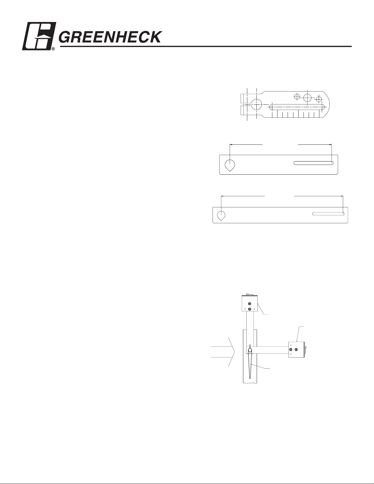
Small crankarm
Medium crankarm
Three (3) different crankarms may be used, depending on
damper size and magnitude of start open pressure. See figure 1.
The blades of this type damper exhibit a gradual “lift off” as
start-open pressure is reached. The operating point is not
sharply defined, as when a door suddenly opens. There is a wide
flow range where pressure is approximately constant.
Counterweight Set Procedure (Horizontal flow
only)
The counterbalance weights on a vertically mounted damper
(horizontal flow), must be adjusted first, if the airflow direction
is changed. This is covered by a separate procedure. Basically,
the damper is adjusted for easy operation (blade weight is just
counterbalanced) before the pressure set arms and weights are
added.
Pressure Setting Procedure
Position damper in the proper orientation and flow direction.
If a specific relief pressure is required, install a U-tube
manometer or other pressure measuring device in the duct work
to monitor the static pressure.
Large crankarm
Figure 1
Figure 2A Horizontal Flow
If damper flow direction must be changed in the field, loosen
fastener in pressure set crankarm and rotate arms to correct
position. See figures 2A, 2B and 2C for correct pressure set arm
orientation with damper blades closed.
Page 2
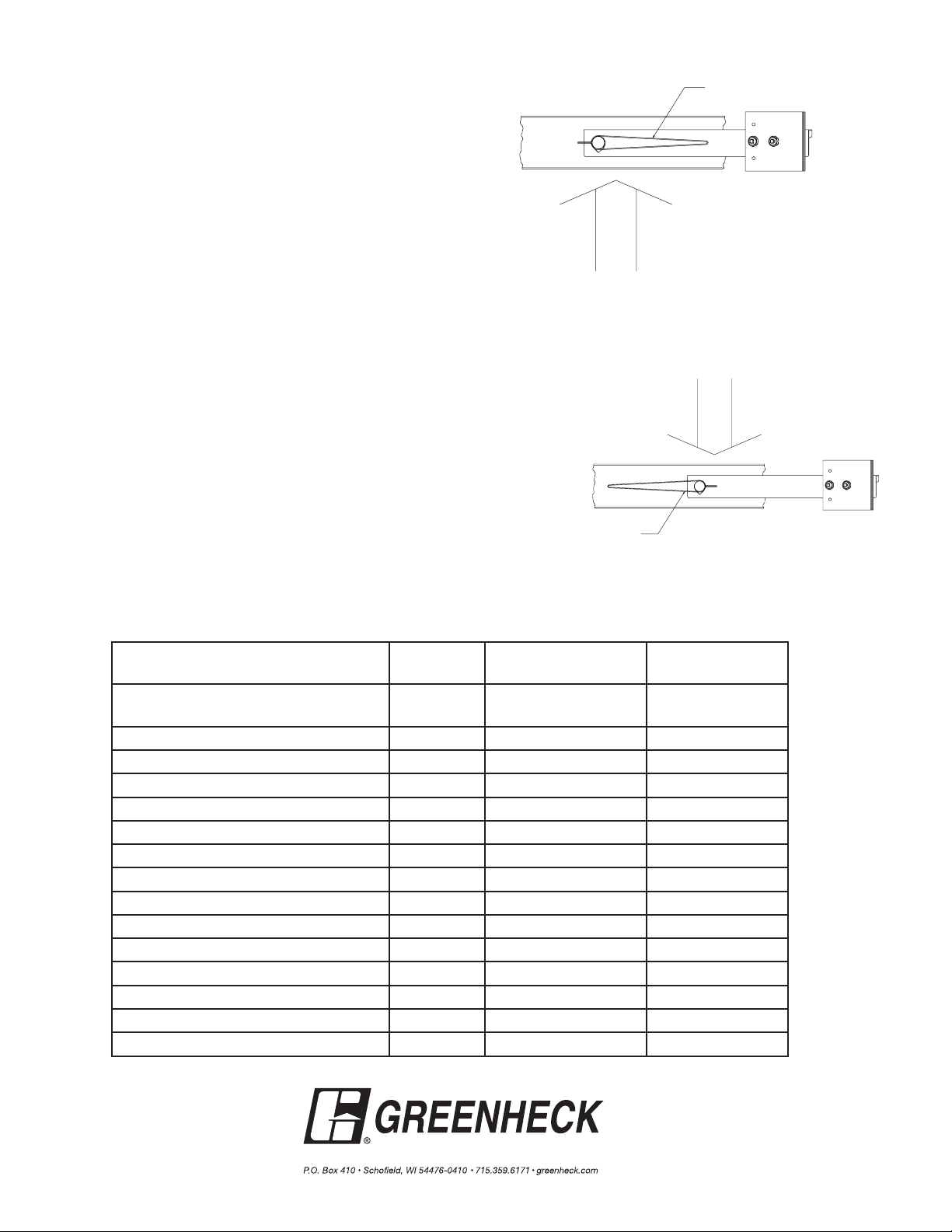
FLOW
DAMPER BLADE
Pressure Setting Procedure cont....
FLOW
DAMPER BLADE
Start-open pressure is adjusted by either changing weight
center distance from axle center line, or by increasing
or decreasing the quantity of plates mounted to arms.
In extreme cases, the arm length and quantity must be
changed. See table at the end of procedure for replacement
parts.
Adjust weight center distance first. Loosen fasteners
holding weight plates to arm and move inward or outward in
arm slot as required. Moving plates toward axle will reduce
start-open pressure; increasing the center distance will
increase the pressure at which blades start to open. If a
greater range of pressure set adjustment is required, add or
remove plates from arms as required to obtain the required
start-open pressure.
Check all fasteners for tightness.
Figure 2B Vertical Up Flow
Table of Components
Components Applicable
Axle adapter, 3/8” sq. to ¾” OD, 3”
long
Axle adapter, short, ¾” OD HPR-120 370120 416343
¾” crankarm All 653630 687738
3/8”-16 x 2 crankarm bolt All 415882 415924
3/8”-16 hex nut for crankarm All 415457 416168
Short counterweight arm (8½”) All 647344 689404
Long counterweight arm (12½”) All 657343 683951
3/8”-16 set screw for short/long arm All 415050 415763
3/8”-16 weld nut for short/long arm All 415127 415928
Counterweight plate, 1¼” x 3½” All 653144 687637
Counterweight plate, 2½” x 3½” All 653143 687636
Counterweight plate, 3½” x 3½” All 653142 687635
Bolt, ¼” - 20 x 1¼” All 415973 NA
Bolt, ¼” - 20 x 1½” All 415517 416103
Nut, ¼” - 20 All 415455 415575
Figure 2C Vertical Down Flow
Galvanized Part
Model
HPR-120 458959 NA
Number
Stainless Steel
Part Number
Copyright © 2006 Greenheck Corporation
469134 Adj. on Pressure Relief Dampers
Rev. 1 May 2006
 Loading...