


DOMIX 45A
Automatic Water Doser Mixer
Operator’s Manual
CODE 2600111 – 11.09.2001
Belshaw Bros., Inc.
1750 22nd Ave S.
Seattle, WA 98144
Phone: 206-322-5474
Fax: 206-322-5425
Toll Free: 1-800-578-2547
E-mail: service@belshaw.com http://www.belshaw.com
ENGLISH: |
p. 11 |
ESPAÑOL: |
p. 39 |
BY-PASS E.V. |
MAIN E.V. |
Y/G
|
|
blu grey |
brown blu |
|
|
G/Y |
|
|
|
egnaro |
BUZZER |
|
|
etihw |
|
|
|
|
|
|
|
teloiv |
|
|
|
der |
|
|
|
kcalb |
|
MAIN P.C.BOARD |
|
INT. PROBE |
POWER P.C.BOARD |
|
kcalb |
LITRE COUNTER |
SUPPLY |
|
|
|
|
|
egnaro |
|
|
|
|
|
PUMP |
EXT. PROBE |
|
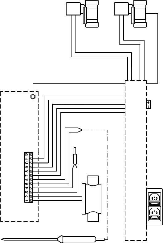
Figure –1: Schema elettrico – Internal layout |
|
|
|
DOMIX 45A – 2600111 – 11.09.2001 |
Diagrammi |
Boiler |
Rete |
Rete |
Refrigeratore |
||||||||||||
|
|
|
|
Cold water mains |
|||||||||||
|
|
|
|
Cold water mains |
Refrigerator |
||||||||||
|
|
|
|
Réseau |
|||||||||||
|
|
|
|
Réseau |
Réfrigérateur |
||||||||||
|
|
|
|
Kaltwasser-Anschluß |
|||||||||||
|
|
|
|
Kaltwasser |
Wasserkühler |
||||||||||
Caldera |
Cañería del agua fría |
||||||||||||||
C. del agua fría |
Refrigerador |
||||||||||||||
|
|
|
|
|
|
|
|
||||||||
|
|
|
|
|
|
|
|
|
|
|
|
|
|
|
|
|
|
|
|
|
|
|
|
|
|
|
|
|
|
|
|
|
|
|
|
|
|
|
|
|
|
|
|
|
|
|
|
|
|
|
|
|
|
|
|
|
|
|
|
|
|
|
|
|
|
|
|
|
|
|
|
|
|
|
|
|
|
|
|
|
|
|
|
|
|
|
|
|
|
|
|
|
|
|
|
|
|
|
|
|
|
|
|
|
|
|
|
|
|
|
|
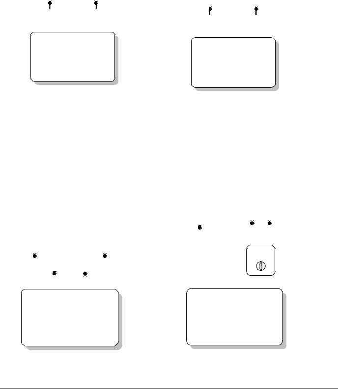
Figura 2
Caldera |
Rete waterCold mains Réseau Kaltwasser-Anschluß Cañeríadel agua fría |
|
|
|
Refrigerador |
||||||||||||||||||
Boiler |
|
|
|
|
|
|
|
|
|
|
|
|
|
|
|
|
|
Refrigeratore |
|||||
|
|
|
|
|
|
|
|
|
|
|
|
|
|
|
|
|
|
|
|
|
|
Refrigerator |
|
|
|
|
|
|
|
|
|
|
|
|
|
|
|
|
|
|
|
|
|
|
|
Réfrigérateur |
|
|
|
|
|
|
|
|
|
|
|
|
|
|
|
|
|
|
|
|
|
|
|
Wasserkühler |
|
|
|
|
|
|
|
|
|
|
|
|
|
|
|
|
|
|
|
|
|
|
|
|
|
|
|
|
|
|
|
|
|
|
|
|
|
|
|
|
|
|
|
|
|
|
|
|
|
|
|
|
|
|
|
|
|
|
|
|
|
|
|
|
|
|
|
|
|
|
|
|
|
|
|
|
|
|
|
|
|
|
|
|
|
|
|
|
|
|
|
|
|
|
|
|
|
|
|
|
|
|
|
|
|
|
|
|
|
|
|
|
|
|
|
|
|
|
|
|
|
|
|
|
|
|
|
|
|
|
|
|
|
|
|
|
|
|
|
|
|
|
|
|
|
Figura 4
Figura 3
Caldera |
Rete waterCold mains Réseau Kaltwasser-Anschluß Cañeríadel agua fría |
Refrigerador |
||||||||
Boiler |
|
|
|
|
Refrigeratore |
|||||
|
|
|
|
|
|
|
|
Refrigerator |
||
|
|
|
|
|
|
|
|
Réfrigérateur |
||
|
|
|
|
|
|
|
|
Wasserkühler |
||
|
|
|
|
|
|
|
|
|
|
|
|
|
|
|
|
|
|
|
|
|
|
|
|
|
|
|
|
|
|
|
|
|
|
|
|
|
|
|
|
|
|
|
|
|
|
|
|
|
|
|
|
|
|
|
|
|
|
|
|
|
|
|
|
|
|
|
|
|
|
|
|
|
|
|
|
|
|
|
|
|
|
|
|
|
|
|
|
|
|
|
|
|
|
|
|
|
|
|
Figura 5
DOMIX 45A –Schemi2600111di–collegamento11.09.2001 idraulico – Hydraulic connection examplesDiagrammi Schemas des raccordements hydrauliques – Ejemplos de conexión hidráulica
1 |
|
|
|
|
|
|
|
|
|
|
|
Warm(-er) |
|
|
|
|
|
Cold(-er) |
|
||
2 |
|
|
|
|
|
|
|
|
|
|
3 |
|
|
|
|
16 |
15 |
14 |
|
|
|
|
|
|
|
|
|
|
|
|
|
|
4 |
|
|
|
|
|
|
|
|
|
|
5 |
35 |
30 |
17 |
|
|
|
|
|
|
|
|
40 |
|
25 |
|
|
|
MANUAL |
PROG. |
BYPASS |
RUN |
|
|
|
|
|
|
|
|
|
||
|
45 |
|
20 |
12 |
|
|
|
|
|
|
|
|
|
|
|
|
|
|
|
||
|
50 |
|
15 |
7 |
|
|
|
|
|
|
|
55 |
|
10 |
|
|
|
|
|
|
|
|
|
|
5 |
|
|
|
|
|
|
|
6 |
|
|
|
|
|
|
|
|
|
|
|
7 |
|
|
8 |
9 |
|
10 |
11 |
|
|
13 |
 12
12
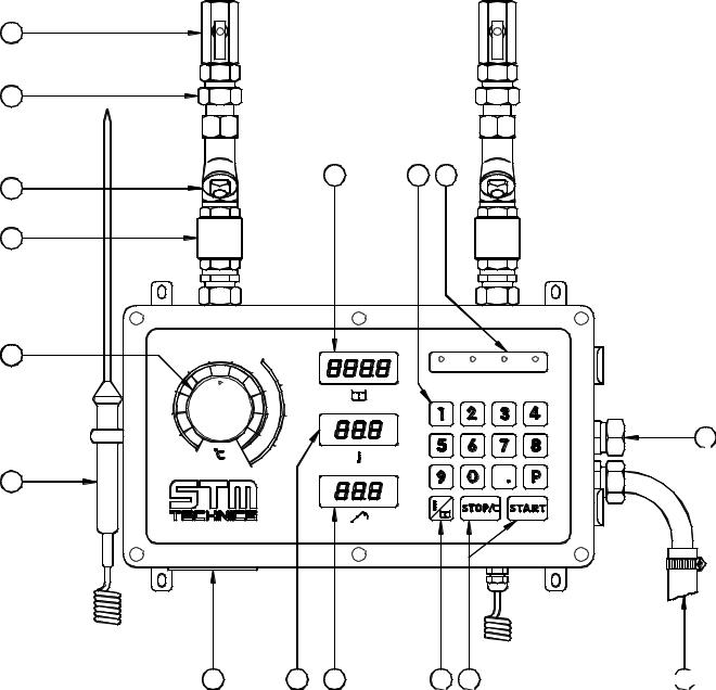
Figure –6
Schema rappresentativo della macchina – Machine Overview
DOMIX 45A – 2600111 – 11.09.2001 |
Diagrammi |

2 |
5 |
1 |
|
|
9 |
|
|
|
|
|
|
|
|
|
8 |
|
|
BY |
|
|
|
|
|
PROG. |
|
|
7 |
21 |
|
MANUAL |
|
|
|
|
|
|
|
|
6 |
11 |
01 |
12 |
7 |
|
5 |
|
17 |
20 |
15 |
10 |
|
|
|
25 |
|
|
|
|
30 |
|
|
|
4 |
|
35 |
|
|
|
|
|
|
40 |
|
|
|
|
|
45 |
50 |
55 |
|
|
|
|
|
|
3 |
Figura –7
Figure –7: Spaccato della macchina con i ricambi – Overview with spare parts
DOMIX 45A – 2600111 – 11.09.2001 |
Diagrammi |
1. DESCRIPTION
(see figure no. 6)
1.Ball gate valves
2."O" ring gasket type unions to facilitate installation
3.Stainless steel double mesh filters for water impurities
4.Non return valves
5.Temperature regulation knob
6.External probe
7.Supply plug with fuse and spare and plug for the pump control, with fuse and spare
8.Display for the internal electronic thermometer and the set temperature
9.Display for the external electronic thermometer and the programs
10. key to move from temperature to quantity and vice versa
11.STOP/C and START keys
12.Delivery hose
13.By-passs connection
14.Series of function control lights
15.Membrane keyboard for the data entry
16.Display showing litres selected, litres still to be delivered (during the dosing), or already delivered (after pressing STOP).
1.1 TECHNICAL FEATURES
SOFTWARE Version: DOMIX45.02g
The Domix 45A features are listed in the Table 1.
|
Supply tension |
230Volt A.C. or 110Volt A.C. ± 10% |
|
|
(see equipment rating plate) |
|
|
|
Frequency |
50/60Hz |
|
|
Power |
25VA |
|
|
Hydraulic connections |
½” |
|
|
By-pass water outlet |
16mm |
|
|
Max. inlet water temperature |
65oC |
|
|
Inlet water pressures |
max.: 5bar |
|
|
|
min.: 1bar |
|
|
|
Max. pressure ratio between the 2 inlets: 1:5 |
|
|
Temperature control |
Setting range: 2 ÷ 60oC |
|
|
|
Measure precision: 0,3oC |
|
|
|
Mixing precision: 1 oC |
|
|
Dosing control |
Max. dosage quantity: 999,9l (or 99,99l)* |
|
|
|
Min. dosage quantity: 100g (or 10g) * |
|
|
|
Precision: 1% (over 0,5l) |
|
|
|
*Microdomix, using the second decimal fig. |
|
|
Water delivery |
at 1bar and 20°C: 18litres/min |
|
|
|
at 5bar and 20°C: 40litres/min |
|
|
Supply fuse |
250V – 630mA delayed |
|
|
Pump remote control fuse |
250V 6,3A delayed |
|
|
|
Table 1 |
|
|
|
|
|
|
DOMIX 45A – 2600111 – 11.09.2001 |
1 |
|
2.INSTALLATION
In case of hard water (with high lime-scale content = hardness in French degrees higher than 25 – 30, or 250 ÷ 300ppm) it is necessary to employ an ion exchange water softener. This unit must be calibrated so as to maintain a residual hardness ranging between 5 and 10 French degrees (50 ÷ 100ppm). The use of electronic water softeners is not advised, since their efficacy has not been proved yet.
Fix the doser-mixer on the wall at a height from the floor of 1350 ÷ 1550mm, using the four wall plugs supplied. The90° wall plug hook is supplied to provide support for the water delivery outlet elbow.
Do not place other machines below the DOSER – MIXER.
Arrange the water inlet tubing as shown in the lay-out diagrams, figures 2 – 3 – 4 – 5, mounting the ball gate valves (1) at the end of the pipes (black lever = cold on the right and red lever = warm on the left).
With reference to the figure 4, it is advisable to use the pre-assembled group: Three way connection kit, code 3801205.
With reference to the fig. 5, the use of Automatic kit is foreseen, code 3801231 (230V).
Connect ball gate valves to the doser-mixer by means of the "O" ring gasket type unions (2).
Insert the delivery hose (12) into its housing.
Connect the by-pass (13) to a drain by means of a copper pipe with 16mm external diameter.
Connect to the proper power supply (see equipment rating plate near the plug 7), monophase 50 or 60Hz, using the supplied flying socket, fitted with a three core cable min. section 3x1mm². An external switch is helpful.
For the eventual pump remote control, use the supplied flying socket to connect the remote control switch of the pump(s). The use of such a pump is necessary when one of the two inlet pressures is less than 1 bar, for example when using unpressurized water heaters or refrigerators.
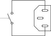
The plug on the device has the following wiring diagram (clean contact):
MAX 3A resistive
Figure – 8
DOMIX 45 A – 2600111 – 11.09.2001 |
2 |
 Loading...