

Page 1

DOMIX 45A
Automatic Water Doser Mixer
ENGLISH: p. 11
ESPAÑOL: p. 39
Operator’s Manual
CODE 2600111 – 11.09.2001
Belshaw Bros., Inc.
1750 22
Seattle, WA 98144
Phone: 206-322-5474
Fax: 206-322-5425
Toll Free: 1-800-578-2547
E-mail: service@belshaw.com
http://www.belshaw.com
nd
Ave S.
Page 2

Page 3

S
S
.
A
V
.
P
-
E
Y
B
.
N
I
V
.
A
E
M
n
u
w
y
u
l
e
r
b
g
l
o
b
r
b
G
/
Y
G
/
Y
a
n
r
g
e
o
h
i
t
e
w
t
e
l
v
i
o
d
e
r
k
a
c
l
b
R
E
Z
Z
U
B
E
.
B
T
O
N
I
R
P
D
R
A
N
I
O
A
B
.
M
C
.
P
R
E
T
k
a
c
b
l
n
g
e
a
r
o
E
R
N
T
I
U
L
O
C
R
E
W
O
P
D
R
A
O
B
.
C
.
P
Y
L
P
P
U
S
P
M
U
P
Figure –1: Schema elettrico – Internal layout
E
.
B
T
O
X
E
R
P
DOMIX 45A – 2600111 – 11.09.2001 Diagrammi
Page 4

g
Boiler Rete
Cold water mains
Réseau
Kaltwasser-Anschluß
Caldera Cañería del agua fría
Rete Refrigeratore
Cold water mains Refrigerator
Réseau Réfrigérateur
Kaltwasser Wasserkühler
C. del agua fría Refrigerador
Figura 2
Fi
ura 3
Boiler Refrigeratore
Wasserkühler
Caldera Refrigerador
Cold water mains
Rete
Kaltwasser-Anschluß
Réseau
Refrigerator
Réfrigérateur
Cañería del agua fría
Boiler Refrigeratore
Refrigerator
Réfrigérateur
Wasserkühler
Caldera Refrigerador
Rete
Cold water mains
Réseau
Kaltwasser-Anschluß
Cañería del agua fría
DOMIX 45A – 2600111 – 11.09.2001 Diagrammi
Schemas des raccordements hydrauliques – Ejemplos de conexión hidráulica
Figura 4
Schemi di collegamento idraulico – Hydraulic connection examples
Page 5
1
2
3
4
5
6
Warm(-er) Cold(-er)
141516
17
30
35
40
45
50
55
25
12
20
15
7
10
5
MANUAL PROG. RUNBY- PASS
13
7
8 9 10 11 12
Figure –6
Schema rappresentativo della macchina – Machine Overview
DOMIX 45A – 2600111 – 11.09.2001 Diagrammi
Page 6

2
5
1
9
Y
B
.
G
O
R
P
L
A
U
N
A
12
M
6487
2
7
11
10
1
0
7
2
1
5
2
0
3
5
3
0
4
5
4
5
5
1
0
1
5
5
0
5
3
Figura –7
Figure –7: Spaccato della macchina con i ricambi – Overview with spare parts
DOMIX 45A – 2600111 – 11.09.2001 Diagrammi
Page 7

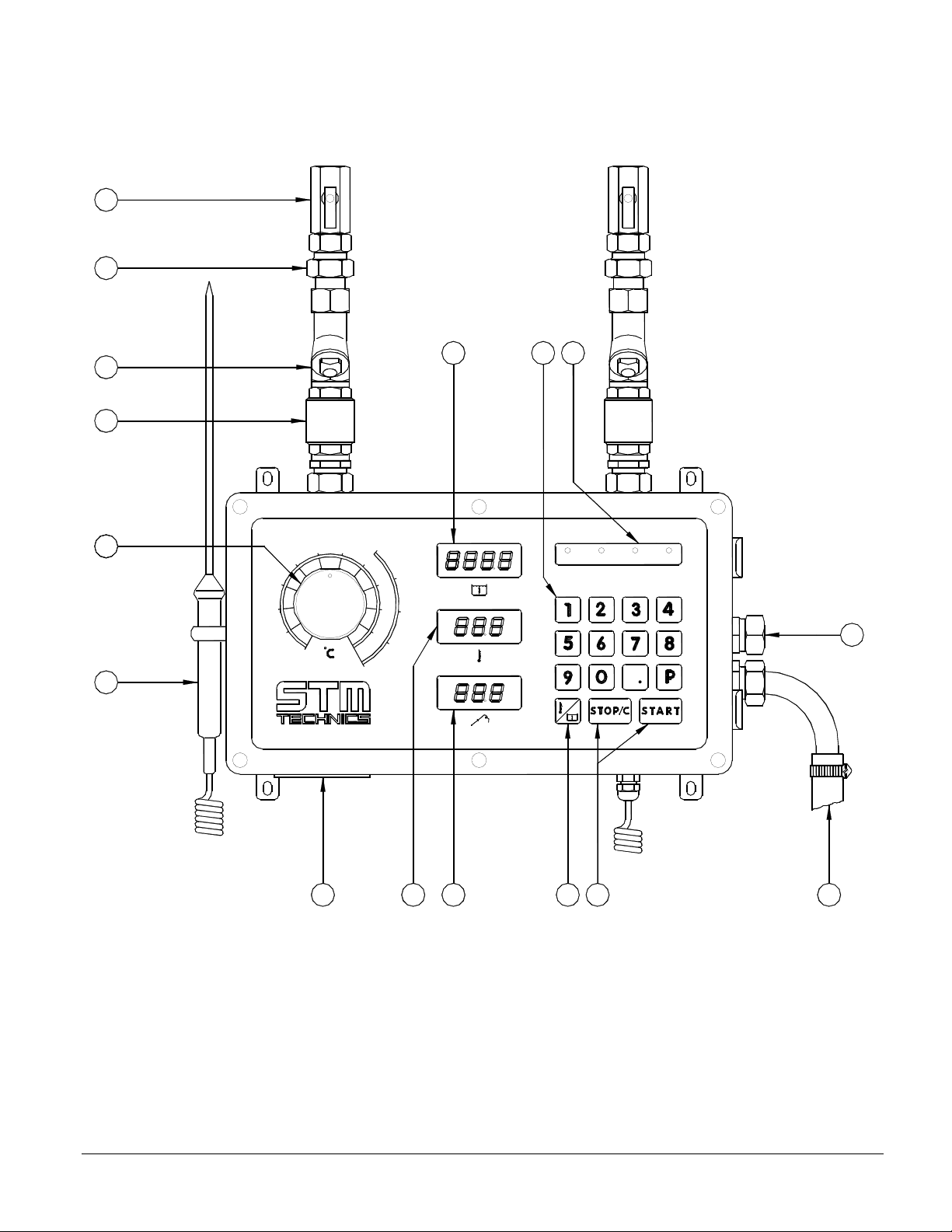
1. DESCRIPTION
(see figure no. 6)
1. Ball gate valves
2. "O" ring gasket type unions to facilitate installation
3. Stainless steel double mesh filters for water impurities
4. Non return v alves
5. Temperature regulation knob
6. External probe
7. Supply plug with fuse and spare and plug for the pump control, with fuse and spare
8. Display for the internal electronic thermometer and the set temperature
9. Display for the external electronic thermometer and the programs
10. key to move from temperature to quantity and vice versa
11. STOP/C and START keys
12. Delivery hose
13. By-passs connection
14. Series of function control lights
15. Membrane keyboard for the data entry
16. Display showing litres selected, litres still to be delivered (during the dosing), or already
delivered (after pressing STOP).
1.1 TECHNICAL FEATURES
SOFTWARE Version: DOMIX45.02g
The Domix 45A features are listed in the Table 1.
Supply tension
(see equipment rating plate)
Frequency 50/60Hz
Power 25VA
Hydraulic connections
By-pass water outlet 16mm
Max. inlet water temperature 65oC
Inlet water pressures max.: 5bar
Temperature control Setting range: 2 ÷ 60oC
Measure precision: 0,3oC
Mixing precision: 1 oC
Dosing control Max. dosage quantity: 999,9l (or 99,99l)*
Water delivery
Supply fuse
Pump remote control fuse
230Volt A.C. or 110Volt A.C. ± 10%
½”
min.: 1bar
Max. pressure ratio between the 2 inlets: 1:5
Min. dosage quantity: 100g (or 10g) *
Precision: 1% (over 0,5l)
*Microdomix, using the second decimal fig.
at 1bar and 20°C: 18litres/min
at 5bar and 20°C: 40litres/min
250V – 630mA delayed
250V 6,3A delayed
Table 1
DOMIX 45A – 2600111 – 11.09.2001
1
Page 8

2. INSTALLATION
In case of hard water (with high lime-scale content = hardness in French degrees higher
than 25 – 30, or 250 ÷ 300ppm) it is necessary to employ an ion exchange water softener.
This unit must be calibrated so as to maintain a residual hardness rangin g between 5 and 10
French degrees (50 ÷ 100ppm). The use of electronic water softeners is not advised, since
their efficacy has not been proved yet.
Fix the doser-mixer on the wall at a height from the floor of 1350 ÷ 1550mm, usi ng the four
wall plugs supplied. The90° wall plug hook is supplied to provide support for the water
delivery outlet elbow.
Do not place other machines below the DOSER – MIXER.
Arrange the water inlet tubing as shown in the lay-out diagrams, figures 2 – 3 – 4 – 5,
mounting the ball gate valves (1) at the end of the pipes (black lever = cold on the right
and red lever = warm on the left).
With reference to the figure 4, it is advisable to use the pre-assembled group: Three way
connection kit, code 3801205.
With reference to the fig. 5, the use of Automatic kit is foreseen, code 3801231 (230V).
Connect ball gate valves to the doser-mixer by means of the "O" ring gasket type unions (2).
Insert the delivery hose (12) into its housing.
Connect the by-pass (13) to a drain by means of a copper pipe with 16mm external
diameter.
Connect to the proper power supply (see equipment rating plate near the plug 7),
monophase 50 or 60Hz, using the supplied flying socket, fitted with a three core cable min.
section 3x1mm². An external switch is helpful.
For the eventual pump remote control, use the supplied flying socket to connect the
remote control switch of the pump(s). The use of such a pump is necessary when one of the
two inlet pressures is less than 1 bar, for example when usi ng unpressurized water heaters or
refrigerators.
The plug on the device has the following wiring diagram (clean contact):
Figure – 8
MAX 3A resistive
DOMIX 45 A – 2600111 – 11.09.2001
2
Page 9

3. OPERATING INSTRUCTIONS
Switch on the doser-mixer using the external switch (or by plugging in the flying socket).
The first displays appearing at the switching on refer to the self-test. The displays show the
numbers from 0 to 9, the microprocessor software version, then the data regarding the last
discharge.
3.1 MANUAL OPERATION
Press P00 on the keyboard (the yellow Manual led lights up and the decimal point of the
litres flashes), then select the required water quantity. For batches lower than 0,5 litres, it is
helpful to operate with two decimal figures, in order to improve the device precision
(MICRODOMIX function), e.g. it is possible to select 1,65l instead of 1,6l: the decimal point
shifts automatically to the following position. To store the temperature, press the key: the
flashing shifts to the decimal point of the temperature, which can be set.
In case of error, in the quantity or in the temperature, press the STOP/C key and reselect.
Press the START key:
- the by-pass electrovalve opens and the relevant control light lights up
- the display (8) shows the actual discharge t e mperature
If necessary, adjust the temperature by the regulating knob (5), so that it coincides with the
stored temperature. In case of correction, wait a few seconds before adjusting again, in
order to let the temperature stabilize.
As soon as the temperature reaches the set value (with the allowed tolerance), the by-pass
electrovalve closes, the dosing electrovalve opens and the RUN pilot light lights up.
The quantity display shows the litres still to be delivered (count-down), the central display
indicates the discharge temperature and the lower one measures the external probe
temperature.
If, for external reasons, the temperature exceeds the allowed tolerance range, the dosing
automatically stops and the device returns to by-pass. If the temperature is quickly adjusted,
the dosing restarts after 3 seconds, otherwise there is the signalling of not correct
temperature (see point 3.5.1), after 12 ÷ 15 seconds.
To manually stop water delivery at any time press the STOP/C key. In the display (16) the
quantity of delivered water flashes; to stop the dosage, press again the START key; pressing
again the STOP/C key the memory is cancelled and the desired quantity can be set.
To obtain the same water dosage in successive operations, simply press the START key, as
the doser-mixer is provided with a memory. In the case of power failure during dosing t he
data are not lost; when power is restored simply repress the START key to complete the
dosing operation (see par. 3.5.3).
To ensure optimum operation the warm water temperature must be at least 10°C higher
than the required delivery water temperature and the cold water should be at least 3°C
lower. Low temperatures (under 10° – 15°C) may be obtained only using a refrigerator.
DOMIX 45 A – 2600111 – 11.09.2001
3
Page 10

NOTE: The stored temperature is continuously visualized till START is pressed, after that the
discharge temperature appears.
3.2 OPERATION WITH 80 PROGRAMS
3.2.1
Initial recipes setting
Set the program No. (ex. P01 then P02 etc.) appearing on the lower display (9) (PROGR. lights
up) and then the desired water quantity, appearing on the upper display (16).
To store the temperature, press the key and proceed as for manual operation.
It is possible to exit from a recipe setting dosing the recipe itself (press START), setting a new
recipe (press P...), or automatically after 10 seconds: in all these cases the recipe is stored.
Warning: recipe numbers from 1 to 9 must be always set using the format: 01, 02, etc..
3.2.2 With recipes already programmed:
To recall a recipe, enter the desired No. (for example P28), which i s shown for 3" on the lower
display (9), while the upper displays show the relevant quantity and temperature.
Press START to carry out the dosing. If modifications are required, set the new quantity and/or
temperature as explained above.
To stop water delivery manually at any time press the STOP/C key. After that on the display (16)
the delivered water quantity flashes; to resume dosing press again the START key, otherwise,
pressing the STOP/C key, the quantity is cleared and it is possible to set a new quantity. To
modify the temperature, press and proceed as already described.
3.3 USE OF EXTERNAL PROBE
The equipment is fitted with an auxiliary precision electronic thermometer with a mobile probe
(6), usable at distances up to 5 metres.
Temperature readout on the display (9) is continuous, except if the program No. appears.
3.4 SPECIAL FUNCTIONS
With the double pression of the P key, the device shows the succession of the recipes st ored
in memory.
3
Holding the key for 10", the total amount of the m
decimal number) is indicated: see example in Figure 9.
delivered by the machine (with a
DOMIX 45 A – 2600111 – 11.09.2001
2 4 5. 7
t o t
M E M
Figure -9
4
Page 11

By pressing the STOP/C key, it will appear the number of times, divided into 10, that the dosing
electrovalve (central display) and the by-pass electrovalve (lower display) hav e been opened
(see fig. 10).
E L. U
2 0 3
2 0 7
Figure -10
Pressing again the STOP/C key, the normal visualization is restored.
NOTE: The totalizators go automatically to zero when they reach respectively 999,9m3 and 9990
times (visualized: 999).
To prevent from modifying the recipes, it is possible to protect the setting and modification
operations, pressing the P key for 5 seconds; the display indicates the wording as in Figure
11, in which the code 147 has to be entered.
C o d E
P r G
Figure -11
Then, pressing the P key, the display indicates the wording as in Figure 12:
r E c i
A b i
DOMIX 45 A – 2600111 – 11.09.2001
Figure -12
5
Page 12

Pressing the 1 key, the wording diS appears, indicating that the recipe programming is disabled;
pressing the 2 key, the wording Abi appears, indicating that the recipe programming is
enabled.
Pressing P the normal visualization is restored.
Free delivery: it is possible to exclude the litre-counter counting (for example in case of
malfunction of the part) by means of the special program P99:
F r E E
2 3. 5
2 1. 8
Figure -13
With the START and STOP keys the electrovalve opens and closes.
3.5 ERROR MESSAGES AND CORRECTIVE ACTIONS
All error messages are accompanied by flashing wordings and an intermittent acoustic
signalling. The latter one can be stopped with the STOP key. Using the START key the error
message is cancelled and the delivery starts again. On the contrary, the double STOP
command cancels the delivery. The possible error messages and relevant wordings are listed
here below.
3.5.1 Unreachable temperature
With the by-pass electrovalve open, if the temperature stabilizes at a value outside of the
allowed tolerance range, after 30 seconds the following menu appears:
ÑtE M PÒ
n o t
c o r
Figure -14
Possible causes:
A) The regulation of the temperature by means of the knob is not correct. Regulate the
temperature.
B) The regulating knob is at one limit stop, but it is not enough to reach the set temperature
value. Check that the water is at least 10°C warmer than the requested value (if the knob is
DOMIX 45 A – 2600111 – 11.09.2001
6
Page 13

at the warm stop limit), or 3°C colder (on the cold stop limit), as required for a good
operation of the mixer (see page 16, bottom par.).
3.5.2 Quantity counting error
After pressing START, after around 12 seconds this wording appears:
ÑEr r.LÒ
2 3. 5
2 1. 7
Figure -15
Possible causes:
A) If no water comes out of the device:
The taps on the inlets of warm water and/or cold water are not open. Check that both
are open and that the connection to the pipes is correct.
The inlet filters are obstructed. Clean them.
The electrovalve does not open. Contact the Service.
B) If water comes out normally and this message appears, it indicates a malfunction of the
litre-counter. Contact the Service.
3.5.3 Probe error
The PrE wor ding appears on the display referred to the damaged or wrongly connected probe .
Contact the Service for replacement. If the external probe is damaged, the wording appears,
but the machine works properly. On the contrary, if the internal probe is damaged, the by-pass
is controlled for a few seconds, then it shifts automatically to the dosing: the by-pass
thermostatic control is excluded. Use the external probe to check that the temperature is
correct.
3.5.4 Tension fall
If there is a tension fall during a water delivery, the device stores the delivered quantity and
interrupts the delivery. When tension is restored, the following wording appears:
Press START to complete the dosage.
DOMIX 45 A – 2600111 – 11.09.2001
ÑtE n SÒ
F A I
2 1. 7
Figure -16
7
Page 14

3.5.5 Parameter error
If, after the machine switching on, the following message appears on the display:
ÑrA MÒ
d E F
Figure -17
some incongruous values have been found in the machine parameters.
Contact the Service for further information.
It is anyway possible to restart the machine with the standard settings:
Press contemporaneously the 3 and 7 keys for 5 seconds: the device rest ores the default values
and restarts automatically. While holding the keys, the display shows th e menu of figure 18 and
indicates that the standard values are being setting.
d o M
A U t
Figure –18
3.6 OPERATION INTERRUPTION
If, with tension available, all displays remain off, it means that electrical supply does not reach
the main board, or this latter is damaged.
Possible causes:
A) Overtension and/or supply fuse failure. Open the fuse housing next to the supply plug, take
out the spare fuse and replace the damaged one.
B) Damage to the actuators board or the main board. Contact the Service.
DOMIX 45 A – 2600111 – 11.09.2001
8
Page 15

4. MAINTENANCE INSTRUCTIONS
To assure a long working life of the internal parts of the device, following periodic checks are
necessary:
1. Clean the filters (3) regularly, particularly if water has a high lime-scale content.
2. When switching off the doser-mixer, always set the temperature regulation knob (5) to its mid
position, to allow a minimum number of moves in the mixer valve, particularly when deliveries
at the same temperature are carried out.
3. To clean the external surface of the doser-mixer, use a soft sponge and water or a neutral
detergent; for more resistant grime, use alcohol or turpentine.
4.1 SPARE PARTS
Figure-7 on shows the machine overview indicating the various components of the device and
Table 2 lists their description with relevant spare parts code numbers .
POS. DESCRIPTION CODE – 230V VARIANTS – 110V
1 Cover with keyboard and electronics 3811032 --2 Regulation knob 3801208 --3 External temperature probe 3812511 --4 Actuators and supply board 3811534 3811537
5 Thermostatic element 4300105 --6 2 wire litre-counter 3801007 --7 Internal temperature probe 3812522 --8 Electrovalve assembly with coil 3801127 3801129
9 Coil for electrovalve 4400404 4400406
10 Filter - no return valve assembly 3801230 --11 Hot water ball gate valve (red, left) 3801229 ---
--- Internal electrovalve group 4400451 ---
--- Supply flying socket 4400606 ---
--- Pump remote control flying socket 4400608 ---
--- Delivery hose Ø 16mm 3801209 ---
Table 2
DOMIX 45 A – 2600111 – 11.09.2001
9
Page 16

1. DESCRIPCION
(véase fígura nr. 6 p. 3)
1. Cierres metálicos de bola
2. Boquillas O-R para facilitar la instalación
3. Filtros para las impuridades con doble red inox
4. Válvulas de no retorno
5. Regulador de la temperatura
6. Sonda externa
7. Enchufe de alimentación con fusi ble y repuesto y enchufe para el control de una bomba,
con fusible y repuesto
8. Display del termómetro electrónico interno y de la temperatura seleccionada
9. Display del t ermómetro electrónico externo y de los programas
10. Tecla para pasar de la temperatura a la cantidad y vicerversa
11. Teclas STOP/C y START
12. Tubo para descarga
13. Empalme de by-pass
14. Serie de avisadores ópticos
15. Teclado a membrana para seleccionar los datos
16. Display de los litros programados, todavia por descargar (durante la dosificación) o bién ya
descargados (después de haber apretado STOP).
1.1 CARACTERISTICAS TECNICAS
Software: DOMIX45.02f
Las características del Domix 45A están indicadas en el prospecto 1.
Tensión de alimentación
(véase plaquita sobre el aparato)
Frecuencia de red 50/60Hz
Potencia absorbida 25VA
Empalmes hidráulicos
Descarga agua de by-pass 16mm
Temperatura máx. del agua a la entrada 65oC
Presiones de entrada Máx.: 5bar
Control de la temperatura Campo de regulación: 2 ÷ 60oC
Precisión en la medida: 0,3oC
Precisión en la mezcla: 1oC
Control de la dosificación Dosificación máxima: 999,9l (o 99,99l)*
Capacidad agua
Fusible de alimentación
Fusible del telemando bomba
230Volt c.a. o 110Volt c.a. ± 10%
½”
Min.: 1bar
Difer de presión máx entre las entradas: 1:5
Dosificación mínima: 100g (o 10g)*
Precisión: 1% (sobre 0,5l)
*Microdomix, empleo de la 2° cifra decimal
a 1bar y 20°C: 18litros/min
a 5bar y 20°C: 40litros/min
250V – 630mA retardado
250V – 6,3A retardado
Prospecto 1
DOMIX 45 A – 2600111 – 11.09.2001
10
Page 17

2. INSTALACION
En el caso de agua dura (con elevado contenido de sales de calcio = dureza en grados
franceses superior a los 25 ÷ 30, o bien 250 ÷ 300ppm) es practicamente indispensable el
empleo de un ablandador del agua por intercambio de iones. Este aparato debe de
utilizarse para mantener la dureza residual entre 5 y 10grados franceses (50 ÷ 100ppm). No
se aconseja el empleo de ablandadores de agua del tipo electrónico puesto que su
eficacia no ha sido probada todavia.
Fijar el Dosificador-Mezclador a la pared a una altura de 1350 ÷ 1550mm, utilizando los 4
apropiados ganchos incluídos. El gancho de 90°, del cual también se completa el aparato,
sirve como soporte para fijar a la pared la curva de suministro del agua.
No montar otra maquina bajo el aparato.
Preparar los tubos de llegada del agua (véanse indicaciones contenidas en uno de los
esquemas 2 – 3 – 4 – 5, colocando en su parte final los cierres metálicos (1) (indicador negro
= agua fría, a la derecha e indicador rojo = agua caliente, a la izquierda).
Si se siguen las indicaciones contenidas en el esquema 4, aconsejamos el empleo del
apropiado grupo, ya montado: kit tres vías, código 3801205.
En el caso del esquema 5, se aconseja el empleo del kit automatico, código 3801231.
Conectar hidráulicamente el aparato con las bocas de los tubos (2).
Introducir el tubo de dosificación (12) en su sitio.
Conectar el by-pass (13) con la descarga, utilizando un tubo en cobre del © externo de
16mm.
Alimentar con la correcta tensión (véase plaquita informativa fijada al lado del enchufe 7),
monofásica 50 o 60Hz, por medio de la toma volante i ncluida, que debe conectarse con
cable tripolar de una sección mínima 3 x 1mm². Se aconseja preveer un interruptor externo.
Para el eventual mando remoto de la bomba, utilizar la apropiada toma de ali mentación
del teleruptor de la bomba, o bién de las bombas. El empleo de la bomba es indispensable
cuando una de las dos presiones en entrada es inferior a 1 bar, como por ejemplo en el
caso de calentadores o refrigeradores sin presión.
El enchufe tiene el siguiente esquema eléctrico (contacto limpio):
Figura – 8
MAX 3A resistive
DOMIX 45 A – 2600111 – 11.09.2001
11
Page 18

3. INSTRUCCIONES PARA EL USO
Proporcionar tensión al aparato mediante el interruptor externo, o insertando la toma volante.
Los displays que aparecen al encender el aparato se refieren al autodiagnósis. Los displays
visualizan los números en secuencia de 0 a 9, luego la versión del software del microprocesor,
pues aparecen los datos relativos a la última descarga efectuada.
3.1 FUNCIONAMIENTO MANUAL
Programar en el teclado P00 (luce el led amarillo Manual y el punto decimal de los litros
parpadea) y la cantidad de agua necesitada. Para dosificaciones inferiores a 5 l es útil
explotar la posibilidad de emplear dos cifras decimales, para mejorar la precisión de la
máquina (función MICRODOMIX). Por ejemplo, es posible seleccionar 1,65l en lugar de 1,6l:
el punto decimal se mueve automáticamente de una posición.
Para memorizar la temperatura, apretar la tecla : el punto decimal de la temperatura
parpadea, y es posible programarla.
Al cometer un error, sea en los litros sea en la temperatura, apretar la tecla STOP/C y volver
a programar.
Apretar la tecla START:
- la electroválvula de by-pass se abre y luce el relativo avisador óptico
- el display (8) indica la temperatura a la descarga
Si necesario, por medio del mando de regulación (5), ajustar la temperatura hasta que
coincida con la memorizada. En caso de corrección, esperar unos instantes antes de
intervenir de nuevo, para que la temperatura se establezca.
En cuanto la temperatura alcanza el valor seleccionado (con la tolerancia admitida), la
electroválvula de by-pass cierra, la electroválvula de dosifi cación se abre y luce el relativ o
avisador óptico RUN.
En el display de la cantidad aparece la cantidad todavía a suministrar (conteo
decreciente), en el display central aparece la temperatura a la descarga y en el inferior la
temperatura a la sonda externa.
Si por razones externas la temperatura sale del campo de tolerancia admitido, la
dosificación se interrompe automáticamente y el aparato vuelve al funcionamiento en bypass. Si la temperatura se ajusta rápidamente, se vuelve a la dosificación después de hacia
3 segundos que se ha vuelto al valor correcto, en caso contrario aparece la señalación de
temperatura no correcta (véase § 3.5.1).
En cualquier momento es posible interrumpir manualmente el suministro de agua
apretando la tecla STOP/C: en el display (16) parpadea la cantidad de agua ya
suministrada; para terminar la dosificación es sufi ciente apretar de nuevo la tecla START, en
caso contrario, apretando de nuevo la tecla STOP/C, se repone a cero la memoria y se
vuelve a programar la cantidad deseada.
Para todas sucesivas dosificaciones iguales, es sufi ciente apretar la tecla START, ya que el
aparato está dotato de memoria. Aún faltando la tensión durante la dosificación, los datos
en memoria no serán borrados: al regresar la tensión será suficiente apretar de nuevo la
tecla START para completar regularmente el suministro (véase § 3.5.4).
DOMIX 45 A – 2600111 – 11.09.2001
12
Page 19

Para lograr las mejores condiciones de funcionamiento, el agua caliente debe de tener
una temperatura de por lo menos 10°C superior a la temperatura deseada y el agua fría
por lo menos 5°C inferior. Las bajas temperaturas (debajo de los 10°-15°C) se obtienen sólo
mediante un refrigerador.
NOTAS
La temperatura memorizada queda visualizada hasta que se apriete START, después en el
display aparece la temperatura a la descarga.
3.2 FUNCIONAMIENTO CON 80 PROGRAMAS
3.2.1
Con recetas a programarse por primera vez
Seleccionar el nr de programa (ej. P01 pues P02 etc.) que aparece sobre el display inferior (9)
(se encende PROGR.) y luego la cantidad de agua deseada, que aparece sobre el display
superior (16).
Para memorizar también la temperatura, apretar y continuar como por el funcionamiento
manual.
De la programación de una receta es posible salir dosificando la receta misma (apretar START),
o seleccionando otra distinta receta (apretar P...), o automáticamente después de 10
segundos: en todos casos la receta queda ya memorizada.
Advertencia: los números de las recetas inferiores al 10 (por ejemplo: 1, 2 et c.) tienen que ser
seleccionados de esta manera: 01, 02, etc.
3.2.2 Con recetas ya programadas
Para utilizar una receta ya programada, seleccionar el número deseado (por ejemplo P 28)
que aparecerá por 3 segundos sobre el display inferior (9), mientras sobre los displays superiores
aparecerán la cantidad y la temperatura.
Para efectuar la dosificación, apretar START.
Para efectuar una modificación, programar directamente las nuevas cantidad y/o
temperatura, según ya explicado.
En cualquier momento se puede interrumpir manualmente el suministro con sólo apretar la
tecla STOP/C: en el display (16) parpadea la cantidad de agua ya sumini strada; para terminar
la dosificación es suficiente apretar de nuevo la tecla START; en caso contrario, apretar de
nuevo la tecla STOP/C para borrar la receta, y seleccionar la nueva receta. Para modificar la
temperatura, apretar la tecla y proceder según dicho.
3.3 USO DE LA SONDA EXTERNA
El aparato está completo de un termometro electrónico de pre cisión auxiliar con sonda móvil
(6) funcionante hasta 5 metros de distancia.
La temperatura se puede leer en continuo sobre el display (9), excepto cuando aparece el
número de programa.
3.4 FUNCIONES ESPECIALES
Con la doble presión de la tecla P, el aparato visualiza en sucesión todas las recetas
programadas.
DOMIX 45 A – 2600111 – 11.09.2001
13
Page 20

Apretando la tecla por 10", aparece el totalizador de m3 descargados por el aparato (con
una cifra decimal): véase el ejemplo en Figura 9.
2 4 5. 7
t o t
M E M
Figura -9
Apretando sucesivamente la tecla STOP/C aparece el número de veces que la electroválvula
ha sido abierta (véase fig. 10), dividido por 10.
E L. U
2 0 3
Figura -10
Apretando otra vez la tecla STOP/C se vuelve a la visualización normal.
NOTA:Los totalizatores se ponen automáticamente a cero cuando alcanzan respectivamente
999,9m
Para impedir la modificación de las recetas, es posible proteger las acciones de
programación y modificación, apretando la tecla P por 5 segundos; en el display aparece
el menu de Figura 11, en que hay que introducir el código 147.
3
y 9990 veces (visualizado 999).
c o d E
P r G
DOMIX 45 A – 2600111 – 11.09.2001
Figura -11
14
Page 21

Apretando la tecla P el display visualiza la siguiente Figura -12:
r E C i
A b i
Figura -12
Apretando la tecla 1 aparece la sigla diS indicante que la programación de las recetas está
deshabilitada (no está posible); apretando la tecla 2 aparece la sigla Abi indicante que la
programación está habilitada.
Apretando P se vuelve a la visualización normal.
Descarga libre: es posible excluir la cuenta del cuenta-litros (por ej. en caso de
malfuncionamiento del mismo) por medio del programa especial P 99:
F r E E
2 3. 5
2 1. 8
Figura -13
Con los mandos START y STOP se abre y se cierra la electroválvula.
3.5 MENSAJES DE ERROR Y ACCIONES CORRECTIVAS
Todos mensajes de error están acompañados por siglas parpadeantes y por una señal acústica
intermitente, que puede ser parada con el mando STOP. Con el sucesivo mando START se anula
el mensaje de error y recomienza el suministro. En cambio, con el doble mando de STOP se
anula el suministro. Aquí se indican los posibles mensajes de error y relativos displays.
3.5.1 Temperatura inalcanzable
Con la electroválvula
campo de tolerancia admitido, después de unos segundos aparece el menu:
de by-pass abierta, si la temperatura se establece en un valor fuera del
DOMIX 45 A – 2600111 – 11.09.2001
15
Page 22

ÑtE M PÒ
n o t
c o r
Figura –14
Causas posibles:
La regulación de la temperatura por medio del mando del mezclador no está correcta.
Ajustar la temperatura.
El mando del mezclador está en uno de los fines carrera, pero no es suficiente para
alcanzar el valor de temperatura seleccionado. Controlar que el aparato reciba agua cuya
temperatura sea de por lo menos 10°C superior a la temperatura deseada (si el mando está
en el fin carrera caliente), o sea más fría de 3°C (fin carrera frío), según requerido por un
buen funcionamiento del mezclador.
3.5.2 Error en la cuenta de la cantidad
Después de apretar START, después de cerca de 12 segundos aparece este display:
Er r.LÒ
Ñ
2 3. 5
2 1. 7
Figura -15
Causas posibles:
A) Si no sale agua del aparato:
No están abiertos los grifos en las entradas agua caliente y/o fría. Averiguar que los dos
grifos estén abiertos y que el enlace a las cañerías de alimentación sea correcto.
Los filtros de entrada están obstruidos. Efectuar la limpiadura.
La electroválvula no se abre. Contactar la asistencia.
DOMIX 45 A – 2600111 – 11.09.2001
16
Page 23

B) Si el agua sale normalmente de la descarga y aparece este mensaje, significa que se trata
de un desperfecto en el cuentalitros. Contactar la asistencia.
3.5.3 Error sonda
Aparece la sigla Pr.E en el display relativo a la sonda dañada o mal conectada. Contactar la
asistencia por la
sustitución. Si la sonda externa está dañada, aparece el mensaje, pero el
aparato funciona regularmente. En caso contrario, si está dañada la sonda interna, el by-pass
está controlado por unos segundos, pues se pasa automáticamente en dosificación: es decir,
se pierde el control termostático del by-pass. Utilizar la sonda externa para controlar que la
temperatura sea correcta.
3.5.4 Falta de tensión
Al faltar la alimentación de red durante un suministro, el dosificador memoriza la cantidad
descargada y el suministro se interrompe. Al volver la tensión aparece el display:
ÑtE n SÒ
F A I
2 1. 7
Figura –16
Apretar START para completar la dosificación.
3.5.5 Error en los parámetros
Si, después de encender la máquina, aparece este display:
ÑrA MÒ
d E F
Figura -17
significa que en los parámetros de la máquina hay algunos valores incongruentes.
Contactar la asistencia para más informaciones.De toda manera es posible poner en marcha
la máquina con las programaciones standard: apretar al mismo tiempo las teclas 3 y 7 por 5" : la
DOMIX 45 A – 2600111 – 11.09.2001
17
Page 24

máquina restablece los valores default y se pone en marcha automáticamente. Con las teclas
apretadas, el display visualiza el display de figura –18 para indicar que se están programando
los valores standard del dosificador-mezclador .
d o M
M A n
Figura –18
3.6 INTERRUPCION DEL FUNCIONAMIENTO
En el caso de que haya tensión, pero los displays se queden apagados, si gnifica que falta la
alimentación el la ficha lógica o que ésta está dañada.
Causas posibles:
Sobretensión y/o ruptura del fusible de alimentación. Abrir el alojamiento del fusible al lado
del enchufe de alimentación, en que está el fusible de repuesto y proceder a la sustitución.
Daño a la ficha actuadores o a la ficha lógica. Contactar la asistencia.
4. MANUTENCION
Para garantizar un largo funcionamiento de los componentes internos de la máquina, son
necesarias las siguientes verificaciones periódicas:
1. Limpiar con frecuencia los filtros (3), sobre codo si el agua contiene mucho calcio.
2. Al desconectar el dosificador-mezclador, colocar el mando de regulación en la mitad,
para garantizar un número mínimo de movimientos en la válvula del mezclador, sobre todo
cuando se efectúen descargas a la misma temperatura.
3. Para limpi ar la superficie externa del dosificador-mezclador usar sólo una esponja mullida
con agua, alcohol o detergentes neutros.
DOMIX 45 A – 2600111 – 11.09.2001
18
Page 25

4.1 REPUESTOS
Véase Figura-7 pág. 4 .
POS. DESCRIPCION CODIGO – 230V VARIANTE – 110V
1 Tapa con electrónica 3811032 --2 Mando de regulación 3801208 --3 Sonda de temperatura externa 3812511 --4 Ficha alimentación y actuadores 3811536 3811535
5 Elemento termostático 4400351 --6 Cuentalitros a 2 hilos 3801007 --7 Sonda de temperatura interna 3812522 --8 Grupo electroválvula con bobina 3801139 3801142
9 Bobina para electroválvula 4400404 4400406
10 Grupo filtro-válvula no retorno 3801230 --11 Cierre de bola agua caliente (rojo,
izquierda)
12 Cierre di bola agua fría (negro,derecha) 3801228 ---
--- Kit interno electroválvula 4400451 ---
--- Toma volante de alimentación 4400606 ---
--- Enchufe volante para telemando bomba 4400608 ---
--- Tubo de descarga Ø16mm 3801209 ---
Prospecto 2
3801229 ---
DOMIX 45 A – 2600111 – 11.09.2001
19
 Loading...