

Page 1

Proofing / Holding Cabinet
Model Nbr: BAP89
Installation and Operation Manual
233230 - 1
Page 2

The reproduction or copying of any part of this manual by any means whatsoever is strictly forbidden unless authorized previously in
writing by the manufacturer.
In line with policy to continually develop and improve its products, Belshaw Adamatic, reserves the right to change the specifications
and design without prior notice.
© Copyright Belshaw Adamatic. April 2009.
Page 3

US/Canada/Mexico Limited Warranty and Return Policy
Belshaw Adamatic Bakery Group warrants parts of its manufacture and assembly of equipment to be free
from defects in workmanship and material which would result in product failure under normal use and
service. Belshaw Adamatic Bakery Group’s entire liability under this Warranty is limited to either repairing
or replacing at its factory or; on user’s premises, at Belshaw Adamatic Bakery Group’s option, any
equipment or parts thereof, which shall be determined by Belshaw Adamatic Bakery Group to be defective.
If necessary to return parts to the factory they must be shipped transportation charges prepaid. This
shall be purchaser’s sole and exclusive remedy.
Belshaw Adamatic Bakery Group reserves the right to make changes in design, or add any improvement, at
any time without incurring any obligations to install the same, on equipment previously sold.
This warranty is expressly in lieu of any and all other warranties express or implied, including:
implied warranties of merchantability and fitness for any particular purpose, and all other
obligations or liabilities what so ever on Belshaw Adamatic Bakery Group’s part. All statutory
or implied warranties, other than title, are expressly nullified and excluded.
Belshaw Adamatic Bakery Group neither assumes nor authorizes any person to assume for it
any obligation or liability in connection with the sale of its products or parts thereof.
Possession, use/or operation of equipment, or parts sold hereunder for any other than their designed
purpose, or use of equipment which is in poor repair, modified, improperly operated, or neglected is done
at the owner’s risk. Belshaw Adamatic Bakery Group hereby disclaims any liability for these actions and
shall not be liable for defects in or for any damages or loss to the property sold which is attributable to
such actions.
Under no circumstances shall Belshaw Adamatic Bakery Group be liable for any indirect,
special, incidental, or consequential damages arising out of, or from the use of Belshaw
Adamatic Bakery Group’s product by buyer, it assignees, employees, agents or customers.
Belshaw Adamatic Bakery Group makes no express warranties except those contained in this Warranty
concerning the product sold hereunder. No modification or alteration of this Warranty shall be made
except by Belshaw Adamatic Bakery Group in writing.
Warranty Period / Guidelines
This limited warranty shall extend for a period of one year from date of shipment and to the original owner
only. It covers parts (manufactured by Belshaw Adamatic Bakery Group) and labor. This warranty covers
only items sold within the United States, Canada and Mexico. A pre-authorization must be obtained from
Belshaw Adamatic Bakery Group before any warranty work is carried out, failure to do so may void the
warranty of the product.
Belshaw Adamatic Bakery Group www.belshaw-adamatic.com Phone (206) 322-5474 Fax: (206) 322-5425
Revised 03/10/2007 US / Canada / Mexico Limited Warranty Page 1 of 2
Page 4

Limited Warranty
With respect to parts not manufactured by Belshaw Adamatic Bakery Group, warranty coverage shall be
limited to the original part manufacturer’s warranty, or the Belshaw Adamatic Bakery Group limited
warranty, whichever is the lesser coverage period. In no case will the warranty be in excess of 18 months
after date of shipment of the equipment.
Replacement parts provided under the terms of this warranty are warranted for the remainder of the
original warranty period applicable to the product.
Exclusions:
This warranty excludes from its coverage and does not apply to: (a) solenoid and relay coils; (b) lamps;
(c) “O” rings; (d) belts; and (e) impellers. These items are excluded because (1) failure is usually due to
causes beyond our control; (2) it is not practical to accurately determine the failure cause; and (3) the
normal life of the parts is shorter than our warranty period.
Procedure for Return:
To speed up your credits for returned equipment, we have a return goods policy and procedure. Our
procedure starts with a phone call to (206) 322-5474 or Service Department for a return authorization.
When contacting Service Dept. you should be ready to give:
• Customer name, address, phone number and individual’s name, Invoice number and date, Model
number and serial number, reason for return (i.e. credit, exchange, warranty, or repair), description
of item, and problem.
When we get this information we will issue you a Return of Goods Authorization Number (RGA). This
number must be marked clearly on the outside of the package. If the package is not clearly marked with
the RGA#, then the package will be returned unopened to the sender. The RGA# will be open for 30 days,
if returnable goods have not been received within the 30 days, then RGA# will be voided.
Return goods must be:
• Returned freight prepaid, packaged securely and carefully so that in-transit damage cannot occur.
• Marked so the package contains the RGA# in the first line of the address line, “Attn: RGA#” (the
number being the number given you by the Belshaw Adamatic Bakery Group service department.)
Please note the following:
• If the returned goods were sent to you due to our mistake, then we will pay all freight charges via
our choice of carrier.
• If the returned goods failed while in service and are still covered by warranty, they need to be
returned freight prepaid by you. We will then replace the goods at no charge.
• When returning parts for re-stock: our minimum re-stocking charge is 20% of original invoice
amount or $20 (whichever is greater), providing the equipment is in new, never-been-used
condition. Restocking charges may be increased above the minimum, depending on how much rework the returned goods need. Final determination will be made after factory inspection of goods.
• No RGA# will be issued if the item in question was invoiced anytime prior to 180 days of the
request.
Following these guidelines will help expedite the processing of your return.
Belshaw Adamatic Bakery Group www.belshaw-adamatic.com Phone (206) 322-5474 Fax: (206) 322-5425
Revised 03/10/2007 US / Canada / Mexico Limited Warranty Page 2 of 2
Page 5

Contents
BAP89 Proofing / Holding Cabinet
Introduction ............................................................................................. 2
Specifications ........................................................................................... 3
BAP89 Proofing / Holding Cabinet
BAP89 Proofing / Holding Cabinet - BACO32E Oven
Installation ............................................................................................... 5
Before Connection to Power Supply
Location
Electrical Connection
Water Connection
Rack Width
Stacking with Convection Oven
Operation.................................................................................................. 7
Description of Controls
Condensation Channel
Operating in ‘PROOF’ Mode
Bake-Off
Problem Solving
Hints
Operating in ‘HOLD’ Mode
Cleaning.................................................................................................. 11
Fault Finding........................................................................................... 12
Wiring Schematic ................................................................................... 13
BAP89 Proofing / Holding Cabinet - Circuit Schematic
BAP89 Proofing / Holding Cabinet - Wiring Diagram
Replacement Parts List .......................................................................... 15
Date Purchased ........................................................... Serial No ....................................................
Dealer ............................................................................................................................................
Service Agent ..................................................................................................................................
Page 6

Introduction
We are confident that you will be delighted with your
and it will become a most valued appliance in your commercial kitchen.
A new oven can seem very complex and confusing at first glance. To ensure you receive the utmost
benefit from your new
you can do.
Firstly
Please read the instruction book carefully and follow the directions given. The time taken will be well
spent.
Secondly
If you are unsure of any aspect of the installation, instructions or performance of your proofer / holding
cabinet, contact your Belshaw Adamatic dealer promptly. In many cases a phone call could answer your
question.
TrueBake BAP89 Proofing / Holding Cabinet
TrueBake BAP89 Proofing / Holding Cabinet
, there are two important things
,
2
Page 7
BAP89 Proofer / Holding Cabinet
Specifications
28"
1
20
"
4
Front
2"
2
ELECTRICAL ENTRY
5
"
8
WATER ENTRY
14
8"
32"
"
1
2
35
"
5
8
2
5
"
4
8
24"
Side
28"
Plan
Electrical Connection. 110-120 Volts A.C, 60 Hz, 1P+N+E, 1.5 kW, 12.5 A.
Cold Water Connection.
1
/2 ID hose (80psi / 550kPa maximum pressure).
3
Page 8

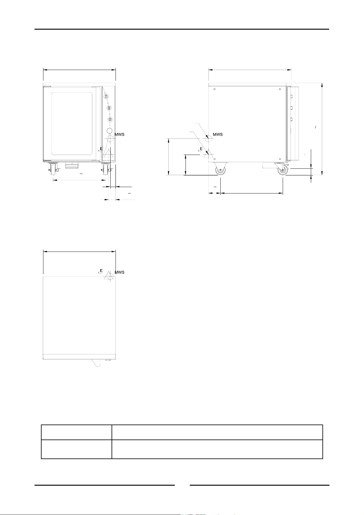
Specifications
BAP89 Proofer / Holding Cabinet - BACO32E Oven
28"
20
32"
WATER ENTRY
"
1
2
"
49
1
43
ELECTRICAL ENTRY
2
WATER ENTRY
14"
8"
ELECTRICAL ENTRY
5
"
4
8
24"
E
1
1
"
4
2"
5
"
2
8
"
3
8
25
4"
"
8
7
64
"
1
2
35
"
8
5
2
Front
28"
Plan
Side
4
Page 9

Installation
Installation Requirements
It is most important that this appliance cabinet is installed correctly and that the
operation is correct before use.
Installation shall comply with local electrical, health and safety requirements.
Before Connection to Power Supply
• Remove all packing.
• Check equipment and parts for damage. Report any damage immediately to the carrier and
distributor.
• Remove protective plastic coating from the side panels.
• Report any deficiencies to the distributer who supplied the appliance.
• Check that the available power supply is correct to that shown on the rating plate located on the
right-hand side panel.
Model Electrical Rating
BAP89110-1
110-120 Volts A.C, 60 Hz, 1P+N+E, 1.5 kW, 12.5 A.
Location
• To ensure correct ventilation for the and controls the following minimum installation clearances are
to be adhered to:
Rear 0” / 0 mm.
Left-hand side 0” / 0 mm.
Right-hand side 1” / 25 mm.
• Position the proofing and holding cabinet in its working position.
• Use a spirit level to ensure it is level from side to side and front to back.
• The unit should be positioned such that the operating panel and oven shelves are easily
reachable for loading and unloading.
Electrical Connection
WARNING:
THIS APPLIANCE MUST BE EARTHED / GROUNDED.
• BAP89 Proofing / Holding Cabinets are supplied with cords fitted. Ensure that the unit is fitted with
the correct cord and plug.
• To access the electrical connection terminal block, grounding lug and strain relief, remove the right
hand side service access panel.
Water Connection
• A cold water supply should be fitted to the water inlet which is located near the rear of the right
hand side of the unit.
• A connection elbow and sealing washer is supplied with this unit for direct connection of a ½” ID
hose, and is recommended for easy installation and service.
• Connect water supply - Max inlet pressure 80psi / 550kPa.
• Turn on water supply to check for leaks.
5
Page 10

Installation
Rack Width
• The BAP89 Proofer / Holding Cabinet has been designed to accept either 18” or 16” wide trays or
steam pans.
• The Proofer / Holding Cabinet comes factory set for 18” trays, a rack spacer kit (Part No. 025685) is
required to change to 16” trays or steam pans.
Stacking with Convection Oven
• The BAP89 Proofer / Holding Cabinet is supplied for stand alone use.
• Optionally, the BAP89 Proofer / Holding Cabinet can be combined beneath a Belshaw Adamatic
TrueBake BACO32E Convection Oven as a complete unit. For this a stacking kit is required.
• For installation of the stacking kit, refer to the instruction sheet provided with the stacking kit.
6
Page 11

Operation Guide
Operation
Description
of
Controls
Function
O Unit is ‘Off’.
PROOF Unit is in proofing mode (indicator illuminates).
HOLD Unit is in holding mode (indicator illuminates).
Thermostat
Temperature range 32 - 185°F.
65 - 105°F Proofing range.
150 - 185°F Holding range.
Indicator illuminates when the elements are cycling ON to
maintain set temperature.
(Controls the cabinet air temperature).
Humidity Control
P
R
O
O
F
D
L
O
H
1 to 5 Setting for butter based pastries (croissants,
Danish pastries etc).
5 to 8 Settings for yeast based breads and doughs.
Indicator illuminates when elements are cycling ‘On’ to
maintain set temperature.
(Controls the cabinet humidity in PROOF Mode only).
Thermometer
Indicates cabinet temperature.
Dual Fahrenheit and Centigrade scale.
Condensation Channel
Below the door there is a condensation channel and
removable water collection drawer for the purpose of
collecting door condensation run-off.
7
Page 12

Operation
Operating in ‘PROOF’ Mode
Ensure that power is supplied to the unit and the water trough is filled.
It is recommended that the proofer operates empty before loading with product.
- Warm days up to 10 minutes - Cool days up to 30 minutes.
1. Ensure water tank is filled with water
Check the water tank is full and that the heating element is covered with water.
2. Set function to PROOF
Indicator light will illuminate when the switch is in the “PROOF” position.
3. Set thermostat to desired proving temperature
Indicator light will illuminate when the elements are cycling on to maintain set temperature.
75 - 85°F Butter based pastries.
95 - 105°F Yeast based breads and dough's.
4. Set humidity to desired level
Indicator light will illuminate whenever elements are cycling on to maintain set humidity.
As a guide;
Set humidity to between 6 to 7 marks on control panel as a general rule. Increase or
decrease as necessary for specific product types.
Humidity is required only to avoid product dry skinning on surface. Do not set humidity
such that product becomes sticky and wet on surface. A silky to touch surface on the
product is a general recommendation for correct humidity levels.
Avoid excess humidity levels as this will also create excess condensation in the cabinet
interior.
NOTE: Butter based product require much less humidity than breads.
Bake-Off
This proofer has been designed for use together with a refrigerator and oven to take frozen uncooked
yeast or butter based products to finished cooked products.
1. Prepare product.
Arrange frozen products onto baking trays.
2. Thaw.
Refrigerate at 39°F overnight. Do not leave standing at room temperature or product may dry out.
3. Prove.
Place thawed products directly from the refrigerator into the pre-heated proofer. Proof for 30-60
minutes dependant on product and food proving recommendations.
4. Bake.
Place the proofed product directly from the proofer into the pre-heated oven. We recommend the
Belshaw Adamatic BACO32E Turbofan Oven.
8
Page 13

Operation
Problem Solving
Product Collapses
When using frozen dough which collapses or shrinks in the oven after proofing, this is caused by too
much proofing. Reduce the proofing time for the next batch.
Dry Product
The dough piece in the proofer should never be dry to the touch. A moist, firm and silky membrane
should cover the dough piece during proving.
Wet Product
The dough piece in the proofer should not be wet to touch whilst proofing and should not adhere to
fingers. Water should not condense on the trays. If it does there is either too much moisture or too
little heat in the proofer.
If there are any problems with your dough the most likely causes are as follows:
• Too much heat and too little moisture.
• Not enough heat and too much moisture.
• Proofing time too long or too short.
• Incorrect oven temperature.
• Incorrect maturity adjustment in the formulation of the dough for the flour.
• Incorrect thawing procedure, or handling of the dough after thawing.
Hints
Heat
It is better to operate the proofer at a lower temperature with adequate moisture rather than at a
hotter temperature with too little moisture.
Yeast
Yeast activity starts very slowly at about 41°F and increase in speed or gas production as the
temperature rises. When a temperature of approximately 140°F is reached, the yeast is killed and
baking of the aerated product starts. Thus different rates of proofing occur as the temperature
changes.
Flour
The amount of proofing required is determined by the quality of the GLUTEN in the flour. Gluten is
a rubber like product and can perish if stretched too far by too much proofing. Collapsing of the
product or shrinkage will occur.
Proof
You must recognise the proof of the product by the appearance of the dough rather than the size.
9
Page 14

Operation
Operating in ‘HOLD’ Mode
Ensure that power is supplied to the unit and the water trough is filled.
It is recommended that the cabinet operates empty before loading with product.
- Warm days up to 10 minutes - Cool days up to 30 minutes.
1. Set function to HOLD.
Indicator light will illuminate when the switch is in the ‘HOLD’ position.
2. Set thermostat to desired holding temperature.
Indicator light will illuminate when the elements are cycling on to maintain set temperature.
3. Humidity.
The humidity is not used in ‘HOLD’ Mode. The setting on this dial will have no effect as the
wet element is disabled.
4. Thermometer.
The thermometer gives an accurate reading of the cabinet temperature to ensure that the
product being held is at the correct temperature.
10
Page 15

Cleaning
Cleaning Guidelines
C
AUTION
Always turn off the electrical supply at the mains supply before cleaning.
This appliance is not water proof.
Do not
use water jet spray to clean interior or exterior of this appliance.
Cabinet
Clean with a good quality stainless steel cleaning compound. Harsh abrasive cleaners may damage
the surface.
Side Racks
To remove, take hold of the centre rung and lift upwards to disengage the rack key-holes from the
hanger studs. To replace, hold horizontally, engage keyholes onto studs and push down.
Door
Wash with warm water and detergent solution using a soft sponge in straight lines up and down the
door. Rinse with clean, warm water and dry off.
:
Clean door seal with warm water and detergent solution using a soft sponge when required.
Water Tank
To remove lift RH side rack and pivot at rear, remove tank by lifting off its hanger studs. Clean with
warm soapy water. Rinse thoroughly and refit.
Water Tank Element
When the element becomes limed/scaled remove the water trough and clean. Replace water trough
and half fill with white vinegar or acetic acid, then fill to the normal level with water. Switch the unit
on, turn the humidity to ‘8’ and operate for approximately 30 minutes. Remove trough and clean the
element with a damp cloth when cooled. Rinse out the trough and refit to unit.
This procedure is recommended to be carried out once a week. Frequency of cleaning the element
may be increased or decreased depending on the lime depositing on the element.
Water Trough Access
Water Trough Removal
2
1
Open right hand rack support.
1) Lift rack upwards to disengage keyholes.
2) Hinge on rear supports to open.
2
1
Lift out water trough.
1) Lift trough upwards to disengage keyholes.
11
Page 16

Fault Finding
This section provides an easy reference guide to the more common problems that may occur during the
operation of your equipment. The fault finding guide in this section is intended to help you correct, or at
least accurately diagnose problems with your equipment.
Although this section covers the most common problems reported, you may encounter a problem not
covered in this section. In such instances, please contact your local authorised service agent who will
make every effort to help you identify and resolve the problem. Please note that the service agent will
require the following information:-
• The Model Trade Name and the Serial Number of the Appliance. (Both can be found on
the Technical Data Plate located on the appliance).
Fault Possible Cause Remedy
The proofer / holding cabinet
does not operate / start.
No humidity. Unit is in ‘HOLD’ mode.
Slow recovery. Overloading of cabinet.
Door does not close. Tray in way of door. Correctly position tray in rack.
The mains isolating switch on the
wall, circuit breaker or fuses are
‘Off’ at the power board.
The power switch on the cabinet
is ‘Off’.
No water in trough.
Door opened unnecessarily.
Turn ‘On’.
Rotate switch. Indicator will
illuminate.
Switch unit to ‘PROOF’ mode.
(Humidity is only generated in
‘PROOF’ mode).
Fill with water.
Reduce batch size.
Do not open unnecessarily.
12
Page 17

Wiring Schematic
BAP89 Proofer / Holding Cabinet - Circuit Schematic
8
7
5
1 3
2 4 6
LIGHT
LIGHT
2x 15W 110V
2x 25W 240V
N/C
FLOAT
SWITCH
RELAY
WATER
SOLENOID
FAN
POWER
PILOT
LIGHT
HUMIDITY
ELEMENT
800W 240V
2
1
THERMOSTAT
HUMIDITY
PILOT
LIGHT
600W 110V
800W 240V
600W 110V
DRY
2
1
1
P1
2
F
O
D
L
O
O
R
H
P2
OFF
4
4
P4
3
3
P3P2
2
2
1
1
P1
FUNCTION SWITCH OPERATION
PROOF
HOLD
4
3
21
P2P1 P3 P4
P2P1 P3 P4
FUNCTION SWITCH
3
P
P3
4
R
W
P
P4
THERMOSTAT
ELEMENT
800W 240V
600W 110V
HOLD
ELEMENT
13
GROUND
Page 18

Wiring Schematic
BAP89 Proofer / Holding Cabinet - Wiring Diagram
800W 240V
800W 240V
600W 110V
2626
FAN MOTOR
WET
ELEMENT
32
WIRE MARKING
"VIVID" PEN
27
11
28
25 25
27
28
29
24
600W 110V
HOLD
ELEMENT
7
31
29
30
23
16
800W 240V
600W 110V
DRY
ELEMENT
EARTH
POWER SUPPLY CORD
6
35
E
L N
POWER
INDICATOR
2
SWITCH
FUNCTION
32
LIGHT
33
34
LIGHT
25W 240V
LIGHTS
15W 110V
22
14
TEMP
INDICATOR
15
HUMIDITY
INDICATOR
5
7
3
2
1
P2
P1
18
8
4
3
P4
P3
4
6
2
DRY
3
23
1
(0-85°C)
THERMOSTAT
10
2
WET
(30-85°C)
1
THERMOSTAT
13
12
1
4
1
MAINS
BLOCK
TERMINAL
17
11
WIRE MAKING
"VIVID" PEN
EARTH
9
18
9
21
20
7
8
5
6
3
4
1
2
RELAY
19
19
14
WATER
22
SOLENOID
FLOAT SWITCH
Page 19

Replacement Parts List
Replacement Parts List
IMPORTANT:
Only genuine authorized replacement parts should be used for the servicing and
repair of this appliance. The instructions supplied with the parts should be followed
when replacing components.
For further information and servicing instructions, contact your nearest authorized
service branch (contact details are as shown on the reverse of the front cover of this
manual).
When ordering replacement parts, please quote the part number and the description as listed below. If the
part required is not listed below, request the part by description and quote model number and serial
number which is shown on the rating plate.
Main Assembly Parts List - BAP89
Pos Part No. Description
1 - - - - - - DOOR ASSEMBLY (Refer Page 18).
2 025598 DOOR SEAL.
3 020082 HINGE TOP (ASSEMBLED WITH BUSH).
4 020083 HINGE BOTTOM (ASSEMBLED WITH BUSH).
017905 HINGE BUSH.
5 025609 RACK SPACER (OPTIONAL EXTRA).
025685 RACK SPACER KIT.
6 025608 LH RACK WA.
7 025604 RH RACK WA.
8 - - - - - - CONTROL PANEL ASSEMBLY (Refer Page 17).
9 025566 HANGER STUD.
10 022758 CATCH PLATE.
11 025732 CONDENSATE DRAWER.
12 025601 RACK STANDOFF.
13 013890 CASTOR - SWIVEL.
14 015759 DRY ELEMENT - 600W (110V).
15 013885 CASTOR - RIGID.
16 021342 LAMP HOLDER.
014219 BULB 15W (115V).
17 025575 SIDE PANEL.
18 025567 WATER TANK.
19 012271 CLAMP BOTTOM.
012275 CLAMP TOP.
20 015230 WET ELEMENT - 600W (110V).
21 019238 SNAP BUSH 19mm.
22 025573 TERMINAL BLOCK PANEL.
23 013586 TERMINAL BLOCK.
24 002441 INSULATOR.
25 002138 CABLE CLAMP.
26 025580 FAN MOTOR BRACKET.
27 013999 MOTOR - (110V).
28 022097 SENSOR BRACKET.
29 022252 FLOAT SWITCH SLEEVE.
30 022253 ADAPTOR & LOCKNUT.
31 022998 REDUCING SOCKET 3/8” x 1/8”.
32 025574 WATER TUBE.
33 021617 WATER SOLENOID - (110V).
34 022250 FLOAT SWITCH.
35 021535 RELAY - (110V).
36 020869 CONNECTOR 3/8”F x 1/4” COMPRESSION.
37 024702 WATER SOLENOID BRACKET.
38 021619 REAR SERVICE PANEL TOP.
15
Page 20

Replacement Parts List
Main Assembly - BAP89
16
Page 21

Control Panel Assembly - BAP89
Replacement Parts List
Pos Part No. Description
1 025582 CONTROL PANEL.
2 233234 OVERLAY BELSHAW ADAMATIC BAP89°F.
3 022789 SELECTOR SWITCH.
4 022787 THERMOSTAT 0-85°C (Dry).
5 024527 THERMOSTAT 30-85°C (Wet).
6 023857 PILOT LIGHT (110V).
7 020823 KNOB.
8 021472 KNOB (Humidity).
9 022788 THERMOMETER.
10 024694 CONTROL PANEL HOOK.
17
Page 22

Replacement Parts List
Door Assembly - BAP89
1
2
3
4
5
6
7
8
9
Pos Part No. Description
1 025519 DOOR HANDLE.
2 020082 HINGE TOP ASSEMBLY.
3 025588 DOOR OUTER.
4 090202 DOOR OUTER SEAL - 2.02m.
5 025599 DOOR GLASS.
6 025593 DOOR INNER FRAME.
7 020083 HINGE BOTTOM ASSEMBLY.
8 018947 MAGNETIC CATCH (INNER).
9 025600 MAGNET MOUNTING PLATE.
10 090203 DOOR INNER FRAME SEAL - 2.00m.
11 025598 DOOR SEAL.
10
11
18
 Loading...