

Page 1

iXPanelTA150
Service&MaintenanceManual
MAEN014A,2010-12
English
Page 2

Service&MaintenancemanualforiXPanelTA150
Foreword
This manual contains detailedinformation about iX Panel TA150, including
descriptions of variousactions that can be carried out inorder to maintain or
update the operator panelhardware and software.
The manual contains descriptionsof basic maintenance and replacement of
common parts in iX Panel TA150.
The manual assumes thatthe most recent versions of the system program
(firmware) and iXDeveloper are used.
The followingother manuals are available for iXPanel TA150:
iX PanelTA150installation manual (MAEN011x) for in formation regarding
installation.
iX Developer reference manual (MAEN831x) for a descriptionof the
configuration tool.
iX Developer user’s guide (MAEN832x) for function-based descriptions.
Foreword
Order no: MAEN014A
Copyright © 2010-12 Beijer Electronics AB. All rights reserved.
The information inthis document is subject tochangewithoutnoticeandisprovidedasavailableatthe
time of printing. Beijer Electronics AB reserves the rightto change any information without updating th is
publication. Beijer Electronics AB assumes no responsibility for any errors that mayappear inthis document.
Read the entireinstallation manual prior to installing and usingthis equipment. Only qualified personnel
may install, operate or repair this equipment. Beijer ElectronicsAB is not responsible for modified, altered
or renovated equipment. Because the equipment hasa widerangeofapplications,usersmustacquirethe
appropriate know l edge to use the equipment properly in their specific applications. Persons responsible
for the application and the equipment must themselves ensure that each application is in compliance with
all relevant requirements, standards and legislationinrespecttoconfigurationandsafety. Onlypartsand
accessories manufactured according to specifications set by Beijer ElectronicsAB may be used.
BEIJER ELECTRONICSAB SHALL NOT BE LIABLE TO ANYONE
FOR ANY DIRECT, INDIRECT, SPECIAL, INCIDENTAL OR
CONSEQUENTIAL DAMAGESRESULTING FROMTHE
INSTALLATION, USE OR REPAIR OF THIS EQUIPMENT, WHETHER
ARISING IN TORT, CONTRACT, OR OTHERWISE. BUYER'S SOLE
REMEDYSHALL BE THE REPAIR, REPLACEMENT, OR REFUND
OF PURCHASE PRICE, ANDTHE CHOICE OF THE APPLICABLE
REMEDYSHALLBEATTHESOLEDISCRETIONOFBEIJER
ELECTRONICSAB .
BeijerElectronics, MAEN014A
Page 3

Contents
Contents
1 Safety Precautions ....................................................... 5
1.1 General ...........................................................
1.2 During Installation ..............................................
1.3 During Use .......................................................
1.4 Service and Maintenance ........................................
1.5 Dismantling and Scrapping .....................................
2 Introduction ............................................................. 7
2.1 iX PanelTA150 ..................................................
2.2 Maintenance .....................................................
2.3 Service andRepairs ..............................................
2.4 Dismantling and Scrapping .....................................
2.5 Contact andSupport ............................................
3 Installation ............................................................... 10
3.1 Space Requirements .............................................
3.2 InstallationProcess ..............................................
3.2.1 Connections tothe Controller ........................ ..........
3.2.2 Other Connections andPeripherals ......................... ....
4 TechnicalData ........................................................... 14
5 ChemicalResistance .................................................... 15
5.1 Metal Casing .....................................................
5.2 Touch Screen and Overlay .. .....................................
5.2.1 AutotexF157/207 ....... ........................................
5.2.2 TouchScreenSurface ....... .....................................
5.2.3 AutoflexEB ........ ..............................................
6 Hardware Tests .......................................................... 18
7 Hardware Replacement ................................................. 19
7.1 Mode Switches ...................................................
7.2 Cables .............................................................
7.3 Replacing the Rear Cover ........................................
7.4 Replacing the Display/Disp
7.4.1 Self TestoftheDisplay ... ........................................
7.4.2 CalibratingtheTouch Screen ....................................
layCable ..........................
7.5 ReplacingtheCompleteFront ..................................
7.6 Replacing the Backlight .. .......................................
7.7 Available SpareParts for iX Panel TA150 .......................
8 Service Menu ............................................................ 27
8.1 Service Menu in an Empty Panel ...............................
8.2 Service Menu in a Panel with Project ...........................
8.3 Service Menu Options ...........................................
8.3.1 IPSettings ..................... ..................................
8.3.2 Date/Time ........................... ............................
8.3.3 EraseProject ................ .....................................
8.3.4 TouchCalibrate ...... ...........................................
9 Hardware Self Test ...................................................... 29
9.1 Self Test Items ....................................................
10
10
13
13
15
16
16
17
17
19
20
21
22
23
23
24
25
26
27
27
27
27
28
28
28
30
5
5
6
6
6
7
8
8
8
9
BeijerElectronics, MAEN014A
Page 4

Contents
10 AdditionalInstallation Tips . ........................................... 31
10.1 Grounding the OperatorPanel .................................
10.2 Ethernet Connection in the Panel ..............................
10.3 To Achieve Better EMC Protection .............................
10.4 Ambient Temperature ...........................................
10.5 Safety .............................................................
10.6 GalvanicIsolation ................................................
10.7 Cable and Bus Termination RS485 .............................
31
32
33
34
35
36
37
11 Fault Tracing ............................................................. 38
12 Software .................................................................. 40
12.1 General Information aboutSoftware ...........................
12.1.1 Software Products ....... ........................................
12.2 Update Software .................................................
12.2.1 iXDeveloper ................................................. ....
12.2.2 Remote AccessViewer ............ ...............................
12.2.3 System Program ..................... ............................
40
40
41
41
41
41
13 Environmental Aspects ................................................. 43
13.1 General Environmental Aspects ................................
13.2 Environmental Impactofthe OperatorPanels .................
13.2.1 Mechanical Components .................. ......................
13.2.2 Electronics ............ ...........................................
13.3 Recycling .........................................................
13.4 Environmental Impact Report ..................................
43
43
43
43
44
44
BeijerElectronics, MAEN014A
Page 5

Safety Precautions
1SafetyPrecautions
Both the installer andthe owner and/or operator of the operatorpanel must read
and understand thisinstallation manual.
1.1 General
• Read the safety precautionscarefully.
• Check the delivery for transportation damage. If damage is found, notif y the
supplier as soon as possible.
• Do not use the operator panel in an environment with high explosive hazards.
• The supplier is not responsible for modified, altered or reconstructed
equipment.
• Use only parts and accessories manufactured accordingto specifications of
the supplier.
• Read the installationand operating instructions carefully before installing,
using or repairingthe operator panel.
• Neverallowfluids,metalfilingsorwiringdebristoenteranyopeningsinthe
operator panel. This may cause fire or electrical shock.
• Only qualified personnel may operate the operator panel.
• Storing theoperator panel wherethe temperature is lower/higher than
recommended in this manualcan cause the LCD display liquid to
congeal/become isotopic.
• The LCD display liquid contains a powerful irritant. In caseof skin contact,
wash immediately with plenty of water. In case of eyecontact, hold the eye
open,flushwithplentyofwaterandgetmedicalattention.
• Thefiguresinthismanualservesanillustrativepurpose. Becauseofthemany
variables associated with anyparticular installation, the suppliercannot
assume responsibility for actual use based onthe figures.
• The supplier neither guarantees thatthe operator panel is suitable for your
particular application, nor assumes responsibility for your productdesign,
installation or operation.
1.2 DuringInstallation
• The operator panelis designed for stationary installation on a plane surface,
where thefollowing conditions arefulfilled:
– no high explosive risks
– no strong magnetic fields
– no direct sunlight
– no large, sudden temperature changes
• Install the product according to the accompanying installation instructions.
• Ground theproduct according to the accompanying installation instructions.
• Only qualified personnel may install the operator panel.
• Separate the high voltage,signal and supply cables.
• Make surethat the voltage and polarity of thepower source is correct before
connecting the product to the power outlet.
• Peripheralequipment must be appropriate for theapplication and location.
BeijerElectronics, MAEN014A
5
Page 6

Safety Precautions
1.3 DuringUse
• Keep the operator panel clean.
• Emergency stop and othersafety functions may not be controlled from the
operator panel.
• Do not usetoo much force or sharp objects when touching the keys,touch
screenetc.
1.4 ServiceandMaintenance
• Only qualified personnel should carry out repairs.
• The agreed warranty applies.
• Before carrying out any cleaningor maintenance operations, disconnect the
equipment from theelectrical supply.
• Clean the display andsurrounding front cover with a soft cloth andmild
detergent.
• Replacing the battery incorrectly may resultin explosion. Only use batteries
recommended by the supplier.
1.5 DismantlingandScrapping
• The operator panelor parts thereof shall be recycledacc
regulations.
• The followingcomponents contain substances t
to health andthe environment: lithium batter
display.
hat might be hazardous
y, electrolytic capacitor and
ording to local
BeijerElectronics, MAEN014A
6
Page 7
Introduction
2Introduction
This manual describes howto maintain the iX PanelTA150.
The functions availablein iX Developer depend onwhich operator panel model is
used.
2.1 iXPanelTA150
The followingdrawings are available foriX Panel TA150:
• Outline drawing
• Panelcut-out
BeijerElectronics, MAEN014A
7
Page 8

Introduction
2.2 Maintenance
Carefully read the instr uctions before beginning maintenance on theoperator
panel.
• Only qualified personnel should carry out maintenance.
• The agreed warranty and license agreements apply.
• Any damage tothe operator panel caused by personnel invalidates the
warranty.
• Before carrying out any cleaningor maintenance operations, disconnect the
operator panel fromthe power supply.
• Clean the display andsurrounding front cover with a soft cloth andmild
detergent. Recommended cleaning fluids for the display are water and IPA
(Isopropyl Alcohol orHexane).
• Replacing the battery incorrectly may resultin explosion. Only use batteries
recommended by the supplier.
• A 6-month warrantyon all service parts is provided.
Maintenance personnel are permitted to carry out the following actions:
• Replacing the Rear Cover
• Replacing the Display/Display Cable
• Replacing the Complete Front
• Replacing the Backlight
2.3 ServiceandRepairs
• Only accredited companies are permitted to perform service and repairs.
• Ifanon-accreditedcompanyconductsanykindofserviceorrepair,theagreed
warranty will be i nvalidated.
• If training is required,contact the supplier.
• All maintenance should be performed in a 15-30 °C temperature range.
• Any damage tothe operator panel caused by personnel invalidates the
warranty.
• Contracts with customers supersede the information in thisdocument.
2.4 DismantlingandScrapping
• The operator panel, or parts thereof, should berecycled according to local
regulations.
• The followingcomponents contain substances that mightbe hazardous to
health and theenvironment: lithium battery, electrolytic capacitor, display.
BeijerElectronics, MAEN014A
8
Page 9

Introduction
2.5 ContactandSupport
If you wantto report a fault or have aquestio n about the operator panels, please
contact your localsupplier or fill out the form onthe web site.
1.
Enter the web site www.beijerelectronics.com and selectSupport.
2.
Select Contact inthe menu. Make sure to provideinformation about type
number, serial number, environmentand an installation description.
The form will besent to the manufacturer’s help desk and they will answer your
question or registeryour improvement/fault.
To ensure quick resolution, provideas many details as possible in your report.
Include the date and time when the problem occurred, a description of what you
were trying to do, the detailed steps you took that led up to the problem, and
details about any error messagesreceived.
BeijerElectronics, MAEN014A
9
Page 10

3Installation
3.1 SpaceRequirements
• Installation plate thickness: 1.5 - 9.0mm (0.06 - 0.35 inch)
• Space requirementswhen installing the operator panel:
100 mm
(4.0 inch)
304 mm
(11.97 inch)
50 mm
(2.0 inch)
100 mm
(4.0 inch)
398 mm
(15.67 inch)
50 mm
(2.0 inch)
60 mm
(2.36 inch)
Installation
100 mm
(4.0 inch)
Caution:
Theopeningsontheenclosureareforairconve
ction. Donot covertheseopenings.
3.2 InstallationProcess
1.
Unpack and check the delivery. If
Note:
Placethe operatorpanelonastablesurfaceduring installation.
Droppingitorlettingitfallmaycause damage.
damage is found, notify the supplier.
Panel cut out 355.5 x 278.5 mm
(14.0 x 10.96 inch)
x 14
BeijerElectronics, MAEN014A
10
Page 11
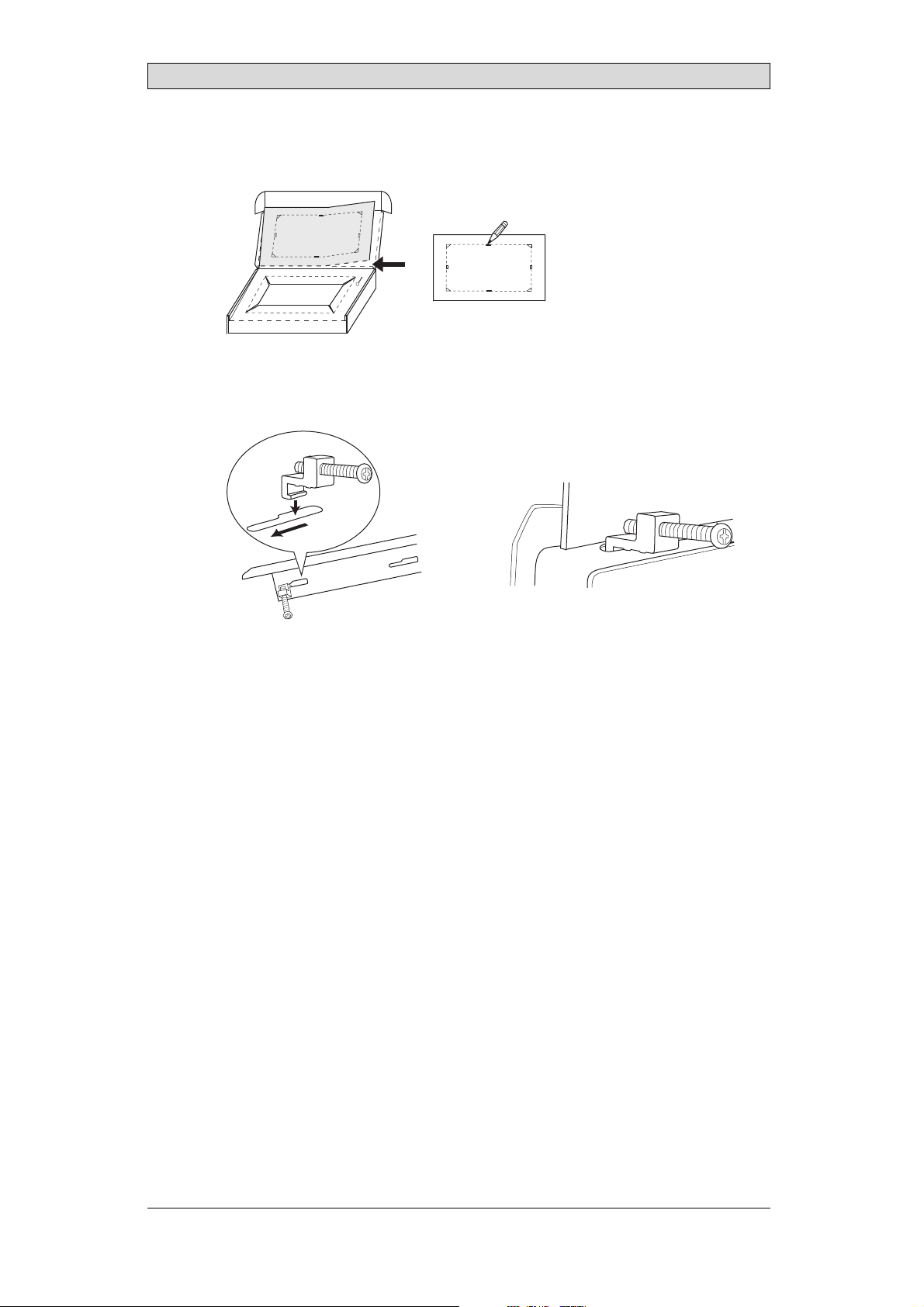
2.
Place thepanel cut out where theoperator panel is to besituated, draw along
the outer sides of theholes and cut according to themarkings.
3.
Secure the operator panel in position, using all the fastening holes and the
provided brackets and screws:
x 14
Installation
0.5 - 1.0 Nm
BeijerElectronics, MAEN014A
11
Page 12
Installation
4.
Connect the cables in the specified order, accordingto the drawing and steps
below.
Caution:
• Ensurethattheoperatorpanelandthecontrollersystemhavethesame electrical
grounding(referencevoltagelevel),otherwiseerrors incommunicationmay
occur.
• Theoperatorpanelmustbebroughttoambient temperaturebeforeitisstarted
up. Ifcondensation forms,ensurethattheoperatorpanelisdrybeforeconnecting
itto thepoweroutlet.
• Ensurethatthevoltageandpolarity ofthepowersourceiscorrect.
• Useonly shieldedcommunicationcables.
• Separatehighvoltagecablesfromsignalandsupplycables.
Power
CF CARD
B
1
Controller
RS422/RS485
RS232
24V DC
24V DC
C
D
A
Ethernet
– Connect cable A.
– Connect cable B, using an M5 screw and a grounding conductor (as short
as possible) with a cross-section of minimum 2.5 mm
– Connect cable C.
– Connect cable D.
5.
Carefully removethe laminated film over the operator panel display, to avoid
2
.
static electricity that could damage the panel.
BeijerElectronics, MAEN014A
12
Page 13

Installation
3.2.1 ConnectionstotheController
Forinformation about the cables to be usedwhen connecting the operator panel to
the controller,please refer to the help file forthe driver in question.
3.2.2 OtherConnectionsandPeripherals
Cables, peripheral equipment and accessories must besuitable for the application
and its environment. Forfurther details or recommendations, pleaserefer to the
supplier.
BeijerElectronics, MAEN014A
13
Page 14
Technical Data
4TechnicalData
Parameter iX Panel TA150
Frontpanel,WxHxD 398x304x6mm
Mountingdepth 60mm (160mmincludingclearance)
Frontpanel seal IP66
Rear panel seal IP 20
Keyboard
material/Front
panel
Reverseside
material
Weight 3.7 kg
Serialport
RS422/RS485
SerialportRS232C 9-pinD-subcontact,malewithstandardlocking screws4-40
Ethernet 2x shieldedRJ45
USB HosttypeA(USB 2.0),m ax outputcurrent500m A
Memoryslots 1x SDcard
Realtimeclock ±30PPM +errorbecauseofambienttemperature. Total
Power consumption
atrated voltage
Display TFT-LCD.1024x768 pixels,64Kcolors.
Activeareaof
display,WxH
Fuse InternalDCfuse,3.15AT, 5x20mm
Powersupply +24VDC (20-30VDC).Powersupplyconnector.
Ambient
temperature
Storagetemperature -20°to+70°C
Relativehumidity 5- 85%non-condensed
Approvalsand
certifications
Touch screen: Polyesteronglass,1millionfinger touch
operations. Overlay: AutotexF157orF207*.
Powder-coatedaluminum
25-pinD-sub contact,chassis-mountedfemalewith
standardlo cking screws4-40UNC
UNC
maximumerror: 77seconds/monthat25°C.
Temperature coefficient: -0.034±0.006ppm/°C
Rechargeablebattery.
Normal: 1.2A
Maximum: 1.7A
CCFLbacklight lifetimeat theambienttemperatureof
+25°C:>35,000h.
304.1x 228.1mm
CE:The powersupplymustconformwiththerequirements
accordingtoIEC60950andIEC 61558-2-4.
ULand cUL:Thepowersupplymustconformwith the
requirementsforclassIIpowersupplies.
Verticalinstallation: 0°to+50°C
Horizontalinstallation: 0°to +40°C
Informationisavailableon thewebsite
www.beijerelectronics.com
2
*SeesectionChemicalResistanceformore information.
BeijerElectronics, MAEN014A
14
Page 15

Chemical Resistance
5 ChemicalResistance
5.1 MetalCasing
The frame and casing material is powder-coated aluminum. This powder paint
withstands exposure to the following chemicals without visible change:
Aceticacid 10% Phosphoricacid4%
Citricacid10% Phosphoricacid10%
Diesel Seawater
Distilledw ater Sodiumchloride2%
Edibleoil Sodiumchloride20%
Fueloil Sulphuricacid 20%
Hydrogenperoxide3% Tap water
The powderpaint shows limited resistance to the f
ollowing chemicals atroom
temperature:
Butanol Nitricacid3%
Hydrochloricacid5% Nitricacid10%
Isopropylalcohol Phosphoricacid43%
Na-hypochlorite10% Turpentine
Note:
Ifexposureto anyofthe abovechemicalsisdemanded,itisrecommendedtofirsttest
thechemical onan“invisible”spotofthemetalcasing.
Thepowderpaintshowslittleornoresistancetothefollowingchemicalsatroom
temperature:
Aceticacid, conc. Methyl-ethylketone Toluene
Acetone Nitricacid 30% Trichlorethylene
Ammonia5% Phenol Xylene
Ammonia,conc. Sodiumhydroxide5% 97octanunleadedpetrol
Ethylacetate Sodiumhydroxide30% 98octanle ad edpetrol
BeijerElectronics, MAEN014A
15
Page 16

Chemical Resistance
5.2 TouchScreenandOverlay
5.2.1 AutotexF157/207
Autotex F157 or F207 covers the overlay surrounding the touch screen.
SolventResistance
Autotex F157/F207 withstands exposure of more than 24hours duration under
DIN42115Part2tothefollowingchemicalswithoutvisiblechange:
Acetonitrile DieselDowney/Lenor
Ajax/ Vimin solution EthanolPotassiumferricyanide
Alkalicarbonatesolution1Glycerine Potassiumhydroxide
Ammonia(<40%)
Aceticacid (<50%) Gumption
Arielpowderinsolution
1
Bleach
Castoroil Methanol Trichloroaceticacid
Causticsoda(<40%)
Cuttingoil Paraffinoil Windex
Cyclohexanol Persilpowderinsolution1Wisk
Diacetonealcohol Petroleumspirit
1
Extremelyfaintglossingofthe texturewasnoted.
1
1
Glycol PureTurpentine
1
1
Hydrochloricacid(<36%) Sulfuricacid(<10%)
Linseedoil Toma to ketchup
Nitricacid (<10%) WhiteSpirit
1
Phosphoricacid(<30%)
(<30%)
SBP60/95
(<50%)
1
-
1
1
Autotex withstands DIN 42 115Part 2 exposure of up to 1 hour duration to glacial
acetic acid withoutvisible change.
Autotex is no
t resistant tohigh pressure steam at over 100°C or the following
chemicals:
Concentratedmineralacids Benzylalcohol
Concentratedcaustic solution Methylenechloride
OutdoorUse
In common withall polyester based films AutotexF157/F207 is not suitable for
use in conditions of long term exposure to directsunlight.
BeijerElectronics, MAEN014A
16
Page 17

Chemical Resistance
5.2.2 TouchScreenSurface
Thetouchscreensurfaceonthepanelwithstandsexposuretothefollowing
solvents without visible change:
Solvents Time
Acetone 10minutes
Isopropanol 10minutes
Toluene 5 hours
5.2.3 AutoflexEB
It isrecommended to use the Autoflex EB touchdisplay protection film, that can
be ordered from Beijer Electronics.
SolventResistance
Autoflex EB withstands exposure to the same chemicals asAutotex F157 or F207
according to section AutotexF157/207.
OutdoorUse
In common withall polyester based films Autotex EB is not suitable for use in
conditions of long term exposure to direct sunlight.
BeijerElectronics, MAEN014A
17
Page 18

Hardware Tests
6 HardwareTests
Before the operator panels are approved for market introduction, theyare tested
by independent authorities. The iX Panelsare examined by several authorities
before being approvedfor market introduction. A ll operator panels are designed
to fulfill standards such as CE. The quality policy and environmental policy place
demands on all suppliersand subcontractors.
The manufacturer performs extensive hardware testing before an operator panel
is approved. Some tests are performed byexternal testing companies, such as
the SwedishNational Testing and Research Institute. All operator p anels are
submitted to testingbefore leaving the manufacturer.
BeijerElectronics, MAEN014A
18
Page 19
Hardware Replacement
7 HardwareReplacement
This section containsinstructions on how to replace operatorpanel hardware.
Only components included in the latest bill of material and spareparts list are
allowed. See Available Spare Parts for iX Panel TA150.
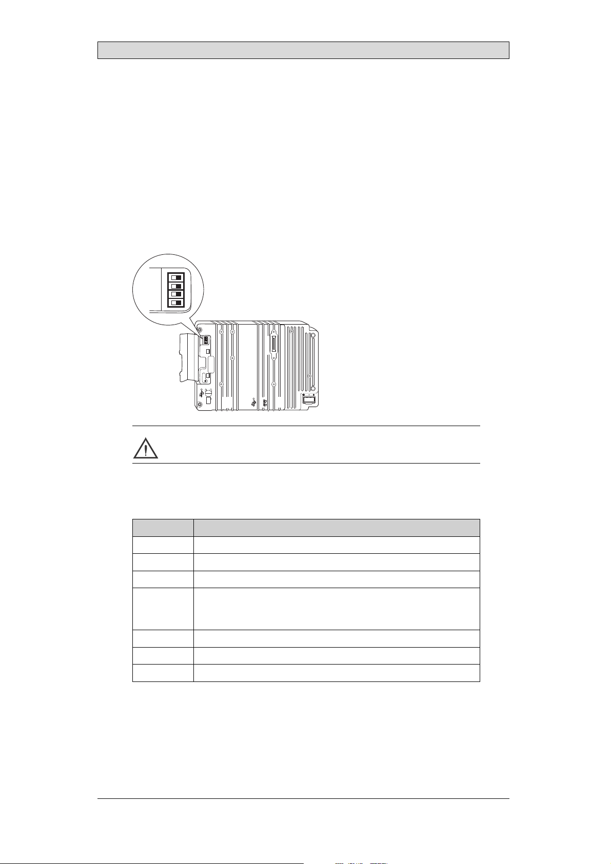
7.1 ModeSwitches
The iX Panel TA150 has four modeswitches (DIP switches) located on the rear
side of the operator panel.
1 2 3 4
MODE
ON DIP
10/100
EXPANSION
RS232
COM 2
24V DC
1
1 2 3 4
MODE
ON DIP
CF CARD
BUSY
COM 1
RS422
RS485
Warning:
Themodes belowaretobeusedwithcaution.
Themodeswitcheshavethefollowingfunctions: 1=ON,0=OFF
Each letter in “MODE” has a corresponding mode switch.
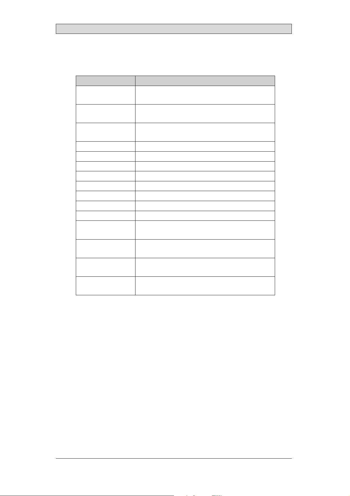
MODE Description
0000 “Runmode” -bootsCE,normaloperation.
0010 Notused.
0100 Notused.
1000 ServiceMenumode,theservicemenuforthesystemprogramis
shown. Allowsthe usertosetIPconfiguration,erasethe project,
calibratethe touchscreenetc. SeesectionServiceMenufordetails.
1100 Notused(runmode).
1110 Selftest.
xxx1 Not used.
To change mode switches, follow the steps below:
1.
Disconnect power from the operator panel.
2.
Set the mode switches using a ballpoint pen.
3.
BeijerElectronics, MAEN014A
nnect power to the operator panel.
Reco
19
Page 20

Hardware Replacement
7.2 Cables
Mostoftheoperatorpanelsusethesametypeofflexcableconnectors.
connector flanges
Flex cable connector
To release the flex cables fromthe connector, gently push the two flangeson the
cable connector towards theflex cable.
Note:
Theconnectorsmustbeunlockedonbothsidesbeforeremovingthecable,otherwise
theflexcablemaybedamaged.
BeijerElectronics, MAEN014A
20
Page 21

Hardware Replacement
7.3 ReplacingtheRearCover
The followingis needed:
• Anewrearcover,seeAvailable Spare Parts for iX Panel TA150
• AtorxT10screwdriver
Note:
MakesuretouseadequateESDprotection.
Follow the stepsbelow to replacethe rear cover:
1.
Poweroff the operator panel.
2.
Remove the rear cover of the operator panel by loosening the 4torx screws.
4 x torx screws
3.
Re-assemble withthe new rear coverin reverse order.
BeijerElectronics, MAEN014A
21
Page 22

Hardware Replacement
7.4 ReplacingtheDisplay/Display Cable
The followingis needed:
• A new display/display cable, see Available Spare Parts for iX Panel TA150
• AtorxT10screwdriver
Note:
MakesuretouseadequateESDprotection.
Followthe steps belowto replace the display/displaycable:
1.
Poweroff the operator panel.
2.
Followthe instructions under Replacing the Rear Cover to remove the rear
cover.
3.
Disconnect the two flex cables the flex cable and the LED cable fromthe
power cardand remove the two plastic nuts that hold thepower card in place.
LED cable
plastic nut
display cable
plastic nut
4.
Lift the powercard and gently remove thebacklight cables and the display
cablefromtherearsideofthepowercard.
backlight cable
display cable
backlight cable
BeijerElectronics, MAEN014A
22
Page 23

Hardware Replacement
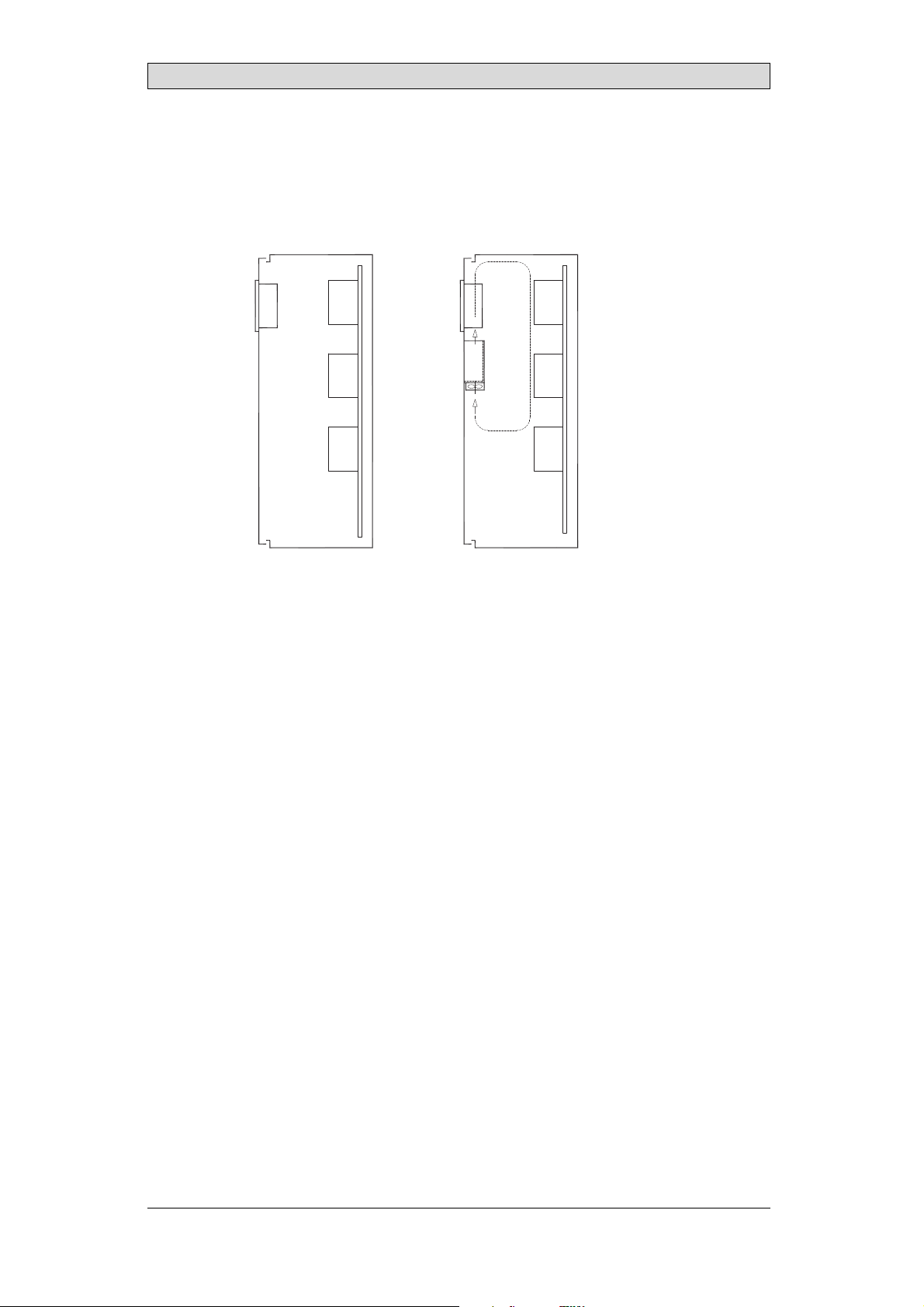
5.
Remove themounting plate (12 torx screws). Gently lift the mounting plate
with the display and power card.
12 x torx screws
6.
Flip the mounting plate and unscrew the 4 torx screws, located onfront or
side.
4 x torx screws
7.
Re-assemble the panel in reverse order.
7.4.1 SelfTestoftheDisplay
To perform a self test of the display, followthe steps below:
1.
Start theoperator panel in a self test mode(see table in the Mode Switches section).
2.
Go to the displaytest, by running or skipping the preceding tests. Verify that
the display works.
3.
If the screendoes not work, try fault tracing, see the Fault Tracing section.
7.4.2 CalibratingtheTouchScreen
Followthe steps below to calibrate the touch screen:
1.
Set the MODE switches to thecorrect positions in order to enterthe Service
Menu mode (see table in the Mode Switches section).
2.
Switchon the power and follow the instructions.
3.
Poweroff the operating pa
4.
Reset all MODE switches to theOFF position.
nel.
BeijerElectronics, MAEN014A
23
Page 24

Hardware Replacement
7.5 ReplacingtheCompleteFront
The followingis needed:
• Anewfront,seeAvailable Spare Parts for iX Panel TA150
• AtorxT10screwdriver
Note:
MakesuretouseadequateESDprotection.
Followthe steps belowto replace the completefront of the iX Panel TA150:
1.
Poweroff the operator panel.
2.
Followthe steps 1-3 and 5 in the Replacingthe Display/Display Cable instructions, but in step3, only disconnect the flex cable and the LED cable(do not
remove the power card).
3.
Attach the new front.
4.
Re-assemble the unit.
BeijerElectronics, MAEN014A
24
Page 25

Hardware Replacement
7.6 ReplacingtheBacklight
Note:
Alllamps inthedisplaymustbereplacedat thesametime.
The followingis needed:
• Two new backlights, see Available Spare Parts for iX Panel TA150
• AtorxT10screwdriver
• A screwdriverPhillips size 0 or 00
Note:
MakesuretouseadequateESDprotection.
Followthe steps below to replace the battery of the iXPanel TA150:
1.
First,follow the steps1–5 in section Replacing the Rear Cover.
2.
Remove thetwo cross-headed screws to the backlight, using the Phillips size
00 screwdriver. This way,backlights can be removed withoutremoving the
plate.
2 x cross headed screw
3.
Remove the backlights.
4.
Insert the new backlights. Be careful not to pull thecables of the new
backlights when inserting them, since pulling the cableswill damage the
backlights.
5.
Re-assemble the complete operator panel.
2 x backlight
BeijerElectronics, MAEN014A
25
Page 26
Hardware Replacement
7.7 AvailableSparePartsforiXPanel TA150
Ordernumber Description
601009278 COMPLETEFRONT
Includingfrontcover,touchoverlay, gasketsandlabels
601009041 DISPLAY
Includingframeandcable
601009049 BACKLIGHT
Includestwopieces,topandbottom
601009042 DISPLAYCABLE
321099040 POWERCONNECTOR
601009011 REARCOVER
601009003 CFCOVER
601009001 MOUNTINGBRACKETS
601009048 TOUCHPROTECTIONSHEET
601009296 FRONTLABEL
601009146 COMPLETEBOX
601009008 TESTPLUGETHERNET
EthernetRJ45testconnector
601009006 TESTPLUGRS232
RS232test connector
601009007 TESTPLUGRS422/485
RS422/485testconnector
601009069 TESTPLUGUSBH
USBHosttestconnector
BeijerElectronics, MAEN014A
26
Page 27

Service Menu
8ServiceMenu
The service menu for theoperator panel can be accessed beforea project is
downloaded, or by setting th e mode switches in mode 1000. The location of the
mode switches is des cribed in the Mode Switches section.
8.1 ServiceMenuinanEmptyPanel
When no project isloaded in the panel memory,the panel will boot, displaying the
Welcome screen. Press anywhere on the panel display to enter the service menu.
8.2 ServiceMenuinaPanelwith Project
When a project is loaded in the panel memory, the panel willautomatically start to
execute theproject. To display the service menu atboot-up:
1.
Disconnect the powersupply from the panel.
2.
Set the mode switches in mode 1000 (Service Menu mode).
3.
Connect the powersupply.
When the panelboots up it will suggest to go into the Touch Calibrate mode.
This ensures that it willbe possible to recover froma bad calibration.
4.
Pressanywhere on the panel display to interrupt the timer and to enter the
service menu.
5.
Make desiredsettings in the service menu.
6.
Disconnect the powersupply from the panel.
7.
Set themode switches in mode0000 (Run mode).
8.
Reconnect thepower supply.
8.3 ServiceMenuOptions
The followingoptions are available in the ServiceMenu:
8.3.1 IPSettings
The panel hastwo built-in Ethernet ports, according to the drawing below. For
each port, selectto obtain an IP address automatically via DHCP, or specify an
IP address for the first Ethernet port.
Port 1
The port that is currently connected is recognized by a *.
BeijerElectronics, MAEN014A
Port 2
27
Page 28

Service Menu
8.3.2 Date/Time
Use the Date/Time Settingsdialog to set the time zone, date and timefor the
panel.
8.3.3 EraseProject
The erase functionwill detect if the projectis located in the panelmemory or ona
memory card. Pressing Erase Project will completely removethe project and all its
components from the panelmemory/the memory card.
8.3.4 TouchCalibrate
SelectTo uc h Ca li br at e if the touch screen needs tobe calibrated. Followthe
instructions on the screento perform a calibration.
BeijerElectronics, MAEN014A
28
Page 29

Hardware Self Test
9 HardwareSelfTest
The self testprogram can be used to test aspectsof operator panel functionality
and thecommunication ports. To run the testyou will need:
• Test plugs, including two Ethernet test plugs; see Te st pl u g d ra wi ng .
• 24 V DC, min. 3 A.
• SD card
Followthe steps below to run the self test program on the operator panel:
1.
Poweroff the operator panel.
2.
Go to the self test. Set the mode switches tothe self test positions, s ee the table
in the Mode Switches section.
3.
Power on the operator paneland follow the instructions at the bottom of the
display.
4.
When using thetest plugs, make sure the +5V DC LED on the RS422 test
plug and theLED of the RS232 test plug areon.
5.
When the selftest is finished, power off theoperator panel and set all mode
switches tothe OFF position.
If an error occurs during the self test, try to fault trace. See Fault Traci
ng.
BeijerElectronics, MAEN014A
29
Page 30
Hardware Self Test
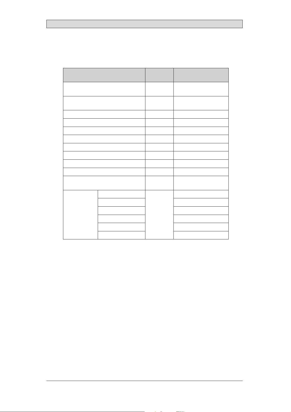
9.1 SelfTestItems
The following tests, of whichsome may be dismissed, are performed:
Maybe
Test item
RS422(short-circuit) No 25pinD-sub plug(male);
RS232(short-circuit) No 9pinD-subplug(female);
EEPROM No CoreTemperature No BoardTemperature No Touch Yes Buzzer Yes Power LED Yes Backlight Yes Display Yes SDCard Yes SDcardmustbe
BurnIn
(loopwith
6repeating
tests)
CoreTemperature BoardTemperature Ethernet1 RJ 45 plug
Ethernet2 RJ 45 plug
RS422 25pinDSUB plug(male)
RS232
dismissed Plug
maynot beconnected
mayno t bepluggedin
connected
Yes
9pinDSUBplug(female)
BeijerElectronics, MAEN014A
30
Page 31

Additional InstallationTips
10 AdditionalInstallationTips
When experiencing communication problems in for example noisy environments
or when operating closeto temperature limits, the following recommendations
are to benoticed.
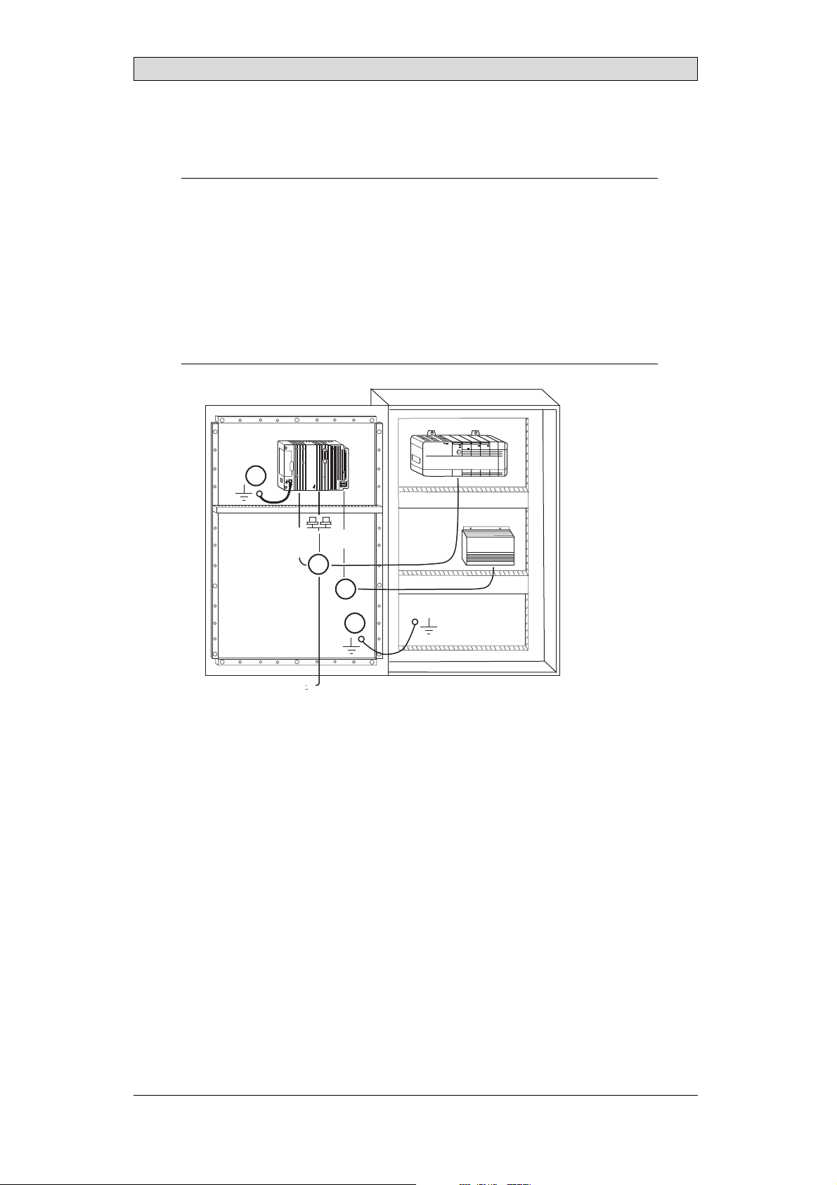
10.1 GroundingtheOperatorPanel
Door
Operator panel
1
Ferrite core
3
2
5
6
4
Mounting plate in the cabinet
Power supply
24 V DC
5350
The operator panel’s mounting clamps do not provide a securegrounding
connection between the panel and the device cabinet, see1 in drawing above.
1.
Connect a 2.5 mm
and the panel chassis, see2 in drawi
2.
Connect a 6 or 4mm
2
wire betweenthe ope
rator panel’s quick-connect plinth
ng above.
2
wire or groundingbraid between the panel’s chassis and
the closest grounding pointon the door,see 3 in drawing above.
3.
Connect a strong but short grounding braid between the door and thedevice
cabinet,see 4 in drawing above.
4.
Twist the cables onto the24 V DC feed, see 5in drawing above.
2 turns aroundthe ferrite core provide 4 times the suppression of 1 turn.
3 turns aroundthe ferrite core provide 9 times the suppression of 1 turn.
A ferrite core suppresses disturbances to the 24 Vfeed, see 6 in drawing above.
Note:
Thegroundingwiresshouldbeshortandtheconductor shouldhavealargearea.
Along, thingroundingwirehasaveryhighimpedance(resistance)athighfrequencies
andwill notguidedisturbancestotheground.
Multi-wireconductors arebetterthansinglewireconductorswiththesamearea.
Abraidedconductorwirewith thesameareaisevenbetter. Thebestisashort,thick
groundingbraid.
BeijerElectronics, MAEN014A
31
Page 32

Additional InstallationTips
10.2 EthernetConnectioninthePanel
Industrial Ethernet
RJ45
RJ45
RJ45
RJ45
Operator panel
RJ45
1
2
Operator panel
RJ45
Operator panel
RJ45
Operator panel
RJ45
5351
Shielded
0.1 uF
250 V
3
4
1-1
2-2
3-3
8-8
Short and
unshielded
5
In some industrialunits for Ethernet, the RJ45 contact’s shield is connected to the
chassis via a capacitor, see 1 in drawing above.
The operator panel’s Ethernet shield is directly
connected to the chassis, see 2 in
drawing above.
1.
Check whether the other Ethernetunit has its shield directly grounded or
grounded via a capacitor.
Note:
Inmanycases,connecting theshieldedEthernetcablingtothechassisatbothendsis
inappropriate. Humo r groundingloopscanoccur. Unshieldedcablingmayevenresult
infewercommunicationerrors.
A good solution may beto use a shielded Ethernet cable, but toconnect the shield
at one end only.
One option is to break the shield, see 3 in drawing above.
A more elegantmethod is to expand the shielded Ethernet cabling witha piece of
unshielded Ethernetcable, see 4 in drawing above.
You can ground the shield via an external 0.1uF/250 V plastic capacitor,see 5 in
drawing above. This will connect theHF transients to the ground.
BeijerElectronics, MAEN014A
32
Page 33

Additional InstallationTips
10.3 ToAchieveBetterEMCProtection
• Initially,use the original cabling from BeijerElectronics primarily.
• Use shielded cables for RS232 communication.
• Use twisted pair andshielded cabling for RS422 and RS485.
• Use the cabling intended for the bus ty pe; Ethernet, Profibus, CC-Link,
CAN, Device Netetc.
• Install and connect according to applicable specifications for the relevant bus
standard.
• Use shielded cabling forEthernet, preferably with foil+ braided shield.
• D-sub covers should be shielded, andthe shield should be connected to the
cover 360° where the cable comes in.
• Connect the shield at both ends.
Shielded cable
0.1 uF/250 V
Ground plane 1 Ground plane 2
Ground plate Ground plate
Not same potential
in another building
5352
With longer distances, there is a risk that the ground potential may be d ifferent.
In that case,the shield should only be connected at one e nd. A good alternative
is to connect the other end of the shield to the ground via a 0.1 uF/250V plastic
capacitor. Both endsare then connected to the ground in terms of HF, but only
connected to the ground at one end in terms ofLF, thus avoiding the 50 Hz
grounding loops.
Metal cabinet Metal cabinet
Terminal or connector Terminal or connector
Cable clamp
in steel
Short distance
EMC cable gland Plastic cable gland
Shielded cable Shielded cable
1.
Usean EMC cable gland or regular plastic cable gland,remove the outer jacket
5353
and connect theshield to the installation plate with a 360 ° metal cable clamp.
2.
Place the 24V DC and communications cabling in one cable trunk/cable duct
and 230/380 V AC in another. If the cables need to be crossed, cross them at
90 ° only. Avoidcombining the cabling for stronger 24 V DCoutputs with
the communication cabling.
Ferritecores that are snappedonto the shielded cabling mayremove minor
disturbances. Large ferrite pieces that aresnapped onto unshielded cablingand
where the wiresgo 2-4 times around the coresare approximately 5-25 times more
efficient.
BeijerElectronics, MAEN014A
33
Page 34
Additional InstallationTips
10.4 AmbientTemperature
The maximum ambient temperature for the operator panel is provided in the
specifications. The ambient temperature refers to the temperature in the device
cabinet which cools the panel’s electronics.
Top
50 °C inside
Operator
panel
30 °C outside
Middle
45 °C inside
Bottom
40 °C inside
Power
Power
Power
Axial fan
120 x 120 mm
Airflow
5354
Inmostcases,theambienttemperaturefortheoperatorpanelissignificantly
higher than thedevice cabinet’s ambient temperature.
If the cabinetis tall and there area number of hea
temperature at thetop of the cabinet will be con
theoretical temperature increasethat would
sensitivetoheat. Thelifespanofanelectro
° increase in temperature. A 15-20 ° tempera
t-generating devices,the
siderably higher than th e
be expected. All electronics are
lytic capacitor iscut in half with an 8-10
ture increase results in a quarter of the
lifespan etc.
Rittal has a good program for estimating the anticipated averagetemperature in
the cabinet as well as a large program for controlling thetemperature in the device
cabinet.
An enamel-coated steelcabinet has
a radiant heat value of 5.5 W/m
2
and degrees
C.
Installing a faninside the cabinet will even out thetemperature, while moving air
provides considerably better cooling than still air. A suitable fan is a120 x 120 mm
axial fan, availablein 24 V DC, 115 and 230 V AC.
Installthefansothatitsit
operator panel. If the fan i
ambient temperaturewill
s in thecooler area and will blow cold air against the
s mounted at the top and sucks air upwards, the fan’s
be higher = shorter lifespan.
Agoodfanwithaball-bearingmountinghasanexpectedlifespanofatleast
40,000 hours (nota guaranteed lifespan) at 40 °C.This corresponds to at least 4
years of continuoususe. If a thermostatis installed, the fan only needs tocome
on when needed.
Large graphic termi
lighting is off. Th
nals draw only one fifth of the current when the background
e loss effect dropsfrom e.g. 25 Wto only 5 W.
The operator panel’s loss effect = supply voltagex current. Virtuallyno power goes
to external users andno loss effects due to inputs.
BeijerElectronics, MAEN014A
34
Page 35
10.5 Safety
Most of the operator panels are fed with 24 V DC.
Power supply
1
2
3
230 V AC to 24 V DC
Power supply
230 V AC to 24 V DC
Power supply
230 V AC to 24 V DC
230 V AC
+24 V
0 V
4
+24 V
0 V
4
Distance?
+24 V
0 V
4
Operator panel
Operator panel
Operator panel
Small controller with expansion unit
COM1
COM100
Ch0
Ch1
Ch100
Ch101
5355
Additional InstallationTips
Ifyouuseapowersupplythatmeetssafetystandardsandonlyfeedstheoperator
panel, there is no problem. See 1 in drawing above.
However,ifyouhavea24Vunitthatalsofeedsotherunits,thereisreasontobe
cautious, see 2 indrawing above. The operator panel doesnot have insulation that
meets safety requirementsin the event of a potential short circuit between 230V
AC and 24V DC. It is assumed that the 24V feed is secure, for example, SELV
according to EN 60950 (protection against electric shock) and UL 950.
Example:
Hereis anexamplethatexplainswhyasecure24V DCfeedcanberuinedbymixing 24
Vrelaycontactswith230VACrelaycontactsinasmallercontroller. Checkthatthe
“clearancesand creepagedistancesbetween24VDCand230VACfulfillEN60950orUL
950”. Ifnot, inputaseparate24V unitintotheoperatorpanel.
If there is asubstant
AC, it is OK to use the
ial distance between therelay contacts for 24 V DC and230 V
same 24 V devices for all feeds. See 3 in drawing above.
Connect 0 V onthe 24 V feed to the ground, see4 in drawing above. This offers
three advantages:
• Safety is increa
connection or s
• Tr a n si e n t s o n
• No risk that th
is not unusua
sed. The24Vfeedwillnotbeliveintheeventofafaulty
hortcircuitbetween0V(24V)and230Vphase.
the 24 V feed are connected to the ground.
e 24 V feedis at a high level in relationship to theground. This
l since there is high static electricity.
BeijerElectronics, MAEN014A
35
Page 36

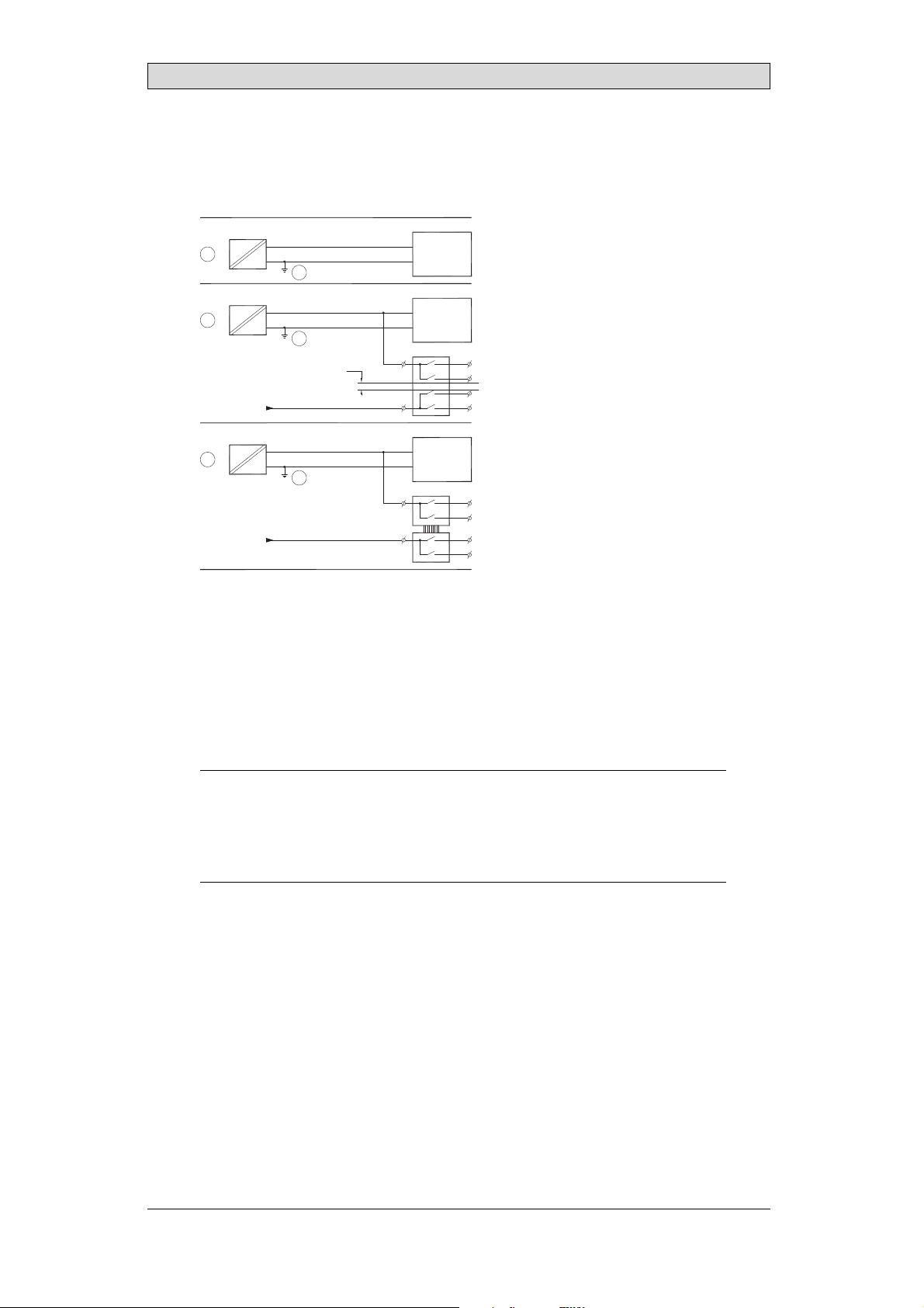
10.6 GalvanicIsolation
r
Additional InstallationTips
+24 V DC
DC/DC
galvanic isolation
Filter
0 V
1.5 m
Internal electronic
VCC
0 V (GND)
RS232RS422/485
USB
USB
DC/AC
Ethernet
CFL
5356
The operator panelhas galvanic isolation against the 24 V DCfeed but no galvanic
isolation between the communication ports forRS232, RS422/485 and USB.
Only the Ethernetconnection has galvanic isolation.
Operator panel Modular controller Printe
RS422 RS232 USB
**
* *
Not same ground potential
* = Internal 0 V (GND) connection
When a PC is connected to the panel, the panel’s internal 0 V (G
*
Power CPU COM COM2
***
*
PCPC
5357
ND) will be
connected to the protective groundvia the PC.
A number of USBdevices can have the shield connected together with the
protective ground. Here, the panel’s 0 V (GND) is connected to the protective
ground when, for example, a USB memory stick, keyboard or similar device is
plugged in.
If a number of units are connected that have a 0 V a
these are connected to various grounding poin
problems. Grounding currents go through com
of the controller, and internally inth
e operator panel, and can cause errors.
nd a ground c onnection, and
ts, there isa substantial risk of
munication cables, the rearplate
Use e xternal units to improvecommunication and achieve galvanic isolation.
Westermo has good industry-standard insulators that arealso insulated from the
24 V DC feed.
Note:
Itis veryimportanttomakesurethatthe 24Vfeedinthe externalinsulationunitisnot
connectedtooneofthe communicationoutlets. Ifitdoesnothave100% insulation
againstthe24Vfeed,disturbancesandgroundingcurrentsfromthe0Vonthe24V
sidewill disruptcommunication.
Usingthis typeofunitsolvesoneproblembutcreatesalargerproblem! Asubstandard
installationmayworknow,b ut problemsmayarisewhenotherdevicesareconnected.
BeijerElectronics, MAEN014A
36
Page 37

Additional InstallationTips
10.7 CableandBusTe rminationRS485
• Use sh ielded and twisted p air cable. The pair capacitance may notexceed 52.5
2
pF/m and areaat least 0.25 mm
(AWG 24), if you want touse the maximum
transfer distance and maximumtransfer speed.
• 0 V, the reference voltagefor communication should be included in
the cabling. With two-way communication use two pairs; one pair for
communication and one pairfor 0 V.
• The shield must be grounded at one end. The other end is usuallyground ed,
but with longer distances or whenthere is a difference in theground potential,
theshieldshouldbeconnectedtothegroundvia0.1uF/250Vplastic
capacitor to prevent ground currentin the braided shield. A number of
manufacturers recommendthat the shield be grounded at each node. Various
manufacturers have differentsystems for bus termination. The RS485
standard does notdescribe how the “FailSafe” function would becarried out,
justthatthesystemshouldbeabletohandletheerror.
Depending on therecipients’ design, the bus wires may be on the samelevel or
require pull-upor pull-down to ensure that nofaulty signals are detected when the
bus is in resting mode (all transmitters are disconnected).
Inside operator panel
+5 V
0 V
1 23
1 K
120 ohm 120 ohm
1 K
+5 V
(120 ohm)
14
1 K
2
15
6
19
1 K
7
8
0 V
0 V
4
55
17
50
Operator
panel
RS422
1 2 3 4 5 6 7 8
CAB8CAB8 Bus
2
15
3
16
17
4
14
+5 V
VCC
8
0 V
7
0 V
VCC
1 K
120 ohm
1 K
RS485
1
2
3
4
5
6
Shield
7
8
Bus termination
0 V
0 V
5358
Some (older) operator panel s had pull-up and pull-down resistance except for
the actual bus termination at120 ohm, similar to Westermoand Profibus. See 1
in drawing above.
Newer panelshave another type of recipient, so-called built-in “Fail Safe”,where
simple bus termination resistance is sufficient. See 2 in drawing above.
If other nodes onthe RS485 network require pull-up andpull-down and the
operator panel is at one end of the loop, one of thefollowing procedures can be
carried out:
• Connect two 1k/0.25 W resistorsin the 25-pole D-sub contact. See 3 in
drawing above. Set jumperpins 6-19.
• Use CAB8. It offers the option of bus termination with pull-up/-down. It
isalsoeasytoconnectthebuscableviathescrewterminalblock. See4in
drawing above.
BeijerElectronics, MAEN014A
37
Page 38

Fault T racing
11 FaultTracing
This section includesdifferent fault scenarios and steps to follow to trace the fault.
TheiXPanelTA150isnotworkingproperly,andthe
powerLEDis off
1.
Isthepowervoltagecorrect?
2.
Does the powersupply deliver enough current?
3.
Check the fuse.
4.
Check the power card.
5.
Is thepower card correctly mounted?
TheiXPanelTA150isnotcommunicatingwiththe
controller
1.
Check the communication cable between the units.
2.
Check that the operator panelhas a controller driver downloaded.
3.
Checkthatthecorrectcontrollerdriverisused.
4.
Check the communicationports on the CPU board.
TheiXPanelTA150isworkingbutthebacklightisoff
1.
Check the backlight dimming.
2.
Check that the backlight is connected to the power card.
3.
Replace the backlight according to the Replacing th
4.
Check the DC/AC onthe power card.
eBacklightsection.
TheiXPanelTA150isnotworking,thebacklightisoff
butthepowerLEDison
1.
Check the backlight dimming.
2.
Check the CPUboard for burned components.
3.
Download new firmwareto the operato
rpanel.
TheiXPanelTA150doesnotincludethelatestimage
1.
Check the versions i ncluded with the operator panel.
2.
Make sure to save a copy of the project to the PC.
3.
Download anupdated image wi
in the System Programsectio
th the Image Loaderand follow the directions
n.
BeijerElectronics, MAEN014A
38
Page 39

Thetouchscreenismalfunctioningorisnot
respondingatall
1.
Re-calibrate the touch screenaccording to the Calibrating the Touch Screen sec-
tion.
2.
Check that the flex cableis correctly fitted.
3.
Replace the display of the operator panel according to the
Replacing the Display/Display Cable section.
4.
Check the touch interface on the powercard.
Linesindisplayhavewrongcolororthedisplay
pictureisshifted
1.
Check if the display has a wide vertical or horizontal area across the
display. It should be at least2-3 cm wide with a grey or black c o lor. See
Replacing the Display/Display Cable for instructions on howto correct this.
2.
Make sure the display cable is correctlyfitted.
3.
Make surethe display cable is not folded ordamaged in any way. Replace the
display cableaccording to the Replacingthe Display/Display Cable section.
Fault T racing
BeijerElectronics, MAEN014A
39
Page 40

Software
12 Software
This chapter describes how to maintain and update the software inthe iX Panels.
The chapter includes a general description of the operator panel softwareand
instructions about how to upgrade thesoftware and load projects and system
programs.
12.1 GeneralInformationabout Software
The software requiredto run and maintain the operator panels is found on the
software USB stick. It isalso available through your local distributor.
The software istested by the manufacturer’s own testing department before
market introduction is approved. The test procedure is closely integrated with the
development process. The test group works in close concert with the developers
andisISEBCertifiedforSoftwareTesting.
12.1.1 SoftwareProducts
The followingsoftware products are used:
• iX Developer
iX Developer is u sed for creating application projects for iX Panels and their
accessories.
• Remote AccessViewer
Remote AccessViewer is a program for remote ac
It ispossible to access, reflect and control t
client programRemote Access Viewer (freew
server (Remote Accessfunction) in th
• System Program
The iX Panel TA150 is delivered with an image (operating system) pre-stored in
the operator panel memory.
eiXPanels.
cess and control of the iX Panels.
he iX Panels from a PC using the VNC
are) together with thebuilt-in VNC
BeijerElectronics, MAEN014A
40
Page 41

12.2 UpdateSoftware
When an update is available, an e-mail is sent to the distributors. The software is
also available onthe manufacturer’s web site.
Theupdateshouldbeinstalledbyqualifiedpersonnel.
12.2.1 iXDeveloper
iX Developer is not a freeware product.
A demo versioncan be downloaded from www.beijerelectronics.com.
To update iX Developer, an accredited iX Panels dealer must be contacted.
12.2.2 RemoteAccessViewer
This software isincluded on the iX Developer USB stick.
To update the Remote Access Viewer, go towww.beijerelectronics.com and select
Support/Downloads inthemenu. BrowsethesoftwarefoldertolocateRemote
Access Viewer. Runthe .exe file and followthe instructions.
Software
12.2.3 SystemProgram
An upgrade of thecomplete software package is sometimes needed to take
advantage of new functionality.
The upgrade is done by running the Image Loader execu
IML_TA70–150_bxxx.exe. The Image Loader applica
through the upgrade.
Two upgrade options are available:
• Upgradingthe System Program Usinga USB Memory S
• Upgradingthe System Program via Ethernet
Whentheupgradeisfinished,theoperatorpanelwillreceivethedefaultIPaddress
192.168.1.1. Followthe instructions on the screen after startup to change t he IP
address.
Note:
TheImageLoadersoftware isonlyintendedforcustomersandpartnersthathave an
operatorpanel. Nootherdistributionisallowed.
Note:
Whenupgradinganoperatorpanel,itisimportanttoensurethatpoweris not
interruptedduring theupgrade.
table file,
tion will help andguide you
tick
BeijerElectronics, MAEN014A
41
Page 42

Requirements
Upgrading of the operator panel system program requiresthe following:
• APC
• An Ethernet connection between the PC andthe operator panel or an empty
USB memory stick.
• The Image Loader executable file from the web site
UpgradingtheSystemProgramUsingaUSBMemory
Stick
When upgrading the system program using a memory stick, you can select to
delete or to keepthe project in the operator panel.
Followthe steps below:
1.
Connect an empty USB memory stick to your PC.
2.
Double-click on the e xecutable Image Loader file.
3.
Select the driveof the desired USB stick and click Create.
The files arecopied to the USB stick.
4.
Connect the USB memory stick to the operator panel.
5.
Cyclethepowertoinitiatetheupgrade.
Software
UpgradingtheSystemProgramviaEthernet
When upgrading the system programvia Ethernet, the project in the operator
panel is retained.
Followthe steps below:
1.
Make sure that your PC and the operator panel are connectedvia Ethernet.
2.
Double-click on the e xecutable Image Loader file.
3.
Enter the IP addressof the operator panel.
4.
Click Update, and followthe instructions.
The files aretransferred to the operator panel. The panel will reboot
automatically when the transfer is finished.
BeijerElectronics, MAEN014A
42
Page 43

Environmental Aspects
13 EnvironmentalAspects
This chapter includes information about theenviron mental impact of iX Panels.
More information can be found on the manufacturer’s web site.
13.1 GeneralEnvironmentalAspects
The manufacturer’s activities meet internal requirementsas well as those of the
SS-EN ISO 9001:2000and SS-EN ISO 14001:2004 internationalstandards.
13.2 EnvironmentalImpactofthe OperatorPanels
13.2.1 MechanicalComponents
The aluminum and stainlesssteel used in the mechanical components are judged
to be non-environmentally hazardous. The expanded rubber packing for thefront
and the expanded polyethylenepacking for the display contain an adhesive that is
not classified as environmentally hazardous.
Screws may haveundergone the followingsurface treatments: Bright
nickel-plating or bright zinc-plating. Themembranekeyboardismadeof
polyester with silver wiring. On some models the keyboardcontains LEDs.
Display framesand CF covers are made of halogen-free plastic, PC/ABS.
13.2.2 Electronics
CircuitBoard
Note:
AlloperatorpanelsareRoHScompliant.
The electronics are complex and almost all elements of the periodic table are
represented.
Display
There is a separate circuit board for the display. The liquid crystals in thedisplay
are cyclohexanecompounds. The fluorescenttube contains mercury and lead
solder.
Batteries
The operator
classified a
(1997:645
panel contains a buttoncell lithium battery. The battery is not
s environmentally hazardousby the Swedish Battery Ordinance
).
BeijerElectronics, MAEN014A
43
Page 44

Environmental Aspects
13.3 Recycling
The operator panelsconsist largely of aluminum. It is a greatadvantage in terms of
both resources and the environment if it can be recycled. Make sure that operator
panels taken out ofservice are sent tofacilities for electronic scrap.
The manufacturer’s electronic waste is recycled by Stena Technoworld AB.
Aluminum front/rearcasings and othercovers can be removed and recycled.
Plastic display frames and CF covers must be recycledas hard plastic. The circuit
board containsmany valuable metals and should thereforebe recycled.
Remove the lithium battery. Electrolytic capacitors and displays are currently not
classified as hazardouswaste, but may be harmful tohealth and the environment.
The electrolytic capacitors should behandled as per Handbook 2001:7 (NFS)
and displays asper NFS 2001:8.
Thefluorescenttubemustbehandledashazardouswaste.
The packagingis made from wood fiberand shouldberecycled. Thelargeprinted
label on the front,however, must first be removed as it ismade of PVC vinyl. The
label and theplastic bag for the brackets are recycled as softplastic.
The manufacturer is a member of the REPAregister. The protective film on the
front is recycledas soft plastic. When the operator panel is no longer useful it
can be returnedto the manufacturer for environmentally responsible recycling.
Contact the company for further information.
13.4 EnvironmentalImpactReport
An operator panel impacts the environment through itsfunction, i.e., controlling
industrial equipment. The energy and the scrapped parts that canbe saved with
efficient management meanthat the operator panel contributes to reduced
environmental impact.
Listed below are examples of how you canreduce environmental impact during
operator panel use.
• Switch the system off when not in use.
• Use green electricity.
• Use energy-saving options, e.g.,turn off the backlight to both save energyand
reduce wearon the fluorescent tube.
• If possible, reduce the backlight brightness to reduce energy consumption
and increase fl uorescent tube service life.
Supplythe operator panel with 2
effect increases. Ensure that
recycled in an environmentall
4 V DC. Ifthe input voltage is lower, the loss
the operator panel, battery, and packaging are
y responsible manner.
BeijerElectronics, MAEN014A
44
Page 45

Headoffice
BeijerElectronicsAB
Box4 26
20124Malmö,Sweden
www.beijerelectronics.com/+4640358600
 Loading...