

Page 1

iXT7AM
InstallationManual
MAEN118A,2013-06
English
Page 2

Foreword
InstallationmanualforiXT7AM
Foreword
All are developed to satisfy the demands of human-machine communication.
Built-in functions such as displaying and controlling tex t, dynamic indication,
time channels, alarm and recipe handlingare included.
The operator panel works primarily in an object-oriented way, making it easy to
understand and use. Configuration is carried out on a PC using the iX Developer
configuration tool. The project can then be transferred and stored in the operator
panel itself.
Various types of automation equipment such PLCs, servos or drives can b e
connected to the . In this manual, the term “the controller” refers to the connected
equipment.
This manual explains how to install the operator panel. Please refer to the
iX Developer reference manual for further information.
Order no: MAEN118A
Copyright © 2013-06 Beijer Electronics AB. Allrights reserved.
The information in thisdocumentissubject to changewithoutnoticeandisprovidedasavailableatthe
time of printing. Beijer ElectronicsAB,includingallitsgroupcompanies,reservesthe right to change any
information without updating this publication. Beijer Electronics AB, including all its group companies,
assumesnoresponsibilityforanyerrorsthatmayappearinthisdocument. Readtheentireinstallation
manual prior to installing and using this equipment. Only qualified personnel may install, operate or repair
this equipment. Beijer Electronics AB, including all its group companies, are not responsible for modified,
altered or renovated equ ipment. Because the equipment has a wide range of applications, users must acquire
the appropriate knowledge to use the equipment properly in their specific applications. Persons responsible
for the application and the equipment must themselves ensure that each application is in compliance with
all relevant requirements,standardsand legislationinrespecttoconfigurationandsafety. Onlypartsand
accessoriesmanufacturedaccording to specifications set by Beijer ElectronicsAB,includingall i ts group
companies, maybeused.
BEIJER ELECTRONICS AB, INCLUDING ALL ITS GROUP
COMPANIES,SHALL NOT BE LIABLE TO ANYONE FOR ANY
DIRECT, INDIRECT, SPECIAL, INCIDENTALOR CONSEQUENTIAL
DAMAGES RESULTING FROM THE INSTALLATION, USE OR
REPAIROF THIS EQUIPMENT, WHETHER ARISING IN TORT,
CONTRACT, OR OTHERWISE. BUYER'S SOLE REMEDY SHALL
BE THE REPAIR,REPLACEMENT, OR REFUND OF PURCHASE
PRICE, AND THE CHOICE OF THE APPLICABLE REMEDY SHALL
BE ATTHE SOLE DISCRETION OF BEIJER ELECTRONICS AB,
INCLUDING ALL ITS GROUPCOMPANIES.
BeijerElectronics, MAEN118A
Page 3

Contents
Contents
1 Safety Precautions ....................................................... 4
1.1 UL and cUL Installation .........................................
1.2 General ...........................................................
1.3 During Installation ..............................................
1.4 DuringUse .......................................................
1.5 Service and Maintenance ........................................
1.6 Dismantling and Scrapping .....................................
2 Installation ............................................................... 7
2.1 Space Requirements .............................................
2.2 Installation Process ..............................................
2.2.1 ConnectionstotheController ............ ......................
2.2.2 OtherConnections andPeripherals .............................
3 TechnicalData ........................................................... 11
4 Chemical Resistance .................................................... 13
4.1 MetalCasing .....................................................
4.2 Touch Screen and Overlay .......................................
4.2.1 Autoflex EBA 180L .......................................... ....
4.2.2 Touch ScreenSurface ........................................... .
4.2.3 Autotex .................................... ......................
5 Operator Panel Drawings .............................................. 16
5.1 Connectors .......................................................
5.2 Communication Ports ...........................................
5.3 iX T7AMOutline ...............................................
6 Additional Installation Tips ............................................ 18
6.1 Grounding the Operator Panel .................................
6.2 Ethernet Connection in the Operator
6.3 To Achieve Better EMC Protecti
Panel ...................
on .............................
6.4 AmbientTemperature ...........................................
6.5 Safety .............................................................
6.6 GalvanicIsolation ................................................
6.7 Cable and Bus Termination
RS485 .............................
9
10
13
14
14
15
15
16
16
17
18
19
21
22
23
24
25
4
5
5
6
6
6
7
8
BeijerElectronics, MAEN118A
Page 4
Safety Precautions
1SafetyPrecautions
Both the installer and the owner and/or operator of the operator panel must read
and understand this installation manual.
1.1 ULandcULInstallation
• This equipment is suitable for use in Class2 non-hazardous locations only.
[Combinations of equipment in your system are subject to investigation by
the local Authority Having Jurisdictionat the time of installation].
• All devices have to be supplied by a Class 2 power supply.
Warning:
Donotdisconnectequipmentunlesspower hasbeenremovedortheareais
knowntobenon-hazardous
• ForCanada also AVERTISSEMENT– AVANT DE DECONNECTER
L’EQUIPEMENT, COUPER LE COURANT OUS’ASSURER QUE
L‘EMPLACEMENT EST DESIGNE NON DANGEREUX.
Warning:
OnlyULandcULapproved expansionunitsareallowedtobec onnected to
theportdesignated“EXPANSION”. Atthemomentthereareno suchunits
evaluatedorallowed
Warning:
Donotreplaceexpansionunitunlesspowerhas beenswitchedofforthearea
isknowntobenon-hazardous.
• This product contains a battery; this must only be changed in an area known
to be non-hazardous.
– Replace Battery with Seiko Instruments or similar, Part No. MS920SE.
Useof another battery may present a risk of fire or explosion. See owner's
manual for safety instructions.
Warning:
Batterymayexplodeifmistreated. Donot recharge,disassembleordispose
ofinfire.
• Foruse on a flat surface of a type 4X enclosure indoor use only.
• Use75 degree conductors only
• Use copper conductors only
BeijerElectronics, MAEN118A
4
Page 5

Safety Precautions
• To make wiring connections to the power supply connector,follow the table
with cable and torque specifications below:
TerminalBlockNo. WireSizeAWG TQLb.In.
X1/X100Phoenixconnectors AWG30-12 5-7
X1/X100Anytekconnectors AWG24-12 3.5
• ThesedevicesareClass2suppliedprogrammablecontrollers(industrialPCs)
for the use in industrial control equipment and are intended to be (front)
panel mounted (Type 1 and 4x for indooruse only).
1.2 General
• Read the safety precautions carefully.
• Check the delivery for transportation damage. If damage is found, notify the
supplier as soon as possible.
• Do not use the operator panelin an environment with high explosivehazards.
• The supplier is not responsible for modified, altered or reconstructed
equipment.
• Use only parts and accessories manufactured according to specifications of
the supplier.
• Read the installation and operating instructions carefully before installing,
using or repairing the operator panel.
• Neverallowfluids,metalfilingsorwiringdebristoenteranyopeningsinthe
operator panel. This may cause fire or electrical shock.
• Only qualified personnel may operate the operatorpanel.
• Storing the operator panel where the temperature is lower/higher than
recommended in this manual can cause the LCD display li quid to
congeal/become isotopic.
• The LCD display liquid contains a powerful irritant. In case of skin contact,
wash immediately with plenty of water. In caseof eye contact, hold the eye
open,flushwithplentyofwaterandgetmedicalattention.
• Thefiguresinthismanualservesanillustrativepurpose. Becauseofthemany
variables associated with any particular installation, the supplier cannot
assume responsibility for actual use based on the figures.
• The supplier neither guaran tees that the operator panel is suitable for your
particular application, nor assumes responsibility for your product design,
installation or operation.
• It is recommended to turn on and shut down the operator panel at least once
before installing any components/cards or before connecting the operator
panel to externaldevices, like for example serial devices.
1.3 DuringInstallation
• The operator panel is designed for stationary installation on a plane surface,
where the following conditionsare fulfilled:
– no high explosive risks
– no strong magnetic fields
– no direct sunlight
– no large, sudden temperature changes
• Install the product according to the accompanying installation instructions.
BeijerElectronics, MAEN118A
5
Page 6

Safety Precautions
• Ground the product according to the accompanying installation instructions.
• Only qualified personnel may install the operator panel.
• Separate the high voltage, signal and supply cables.
• Make sure that the voltage and polarity of the power source is correct before
connecting the product to the power outlet.
• Peripheralequipment must be appropriate for the application and location.
1.4 DuringUse
• Keep the operator panel clean.
• Emergency stop and other safety funct ions may not be controlled from the
operator panel.
• Do not use too much force or sharp objects when touching the keys,
touchscreen etc.
1.5 ServiceandMaintenance
• Only qualified personnel should carryout repairs.
• The agreed warranty applies.
• Before carrying out any cleaning or maintenance operations, disconnect the
equipment from the electrical supply.
• Clean the display and surrounding front cover with a soft cloth and mild
detergent.
• Replacing the battery incorrectly may result in explosion. Only use batteries
recommended by the supplier. During the warranty period, the batteryneeds
to be replaced by an authorized Beijer Electronics service center.
1.6 DismantlingandScrapping
• The operator panel or parts thereof
regulations.
• The following components contain
to health and the environment: li
display.
shall be recycled according to local
substances that might be hazardous
thium battery, electrolytic capacitor and
BeijerElectronics, MAEN118A
6
Page 7
2Installation
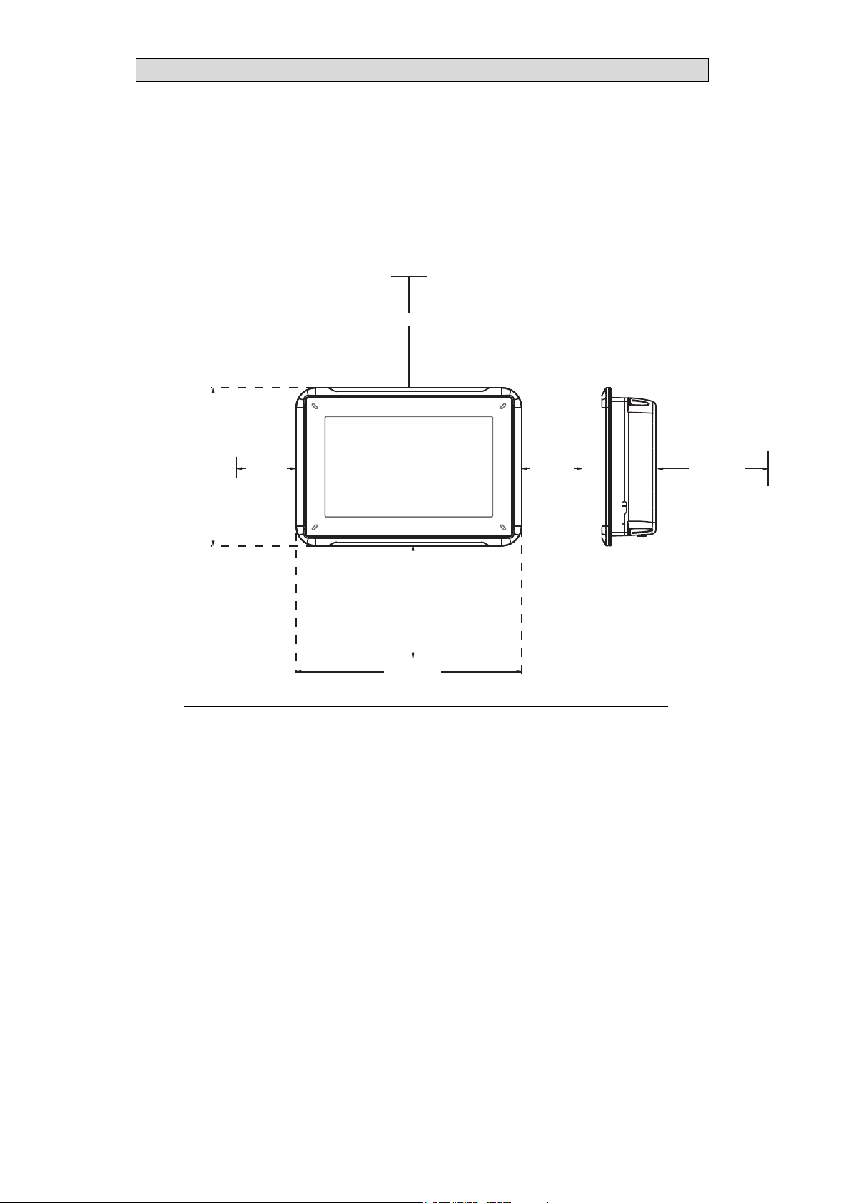
2.1 SpaceRequirements
• Maximum installation plate thickness: 11 mm
• Space requirements in millimeters when installing the operator panel:
100 mm
Installation
143 mm
100 mm
204 mm
Note:
Thedimensionsonthe drawingarenotproportional.
50 mm50 mm
100 mm
BeijerElectronics, MAEN118A
7
Page 8
2.2 InstallationProcess
The following is needed:
• A Phillips/slot screwdriver
1.
Unpackand check the delivery. If damage isfound, notify the supplier.
Note:
Placetheoperatorpanelona stablesurfaceduringinstallation.
Droppingthepanelorlettingitfallmaycausedamage.
2.
Usethecutoutdimensionsthatareincludedontheoutlinedrawing,found
in section Operator PanelDrawings and in the Technical Data table, to cut
a correct openingin the cabinet. A separate cut out drawing is available for
download from the Beijer Electronics web site.
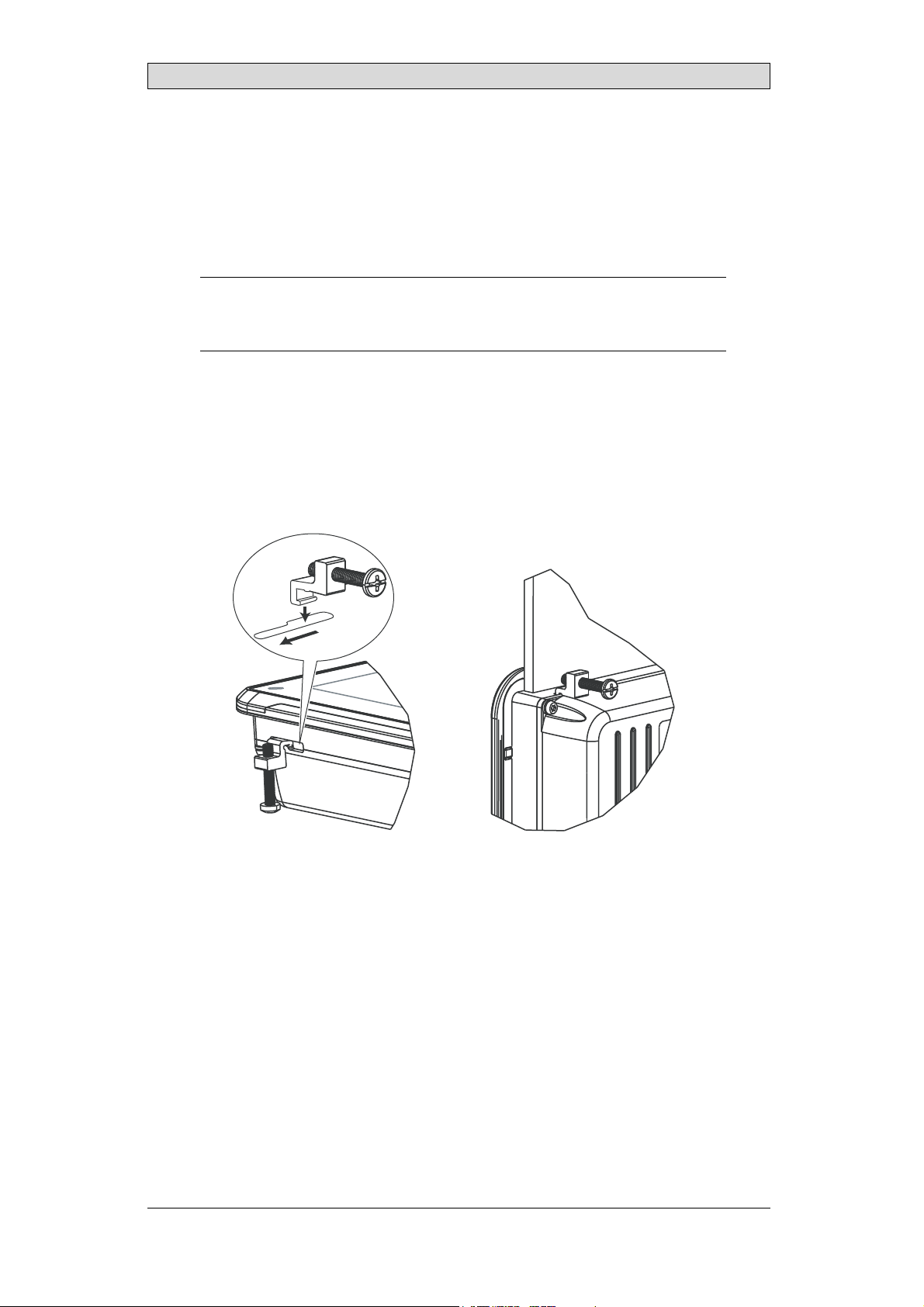
3.
Securethe operator panel in position using all the fastening holes and the
provided brackets and screws:
Installation
x 4 0.5 - 1.0 Nm
BeijerElectronics, MAEN118A
8
Page 9

Installation
4.
Connect the cables in the specified order, according to the drawing and steps
below.
Caution:
• Ensurethattheoperatorpanelandthecontrollersystemhavethesameelectrical
grounding(referencevoltagelevel),otherwiseerrorsincommunication may
occur.
• Theoperatorpanelmustbebroughttoambienttemperaturebeforeitisstarted
up. Ifcondensationforms,ensurethatthe operatorpanelisdrybeforeconnecting
ittothepower outlet.
• Ensurethatthev oltageandpolarityofthepowersourceiscorrect.
• Useonlyshieldedcommunicationcables.
• Separatehighvoltagecablesfromsignalandsupplycables.
B
RS232/
RS422/
RS485
24V DC
C
Power
Controller
24V DC
D
A
Ethernet
– Connect cable A.
– Connect cable B, using an M5 screw and a grounding conductor (as short
as possible) with a cross-section of minimum 2.5 mm
– Connect cable C.
– Connect cable D.
5.
Carefully remove the laminated film over the operator panel display, to avoid
2
.
static electricity that could damage the panel.
2.2.1 Connectionstoth
eController
Forinformation about the cables to be used when connecting the operator panel to
the controller, please refer to the help file for the driver in question.
BeijerElectronics, MAEN118A
9
Page 10

Installation
2.2.2 OtherConnectionsandPeripherals
Cables, peripheral equipment and accessories must be suitable for the application
and its environment. For further details or recommendations, please refer to the
supplier.
BeijerElectronics, MAEN118A
10
Page 11

Technical Data
3TechnicalData
Parameter iX T7AM
Frontpanel,W×H×D 204×143×7mm
Cutoutdimensions,
W×H
Mountingdepth 43mm(143mmincludingclearance)
Standalonemounting VESA75× 75
Frontpanelseal IP65
Rear panel seal IP 20
Touchscreen
material
Touchscreen
operations
Reverse side
material
Framematerial Powder-coatedaluminum
Weight 0.8 kg
Serialportfor
COM1RS232and
COM2RS422/RS485
Serialportfor
COM3RS232and
COM4RS422/RS485
Ethernet 1×10Base-T/100Base-T (shieldedRJ45)
USB 1×USBHost 2.0,maxoutputcurrent20 0 mA
Processor 400MHzARM9
Externalstorage
media
Flashmemory 128MBSSD(NANDFlash)
MemoryRAM 128MB(DDR2)
LED 1×blue/redsoftwareprogramm able
Real timeclock Yes
Battery BR2032Poly-carbonmonofluorideLithiumCoin
Powerconsumption
atratedvoltage
Fuse InternalDCfuse,2.0AT,5×20mm
Powersupply +24VDC(18-32VDC)
Display TFT-LCDwithLEDbacklight. 800×480pixels,64kcolors
Activeareaof
display, W×H
187×126mm
Note: MaximumscrewlengthforVESAmounting is4mm.
Usageoflongerscrewsmayleadtodamage.
Polyesteronglass,resistive.
Overlay: AutoflexEBA180L
1millionfingertouchoperations
Powder-coatedaluminum
9-pinD-subcontactwithRS232 RTS/CTS,chassis-mounted
femalewithstandardlockingscrews4-40UNC
9-pinD-subcontactwithRS232 RTS/CTS,chassis-mounted
femalewithstandardlockingscrews4-40UNC
1×SDcard(optional). OnlycompatiblewiththestandardSD
formatwithupto 2GBstoragecapacity.
6.0W
CE:Thepowersupplymustconformwiththe requirements
accordingtoIEC60950andIEC61558-2-4.
ULandcUL:Thepowersupply mustconformwiththe
requirementsforclassIIpowersupplies.
152.4×91.4mm
(1)
.
BeijerElectronics, MAEN118A
11
Page 12

Parameter iX T7AM
Operating
temperature
Storagetemperature -20°Cto+70°C
Relativehumidity <85%non-condensed
Approvalsand
certifications
(1)
SeesectionChemicalResistanceformoreinformation.
-10°Cto+60°C
Informationisavailableonthewebsite
www.beijerelectronics.com
Technical Data
BeijerElectronics, MAEN118A
12
Page 13

Chemical Resistance
4 ChemicalResistance
4.1 MetalCasing
The frame and casing material is powder-coated aluminum. This powder paint
withstands exposure to the following chemicals without visible change:
Aceticacid10% Phosphoricacid4%
Citricacid10% Phosphoricacid10%
Diesel Seawater
Distilledwater Sodiumchloride2%
Edibleoil Sodiumchloride20%
Fueloil Sulphuricacid20%
Hydrogenperoxide3% Tapwater
The powder paint shows limited resistance to the f
ollowing chemicals at room
temperature:
Butanol Nitricacid3%
Hydrochloricacid5% Nitricacid10%
Isopropylalcohol Phosphoricacid43%
Na-hypochlorite10% Turpentine
Note:
Ifexposuretoanyoftheabovechemicalsisdemanded,itisrecommendedtofirsttest
thechemicalinahiddenspotofthe metalcasing.
Thepowderpaintshowslittleornoresistancetothefollowingchemicalsatroom
temperature:
Aceticacid,conc. Methyl-ethylketone Toluene
Acetone Nitricacid30% Trichlorethylene
Ammonia5% Phenol Xylene
Ammonia,conc. Sodiumhydroxide5% 97octaneunleadedpetrol
Ethylacetate Sodiumhydroxide30% 98octaneleadedpet rol
BeijerElectronics, MAEN118A
13
Page 14

Chemical Resistance
4.2 TouchScreenandOverlay
4.2.1 AutoflexEBA180L
Autoflex EBA 180L covers the overlay surrounding the touch screen.
SolventResistance
Autoflex EBA 180L withstands exposure of more than 24 hours duration under
DIN42115Part2tothefollowingchemicalswithoutvisiblechange:
(1)
(1)
Phosphoricacid(<30%)
SBP60/95
(1)
Wisk
(1)
-
Acetonitrile DieselDowney/Lenor
Ajax/Viminsolution Ethanol Potassiumferricyanide
Alkalicarbonate
solution
Ammonia(<40%)
Aceticacid(<50%) Gumption
Arielpowderin
solution
Bleach
Castoroil Methanol Trichloroaceticacid(<50%)
Causticsoda(<40%)
Cuttingoil Paraffinoil Windex
Cyclohexanol Persilpowderin
Diacetonealcohol Petroleumspirit
(1)
(1)
(1)
(1)
Extremelyf
(1)
aintglossingof thetexturewas noted.
Glycerine Potassiumhydroxide(<30%)
Glycol PureTurpentine
(1)
Hydrochloricacid(<36%) Sulfuricacid(<10%)
Linseedoil Tomatoketchup
(1)
Nitricacid(<10%) WhiteSpirit
solution
(1)
Autoflex EBA 180L withstandsDIN 42 115 Part 2 exposure of up to 1 hour
duration to glacial acetic acid without visible change.
Autoflex EBA 180L is not resistant to high pressure steam at over 100 °C or the
following chemicals:
Concent
Conce
ratedmineralacids
ntratedcausticsolution
BeijerElectronics, MAEN118A
Benzyla
lenechloride
Methy
lcohol
14
Page 15

Chemical Resistance
4.2.2 TouchScreenSurface
The touch screen surface on the operator panel withstands exposure to the
following solvents without visible change:
Solvents Time
Acetone 10minutes
Isopropanol 10minutes
Toluene 5 hours
4.2.3 Autotex
It is recommended to use the Autoflex EB touch display protection film,that can
be ordered from Beijer Electronics.
OutdoorUse
In common with all polyester based films, Autoflex EB is not suitable for use in
conditions of long-term exposure to direct sunlight.
BeijerElectronics, MAEN118A
15
Page 16

Operator PanelDrawings
5 OperatorPanelDrawings
5.1 Connectors
COM 3/4LANCOM 1/2
1234
Pos. Connector Description
1 Powersupply +24VDC(18-32VDC)
2 COM1/2 CommunicationPorts
3 LAN 1 × 10/100Base-T(shieldedRJ-45)
4 COM3/4 CommunicationPorts
5.2 CommunicationPorts
Pin
1-
2 RS232RxD - RS232RxD 3 RS232TxD - RS232TxD 4 - RS422Rx+ - RS422Rx+
5 GND GND GND GND
6-
7 RS232RTS - - RS422RTS+
8 RS232CTS - - RS422 RTS9 - RS422Rx- - RS422Rx-
Note:
Inordertoutilizetwocommunicationportsonthesamephysicalport,theY-splitcable
CAB109mustbeused.
DrawingforexternalcableCAB109(drawing#Z7100-029E)is availableonthewebsite:
www.beijerelectronics.com
Serialport,9-pinfemale Serialport,9-pinfemale
COM1 COM2 COM3 COM4
RS422Tx+
RS485Tx+/Rx+
RS422Tx-
RS485Tx-/Rx-
-
-
RS422Tx+
RS485Tx+/Rx+
RS422Tx-
RS485Tx-/Rx-
BeijerElectronics, MAEN118A
16
Page 17

5.3 iXT7AMOutline
204
143
Operator PanelDrawings
COM3 RS232
COM4 RS422/RS485
Ethernet
COM1 RS232 /
COM2 RS422/RS485
24 V DC
max. 11 mm
7
43
SD memory
card slot
USB host
126
99
187 99
Expansion port
Note:
AStepCADfileis availableontheweb sitewww.beijerelectronics.com
BeijerElectronics, MAEN118A
17
Page 18

Additional Installation Tips
6 AdditionalInstallationTips
When experiencing communication problems in for example noisy environments
or when operating close to temperature limits, the following recommendations
are to be noticed.
6.1 GroundingtheOperatorPanel
Door
Operator panel
1
Ferrite core
6
3
2
5
4
Mounting plate in the cabinet
Power supply
24 V DC
5350
The operator panel’s mounting clamps do not provide a secure grounding
connection between the panel and the device cabinet, see 1 in drawing above.
1.
Connect a 2.5 mm
2
wire between the operator panel’s quick-connect plinth
and the panel’s chassis, see 2 in drawing above.
2.
Connect a 6 mm
2
or 4 mm2wire or grounding braid between the operator
panel’s chassis and the closest grounding point on the door, see 3 in drawing
above.
3.
Connect a strong but short groundingbraid between the door and the device
cabinet,see 4 in drawing above.
4.
Twist the cables onto the 24 V
cross-section of the cable
DC feed, see 5 in drawing above. Minimum
is 2.5 mm
2
.
2 turns around the ferrite core provide 4 times the suppression of 1 turn.
3 turns around the ferrite
core provide 9 times the suppression of 1 turn.
A ferrite core suppresses disturbancesto the 24 V feed, see 6 in drawingabove.
BeijerElectronics, MAEN118A
18
Page 19

Additional Installation Tips
Note:
Thegroundingwiresshouldbeshort andtheconductorshouldhavealarge area.
Along,thingroundingwirehasa veryhighimpedance(resistance)athighfrequencies
andwillnotguidedisturbancestotheground.
Multi-wireconductorsarebetterthansinglewireconductorswiththesamearea.
Abraidedconductorwirewiththe sameareais evenbetter. The bestisashort,thick
groundingbraid.
6.2 EthernetConnectioninthe OperatorPanel
Industrial Ethernet
RJ45
RJ45
1
RJ45
RJ45
Operator panel
Shielded
0.1 μF
250 V
RJ45
3
4
1-1
2-2
3-3
8-8
Short and
unshielded
5
Operator panel
RJ45
Operator panel
RJ45
Operator panel
RJ45
2
In some industrial units for Ethernet, the RJ45 contact’s shield is connectedto the
chassis via a capacitor,see 1 in d rawing above.
The operator panel’s Ethernet shield is directly connected to the chassis, see 2 in
drawing above.
1.
Check whether the otherEthernet unit has its shield directly grounded or
grounded via a capacitor.
Note:
Inmanycases,connectingtheshieldedEthernetcabling tothechassisatbothendsis
inappropriate. Humorgroundingloopscano ccur. Unshieldedcablingmayevenresult
infewercommunicationerrors.
BeijerElectronics, MAEN118A
19
Page 20

Additional Installation Tips
A good solution m a y be to use a shielded Ethernet cable, but to connect the shield
at one end only.
One option is to break the shield, see 3 in drawing above.
A more elegant method is to expand the shielded Ethernet cabling with a piece of
unshielded Ethernet cable, see 4 in drawing above.
The shield can be grounded via an external 0.1 μF/250 V plastic capacitor,see 5 in
drawing above. Thi s will c onnect the HF transients to ground.
BeijerElectronics, MAEN118A
20
Page 21

Additional Installation Tips
6.3 ToAchieveBetterEMCProtection
• Initially, use t he original cabling from Beijer Electronics prima rily.
• Useshielded cables for RS232 communication.
• Usetwisted pair and shielded cabling for RS422 and RS485.
• Usethe cablingintended for the bus type; Ethernet, Profibus, CC-Link,
CAN, Device Net etc.
• Install and connect according to applicable specifications for the relevant bus
standard.
• Useshielded cabling for Ethernet, preferably with foil and a braided shield.
• D-sub covers should be shielded, and the shield should be connected to the
cover 360° where the cable enters.
• Connect the shield at both ends.
Shielded cable
0.1 μF/250 V
Ground plane 1 Ground plane 2
Ground plate Ground plate in another building
Not same potential
With longer distances, thereis a risk that the ground potential may
In that case, the shield should only be connected at one end. A good
is to connect the other end of the shield to the ground via a
capacitor. Both ends are then connected to the ground in
connected to the ground at one end in terms of LF, thus av
0.1 μF/250 V plastic
terms of HF, but only
oiding the 50/60 Hz
be different.
alternative
grounding loops.
Metal cabinet Metal cabinet
Terminal or connector Terminal or connector
Cable clamp
in steel
Short distance
EMC cable gland
Shielded cable
1.
Usean EMC cable gland or regular plastic cable gland, remove the outer jacket
Shielded cable
Plastic cable gland
andconnecttheshieldtotheinstallation plate with a 360° metal cable clamp.
2.
Place the 24 V DC and communications cabling in one cable trunk/cable duct
and 230/380 V AC in another. If the cables need to b e crossed, cross them at
90° only. Avoid combining the cabling for stronger 24 V DC outputs with
the communication cabling.
Ferritecores that are snapped onto the shielded cabling may removeminor
disturbances. Large ferrite pieces that are snapped onto unshielded cabling and
where the wires go 2-4 times around the cores are approximately 5-25 times more
efficient.
BeijerElectronics, MAEN118A
21
Page 22

Additional Installation Tips
6.4 AmbientTemperature
The maximum ambient temperature for the operator panel is provided in the
specifications. The ambient temperature refers to the temperature in the device
cabinet which cools the operator panel’selectronics.
To p
50 °C inside
Operator
panel
30 °C outside
Middle
45 °C inside
Bottom
40 °C inside
Powe r
Powe r
Powe r
Axial fan
120 x 120 mm
Airflow
Inmostcases,theambienttemperaturefortheoperatorpanelissignificantly
higher than the device cabinet’s ambient temperature.
If the cabinet is tall and there are a number of heat-generating devices, the
temperature at the top of the cabinet w ill be considerably higher than the
theoretical temperature increase that would be expected. All electronics are
sensitivetoheat. Thelifespanofanelectrolyticcapacitoriscutinhalfwithan
8-10 °C increase in temperature. A 15-20 °C temperature increase results in a
quarter of the lifespan etc.
Rittal has a good program for estimating the anticipated average temperature in
the cabinet as well as a large program for controlling the temperature in the device
cabinet.
2
An enamel-coated steel cabinet has a radiant heat value of 5.5 W/m
and degrees
C.
Installing a fan inside the cabinet will even out the temperature, while moving air
provides considerably better cooling than still air.
Install the fan so that it sits in the cooler area and blows cold air against the operator
panel. If the fan is mounted at the top and sucks warm air upwards, the fan’s
ambient temperaturewill be higher,resulting in a shorter lifespan.
The operator panel’s loss effect = supply voltage x current. Virtually no power goes
to external users and no losseffects due to inputs.
BeijerElectronics, MAEN118A
22
Page 23

6.5 Safety
Most of the operator panels are fed with 24 V DC.
Power supply
1
2
3
230 V AC to 24 V DC
Power supply
230 V AC to 24 V DC
Power supply
230 V AC to 24 V DC
230 V AC
+24 V
0 V
4
+24 V
0 V
4
Distance?
+24 V
0 V
4
Operator panel
Operator panel
Operator panel
Small controller with expansion unit
COM1
COM100
Ch0
Ch1
Ch100
Ch101
5355
Additional Installation Tips
If a power supply that meets safety standards is used and only feeds the operator
panel, there is no problem. See 1 in drawing above.
However, if a 24 V unit that also feeds other units is used, there is reason to be
cautious, see 2 in drawing above. The operator panel does not have insulation
that meets safety requirements in the event of a potential short circuit between
230 V AC and 24 V DC. It is assumedthat the 24 V feed is secure, for example,
SELV according to EN 60950 (protection against electric shock) and UL 950.
Example:
Hereisanexamplethatexplainsw hy asecure24VDCfeedcan beruinedbymixing
24Vrelaycontacts with230VAC relaycontactsina smallercontroller. Checkthatthe
clearancesandcreepagedistancesbetween24VDCand230V ACfulfillEN60950or
UL950. Ifnot,inputa separate24Vunitintothe operatorpanel.
If there is a substa
230 V AC, it is OK t
ntial distance between the relay contacts for 24 V DC and
ousethesame24Vdevicesforallfeeds. See3indrawing
above.
Connect 0 V on the 24 V feed to the ground, see 4 in drawingabove. This offers
three advantages:
• Safety is incr
connection o
• Tr a n s i en t s
• No risk tha
is not unu
eased. The24Vfeedwillnotbeliveintheeventofafaulty
rshortcircuitbetween0V(24V)and230Vphase.
on the 24 V feed are connected to the ground.
t the 24 V feed is at a high level in relationship to the ground. This
sual since there is high static electricity.
BeijerElectronics, MAEN118A
23
Page 24

6.6 GalvanicIsolation
r
Additional Installation Tips
+24 V DC
0 V
Filter
DC/DC
galvanic isolation
1.5 m
Internal electronic
VCC
0 V (GND)
RS232RS422/485
USB
DC/AC
USB
Ethernet
CFL
The operator panel has galvanic isolation against the 24 V DC feed but no galvanic
isolation between the communication ports for RS232, RS422/485 and USB.
Only the Ethernet connection has galvanic isolation.
Operator panel Modular controller Printe
Power CPU COM COM2
RS422 RS232 USB
* *
**
*
Different ground potential
*
= Internal 0 V (GND) connection
***
*
PCPC
When a PC is connected to the operator panel, the panel’sinternal 0 V (GND) will
be connected to the protective ground via the PC.
A number of USB devices canhave the shield connected together with the
protective ground. Here, the operator panel’s 0 V (GND) is connected to the
protective ground when, for example, a USB memorystick, keyboard or similar
device is plugged in.
If a number of units are connected that have a 0 V and a ground connection, and
these are connected to various grounding points, there is a substantial risk of
problems. Grounding currents go through communication cables, the rear plate
of the controller,and internally in the operator panel, and can cause errors.
Use external units to improve communication and achieve galvanic isolation.
Westermo has good industry-standardinsulators that are also insulated from the
24 V DC feed.
Note:
Itisveryimportanttomake surethatthe24V feedintheexternalinsulationunitisnot
connectedtooneof thecommunicationoutlets. Ifitdoesnothave100 % insulation
againstthe24Vfeed,disturbancesandgroundingcurrentsfromthe0Vonthe24 V
sidewilldisruptcommunication.
Usingthistypeofunitsolvesone problembutcreatesalarger problem! Asubstandard
installationmayworknow,butproblemsmayarisewhenotherdevicesareconnected.
BeijerElectronics, MAEN118A
24
Page 25

Additional Installation Tips
6.7 CableandBusTerminationRS485
• If maximum transfer distan ce and maximum transfer speed is needed,
shielded and twisted pair cable should be used. The mutual capacitance
may not exceed 52.5 pF/m, and the cable area should be at least 0.25 mm
(AWG24).
• 0 V, the reference voltage for communication should be included in
the cabling. With two-way communication use two pairs; one pair for
communication and one pair for 0 V.
• The shield must be grounded at one end. The other end is usually grounded,
but with longer distances or when there is a difference in the ground potential,
theshieldshouldbeconnectedtothegroundvia0.1μF/250Vplastic
capacitor to preventground current in the braided shield. A number of
manufacturers recommend that the shield be grounded at each node. Various
manufacturers have different systems for bus termination.
Depending on the recipients’ design, the bus wires may be on the same level or
require pull-up or pull-down to ensure that no faulty signals are detected when the
bus is in resting mode (all transmitters aredisconnected).
2
BeijerElectronics, MAEN118A
25
 Loading...