

Page 1

iXT4A
InstallationManual
MAEN015F,2013-09
English
Page 2

Foreword
InstallationmanualforiXT4A
Foreword
All operator panels aredeveloped to satisfy the demands of human-machine
communication. Built-in functions such as displaying and controlling text,
dynamic indication, time channels, alarm and recipe handling are included.
The operator panel works primarily in an object-oriented way, making it easy to
understand and use. Configuration is carriedout on a PC using the iXDeveloper
configuration tool. The project can then be transferred and stored in theoperator
panel itself.
Various types of automation equipment such PLCs,servos or drives can be
connected tothe operator panels. In this manual, the term “thecontroller” refers
to the connected equipment.
This manual explains howto install the operator panel. Please refer to the
iX Developer reference manual for further information.
Order no: MAEN015F
Copyright ©2013-09 Beijer Electronics AB. All rights reserved.
The information in this document is subjecttochangewithoutnoticeandisprovidedasavailableatthe
time of printing. Beijer Electronics AB, including allits group companies, reserves the right to changeany
information without updating this publication. Beij er Electronics AB, including all its group companies,
assumesnoresponsibilityforanyerrorsthatmayappearinthisdocument. Readtheentireinstallation
manual prior to installing and using this equipment. Only qualified personnelmay install, operate or repair
this equipment. Beijer Electronics AB, includingall its group companies, are not responsiblefor modified,
altered or renovated equipment. Because the equipmenthas a wide range of applications, usersmust acquire
the appropriate knowledge to use the equipment properly in their specific applications. Persons responsible
for the application andthe equipment must themselves ensurethat each application is incompliance with
all relevant requirements, standards and legislationinrespecttoconfigurationandsafety. Onlypartsand
accessoriesmanufacturedaccordingto specificationsset byBeijer Electronics AB, including all its group
companies, may be used.
BEIJER ELE CTRONICS AB, INCLUDING ALL ITS GROUP
COMPANIES,SHALL NOTBE LIABLETO ANYONE FOR ANY
DIRECT, INDIRECT, SPECIAL, INCIDENTAL ORCONSEQUENTIAL
DAMAGES RESULTINGFROM THE INSTALLATION, USE OR
REPAIROF THIS EQUIPMENT, WHETHER ARISING IN TORT,
CONTRACT, OR OTHERWISE.BUYER'S SOLE REMEDY SHALL
BE THE REPAIR, REPLACEMENT, OR REFUND OF PURCHASE
PRICE, AND THE CHOICEOF THE APPLICABLE REMEDY SHALL
BE AT THE SOLE DISCRETION OF BEIJER ELECTRONICS AB,
INCLUDING ALL ITS GROUP COMPANIES.
BeijerElectronics, MAEN015F
Page 3

Contents
Contents
1 Safety Precautions ....................................................... 4
1.1 General ...........................................................
1.2 UL and cUL Installation .........................................
1.3 During Installation ..............................................
1.4 During Use .......................................................
1.5 Service and Maintenance ........................................
1.6 Dismantling and Scrapping .....................................
1.7 Appearance of Air in Touch Screen .............................
2 Installation ............................................................... 8
2.1 SpaceRequirements .............................................
2.2 Installation Process ..............................................
2.2.1 Connections tothe Controller ......... .........................
2.2.2 Other Connections and Peripherals .............................
3 TechnicalData ........................................................... 12
4 Chemical Resistance .................................................... 14
4.1 MetalCasing .....................................................
4.2 Touch Screen and Overlay .......................................
4.2.1 AutoflexEBA180L ..............................................
4.2.2 Touch ScreenSurface ........................................ ....
4.2.3 AutoflexEBA180L ..............................................
5 Operator PanelDrawings .............................................. 17
5.1 Connectors .......................................................
5.2 Communication Ports ...........................................
5.3 iX T4A Outline ..................................................
6 Additional Installation Tips .. . ......................................... 20
6.1 Grounding the Operator Panel .................................
6.2 Ethernet Connection in theOpe
6.3 To Achieve BetterEMC Protec
rator Panel ...................
tion .............................
6.4 AmbientTemperature ...........................................
6.5 Safety .............................................................
6.6 GalvanicIsolation ................................................
6.7 Cable and Bus Terminati
on RS485 .............................
11
11
14
15
15
16
16
17
17
19
20
21
23
24
25
26
27
4
4
6
6
6
6
7
8
9
BeijerElectronics, MAEN015F
Page 4

Safety Precautions
1SafetyPrecautions
Both the installer and the owner and/or operator of the operator panel must read
and understand this installation manual.
1.1 General
• Read thesafety precautions carefully.
• Check the delivery for transportationdamage. If damage is found, notify the
supplier as soon as possible.
• Do not use the operator panel inan environment with high explosive hazards.
• The supplier is not responsible for modified, altered orreconstructed
equipment.
• Use only parts and accessories manufactured according to specifications of
the supplier.
• Read the installation andoperating instructions carefully before installing,
using or repairing the operator panel.
• Neverallowfluids,metalfilingsorwiringdebristoenteranyopeningsinthe
operator panel. This may cause fire or electrical shock.
• Only qualified personnel may operate the operator panel.
• Storing the operator panelwhere the temperature is lower/higherthan
recommended inthis manual can cause theLCD displayliquid to
congeal/become isotopic.
• The LCD display liquid contains a powerfulirritant. In case of skin contact,
wash immediately with plenty of water. In case of eye contact, hold the eye
open,flushwithplentyofwaterandgetmedicalattention.
• Thefiguresinthismanualservesanillustrativepurpose. Becauseofthemany
variables associatedwith any particular installation, the supplier cannot
assume responsibilityfor actual use based on the figures.
• The supplier neither guarantees that the operator panel is suitablefor your
particular application, nor assumes responsibility for your product design,
installation or operation.
• It is recommended to turn on and shut down the operator panel at least once
before installing any components/cardsor before connecting the operator
panel to external devices, likefor exampleserial devices.
1.2 ULandcULInstallation
Caution:
ThissectionisonlyvalidforUL labelediXT4Apanels.
• This equipment is suitable for use in Class 2 non-hazardous locations only.
[Combinations ofequipment in your system are subject to investigation by
the local authority having jurisdiction at the time of installation].
BeijerElectronics, MAEN015F
4
Page 5
Safety Precautions
• All devices have to be supplied by a Class 2 power supply.
Warning:
Donotdisconnect equipmentunlesspowerhasbeenremovedortheareais
knowntobenon-hazardous
• ForCanada also AVERTISSEMENT – AVANT DE DECONNECTER
L’EQUIPEMENT, COUPER LE COURANT OUS’ASSURER QUE
L‘EMPLACEMENT EST DESIGNE NON DANGEREUX.
Warning:
OnlyULand cULapprovedexpansionunitsareallowedtobeconnectedto
theportdesignated “EXPANSION”. Atthemoment therearenosuchunits
evaluatedorallowed.
Warning:
Donotreplace expansionunitunlesspower hasbeenswitch
isknowntobenon-hazardous.
edofforthearea
• This product contains a battery; this must only be changed in anarea known
to be non-hazardous.
• Replace thebattery with aBR 2032 battery. Use of another type of battery
may present a risk of fire or explosion.
Warning:
Batterymayexplode ifmistreated. Donotrecharge, disassembleordispose
ofinfire.
• Foruse on a flat surface of a type 4X enclosureindoor use only.
• Use75 degree conductors only
• Use copper conductors only
• To make wiring connections to the power supply connector, follow the table
with cableand torque specifications below:
TerminalBlock No. WireSizeAWG TQLb.In.
X1/X100Phoenixconnectors AWG30–12 5–7
X1/X100Anytekconnectors AWG24–12 3.5
• These de
for the
panel m
vicesareClass2suppliedprogrammablecontrollers(industrialPCs)
use in industrial control equipment and are intended to be (front)
ounted (Type 1 and 4x for indoor use only).
BeijerElectronics, MAEN015F
5
Page 6

Safety Precautions
1.3 DuringInstallation
• The operator panel is designed for stationary installation on a plane surface,
where the followingconditions are fulfilled:
– no high explosive risks
– no strong magnetic fields
– no direct sunlight
– no large, suddentemperature changes
• Install the product accordingto theaccompanying installation instruc tions.
• Ground the product accordingto the accompanying installation instructions.
• Only qualified personnel may install the operator panel.
• Separate the high voltage, signal and supplycables.
• Make sure that the voltage andpolarity of the power source is c orrect before
connecting the product to the power outlet.
• Peripheralequipment mustbe appropriate for the application and location.
1.4 DuringUse
• Keep theoperator panel clean.
• Emergency stopand other safety functions maynot be control
operator panel.
• Do not use too much force or sharp objects when touching the
touchscreen etc.
led from the
keys,
1.5 ServiceandMaintenance
• Only qualified personnel should carry out repairs.
• The agreed warranty applies.
• Before carrying out any cleaning or maintenance operations, disconnect the
equipment from the electricalsupply.
• Clean the display and surrounding front coverwith a soft cloth andmild
detergent.
• Replacing thebattery incorrectly may result in explosion. Only use batteries
recommended bythe supplier. During the warranty period, the battery needs
to bereplaced by an authorized Beijer Electronics service center.
1.6 DismantlingandScrapping
• The operator panel or parts thereof shall be recycledaccording to local
regulations.
• The following components contain substances that might be hazardous
to health and theenvironment: lithium battery, electrolytic capacitorand
display.
BeijerElectronics, MAEN015F
6
Page 7

Safety Precautions
1.7 AppearanceofAirinTouchScreen
• Thelayerstructureofthetouchscreencontainsairandinrarecases
appearance of bubbles can arise. This is purelycosmetic and does not affect
any functio nality of the panel. The appearance can occurunder certain
environmental conditions such as temperature, humidity, and atmospheric
pressure.
BeijerElectronics, MAEN015F
7
Page 8
2Installation
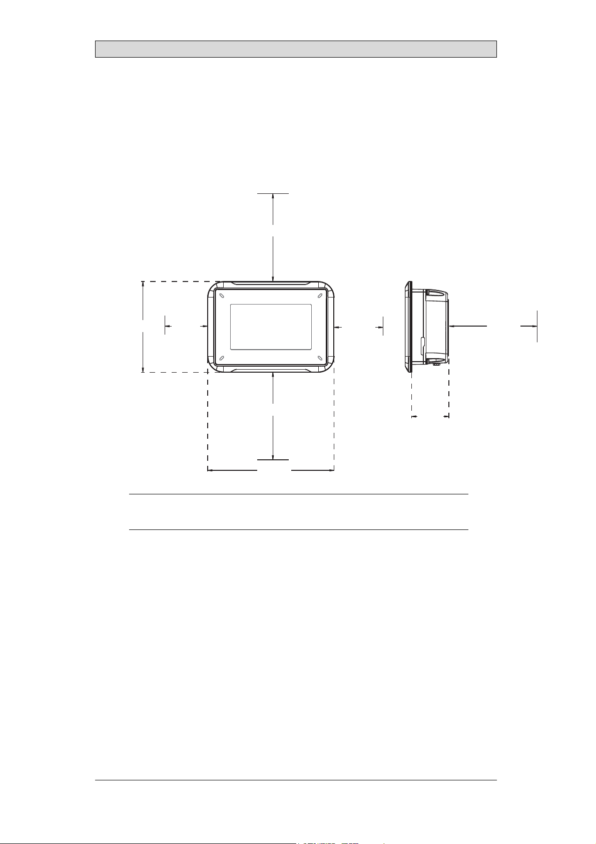
2.1 SpaceRequirements
• Maximum installation plate thickness: 11 mm
• Space requirements in millimeters when installing the operator panel:
100 mm
Installation
104 mm 50 mm
100 mm
145 mm
Note:
Thedimensionsonthedrawingarenotproportional.
50 mm
100 mm
43 mm
BeijerElectronics, MAEN015F
8
Page 9
2.2 InstallationProcess
The following is needed:
• A Phillips/slot screwdriver
1.
Unpackand check the delivery. If damage is found, notify the supplier.
Note:
Placetheoperator panelonastablesurfaceduringinstallation.
Droppingthe panelorlettingitfallmaycause damage.
2.
Usethecutoutdimensionsthatareincludedontheoutlinedrawing,found
in section Operator Panel Drawings and in the Technical Data table, to cut
a correct opening in the cabinet. A separate cut out drawing is available for
download from the Beijer Electronicsweb site.
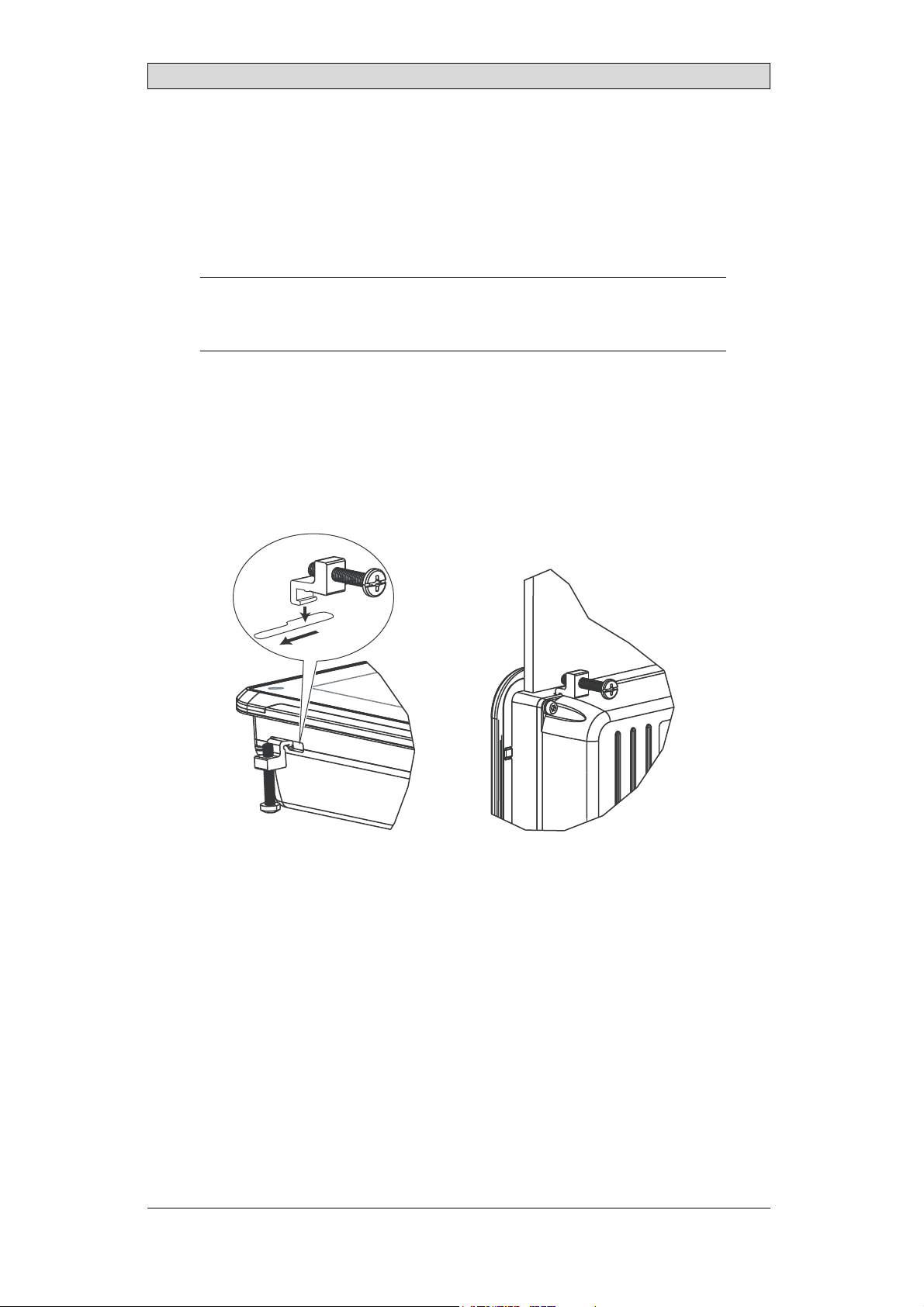
3.
Securethe operator panel in position using all the fastening holes and the
provided brackets and screws:
Installation
x 4 0.5 - 1.0 Nm
BeijerElectronics, MAEN015F
9
Page 10

Installation
4.
Connect the cables in thespecified order, according to the drawing and steps
below.
Caution:
• Ensurethattheo perator panelandthecontrollersystemhavethesameelectrical
grounding(referencevoltagelevel),otherwiseerrorsincommunicationmay
occur.
• Theoperatorpanelmustbebroughttoambient temperaturebeforeitisstarted
up. Ifcondensationforms,ensurethattheoperator panelisdrybeforeconnecting
ittothepoweroutlet.
• Ensurethatthevoltageand polarityofthepowersource iscorrect.
• Useonlyshieldedcommunicationcables.
• Separatehighvoltagecablesfromsignalandsupplycables.
B
RS232/
RS422/
RS485
24V DC
C
Power
Controller
24V DC
D
A
Ethernet
– Connect cable A.
– Connect cable B, using an M5 screw and a grounding con ductor(as short
as possible) with a cross-section of minimum 2.5 mm
– Connect cable C.
– Connect cable D. The recommended cross-section of the cable is
1.5 mm
5.
Carefully removethe laminated film over the operator panel display,to avoid
2
.
2
.
static electricity that coulddamage the panel.
Note:
OnlyforiXT4Apanelswithpartnumber 630000101:
Whenconnectingtheoperatorpaneltothepoweroutletforthe firsttime,make
surenotto interruptpowerforaminimumof48hoursinordertochargethebattery
completely. Afterthat, thebatterymay bechargedpartlyduringashorterperiod of
time.
BeijerElectronics, MAEN015F
10
Page 11

Installation
2.2.1 ConnectionstotheController
Forinformation about the cables to be usedwhen connecting the operator panel to
the controller, please refer to the help file for the driverin question.
2.2.2 OtherConnectionsandPeripherals
Cables, peripheral equipment and accessories must be suitablefor the application
and its environment. For further details or recommendations, please refer tothe
supplier.
BeijerElectronics, MAEN015F
11
Page 12

3TechnicalData
Parameter iX T4A
Frontpanel,W×H×D 145×103×7mm
Cutoutdimensions,
W×H
Mountingdepth 43mm(143 mmincludingclearance)
Standalonemounting VESA50×50
Frontpanelseal IP65
Rear panel seal IP 20
Touchscreen
material
Touchscreen
operations
Reverse side
material
Framematerial Powder-coatedaluminum
Weight 0.5 kg
Serialportfor
COM1RS232and
COM2RS422/RS485
Serialportfor
COM3RS232and
COM4RS422/RS485
Ethernet 1×10Base-T/ 100Base-T(shieldedRJ 45)
USB 1×USBHost2.0,maxoutputcurrent200mA
Processor 400MHzARM9
Externalstorage
media
Flashmemory
(application
memory)
MemoryRAM 128MB(DDR2)
LED 1× blue/redsoftwareprogrammable
Real timeclock Yes (onchip)
(2)
Battery
Power consumption
atratedvoltage
Fuse InternalDCfuse,2.0AT,5×20mm
128×87mm
Note: Maximum screwlengthforVESAmountingis4 mm.
Usageoflongerscrewsmayleadtodamage.
Polyesteronglass,resistive.
Overlay: AutoflexEBA180L
1millionfingertouchoperations
Powder-coated aluminum
9-pinD-subcontact withRS232RTS/CTS,chassis-mounted
femalewithstandardlockingscrew s 4-40UNC
9-pinD-subcontact withRS232RTS/CTS,chassis-mounted
femalewithstandardlockingscrew s 4-40UNC
1×SD card(optional). Onlycompatiblewiththe standardSD
formatwithupto2GBstoragecapacity.
128MBSSD(NANDFlash)
LithiumbatterytypeBR2032, soldered
orrechargeablebattery
MS920-SEorsimilar),soldered
3.6W
(1)
.
(2)
(SeikoInstrumentsPart No.
Technical Data
BeijerElectronics, MAEN015F
12
Page 13

Technical Data
Parameter iX T4A
Powersupply +24VDC(18-32VDC)
CE:Thepower supplymustconformwiththerequirements
accordingtoIEC60950andIEC61558-2-4.
ULandcUL: Thepowersupplymustconformwiththe
requirementsforclassIIpowersupplies.
Display TFT-LCDwithLEDbacklight. 480×272pixels,64kcolors
Activeareaof
display,W× H
Operating
temperature
Storagetemperature -20°C– +70°C
Relativehumidity 5-85% non-condensed
Approvalsand
certifications
(1)
SeesectionChemicalResistanceformoreinformation.
(2)
iXT4Apanelswithpartnumber630000101use arechargea
versionsuseaBR2032battery.
95.0×53.9mm
-10°C–+60°C
Informationis availableonthewebsite
www.beijerelectronics.com
blebattery. All other
BeijerElectronics, MAEN015F
13
Page 14

Chemical Resistance
4 ChemicalResistance
4.1 MetalCasing
The frame and casing material is powder-coated aluminum. This powder paint
withstands exposure to thefollowing chemicals without visible change:
Aceticacid10% Phosphoricacid4%
Citricacid10% Phosphoricacid10%
Diesel Seawater
Distilledwater Sodiumchloride2%
Edibleoil Sodiumchloride20%
Fueloil Sulphuricacid20%
Hydrogenperoxide3% Tapwater
The powder paint shows limited resistance to the f
ollowing chemicals at room
temperature:
Butanol Nitricacid3%
Hydrochloricacid5% Nitricacid10%
Isopropylalcohol Phosphoricacid43%
Na-hypochlorite10% Turpentine
Note:
Ifexposure toanyoftheabovechemicalsisdemanded,itisrecommendedtofirst test
thechemicalinahiddenspotofthemetalcasing.
Thepowderpaintshowslittleornoresistancetothefollowingchemicalsatroom
temperature:
Aceticacid,conc. Methyl-ethylketone Toluene
Acetone Nitricacid30% Trichlorethylene
Ammonia5% Phenol Xylene
Ammonia,conc. Sodiumhydroxide5% 97octaneunleaded petrol
Ethylacetate Sodiumhydroxide30% 98octaneleadedpetrol
BeijerElectronics, MAEN015F
14
Page 15

Chemical Resistance
4.2 TouchScreenandOverlay
4.2.1 AutoflexEBA180L
Autoflex EBA 180L covers the overlay surroundingthe touch screen.
SolventResistance
Autoflex EBA 180L withstands exposure of more than 24 hours duration under
DIN42115Part2tothefollowingchemicalswithoutvisiblechange:
(1)
(1)
Phosphoricacid(<30%)
SBP60/95
(1)
Wisk
(1)
-
Acetonitrile DieselDowney/Lenor
Ajax/Viminsolution Ethanol Potassiumferricyanide
Alkalicarbonate
solution
Ammonia(<40%)
Aceticacid(<50%) Gumption
Arielpowderin
solution
Bleach
Castoroil Methanol Trichloroaceticacid(<50%)
Causticsoda(<40%)
Cuttingoil Paraffinoil Windex
Cyclohexanol Persilpowderin
Diacetonealcohol Petroleumspirit
(1)
(1)
(1)
(1)
Extremelyf
(1)
aintglossing ofthetexturewasnoted.
Glycerine Potassiumhydroxide(<30%)
Glycol PureTurpentine
(1)
Hydrochloricacid(<36%) Sulfuricacid(<10%)
Linseedoil Tomatoketchup
(1)
Nitricacid(<10%) WhiteSpirit
solution
(1)
Autoflex EBA 180L withstands DIN 42 115 Part 2 exposure of up to 1 hour
duration toglacial acetic acid without visible change.
Autoflex EBA 180L is not resistant to high pressuresteam at over 100 °C or the
following chemicals:
Concent
Conce
ratedmineralacids
ntratedcausticsolution
BeijerElectronics, MAEN015F
Benzyla
lenechloride
Methy
lcohol
15
Page 16

Chemical Resistance
4.2.2 TouchScreenSurface
The touch screen surface on the operator panel withstands exposure to the
following solvents without visible change:
Solvents Time
Acetone 10minutes
Isopropanol 10minutes
Toluene 5 hours
4.2.3 AutoflexEBA180L
It is recommended to use the Autoflex EBA 180Ltouch display protection film,
that can be ordered from Beijer Electronics.
SolventResistance
Autoflex EBA 180L withstands exposure tothesamechemicalsasAutotexF157or
F207 according to section Autoflex EBA180L.
OutdoorUse
In common with allpolyester based films, Autoflex EBA 180L is not suitablefor
use in conditions of long-term exposure to direct sunlight.
BeijerElectronics, MAEN015F
16
Page 17

Operator Panel Drawings
5 OperatorPanelDrawings
5.1 Connectors
COM 3/4LANCOM 1/2
1234
Pos. Connector Description
1 Powersupply +24VDC(18-32VDC)
2 COM1/2 CommunicationPorts
3 LAN 1×10/100Base-T(shieldedRJ-45)
4 COM3/4 CommunicationPorts
5.2 CommunicationPorts
Pin
1-
2 RS232RxD - RS232RxD 3 RS232TxD - RS232TxD 4 - RS422Rx+ - RS422Rx+
5 GND GND GND GND
6-
7 RS232RTS - - RS422RTS+
8 RS232CTS - - RS422RTS9 - RS422Rx- - RS422Rx-
Note:
Inordertoutilizetwocommunicationportsonthesamephysicalport,theY-splitcable
CAB109mustbe used.
DrawingforexternalcableCAB109(drawing#Z7100-029E)isavailableon thewebsite:
www.beijerelectronics.com
Serialport,9-pin female Serialport,9-pin female
COM1 COM2 COM3 COM4
RS422Tx+
RS485Tx+/Rx+
RS422Tx-
RS485Tx-/Rx-
-
-
RS422Tx+
RS485Tx+/Rx+
RS422Tx-
RS485Tx-/Rx-
BeijerElectronics, MAEN015F
17
Page 18

Operator Panel Drawings
Note:
OnlyiXT4A panelswithpartnumber630000101areequippedwithterminated
COM-ports.
BeijerElectronics, MAEN015F
18
Page 19

5.3 iXT4AOutline
145
104
Operator Panel Drawings
COM3 RS 232 /
COM4 RS422/RS485
Ethernet
COM1 RS232 /
COM2 RS422/RS485
24 V DC
max. 11 mm
7
SD memory
card slot
USB host
43
9
87
99
99
Expansion port
128
Note:
AStepCADfile isavailableontheweb sitewww.beijerelectronics.com
BeijerElectronics, MAEN015F
19
Page 20

Additional Installation Tips
6 AdditionalInstallationTips
When experiencing communication problems in for example noisy environments
or when operating close to temperature limits,the following recommendations
are to be noticed.
6.1 GroundingtheOperatorPanel
Door
Operator panel
1
Ferrite core
6
3
2
5
4
Mounting plate in the cabinet
Power supply
24 V DC
5350
The operatorpanel’s mounting clamps do not provide a securegrounding
connection between the panel and the device cabinet, see 1 in drawing above.
1.
Connect a2.5 mm
2
wire between the operator panel’s quick-connect plinth
and the panel’s chassis, see2 in drawing above.
2.
Connect a 6 mm
2
or 4 mm2wire or grounding braid between the operator
panel’s chassis and the closest grounding point on the door, see 3 in drawing
above.
3.
Connect astrong but short grounding braid between the door and thedevice
cabinet,see 4 in drawingabove.
4.
Twist the cablesonto the 24 V
cross-section ofthe cable
DC feed, see 5in drawing above. Minimum
is 2.5 mm
2
.
2 turns around theferrite coreprovide 4 times the suppression of 1 turn.
3 turns around the ferrite
core provide 9 times the suppression of 1 turn.
A ferrite core suppresses disturbances to the 24 V feed, see 6 in drawing above.
BeijerElectronics, MAEN015F
20
Page 21

Additional Installation Tips
Note:
Thegroundingwiresshouldbeshortandtheconductorshould havealargearea.
Along,thin groundingwirehasa veryhighimpedance(resistance)athighfrequencies
andwillnot guidedisturbancestotheground.
Multi-wireconductorsare betterthansinglewireconductorswiththesamearea.
Abraided conductorwirewiththe samearea isevenbetter. Thebestisashort,thick
groundingbraid.
6.2 EthernetConnectioninthe OperatorPanel
Industrial Ethernet
RJ45
RJ45
1
RJ45
RJ45
Operator panel
Shielded
0.1 μF
250 V
RJ45
3
4
1-1
2-2
3-3
8-8
Short and
unshielded
5
Operator panel
RJ45
Operator panel
RJ45
Operator panel
RJ45
2
In some industrial units for Ethernet, the RJ45 contact’s shield is connected to the
chassis via a capacitor, see 1 in drawing above.
The o peratorpanel’s Ethernet shield is directly connected to the chassis, see 2 in
drawing above.
1.
Check w hetherthe other Ethernet unit has its shield directly grounded or
grounded via a capacitor.
Note:
Inmanycases,connectingtheshieldedEthernetcablingtothechassis atbothendsis
inappropriate. Hum orgroundingloopscanoccur. Unshieldedcabling mayevenresult
infewercommunicationerrors.
BeijerElectronics, MAEN015F
21
Page 22

Additional Installation Tips
A g ood solution may be to use a shielded Ethernetcable, but to connect the shield
at one end only.
One option is to break the shield, see 3 in drawing a bove.
A more elegant method is to expand the shielded Ethernet cabling witha piece of
unshielded Ethernet cable, see 4 in drawing above.
The shield can begrounded via an external 0.1 μF/250 V plastic capacitor,see 5 in
drawing above. This will connect theHF transients to ground.
BeijerElectronics, MAEN015F
22
Page 23

Additional Installation Tips
6.3 ToAchieveBetterEMCProtection
• Initially, usethe original cabling from BeijerElectronics primarily.
• Useshielded cables for RS232 communication.
• Usetwisted pair and shielded cabling for RS422 and RS485.
• Usethe cabling intendedfor the bus type; Ethernet, Profibus, CC-Link,
CAN, DeviceNet etc.
• Install and connect accordingto applicable specifications for the relevant bus
standard.
• Useshielded cabling for Ethernet,preferably withfoil and a braided shield.
• D-sub coversshould beshielded, and the shield shouldbe connected to the
cover 360° where the cable e nters.
• Connect the shield at both ends.
Shielded cable
0.1 μF/250 V
Ground plane 1 Ground plane 2
Ground plate Ground plate in another building
Not same potential
With longer distances, there is a riskthat the ground potential may
In that case, the shield should only be connected at one end. A good
is to connect the other end of the shield to the ground via a
capacitor. Both ends arethen connected to the ground in
connected to the ground at one end in termsof LF, thus av
0.1 μF/250 V plastic
terms of HF, but only
oiding the 50/60 Hz
be different.
alternative
grounding loops.
Metal cabinet Metal cabinet
Terminal or connector Terminal or connector
Cable clamp
in steel
Short distance
EMC cable gland
Shielded cable
1.
Usean EMC cable gland or regular plastic cable gland, removethe outer jacket
Shielded cable
Plastic cable gland
andconnecttheshieldtotheinstallation plate with a 360° metal cable clamp.
2.
Place the 24 V DC and communicationscabling in one cable trunk/cable duct
and 230/380 V ACin another. If the cables need to be crossed, cross them at
90° only. Avoidcombining the cabling for stronger 24 V DC outputs with
the communication cabling.
Ferritecores that are snapped onto the shielded cabling may remove minor
disturbances. Large ferrite pieces that are snapped onto unshielded cabling and
where the wires go 2-4 times around the cores are approximately 5-25 times more
efficient.
BeijerElectronics, MAEN015F
23
Page 24

Additional Installation Tips
6.4 AmbientTemperature
The maximum ambient temperaturefor the operator panel is provided in the
specifications. The ambient temperature refers to the temperature in the device
cabinet whichcools the operator panel’s electronics.
To p
50 °C inside
Operator
panel
30 °C outside
Middle
45 °C inside
Bottom
40 °C inside
Powe r
Powe r
Powe r
Axial fan
120 x 120 mm
Airflow
Inmostcases,theambienttemperaturefortheoperatorpanelissignificantly
higher than the devicecabinet’s ambient temperature.
If the cabinet is tall and there area number of heat-generating devices, the
temperature at the top of the cabinet will be considerably higher than the
theoretical temperature increase thatwould be expected. All e lectronicsare
sensitivetoheat. Thelifespanofanelectrolyticcapacitoriscutinhalfwithan
8-10 °Cincrease in temperature. A 15-20 °C temperature increaseresults in a
quarter of the lifespan etc.
Rittal has a good program for estimating the anticipatedaverage temperature in
the cabinet as well as a large program for controlling the temperature in the device
cabinet.
2
An enamel-coated steel cabinet has a radiant heat value of 5.5 W/m
and degrees
C.
Installing a fan inside the cabinet will even out the temperature,while movingair
provides considerably better cooling than still air.
Install the fan so that it sits in the cooler area and blows coldair against the operator
panel. If the fan is mounted at the top and sucks warm airupwards, thefan’s
ambient temperature will be high er, resultingin a shorterlifespan.
The operator panel’s loss effect = supplyvoltage x current. Virtually no powergoes
to external users and no loss effects due to inputs.
BeijerElectronics, MAEN015F
24
Page 25

6.5 Safety
Most of the operator panels are fed with 24 V DC.
Power supply
1
2
3
230 V AC to 24 V DC
Power supply
230 V AC to 24 V DC
Power supply
230 V AC to 24 V DC
230 V AC
+24 V
0 V
4
+24 V
0 V
4
Distance?
+24 V
0 V
4
Operator panel
Operator panel
Operator panel
Small controller with expansion unit
COM1
COM100
Ch0
Ch1
Ch100
Ch101
5355
Additional Installation Tips
If a power supply that meetssafety standardsis used and only feeds the operator
panel, there is noproblem. See 1 in drawing above.
However, if a 24 V unit that also feedsother units is used, there is reason to be
cautious, see2 in drawing above. The operator panel does not have insulation
that meets safety requirements in the event of a potential short circuit between
230 VAC and 24 V DC.It is assumed that the24 V feed is secure, for example,
SELV accordingto EN 60950 (protection againstelectric shock) and UL 950.
Example:
Hereisan examplethatexplainswhyasecure24VDCfeedcanberuinedbymixing
24Vrelaycontactswith 230VAC relaycontactsinasmallercontroller. Checkthatthe
clearancesandcreepagedistancesbetween24VDCand230VAC fulfillEN60950or
UL950. Ifnot, inputaseparate24Vunitintotheoperatorpanel.
If thereis a substa
230 V AC, it is OK t
ntial distance between the relay contacts for 24 V DC and
ousethesame24Vdevicesforallfeeds. See3indrawing
above.
Connect 0 V on the 24 V feed to the ground, see4 in drawing above. This offers
three advantages:
• Safety is incr
connection o
• Tr a nsi e nt s
• No risk tha
is notunu
eased. The24Vfeedwillnotbeliveintheeventofafaulty
rshortcircuitbetween0V(24V)and230Vphase.
on the24 V feed are connected to the ground.
t the 24 V feed is at a high level in relationship to the ground. This
sual si nce there ishigh static electricity.
BeijerElectronics, MAEN015F
25
Page 26

6.6 GalvanicIsolation
r
Additional Installation Tips
+24 V DC
0 V
Filter
DC/DC
galvanic isolation
1.5 m
Internal electronic
VCC
0 V (GND)
RS232RS422/485
USB
DC/AC
USB
Ethernet
CFL
The operator panel has galvanic isolation against the 24 V DC feed but nogalvanic
isolation between the communication portsfor RS232, RS422/485 and USB.
Only the Ethernet connection has galvanic isolation.
Operator panel Modular controller Printe
Power CPU COM COM2
RS422 RS232 USB
* *
**
*
Different ground potential
*
= Internal 0 V (GND) connection
***
*
PCPC
When aPC is connected to the operator panel, the panel’s internal 0 V (GND) will
be connected to the protective ground via the PC.
A number of USB devices can havethe shield connectedtogether with the
protective ground. Here,the operator panel’s0 V (GND) isconnected to the
protective ground when, for example, a USB memory stick, keyboard or similar
device is plugged in.
If a number of units are connected that havea 0 V and aground connection, and
these areconnected to various grounding points, there is a substantial risk of
problems. Grounding currentsgo through communication cables, the rear plate
of thecontroller,and internally in the operator panel, and can cause errors.
Use external units toimprove communication and achieve galvanic isolation.
Westermo has good industry-standard insulators that are also insulated from the
24 V DC feed.
Note:
Itisvery importanttomakesurethatthe24Vfeedin theexternalinsulationunitisnot
connectedtooneofthecommunicationoutlets. Ifitdoesnothave100%insulation
againstthe24 Vfeed,disturbancesandgroundingcurrentsfromthe0Vonthe24V
sidewilldisruptcommunication.
Usingthistypeofunitsolveso ne problembutcreates alargerproblem! A substandard
installationmayworknow,butproblemsmayarisewhenotherdevicesareconnected.
BeijerElectronics, MAEN015F
26
Page 27

Additional Installation Tips
6.7 CableandBusTerminationRS485
• If maximumtransfer distance and maximum transfer speed is needed,
shielded and twisted pair cable should be used. The mutual capacitance
may notexceed 52.5 pF/m, and the cable area shouldbe at least 0.25 mm
(AWG 24).
• 0 V,the reference voltage for communication should be included in
the cabling. With two-way communication use two pairs; one pair for
communication andone pair for 0 V.
• The shield must be grounded at one end. The other end is usually grounded,
but with longer distances or when there is adifference in the ground potential,
theshieldshouldbeconnectedtothegroundvia0.1μF/250Vplastic
capacitor to prevent ground currentin thebraided shield. A number of
manufacturers recommend that the shield be grounded ateach node. Various
manufacturers have different systems for bus termination.
Depending on the recipients’ design, the bus wiresmay be on the same level or
require pull-up or pull-down to ensure that no faulty signals are detected when the
bus is in resting mode (all transmitters are disconnected).
2
BeijerElectronics, MAEN015F
27
Page 28

Headoffice
BeijerElectronicsAB
Box426
20124Malmö,Sweden
www.beijerelectronics.com/+4640358600
 Loading...