

Page 1

iXT21C
InstallationManual
MAEN084D,2013-09
English
Page 2

Foreword
Installationmanual foriXT21C
Foreword
All operator panelsare developed to satisfythe demands ofhuman-machine
communication. Built-in functionssuch as displayingand controlling text,
dynamic indication, timechannels, alarm andrecipe handling areincluded.
The operator panelworks primarily in an object-oriented way,making it easy to
understand and use. Configuration is carried out on a PC using the iX Developer
configuration tool. The project can then be transferred and stored in the operator
panel itself.
Various types of automation equipment such PLCs, servosor drives can be
connected to the operator panels. In this manual,the term “thecontroller” refers
to the connected equipment.
This manual explains how to install the operator panel. Please refer to the
iX Developer reference manual for further information.
Order no: MAEN084D
Copyright © 2013-09 Beijer Electronics AB. All rights reserved.
The information in this documentissubjecttochangewithoutnoticeandisprovidedasavailableatthe
time of printing. Beijer Electronics AB, including all its group companies, reservestherighttochangeany
information without updating this publication. Beijer Electronics AB, including all its group companies,
assumesnoresponsibilityforanyerrorsthatmayappearinthisdocument. Readtheentireinstallation
manual prior to installing and using this equipment. Only qualified personnel may install, operate or repair
this equipment. Beijer Electronics AB, including all its group companies, are not responsible for modified,
altered or renovatedequipment. Because the equipment has a wide range of applications, users must acquire
the appropriate knowledge to use the equipment properly in their specific applications. Persons responsible
for the application and the equipment must themselves ensure that each application is in co m pliancewith
all relevant requirements,standards and legislationinrespecttoconfigurationandsafety. Onlypartsand
accessoriesmanufacturedaccording to specifications set by Beijer ElectronicsAB,includingallitsgroup
companies, maybeused.
BEIJER ELECTRONICS AB, INCLUDING ALL ITS GROUP
COMPANIES,SHALL NOT BE LIABLE TOANYONE FOR ANY
DIRECT, INDIRECT, SPECIAL, INCIDENTALOR CONSEQUENTIAL
DAMAGES RESULTINGFROMTHE INSTALLATION, USE OR
REPAIROF THIS EQUIPMENT, WHETHER ARISING IN TORT,
CONTRACT, OR OTHERWISE. BUYER'S SOLE REMEDY SHALL
BE THE REPAIR,REPLACEMENT, OR REFUND OF PURCHASE
PRICE, AND THE CHOICE OF THE APPLICABLE REMEDY SHALL
BE AT THE SOLE DISCRETION OF BEIJER ELECTRONICSAB,
INCLUDING ALL ITS GROUP COMPANIES.
BeijerElectronics, MAEN084D
Page 3

Contents
Contents
1 Safety Precautions ....................................................... 4
1.1 General ...........................................................
1.2 DuringInstallation ..............................................
1.3 During Use .......................................................
1.4 Service and Maintenance ........................................
1.5 Dismantling and Scrapping .....................................
1.6 Appearance of Air in Touch Screen .............................
2 Installation ............................................................... 6
2.1 Space Requirements .............................................
2.2 Installation Process ..............................................
2.2.1 Connectionstothe Controller .............................. ....
2.2.2 Other ConnectionsandPeripherals ...................... .......
3 Hardware Replacement ................................................. 10
3.1 Replacing the Fanand Filter .....................................
3.2 Replacing the 2.5” SATA Mass Storage .........................
3.3 Replacing a CompactFlashorCFast Memory Card ...........
3.4 Replacing theBattery ............................................
4 Technical Data ........................................................... 16
5 Chemical Resistance .................................................... 18
5.1 Metal Casing .....................................................
5.2 Touch Screen and Overlay .......................................
5.2.1 AutotexF157/207 ........................................... ....
5.2.2 TouchScreen Surface ............. ...............................
5.2.3 Autotex ......... .................................................
6 OperatorPanel Drawings .............................................. 21
6.1 Connectors .......................................................
6.2 CommunicationPorts ...........................................
6.3 iX T21C Outline .................................................
7 Additional Installation Tips ............................................ 25
7.1 Grounding the Operator Panel .................................
7.2 Ethernet ConnectionintheOperator Panel ...................
7.3 To Achieve Better EMC Protection .............................
7.4 Ambient Temperature ...........................................
7.5 Safety .............................................................
7.6 Cable and Bus Termination RS485 .............................
7.7 BootPriority .....................................................
7.8 EnteringBIOS ...................................................
7.9 Reset Switch ......................................................
9
9
10
12
14
15
18
19
19
20
20
21
21
23
25
26
28
29
30
31
32
32
33
4
4
5
5
5
5
6
7
BeijerElectronics, MAEN084D
Page 4

Safety Precautions
1SafetyPrecautions
Both the installer and the owner and/or operator of the operator panel must read
and understand this installation manual.
1.1 General
• Read the safety precautions carefully.
• Check the delivery for transportation damage. If damage is found, notify the
supplier as soon as possible.
• Do not use the operator panel in an environment with high explosive hazards.
• The supplier is not responsible formodified, altered or reconstructed
equipment.
• Use only parts and accessories manufactured accordingto specifications of
the supplier.
• Read the installation and operating instructionscarefully before installing,
using or repairing the operator panel.
• Neverallowfluids,metalfilingsorwiringdebristoenteranyopeningsinthe
operator panel. This may cause fire or electrical shock.
• Only qualified personnel may operatethe operator panel.
• Storing the operator panel where the temperature is lower/higher than
recommended in this manual can cause the LCD display liquid to
congeal/become isotopic.
• The LCD display liquid contains a powerful irritant. In case of skin contact,
wash immediately with plenty of water. In case of eye contact, hold the eye
open,flushwithplentyofwaterandgetmedicalattention.
• Thefiguresinthismanualservesanillustrativepurpose. Becauseofthemany
variables associated with any particular installation, the supplier cannot
assume responsibility for actual use based on the figures.
• The supplier neither guarantees that the operator panel is suitable for your
particular application, nor assumes responsibility for your product design,
installation or operation.
• It is recommended to turn on and shut down the operator panel at least once
before installing any components/cards or bef ore connecting the operator
panel to externaldevices, like for example serial devices.
1.2 DuringInstallation
• The operator panel is designed for stationar y installation on a plane surface,
where the following conditions are fulfilled:
– no high explosive risks
– no strong magnetic fields
– no direct sunlight
– no large, sudden temperature changes
• Install the product according to the accompanying installation instructions.
• Ground the product according to the accompanying installation instr u ctions.
• Only qualified personnel may install the operato r panel.
• Separate the high voltage, signal and supply cables.
• Make sure that the voltage and polarity of the power source i s correct before
connecting the product to the power outlet.
BeijerElectronics, MAEN084D
4
Page 5

Safety Precautions
• Peripheralequipment must be appropriate for the application and location.
1.3 DuringUse
• Keep the operator panel clean.
• Emergency stop and other safety functions may not be controlled from the
operator panel.
• Do not use too much force or sharp objects when touching thekeys,
touchscreen etc.
1.4 ServiceandMaintenance
• Only qualified personnel should carryout repairs.
• The agreed warranty applies.
• Before carrying out any cleaning or maintenance operations, disconnect the
equipment from the electrical supply.
• Clean the display a nd surrounding front cover with a soft cloth and mild
detergent.
• Replacing the battery incorrectly mayresult in explosion. Only use batteries
recommended by the supplier. During the warranty period, the battery needs
to be replaced by an authorized Beijer Electronics service center.
• The unit can be reset by using the reset switch located behind the fan.
1.5 DismantlingandScrapping
• The operator panel or parts thereof shall be r
regulations.
• The following components contain substan
to health and the environment: lithium ba
display.
ecycled according to local
ces that might be hazardous
ttery,electrolytic capacitor and
1.6 AppearanceofAirinTouchScreen
• Thelayerstructureofthetouchscreencontainsairandinrarecases
appearance of bubbles can arise. This is purely cosmetic and does not affect
any functionality of the panel. T he appearance can occur under certain
environmental conditions such as temperature, humidity,and atmospheric
pressure.
BeijerElectronics, MAEN084D
5
Page 6
2Installation
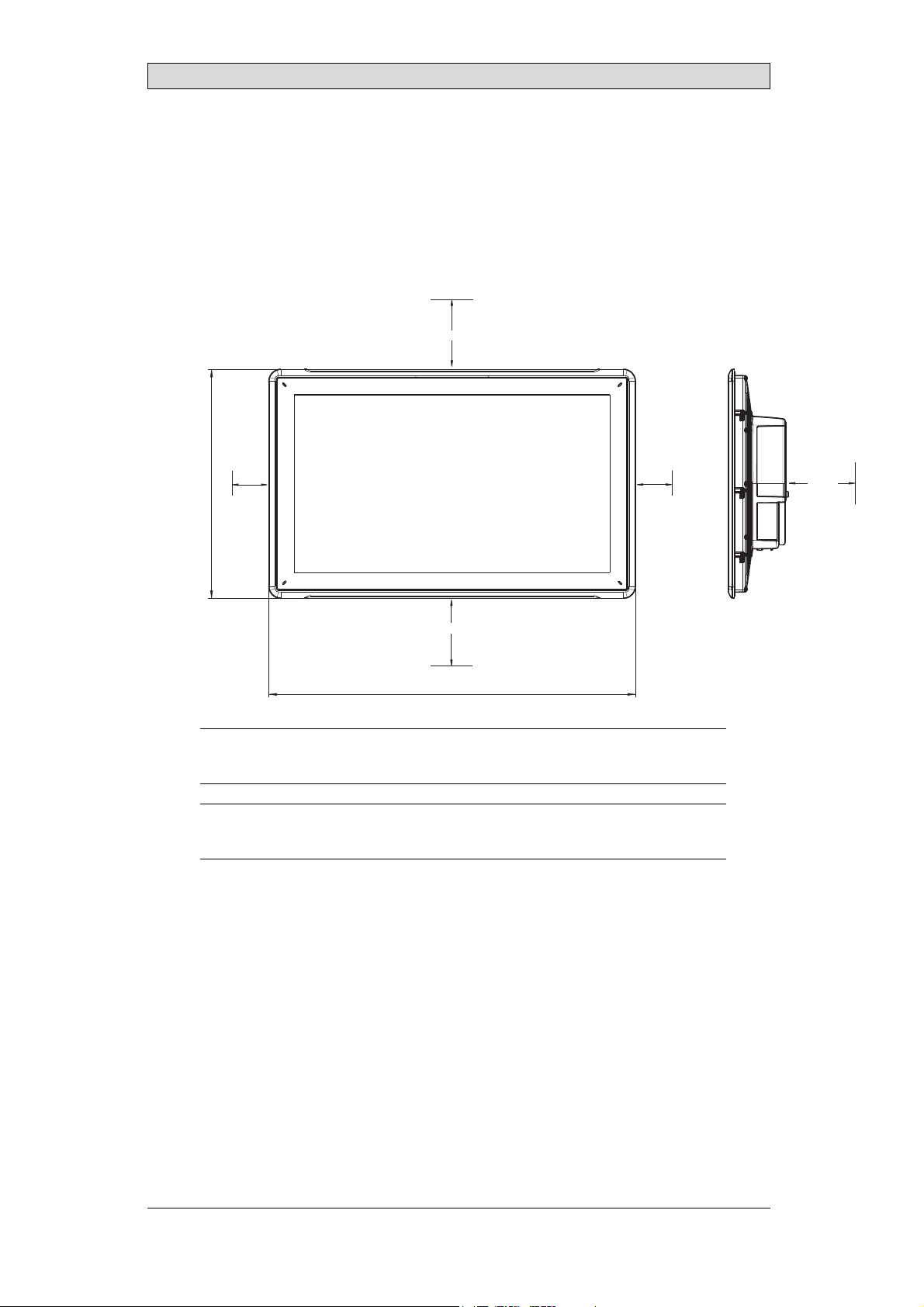
2.1 SpaceRequirements
• Maximum installation plate thickness: 8 mm
• Space requirements in millimeters when installing the operator panel:
100 mm
Installation
347 mm
50 mm
100 mm
556 mm
Note:
Thedimensionsonthedrawingare
Caution:
Theopeningsontheenclosureare forairconvection. Donotcovertheseopenings.
notproportional.
50 mm
100 mm
BeijerElectronics, MAEN084D
6
Page 7
2.2 InstallationProcess
The following is needed:
• ATorxTX7screwdriver
1.
Unpackand check the delivery. If damage is found, notify the supplier.
Note:
Placetheoperatorpanelonastablesurfaceduringinstallation.
Droppingthepanelorlettingitfall maycausedamage.
2.
Usethecutoutdimensionsthatareincludedontheoutlinedrawing,found
in section Operator Panel Drawings and in the Technical Data table, to cut
a correct opening in the cabinet. A separate cut out drawing is available for
download from the Beijer Electronics web site.
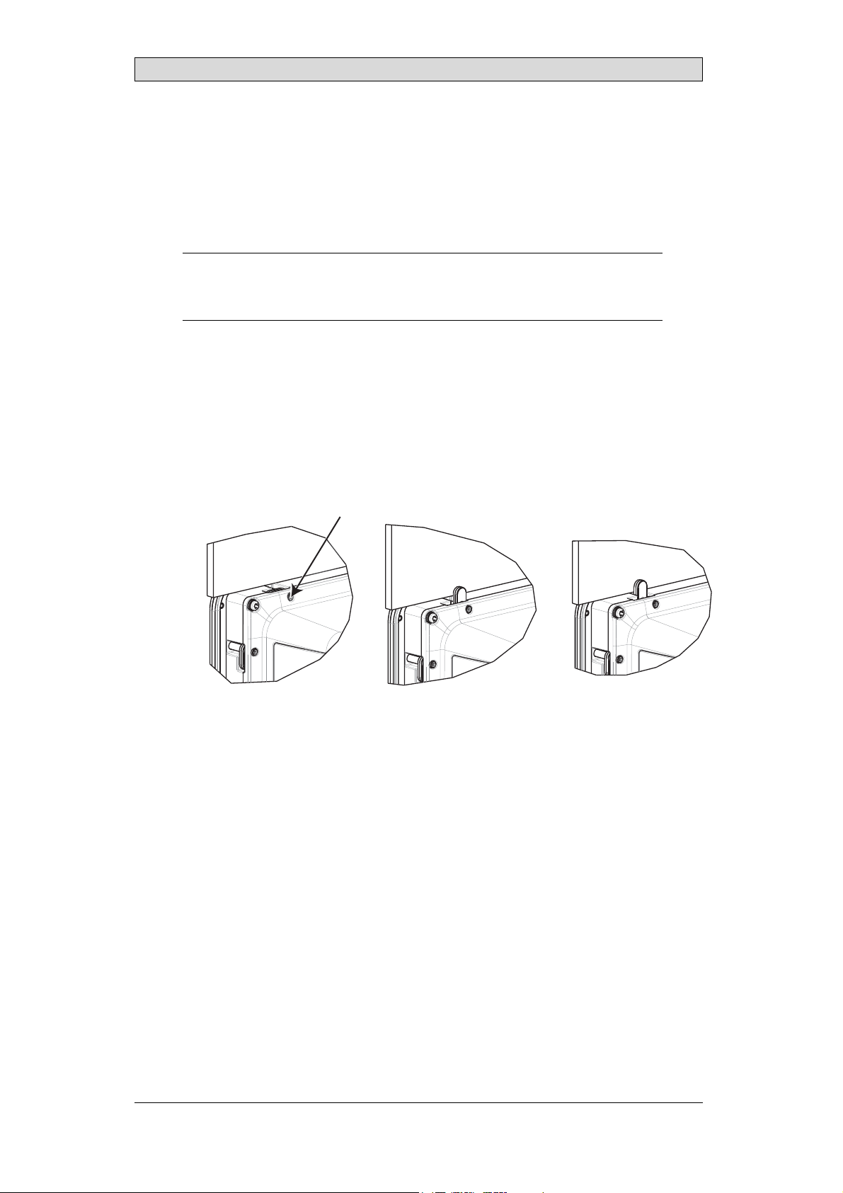
3.
Secure the operator panel in position by screwing the M4 Torx screw,allowing
the built-in bracket to tighten against the panel:
M4 x 20.7
0.4 Nm
Installation
BeijerElectronics, MAEN084D
7
Page 8
Installation
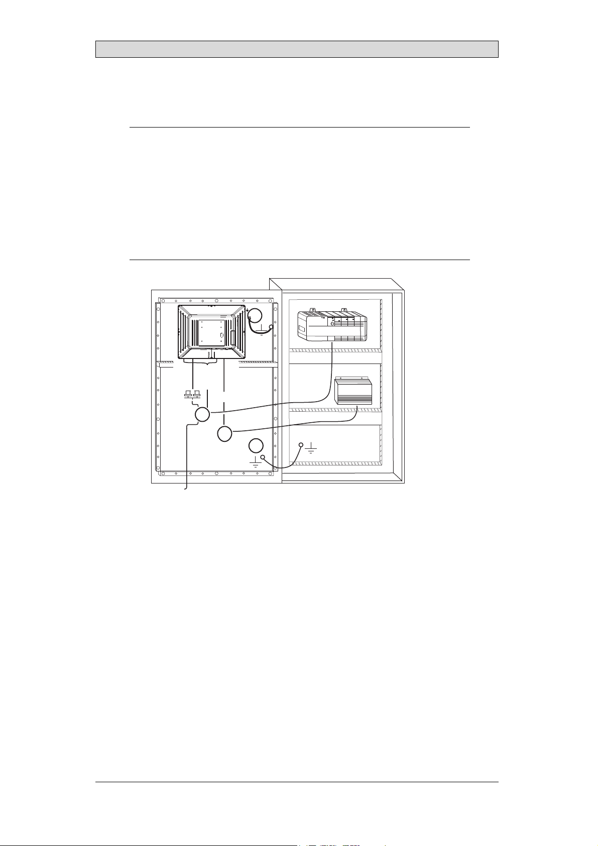
4.
Connect the cables in the specified order, according to the drawing and steps
below.
Caution:
• Ensurethattheoperatorpanelandthecontrollersystemhavethesameelectrical
grounding(referencevoltagelevel),otherwiseerrorsincommunicationmay
occur.
• Theoperatorpanelmustbebroughttoambienttemperaturebefore itisstarted
up. Ifcondensationforms,ensurethatthe operatorpanelisdrybefore connecting
ittothepoweroutlet.
• Ensurethatthevoltageandpolarityofthe powersourceis correct.
• Useonlyshieldedcommunicationcables.
• Separatehighvoltagecablesfromsignalandsupplycables.
B
RS232/
RS422/
RS485
24V DC
C
Power
Controller
24V DC
D
A
Ethernet
– Connect cable A.
– Connect cable B, using an M5 screw and a grounding con ductor(as short
as possible) with a cross-section of minimum 2.5 mm
– Connect cable C .
– Connect cable D. The recommended cross-section of the cable is
2.5 mm
5.
Carefully remove the laminated film over the operator panel display, to avoid
2
.
2
.
static electricity that could damage the panel.
BeijerElectronics, MAEN084D
8
Page 9

Installation
2.2.1 ConnectionstotheController
Forinformation about the cables to be used when connecting the operator panel to
the controller, please refer to the help file for the driver in question.
2.2.2 OtherConnectionsandPeripherals
Cables, peripheralequipment and accessories must be suitable f or the application
and its environment. For further details or recommendations, please refer to the
supplier.
BeijerElectronics, MAEN084D
9
Page 10
Hardware Replacement
3 HardwareReplacement
This section contains instructions on how to replace operator panel hardware.
Only components included in the latest bill of materialand spare parts list are
allowed.
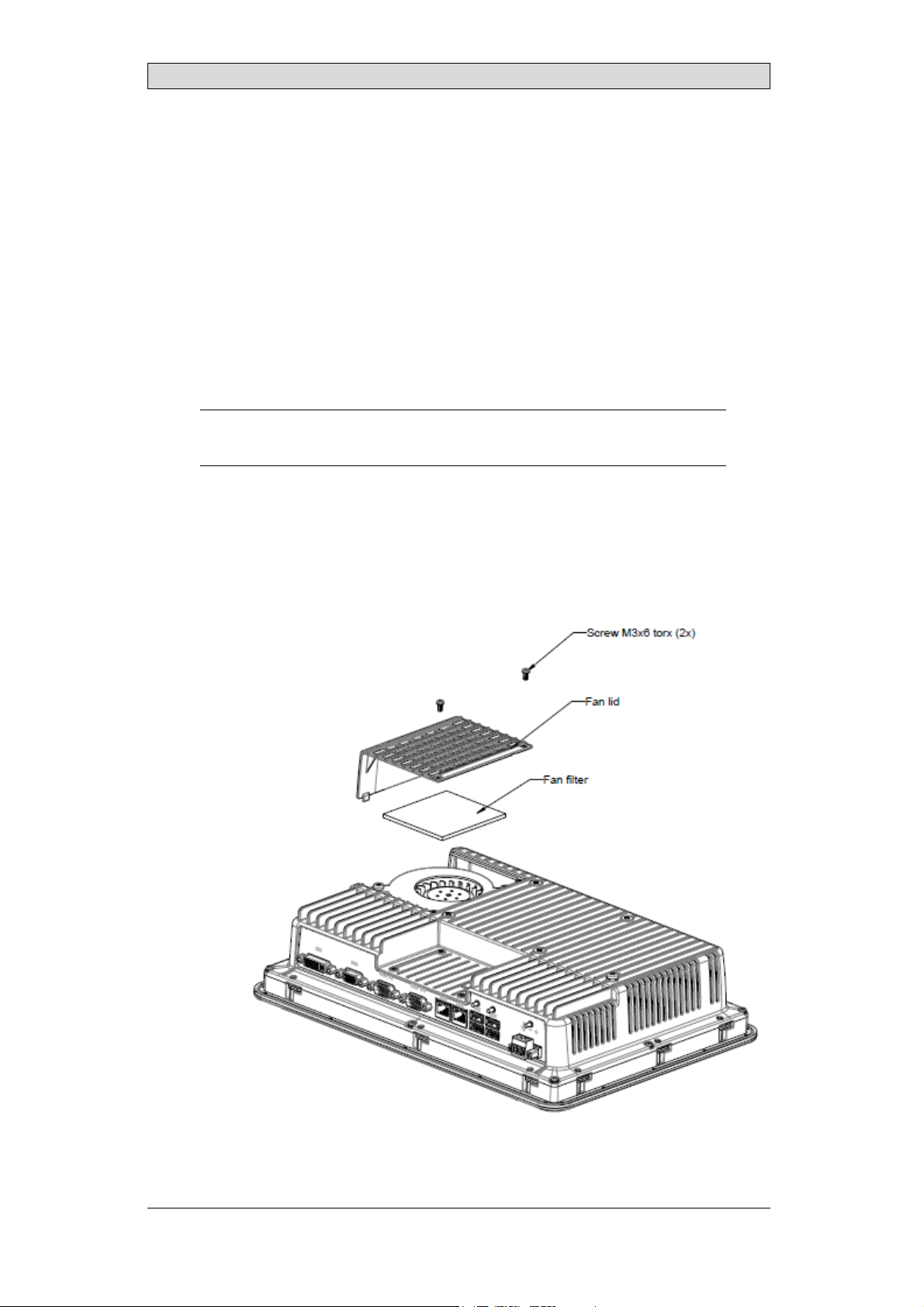
3.1 ReplacingtheFanandFilter
The following is needed:
• Anewfan
• A Torx TX10 and a TX20 screwdriver
Note:
MakesuretouseadequateESDprotection.
Followthe steps below toreplace the fan and fan filter:
1.
Poweroff the operator panel.
2.
Remove the fan lid by removing the two M3x6 Torx screws.
3.
Remove the fan filter.
BeijerElectronics, MAEN084D
10
Page 11
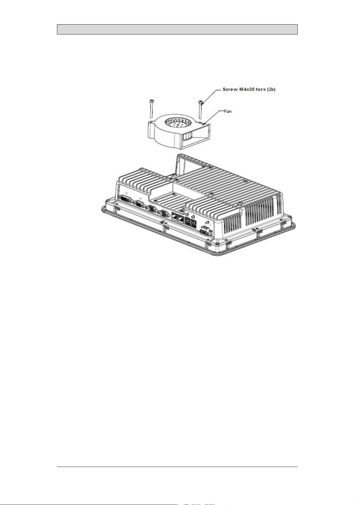
4.
Remove the fan by removing the two M4x35 Torx screws.
Hardware Replacement
5.
Reassemble with new fan and filter in reverse order. Use a maximum torque of
0.4 Nm when fasteningthe fan screws.
BeijerElectronics, MAEN084D
11
Page 12

Hardware Replacement
3.2 Replacingthe2.5”SATAMass Storage
The following is needed:
• A new 2.5” SATA mass storage
• A TX10 Torx screwdriver
Note:
MakesuretouseadequateESDprotection.
Followthe steps below to replace the 2.5” SATAmass storage:
1.
Poweroff the operator panel.
2.
Remove the frontframe assembly by removing the eight M3x8 Torx screws
on the back c over assembly.
Caution:
Duringdisassembly,itisimportanttotakecareofthecablebetweenthefrontandthe
rearpart. Ifyoudisconnecta cable,besurethattherightcablewillbeinthe right
positionwhenassembling.
Note:
Theexchangeofelectroniccomponentsis onlyforexperiencedprofessionals.
Incorrecthandlingofelectronic componentsorcablespluggedinwrong,canleadto
thedestruction ofthedevice.
3.
Remove the four M3x4 Torx screws on the two hard drive brackets. Remove
thetwoharddrivebrackets.
4.
Remove the two M3x6 Torx screws that are securing the brackets to the CPU
board.
BeijerElectronics, MAEN084D
12
Page 13

Hardware Replacement
5.
Remove the hard diskdrive fromthe harddrive connection on theCPU
board.
6.
Reassemble with the new hard disk drive in reverse order.
1. 2.5” SATAmass storage
2. CompactFlash slot
3. CFast slot
BeijerElectronics, MAEN084D
13
Page 14

Hardware Replacement
3.3 ReplacingaCompactFlashorCFast MemoryCard
The following is needed:
• A new CompactFlash or CFast memory card.
• A TX10 Torx screwdriver
Note:
MakesuretouseadequateESDprotection.
Follow the steps below to replace a memory card:
1.
Poweroff the operator panel.
2.
Followthe instructionsin chapter Replacing the 2.5” SATA Mass Storage to
removethefrontframeassembly.
3.
Install the new memorycard in its intended slot illustrated in figure below.
1. 2.5” SATA mass storage
2. CompactFlash slot
3. CFast slot
4.
Reassemble in reverse order.
BeijerElectronics, MAEN084D
14
Page 15

Hardware Replacement
3.4 ReplacingtheBattery
The following is needed:
• A new BR 2032 (or CR 2032) battery.
• A Torx screwdriver
Note:
MakesuretouseadequateESDprotection.
Followthe steps below to replace the battery:
1.
Poweroff the operator panel.
2.
Followthe instructionsin chapter Replacing the Fan and Filter to removethe
fan and access the battery.
3.
Replace the battery.
4.
Reassemble in reverse order.
BeijerElectronics, MAEN084D
15
Page 16

Technical Data
4TechnicalData
Parameter iXT21C
Frontpanel,W×H×D 556×347×87mm
Cutoutdimensions,
W×H
Mountingdepth 79mm(179mmincludingclearance)
Standalonemounting VESA100×100
Frontpanelseal IP65
Rear panel seal IP 20
Touch screen
material
Touch screen
operations
Reverse side
material
Framematerial Powder-coatedaluminum
Weight 8.1 kg
Serialportfor
COM1RS232and
COM2RS422/RS485
Serialportfor
COM3RS232and
COM4RS422/RS485
Ethernet 2×10/100/1000Base-T(shieldedRJ45)
USB 4×USBHost 2.0,maxoutputcurrent 500mA
Processor Intel®Celeron®B810E(2×1 .6 GHz),2MBL2C ache,
Externalstorage
media
MemoryRAM 2GB*/4GB* DDR-3SO-DIMM1333MHz
LED 1×multi-color
Real timeclock Yes(onchip)
Battery LithiumbatterytypeBR2032(orCR2032),e xchangeable
Powerconsumption
atratedvoltage
Fuse 10A
539×331mm
Note: MaximumscrewlengthforVESAmounting is5.5mm.
Usageoflongerscrewsmayleadto damage.
Polyesteronglass,resistive.
Overlay: AutotexF157 orF207
1millionfingertouch operations
Powder-coatedaluminum
9-pinD-subcontactwithRS232 RTS/CTS,chassis-mounted
femalewithstandard lockingscrews4-40UNC
Note: RS422Interface isnotavailableyet.
9-pinD-subcontactwithRS232 RTS/CTS,chassis-mounted
femalewithstandard lockingscrews4-40UNC
Note: RS422Interface isnotavailableyet.
Intel®QM67Chipset
Optional: Intel®Core™i32310E(2×2.1GHz)(Hyperthreading),3MBL2Cache, QM67Chipset
Optional: Intel®Core™i72715QE(4×2.1GHz)(Turbo
2.0,Hyperthreading),6MBL2Cache,QM67Chipset
*forexactconfigurationpleaseseep rice list
viaUSB
*dependingonProcessorModule
125W
(1)
.
BeijerElectronics, MAEN084D
16
Page 17

Parameter iXT21C
Powersupply DCinputrange: 18-32VDC (140W)ATXstandard
CE:Thepowersupplymustconformwiththerequirements
accordingtoIEC60950andIEC61558-2-4.
ULandcUL:Thepower supplymustconformwiththe
requirementsforclassIIpowersupplies.
Display TFT-LCDwithLEDbacklight. 1920×1080pixels,
16.7millioncolors
VGA 1×VGA:resolutionmax. 2048× 1536@75Hz
DVI 1×DVI-DsingleLink: Resolutionmax. 1600×1200or
1920×1200(withreducedblanking)
Activeareaof
display,W ×H
Operating
temperature
Storagetemperature -20°C–+70°C
Relativehumidity 5-85%non-condensed
Approvalsand
certifications
476.64×268.11mm
0°C–+50°C
Informationisavailableonthewebsite
www.beijerelectronics.com
Technical Data
(1)
SeesectionChemicalResistanceformore information.
BeijerElectronics, MAEN084D
17
Page 18

Chemical Resistance
5 ChemicalResistance
5.1 MetalCasing
The frame and casing material is powder-coated aluminum. This powder paint
withstands exposure to the following chemicals without visible change:
Aceticacid10% Phosphoricacid4%
Citricacid10% Phosphoricacid10%
Diesel Seawater
Distilledwater Sodiumchloride2%
Edibleoil Sodiumchloride20%
Fueloil Sulphuricacid20%
Hydrogenperoxide3% Tap water
The powder paint shows limited resistance to the f
ollowing chemicals at room
temperature:
Butanol Nitricacid3%
Hydrochloricacid5% Nitricacid10%
Isopropylalcohol Phosphoricacid43%
Na-hypochlorite10% Turpentine
Note:
Ifexposuretoanyoftheabove chemicalsis demanded,itisrecommended tofirsttest
thechemicalinahiddenspotof themetalcasing.
Thepowderpaintshowslittleornoresistancetothefollowingchemicalsatroom
temperature:
Aceticacid,conc. Methyl-ethylketone Toluene
Acetone Nitricacid30% Trichlorethylene
Ammonia5% Phenol Xylene
Ammonia,conc. Sodiumhydroxide5% 97octaneunleadedpetrol
Ethylacetate Sodiumhydroxide30% 98octaneleadedpetrol
BeijerElectronics, MAEN084D
18
Page 19

Chemical Resistance
5.2 TouchScreenandOverlay
5.2.1 AutotexF157/207
Autotex F157 or F207 covers the overlay surrounding the touch screen.
SolventResistance
Autotex F157/F207 withstands exposure of more than 24 hours duration under
DIN42115Part2tothefollowingchemicalswithoutvisiblechange:
(1)
(1)
Phosphoricacid(<30%)
SBP60/95
(1)
Wisk
(1)
-
Acetonitrile DieselDowney/Lenor
Ajax/Viminsolution Ethanol Potassiumferricyanide
Alkalicarbonate
solution
Ammonia(<40%)
Aceticacid(<50%) Gumption
Arielpowderin
solution
Bleach
Castoroil Methanol Trichloroaceticacid(<50%)
Causticsoda(<40%)
Cuttingoil Paraffinoil Windex
Cyclohexanol Persilpowderin
Diacetonealcohol Petroleumspirit
(1)
(1)
(1)
(1)
(1)
Extremelyfaint glossingofthe texturewasnoted.
Glycerine Potassiumhydroxide(<30%)
Glycol PureTurpentine
(1)
Hydrochloricacid(<36%) Sulfuricacid(<10%)
Linseedoil Tomatoketchup
(1)
Nitricacid(<10%) WhiteSpirit
solution
(1)
Autotex withstands DIN 42 115 Part 2 exposure of up to 1 hour duration to glacial
acetic acid without visible change.
Autotex is n
chemicals
ot resistant to high pressure steam at over 100 °C or the following
:
Concentratedmineralacids Benzylalcohol
Concentratedcausticsolution Methylenechloride
BeijerElectronics, MAEN084D
19
Page 20

Chemical Resistance
5.2.2 TouchScreenSurface
The touch screen surface on the operator panel withstands exposure tothe
following solvents without visible change:
Solvents Time
Acetone 10minutes
Isopropanol 10minutes
Toluene 5 hours
5.2.3 Autotex
It is recommended to use the Autoflex EBA 180Ltouch display protection film,
that can be ordered from Beijer Electronics.
SolventResistance
Autoflex EBA 180L withstandsexposure tothesamechemicalsasAutotexF157or
F207 according to section Autotex F157/207.
OutdoorUse
In common with all polyester based films, AutoflexEBA 180L is not suitable for
use in conditions of long-term exposure to direct sunlight.
BeijerElectronics, MAEN084D
20
Page 21

Operator PanelDrawings
6 OperatorPanelDrawings
6.1 Connectors
12345678 9
Pos. Connector Description
1DVI Externalmonitor
2VGA Externalmonitor
3 COM3/4 CommunicationPorts
4 COM1/2 CommunicationPorts
5 LANPortB 1×10/100/1000Base-T(shieldedRJ-45);Intel82574
6 LANPortA 1×10/100/1000Base-T(shieldedRJ-45);Intel82559
7 USB 2 ×USBHost2.0,maxoutputcurrent500 mA
8 USB 2 ×USBHost2.0,maxoutputcurrent500 mA
9 Powersupply DCinputrange: 18-32VDC(140W)ATXstandard
6.2 CommunicationPorts
Pin
1-
2 RS232RxD - RS232RxD 3 R S232 TxD - RS232TxD 4 - RS422Rx+ - RS422Rx+
5 GND GND GND GND
6-
7 RS232RTS - - RS422RTS+
8 RS232CTS - - RS422 RTS9 - RS422Rx- - RS422Rx-
Note: RS422Interfaceisnotavailableyet.
Serialport,9-pinfemale Serial port, 9-pinfemale
COM1 COM2 COM3 COM4
RS422Tx+
RS485Tx+/Rx+
RS422Tx-
RS485Tx-/Rx-
-
-
RS422Tx+
RS485Tx+/Rx+
RS422Tx-
RS485Tx-/Rx-
BeijerElectronics, MAEN084D
21
Page 22

Operator PanelDrawings
Note:
Inordertoutilizetwocommunicationportsonthesamephysicalport,theY-splitcable
CAB109mustbeused.
DrawingforexternalcableCAB109(drawing# Z7100-029E)isavailableonthewebsite:
www.beijerelectronics.com
BeijerElectronics, MAEN084D
22
Page 23

6.3 iXT21COutline
556
Operator PanelDrawings
347
max. 8 mm
8
79
99
99
537
329
BeijerElectronics, MAEN084D
23
Page 24

Operator PanelDrawings
Note:
AStepCADfileisavailableonthewebsite www.beijerelectronics.com
BeijerElectronics, MAEN084D
24
Page 25

Additional Installation Tips
7 AdditionalInstallationTips
When experiencingcommunication problems in for example noisy environments
or when operating closeto temperature limits, the following recommendations
are to be noticed.
7.1 GroundingtheOperatorPanel
Door
Operator panel
1
Ferrite core
6
3
2
5
4
Mounting plate in the cabinet
Power supply
24 V DC
5350
The operator panel’s mounting clamps do not provide a secure ground ing
connection between the panel and the device cabinet, see 1 in drawing above.
1.
Connect a 2.5 mm
2
wire between the operator panel’s quick-connect plinth
and the panel’s chassis, see 2 in drawing above.
2.
Connect a 6 mm
2
or 4 mm2wire or grounding braid between the operator
panel’s chassis and the closest grounding point on the door,see 3 in drawing
above.
3.
Connect a strong but short grounding braid between the door and the device
cabinet,see 4 in drawing above.
4.
Twist the cables onto the 24 V
cross-section of the cable
DC feed, see 5 in drawing above. Minimum
is 2.5 mm
2
.
2 turns around the ferrite core provide 4 times the suppression of 1 turn.
3 turns around the ferrite
core provide 9 times the suppression of 1 turn.
A ferrite core suppresses disturbancesto the 24 V feed, see 6 in drawing above.
BeijerElectronics, MAEN084D
25
Page 26

Additional Installation Tips
Note:
Thegroundingwiresshouldbeshort andtheconductorshouldhave alargearea.
Along,thingroundingwirehas averyhighimpedance(resistance)athighfrequencies
andwillnotguidedisturbancestothe ground.
Multi-wireconductorsarebetterthansinglewireconductorswiththesamearea.
Abraidedconductorwirewiththe samearea isevenbetter. The bestisashort,thick
groundingbraid.
7.2 EthernetConnectioninthe OperatorPanel
Industrial Ethernet
RJ45
RJ45
1
RJ45
RJ45
Operator panel
Shielded
0.1 μF
250 V
RJ45
3
4
1-1
2-2
3-3
8-8
Short and
unshielded
5
Operator panel
RJ45
Operator panel
RJ45
Operator panel
RJ45
2
In some industrial units for Ethernet, the RJ45 contact’sshield is connected to the
chassis via a capacitor, see 1 in drawing above.
The operator panel’s Ethernet shield is directly connected to the chassis, see 2 in
drawing above.
1.
Check whether the other Ethernet unit has its shielddirectly grounded or
grounded via a capacitor.
Note:
Inmanycases,connectingtheshieldedEthernet cablingtothechassisatbothends is
inappropriate. Humorgroundingloopscan occur. Unshielded cablingmayevenresult
infewercommunicationerrors.
BeijerElectronics, MAEN084D
26
Page 27

Additional Installation Tips
A good solution may be to use a shielded Ethernet cable, butto connect the shield
at one end only.
One option is to break the shield, see 3 in drawing above.
A more elegant method is to expand the shieldedEthernet cabling with a piece of
unshielded Ethernet cable, see 4 in drawing above.
The shield can be grounded via an external 0.1 μF/250 V plastic capacitor, see 5 in
drawing above. Thiswill connect the HF transients to ground.
BeijerElectronics, MAEN084D
27
Page 28

Additional Installation Tips
7.3 ToAchieveBetterEMCProtection
• Initially, use the original cabling from Beijer Electronics primarily.
• Useshielded cables for RS232 communication.
• Usetwisted pair and s hielded cabling for RS422 and RS485.
• Usethe cablingintended for the bus type; Ethernet, Profibus, CC-Link,
CAN, Device Net etc.
• Install and connect according to applicable specifications for the relevant bus
standard.
• Useshielded cabling for Ethernet, preferably with foil and a braided shield.
• D-sub covers should be shielded, and the shield should be connected to the
cover 360° where the cable enters.
• Connect the shield at both ends.
Shielded cable
0.1 μF/250 V
Ground plane 1 Ground plane 2
Ground plate Ground plate in another building
Not same potential
With longer distances, there is a risk that the ground potential may
In that case, the shield should only be connected at one end. A good
is to connect the other end of the shield to the ground via a
capacitor. Both ends are then connected to the ground in
connected to the ground at one end in terms of LF, thus av
0.1 μF/250 V plastic
terms of HF, but only
oiding the 50/60 Hz
be different.
alternative
grounding loops.
Metal cabinet Metal cabinet
Terminal or connector Terminal or connector
Cable clamp
in steel
Short distance
EMC cable gland
Shielded cable
1.
Usean EMC cable gland or regular plasticcable gland, remove the outer jacket
Shielded cable
Plastic cable gland
andconnecttheshieldtotheinstallation plate with a 360° metal cable clamp.
2.
Place the 24 V DC and communications cabling in one cable trunk/cableduct
and 230/380 V AC in another. If the cables need to be crossed, cross them at
90° only. Avoid combiningthe cabling for stronger 24 V DC outputs with
the communication cabling.
Ferritecores that are snapped onto the shielded cabling may remove minor
disturbances. Large ferrite pieces that are snapped onto unshielded cabling and
where the wires go 2-4 times around the cores are approximately 5-25 times more
efficient.
BeijerElectronics, MAEN084D
28
Page 29

Additional Installation Tips
7.4 AmbientTemperature
The maximum ambient temperature for the operator panel is provided in the
specifications. The ambient temperature refers to the temperature in the device
cabinet which cools t he operator panel’s electronics.
To p
50 °C inside
Operator
panel
30 °C outside
Middle
45 °C inside
Bottom
40 °C inside
Powe r
Powe r
Powe r
Axial fan
120 x 120 mm
Airflow
Inmostcases,theambienttemperaturefortheoperatorpanelissignificantly
higher than the device cabinet’s ambient temperature.
If the cabinet is tall and there are a number of heat-generatingdevices, the
temperature at the top of t he cabinet will be considerably higher than the
theoretical temperature increase that would be expected. All electronics are
sensitivetoheat. Thelifespanofanelectrolyticcapacitoriscutinhalfwithan
8-10 °C increase in temperature. A 15-20 °C temperatureincrease results in a
quarter of the lifespan etc.
Rittal has a good program for estimating the anticipated average temperature in
the cabinet as well as a large program for controlling the temperature in the device
cabinet.
2
An enamel-coated steel cabinet has a radiant heat value of 5.5 W/m
and degrees
C.
Installing a fan inside the cabinet will even out the temperature, while moving air
provides considerably better cooling than still air.
Install the fan so that it sits in the cooler area and blows cold air againstthe operator
panel. If the fan is mounted at the top and sucks warm air upwards, the fan’s
ambient temperaturewill be higher,resulting in a shorterlifespan.
The operator panel’s loss effect = supply voltage x current. Virtually no power goes
to external users and no loss effects due to inputs.
BeijerElectronics, MAEN084D
29
Page 30

7.5 Safety
Most of the operator panels are fed with 24 V DC.
Power supply
1
2
3
230 V AC to 24 V DC
Power supply
230 V AC to 24 V DC
Power supply
230 V AC to 24 V DC
230 V AC
+24 V
0 V
4
+24 V
0 V
4
Distance?
+24 V
0 V
4
Operator panel
Operator panel
Operator panel
Small controller with expansion unit
COM1
COM100
Ch0
Ch1
Ch100
Ch101
5355
Additional Installation Tips
If a power supply that meets safety standards is used and only feeds the operator
panel, there is no problem. See 1 in drawing above.
However, if a 24 V unit that also feeds other units is used, there is reason to be
cautious, see 2 indrawing above. Theoperator panel does not have insulation
that meets safety requirements in the event of a potential short circuit between
230 V AC and 24 V DC. It is assumed that the 24 V feed is secure, for example,
SELV according to EN 60950 (protection against electric shock) and UL 950.
Example:
Hereisanexamplethatexplains whyasecure24V DCfeedcanberuinedbymixing
24Vrelaycontactswith230VACrelay contactsinasmallercontroller. Check thatthe
clearancesandcreepagedistancesbetween24VDCand 230VACfulfillEN60950or
UL950. Ifnot,inputa separate24Vunitinto theoperatorpanel.
If there is a substa
230 V AC, it is OK t
ntial distance between the relay contacts for 24 V DC and
ousethesame24Vdevicesforallfeeds. See3indrawing
above.
Connect 0 V on the 24 V feed to the ground, see 4 in drawing above. This offers
three advantages:
• Safety is incr
connection o
• Tr a n s i e n t s
• No risk tha
is not unu
eased. The24Vfeedwillnotbeliveintheeventofafaulty
rshortcircuitbetween0V(24V)and230Vphase.
on the 24 V feed are connected to the ground.
t the 24 V feed is at a high level in relationshipto the ground. This
sual since there is high static electricity.
BeijerElectronics, MAEN084D
30
Page 31

Additional Installation Tips
7.6 CableandBusTerminationRS485
• If maximum transfer distanceand maximum transfer speed is needed,
shielded and twisted pair cable should be used. The mutual capacitance
may not exceed 52.5 pF/m, and the cable area should be at least 0.25 mm
(AWG 24).
• 0 V, the reference voltage for communication should be included in
the cabling. With two-way communication use two pairs; one pair for
communication and one pair for 0 V.
• The shield must be grounded at one end. The other end is usually grounded,
but with longer distancesor when there is a difference in the ground potential,
theshieldshouldbeconnectedtothegroundvia0.1μF/250Vplastic
capacitor to preventground current in the braided shield. A number of
manufacturers recommend that the shield be grounded at each node. Various
manufacturers have different systems for bus termination.
Depending on the recipients’ design, the bus wires may be on the same level or
require pull-up or pull-down to ensure that no faulty signals are detected when the
bus is in resting mode (all transmitters are disconnected).
2
BeijerElectronics, MAEN084D
31
Page 32

Additional Installation Tips
7.7 BootPriority
The boot priority is the order in which the hardware storage devices are read.
PressingF7 during boot will display a drop down menu with all availablebootable
devices.
A change of the boot priority is only temporary. Onnext startup the boot priority
will be restored back to the factory setting.
7.8 EnteringBIOS
Caution:
Unlessyouareanexpertcomputer user,donotchangetheBIOSsettingsforthis
program. Certainchangescancauseyouroperatorpaneltoworkincorrectly.
Note:
BeforeusingBIOSsetup,itis recommendedtowritedownthesetupinformationfor
futurereference.
Note:
Itisrecommendedtoturnonandshutdowntheoperatorpanelatleastoncebefore
installinganycomponents/cardsorbeforeconnectingt he paneltoexternaldevices,
likeforexampleserial devices.
1.
Connect a USB Keyboard.
2.
Connect power supply and turn on the operator panel.
3.
While booting, press the F2 key immediately after the keyboard is initialized.
The initialization is indicated by the keyboard LED's.
If F2 is pressed before the keyboard is initialized, this keystroke w ill be lost.
If you waited too long and the operating system logo appears, continue to
wait until the operating system desktop is appearing. Then,shut down the
operator panel and tryagain.
Note:
ThekeyusedtoentertheBIOS setupcandifferdependingonmodeland CPUBoard.
ThecommonlyusedkeysareESC,DEL,F1andF2. Formoreinformation,refertothe
BIOSmanual.
The system s
• Change the system configuration (new installed hardware).
• Setup boot devices and sequences.
• Setuporchangeuseroptions,forexamplepasswords.
• Read the installed memory and environmental parameters, for example CPU
etup allows to:
heat.
Formore information, refer to the BIOS manual.
BeijerElectronics, MAEN084D
32
Page 33

7.9 ResetSwitch
A reset switch is located under the fan lid.
Additional Installation Tips
Followthe instructionsin chapter Replacing the Fan and Filter on how to remove
the fan lid to access the reset switch.
BeijerElectronics, MAEN084D
33
Page 34

Headoffice
BeijerElectronicsAB
Box426
20124Malmö,Sweden
www.beijerelectronics.com/+4640358600
 Loading...