

Page 1

T15BR
Installation Manual
MAEN165,2014-04
English
Page 2

Foreword
Installationmanual forT15BR
Foreword
All operator panels are developed to satisfy the demands of human-machine
communication. Built-in functions such as displaying and controlling text,
dynamic indication, time channels, alarm and recipe handling are included.
The operator panel works primarily in an object-oriented way,making it easy to
understand and use. Configuration is carried out on a PC using the iX Developer.
Theprojectcanthenbetransferredandstoredintheoperatorpanelitself.
Various types of automation equipment such as PLCs, servos or drives can be
connected to the operator panels. In this manual, the term “the controller” refers
to the connected equipment.
This manual explains how to install the operatorpanel. Please refer to the
iX Developer reference manual for furtherinformation.
Order no: MAEN165
Copyright © 2014-04 Beijer Electronics AB. Allrights reserved.
The information in this document is subject to changewithoutnoticeandisprovidedasavailableatthe
time of printing. Beijer Electronics AB, including all its group companies, reserves the right to change any
information without updating this publicatio n. Beijer Electronics AB, including all its group companies,
assumesnoresponsibilityforanyerrorsthatmayappearinthisdocument. Read theentireinstallation
manual prior to installing and using this equipment. Only qualified personnel may install, operate or repair
this equipment. BeijerElectronicsAB,including all its group companies, are not responsible for modified,
altered or renovatedequipment. Because the equipment has a wide range of applications, users must acquire
the appropriate knowledge to use the equipment prope rly intheir specific applications. Persons responsible
for the application and the equipment mustthemselvesensurethateach application is in compliance with
all relevant requirements,standardsandlegislationinrespecttoconfigurationandsafety. Onlypartsand
accessoriesmanufacturedaccording to specifications set by Beijer Electronics AB, including all its group
companies, may be used.
BEIJER ELECTRONICS AB, INCLUDING ALL ITS GROUP
COMPANIES,SHALL NOT BE LIABLE TOANYONE FOR ANY
DIRECT, INDIRECT, SPECIAL, INCIDENTALOR CONSEQUENTIAL
DAMAGES RESULTINGFROMTHE INSTALLATION,USE OR
REPAIROF THIS EQUIPMENT, WHETHER ARISING IN TORT,
CONTRACT, OR OTHERWISE. BUYER'S SOLE REMEDY SHALL
BE THE REPAIR,REPLACEMENT, OR REFUND OF PURCHASE
PRICE, AND THE CHOICE OF THE APPLICABLE REMEDY SHALL
BE AT THE SOLE DISCRETION OF BEIJER ELECTRONICSAB,
INCLUDING ALL ITSGROUP COMPANIES.
BeijerElectronics, MAEN165
Page 3

Contents
Contents
1 Safety Precautions ....................................................... 4
1.1 General ...........................................................
1.2 UL and cUL Installation .........................................
1.3 High Potential Testing .... .......................................
1.4 DuringInstallation ..............................................
1.5 During Use .......................................................
1.6 Service and Maintenance ........................................
1.7 Dismantling and Scrapping .....................................
1.8 Appearance of Air in Touch Screen .............................
2 Installation ............................................................... 8
2.1 SpaceRequirements .............................................
2.2 InstallationProcess ..............................................
2.2.1 Connections to the Controller ......... .........................
2.2.2 HazardousLocationInstallation .... ............................
2.2.3 Other ConnectionsandPeripherals ............................ .
3 Technical Data ........................................................... 12
4 Chemical Resistance .................................................... 14
4.1 MetalCasing .....................................................
4.2 Touch Screen and Overlay .......................................
4.2.1 AutoflexEB ............................................ ..........
4.2.2 TouchScreen Surface ................... .........................
4.2.3 TouchscreenProtective Film ................................ ....
4.3 Terminal to Panel Gasket ........................................
5 OperatorPanel Drawings .............................................. 18
5.1 Connectors .......................................................
5.2 CommunicationPorts ...........................................
5.3 T15BR Outline ..................................................
6 Additional Installation Tips ............................................ 20
6.1 Grounding the Operator Panel .................................
6.2 Ethernet Connection in theOperatorPanel ...................
6.3 To Achieve Better EMC Protection .............................
6.4 Ambient Temperature ...........................................
6.5 Safety .............................................................
6.6 Galvanic Isolation ................................................
6.7 Cable and Bus Termination RS485 .............................
6.8 COM Port Common-ModeVoltage ...........................
10
11
11
14
15
15
16
16
17
18
18
19
20
21
23
24
25
26
27
27
4
4
6
6
6
6
7
7
8
9
BeijerElectronics, MAEN165
Page 4

Safety Precautions
1SafetyPrecautions
Both the installer and the owner and/or operator of the operator panel must read
and understand this installation manual.
1.1 General
• Read the safety precautionscarefully.
• Check the delivery for transportation damage. If damage is found, notify the
supplier as soon as possible.
• The supplier is not responsible for modified, altered or reconstructed
equipment.
• Use only parts and accessories manufactured according to specifications of
the supplier.
• Read the installation and operating instr u ctions carefully before installing,
using or repairing the operator panel.
• Neverallowfluids,metalfilingsorwiringdebristoenteranyopeningsinthe
operator panel. This may cause fire or electrical shock.
• Only qualified personnel may operate the operator panel.
• Storing the operator panel where the temperature is lower/higher than
recommended in this manualcan cause the LCD display liquid to
congeal/become isotopic.
• The LCD display liquid contains a powerful irritant. Incase of skin contact,
wash immediately with plenty of water. In case of eye contact, hold the eye
open,flushwithplentyofwaterandgetmedicalattention.
• Thefiguresinthismanualservesanillustrativepurpose. Becauseofthemany
variables associated with any particular installation, the supplier cannot
assume responsibility for actual use based on the figures.
• The supplier neither guaranteesthat the operator panel is suitable for your
particular application, nor assumes responsibility for your product design,
installation or operation.
• It is recommended to turn on and shut down the operator panel at least once
before installing any components/cards or before connecting the operator
panel to externaldevices, like for example serial devices.
• This operator panel is certified to operate in a Class I, Division 2, GroupA, B,
C and D hazardous environment. Theoperator panel must be installed and
operated as described in this document to meet this certification.
• Observe precautionsfor handling electrostatic discharge sensitive devices.
1.2 ULandcULInstallation
• All devices have to be supplied by a Class 2 power supply.
BeijerElectronics, MAEN165
4
Page 5
Safety Precautions
Warning:
Do not disconnect equipment unlesspower has been removed or thearea is
knownto be non-hazardous
AVANT DE DECONNECTER L’EQUIPEMENT, COUPERLE COURANT
OUS’ASSURER QUE L‘EMPLACEMENT ESTDESIGNE NON DANGEREUX.
Warning:
Batterymay explode if mistreated. Do not recharge, disassembleordispose
of in fire.
This product contains a BR2330A batterythat is not user replaceable.
LA BATTERIE P E UT EXPLOSER EN CAS DE MAUVAISEMANIPULATION.
NE LA RECHARGEZPAS, NELA DÉMONTEZ PAS ETNE LA JETEZ
PAS DANS LE FEU.
CEPRODUITCONTIENTUNEPILEBR2330AQUINEPEUTPASÊTRE
REMPLACÉE PAR L'UTILISATEUR.
• Use minimum 75°C copper conductors only.
• To make wiring connections to the power supply connector, follow the table
with cable and torquespecifications below:
TerminalBlockConnector WireSize TQLb.In.
PhoenixContactPart No. 1757022 14–20AWG
(2.08–0.52 mm
Warning:
Donotopenwhenanexplosiveatmosphere is
N'OUVREZPASSIUNE ATMOSPHÈRE EXPLOSIVE
Warning:
Explosionhazard! Donotdisconnectwhile circuit islive unless the area is
knownto be non hazardous.
RISQUE D'EXPLOSION ! NE DÉBRANCHEZ PAS LORSQUE LE CIRCUITEST
SOUS TENSION SAUF SILA ZONE EST CONNUEPOUR ÊTRE NON DANGEREUSE.
Caution:
This equipment is tes
minimumIP66.
CETÉQUIPEMENTEST
DANS UN BOÎTIER AV
Caution:
Temperaturecode T4 IEC/EN 60079-0 (2012) andIEC/EN60079-15 (2010).
CODES DE TEMPÉRATURET4IEC/EN60079-0(2012)ET IEC/EN 60079-15 (2010).
ted as a component and is tobe installed inside an enclosure rated
TESTÉENTANTQUECOMPOSANTETDOITÊTREINSTALLÉ
EC INDICE DE PROTECTION IP66 MINIMUM.
2
)
present.
EST PRÉSENTE.
5–7
BeijerElectronics, MAEN165
5
Page 6

Safety Precautions
1.3 HighPotentialTesting
Each terminal is high-pot (high potential) tested prior to shipment. After high-pot
testing surge arresting devices are installed into the terminal that will enhance
surge robustness. After placement, these deviceswillcausetheterminaltofail
high-pot testing.
Note:
If in-field high-pottesting is requiredcontact Beijer Ele ctronics.
1.4 DuringInstallation
• The operator panel is designed forstationary installation on a plane surface,
where the followingconditions are fulfilled:
– no high explosive risks
– no strong magnetic fields
– no direct sunlight
– no large, sudden temperature changes
• Install the operator panel according to the accompanying
installation
instructions.
• Ground the operator panel accordingto the accompanyin
ginstallation
instructions.
• Only qualified personnel may install the opera
• Separate the high voltage, signal and supply
• Make sure that the voltage and polarity of th
connecting the operator panel to the power
• Peripheralequipment must be appropriat
tor panel.
cables.
e power source is correctbefore
outlet.
efortheapplicationandlocation.
1.5 DuringUse
• Keep the operator panel clean.
• Emergency stop and other safety functions may not be controlled from the
operator panel.
• Do not use excessive force or sharp objects when operating the touchscreen.
1.6 ServiceandMaintenance
• Only qualified personnel should carryout repairs.
• The agreed warranty applies.
• Before carryin g out any cleaning or maintenance operations, disconnect the
equipment from the electrical supply.
• Clean the display and surrounding front cover with a soft cloth and mild
detergent.
• The batterymust be replaced by an authorized Beijer Electronics service
center.
BeijerElectronics, MAEN165
6
Page 7

Safety Precautions
1.7 DismantlingandScrapping
• The operator panel or parts thereofshall be recycled according to local
regulations.
• The following components contain substancesthat might be hazardous
to health and the environment: lithium battery,electrolytic capacitor and
display.
1.8 AppearanceofAirinTouchScreen
The layer structure of the touch screen contains air and in rare cases appearance of
bubbles can arise. This is purely cosmetic and does not affect any functionality
of the operator panel. The appearance can occur under certain environmental
conditions such as temperature, humidity,and atmospheric pressure.
BeijerElectronics, MAEN165
7
Page 8
2Installation
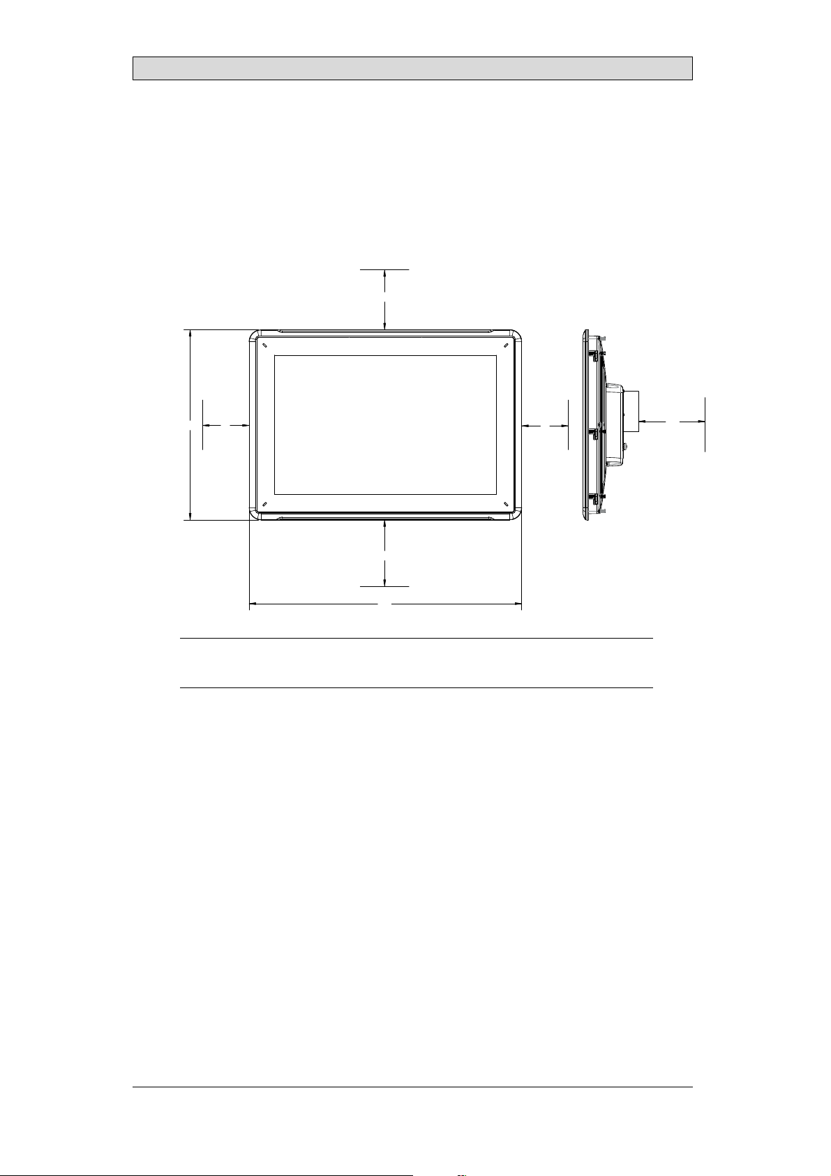
2.1 SpaceRequirements
• Maximum installation plate thickness: 8 mm
• Space requirements in millimeters when installing the operator panel:
100
Installation
286
50
100
410
Note:
The dimensions on thedrawing are not proportional.
50
100
BeijerElectronics, MAEN165
8
Page 9
Installation
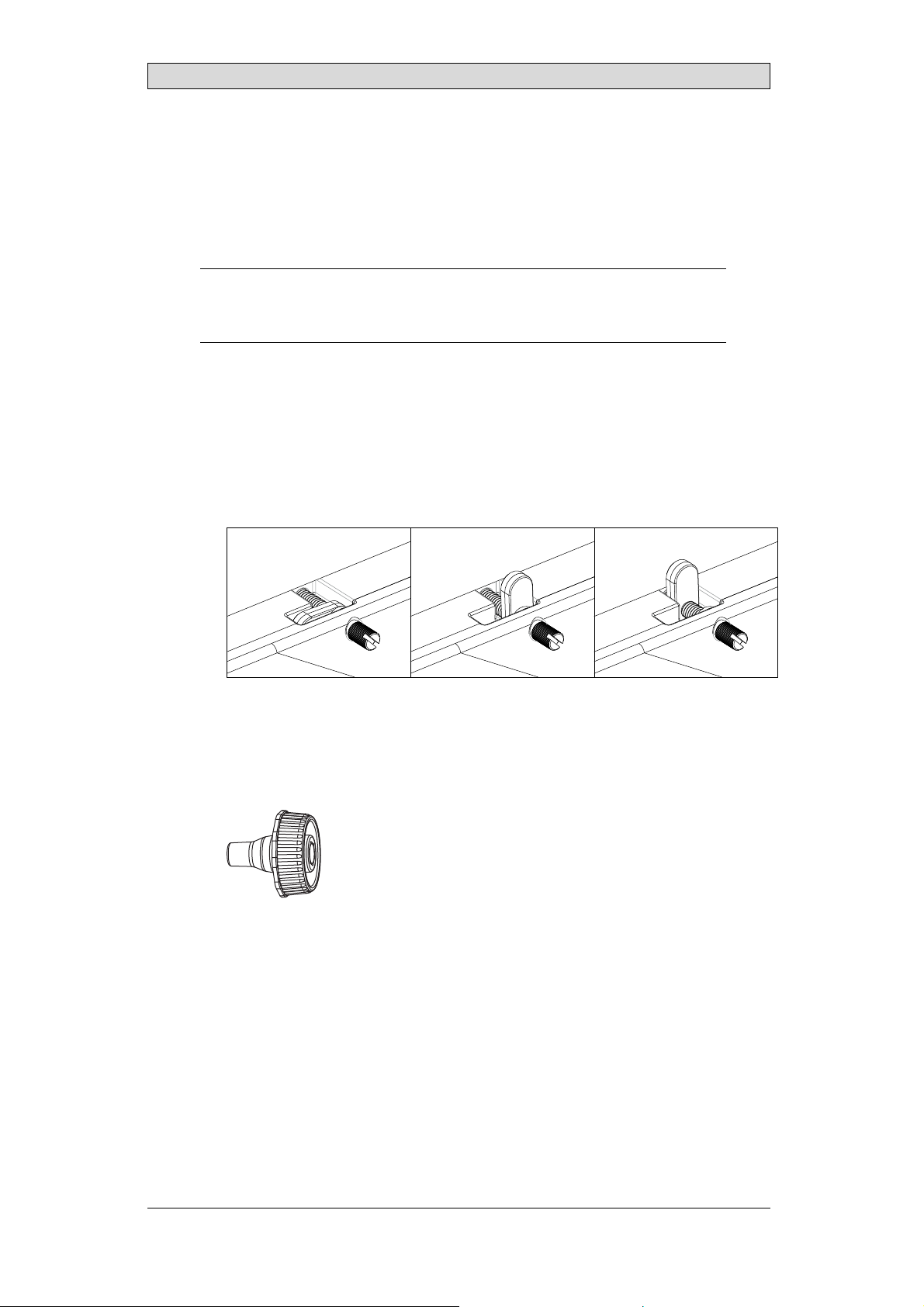
2.2 InstallationProcess
A Thumb Screw Installation Tool (provided) or a slotted screwdriveris required
for installation.
1.
Unpackand check the delivery. If damage is found,notify the supplier.
Note:
Place the operator panel ona stable surface during installation.
Dropping the operator panel orletting it fall may causedamage.
2.
To cut a correct opening for the operator panel, use the cut out dimensions
in the outline drawing. A separate cut out drawing is available for download
from the Beijer Electronics web site. For more information, see sections
Operator Panel Drawings and Technical Data.
3.
Secure the operator panel in position by screwing the slotted thumb screw
clockwise, allowing the built-in brackettoflipoutandtightenagainstthe
cabinet. Tightenthe screws (12) to 0.7 Nm ±0.2 Nm.
4.
Formost applications, the providedThumb Screw Installation Tool will
provide adequate torque. Incases where the front panel seal (IP66, NEMA-4)
is critical, a torque wrench should be used to ensure all twelve screws are
torqued within the specification above.
Thumb Screw InstallationTool
BeijerElectronics, MAEN165
9
Page 10
Installation
5.
Connect the cables in the specified order, according to the drawing and steps
below.
Caution:
• The operator panel must be brought toambienttemperaturebefore it is started
up. Ifcondensationforms,ensurethat the operator panel isdry before connecting
it to the power outlet.
• Ensurethat the operator panel and thecontrollersystem have the same electrical
grounding(reference voltage level), otherwise errors incommunication may
occur.
• Ensure that the voltage and polarityofthe power source is correct.
• Separatehigh voltage cables from signal and supplycables.
• Shielded communication cables are recomm ended.
B
RS232/
RS422/
RS485
24V DC
C
D
A
Ethernet
– Use 14–20 AWG (2.08–0.52 mm
– Connect cable A.
– Connect cable B, using an M
grounding conductor (as
according to local elec
– Connect cable C.
– Connect cable D.
6.
Carefully remove the la
static electricity
that could damage the panel.
trical codes.
minated film over the operator panel display, to avoid
Power
Controller
24V DC
2
ireforthepowerconnections.
)w
5 steel screw with zinc plating and a
short as possible), that is sized correctly
2.2.1 ConnectionstotheController
Forinformation about the cables to be used when connecting the operator panel to
the controller, please refer to the help file for the driver in question.
BeijerElectronics, MAEN165
10
Page 11

2.2.2 HazardousLocationInstallation
Connect the desired cables and attach them to strain relief plate with cable ties
provided.
Installation
2.2.3 OtherConnectionsandPeripherals
Cables, peripheralequipment and accessories must be suitable for the application
and its environment. For further details or recommendations, please refer to the
supplier.
BeijerElectronics, MAEN165
11
Page 12
3TechnicalData
Parameter T15BR
Frontpanel,W×H×D 410×286×83mm
Cut out dimensions,
W×H
Mountingdepth 76 mm (176 mm includingclearance)
Front panel seal IP 66, NEMA-4
Rear panel seal IP 20
Touch screen
material
Touch screen
operations
Reverse side
material
Frame material Powder-coated aluminum
Weight 4.13 kg (+ 0.13 kgwithCAN Module, + 0.15 kg withATEX)
Serialportfor
COM1 RS232 and
COM2 RS422/RS485
Communication
module
Ethernet 1 x 10/100/1000 Base-T (shielded RJ45)
USB 3 × USB Host2.0,max output current 500mA
Processor Intel® Atom
Externalstorage
media
Flash memory
(application
memory)
MemoryRAM 1 GB (iX version), 2 GB (PPC version)
LED 1 × multi-color
Real time clock Yes (on chip)
Battery BR 2330A
Power consumption
at rated voltage 12 V
/24Vrespectively
Fuse 5.0 A Slow
Powersupply +12 V to +28 V DC(10to 32 V DC)
Display TFT-LCDwithLEDbacklight. 1280 ×800pixels,
394 ±1 mm × 270 ±1mm. Maximumcornerradius: 4 mm.
ForIP66/NEMA-4, panel must maintain a flatness<1mm
overalland<0.05mm/mmwithasurfaceroughness,
<1.6μm.
R
a
Polyesteronglass, resistive.
Overlay: AutoflexEB
5 million finger touchoperations
Powder-coated aluminum
9-pin D-sub contact with RS232RTS/CTS,chassis-mounted
female with standard locking screws 4-40 UNC
CAN
1 × 10/100 Base-T (shielded RJ45)
1×SDcard(optional)
4 GB (iX version), 16 GB(PPC version)
Standby
Typica l
Estimatedmaximum
CE: The power supply m ust conformwiththe requirements
accordingto IEC 60950 and IEC 61558-2-4.
16.7 million colors
(2)
: 11.2 W/ 12.5 W
(3)
: 27.6W/28.8W
(1)
.
(4)
: 31.2W/31.2W
Technical Data
BeijerElectronics, MAEN165
12
Page 13

Technical Data
Parameter T15BR
Activeareaof
display, W ×H
Operating
temperature
Storagetemperature -40 °C to +85 °C
Approvalsand
certifications
(1)
See section ChemicalResistancefor moreinformation.
(2)
Standby mode: Thebacklightisturned off, there are no cabledinterfacesandthe
CPU is below 5%. OptionalCANmoduleis present.
(3)
Typical m ode: The backlight is fully powered, there are nocabledinterfacesand an
application is running. OptionalCANmodule is present.
(4)
EstimatedMaximum mode: Allinterfacesarecabled, all USB ports areplugged with
mass-storage devices, the CPU isat 50% and audio isactive. OptionalCANmodule is
presentand active.
331.2× 207.0 mm
Minimumtemperature:
-30 °C
Maximum temperature:
70 °C; UL 65°C
Information is available on the web site
www.beijerelectronics.com
BeijerElectronics, MAEN165
13
Page 14

Chemical Resistance
4 ChemicalResistance
4.1 MetalCasing
The frame and casing material is powder-coated aluminum. This powder paint
withstands exposure to the following chemicals without visiblechange:
Acetic acid 10% Phosphoricacid4%
Citricacid 10% Phosphoricacid10%
Diesel Sea water
Distilled water Sodium chloride 2%
Edibleoil Sodiumchloride 20%
Fuel oil Sulphuric acid 20%
Hydrogen peroxide 3% Tap water
The powder paint shows limited resistance to the fol
lowing chemicals at room
temperature:
Butanol Nitric acid 3%
Hydrochloric acid 5% Nitric acid 10%
Isopropyl alcohol Phosphoricacid43%
Na-hypochlorite10%
Sodiumhypochlorite
Note:
If exposure toany of theabove chemicals isdemanded, itis recommended to first test
the chemical in a hidden spotofthe metal casing.
Turpentine
Thepowderpaintshowslittleornoresistancetothefollowingchemicalsatroom
temperature:
Acetic acid, conc. Methyl-ethylketone Toluene
Acetone Nitricacid30% Trichlorethylene
Ammonia5% Phenol Xylene
Ammonia,conc. Sodiumhydroxide5% 97 octane unleaded petrol
Ethyl acetate Sodium hydroxide 30% 98 octane leaded petrol
BeijerElectronics, MAEN165
14
Page 15

Chemical Resistance
4.2 TouchScreenandOverlay
4.2.1 AutoflexEB
Autoflex EB coversthe overlay surrounding the screen.
SolventResistance
Autoflex EB withstands exposure of more than 24 hours duration under
DIN42115Part2tothefollowingchemicalswithoutvisiblechange:
(1)
(1)
(1)
Phosphoricacid(<30%)
SBP 60/95
(1)
Wisk
-
(1)
(1)
Ajax / Vim in solution Downy /Lenor
Alkalicarbonate
solution
Ammonia (<40%)
Acetic acid (<50%) Glycol Pure Turpentine
Ariel powder in
solution
Bleach
Castoroil Linseed oil Tomato ketchup
Causticsoda (<40%)
Cutting oil Nitric acid (<10%) White Spirit
Cyclohexanol Paraffinoil Windex
Diacetone alcohol Persilpowder in solution
Diesel Petroleumspirit
(1)
(1)
(1)
(1)
(1)
Extremely faint glossing of the texture was noted.
Ethanol Potassiumferricyanide
Glycerine Potassiumhydroxide(<30%)
Gumption
Hydrochloricacid(<36%) Sulfuric acid (<10%)
(1)
Methanol Trichloroaceticacid(<50%)
Autoflex EB withstands DIN 42 115 Part 2 exposure of up to 1 hour duration to
glacialaceticacidwithoutvisiblechange.
Autoflex EB is not resistant to high pressure steam at over 100 °C or the following
chemicals:
Concentratedmineral acids Benzyl alcohol
Concentrated caustic solution Methylenechloride
Dimethylformamide Tetrahydrofuran
BeijerElectronics, MAEN165
15
Page 16

Chemical Resistance
4.2.2 TouchScreenSurface
The touch screen surface on the operator panel withstands exposure to the
following solvents without visible change:
Solvents Time
Acetone 10 minutes
Isopropanol 10 minutes
Toluene 5 h o u r s
4.2.3 TouchscreenProtectiveFilm
AutoflexEB
It is recommended to use the Autoflex EB touch display protection film, that can
be ordered from BeijerElectronics.
OutdoorUse
In common with all polyester based films, Autoflex EB is not s
uitable for use in
conditions of long-term exposure to direct sunlight.
Note:
The layer structure of the touchscreen contains air and inrarecases appearance of
bubbles can arise. Thisis purely cosmetic and does notaffect any functionality of the
panel. Theappearancecanoccur under certain environmental conditions such as
temperature,humidity, andatmospheric pressure.
BeijerElectronics, MAEN165
16
Page 17

Chemical Resistance
4.3 TerminaltoPanelGasket
The gasket is made of flame retardant silicone rubber. The sealing capability is
unaffected by the following chemicals:
Acetic acid 10% Nitric acid 1.5%
Ammonia 10% Phosphoricacid4%
Citricacid 10% Seawater
Distilled water Sodium chloride 2%
Edibleoil Sodiumchloride 20%
Hydrogen peroxide 3% Sodium hydroxide 30%
Isopropyl alcohol Tap water
The flame retardant silicone rubber shows limited resistance to the following
chemicals at room temperature:
Acetic acid, conc. Na-hypochlorite10%
Ammonia30% Nitricacid10%
Butanol Phosphoricacid10%
Ethyl acetate Phosphoricacid 20%
Hydrochloricacid37%, cold -
Note:
If exposure toany of theabove chemicals isdemanded, itis recommended to first test
the chemical in a hidden spotofthe gasket.
Theflameretar
chemicals at
Acetone Methyl-ethylketone Trichlorethylene
Ammonia,conc. Nitricacid30% Turpentine
Diesel Phenol Unleaded petrol
Fuel oil Sulphuricacid20% Xylene
Leaded petrol Toluene -
dant silicone rubber showslittle or no resistance to the following
room temperature:
BeijerElectronics, MAEN165
17
Page 18

Operator PanelDrawings
5 OperatorPanelDrawings
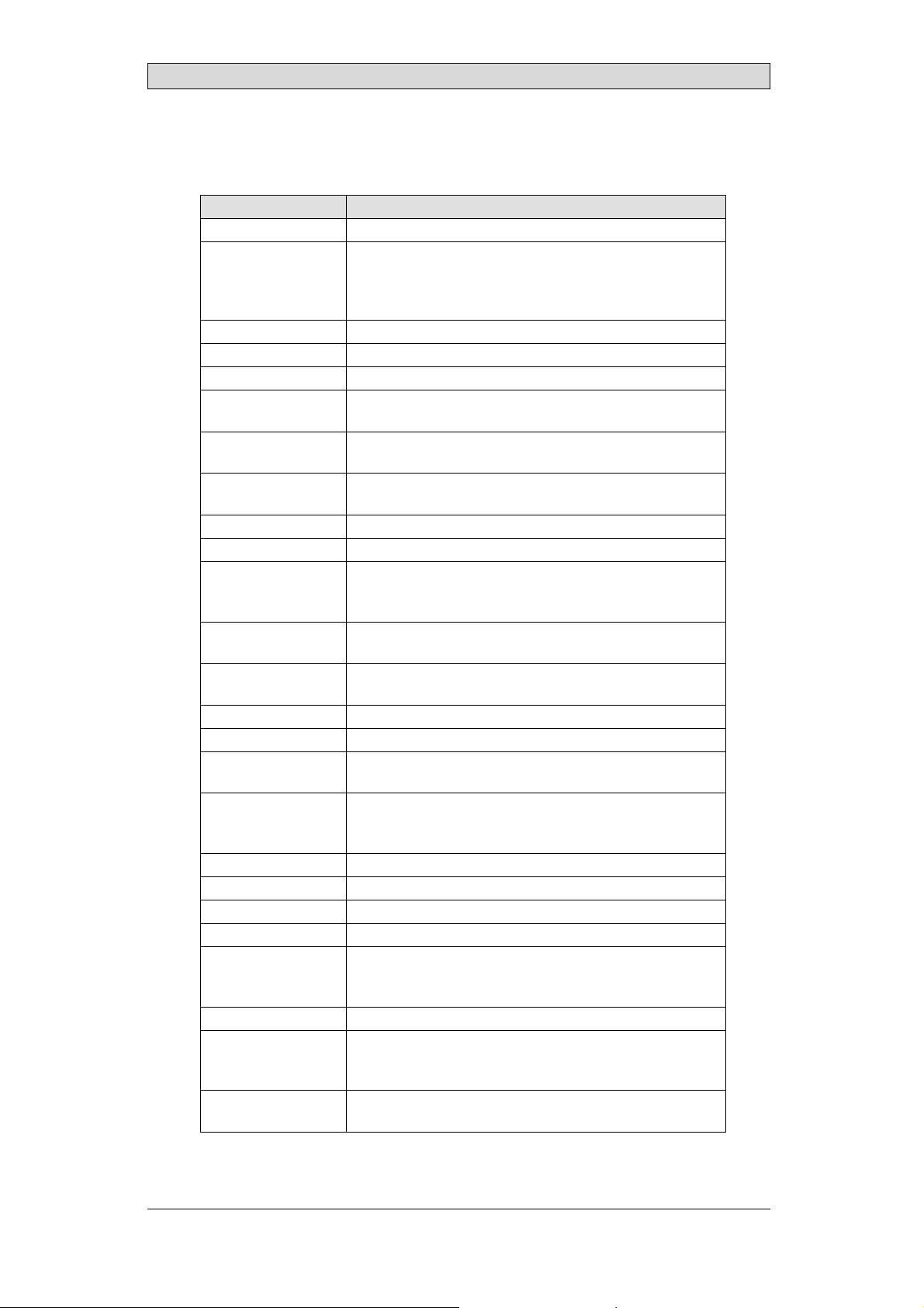
5.1 Connectors
Pos. Connector Description
1 Powersupply +12–+24VDC(10–32VDC)
2 COM1 RS232CommunicationPort
3 LANA 1 ×10/100 Base-T (shielded RJ45)
4 USB 2×USB Host 2.0, max output current500mA
5 Headphone HeadphoneConnector
6 LANB 1 x 10/100/1000Base-T(shieldedRJ45)
7 COM2 RS422/RS485 Communication Port
5.2 CommunicationPorts
Pin
COM1 COM2
1 - RS422 Tx+ RS485 Tx+/Rx+
2RS232RxD -
3RS232TxD -
4 - RS422 Rx+
5GND GND
6 - RS422Tx- RS485 Tx-/Rx-
7 RS232 RTS RS422RTS+
8 RS232CTS RS422 RTS-
9- RS422Rx-
Serialport,9-pin female
BeijerElectronics, MAEN165
18
Page 19

5.3 T15BROutline
Operator PanelDrawings
7
max. 8mm
76
410
9
286
268
A
E
9
9
392
9
B C
A. Connectors
B. SD memory cardslot
C. USB host
D. Expansion port
E. Optional CAN module (not shown)
CAN depth does not exceed heat sink.
E
D
BeijerElectronics, MAEN165
19
Page 20
Additional Installation Tips
6 AdditionalInstallationTips
When experiencingcommunication problems in for example noisy environments
or when operating clo se to temperature limits, the following recommendations
are to be noticed.
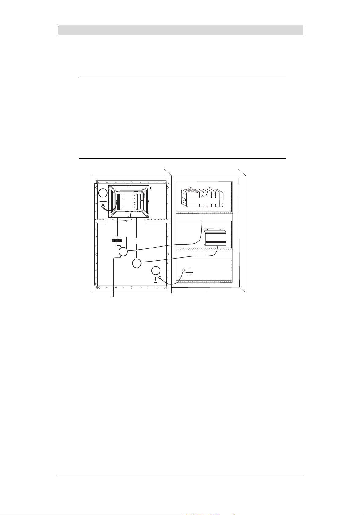
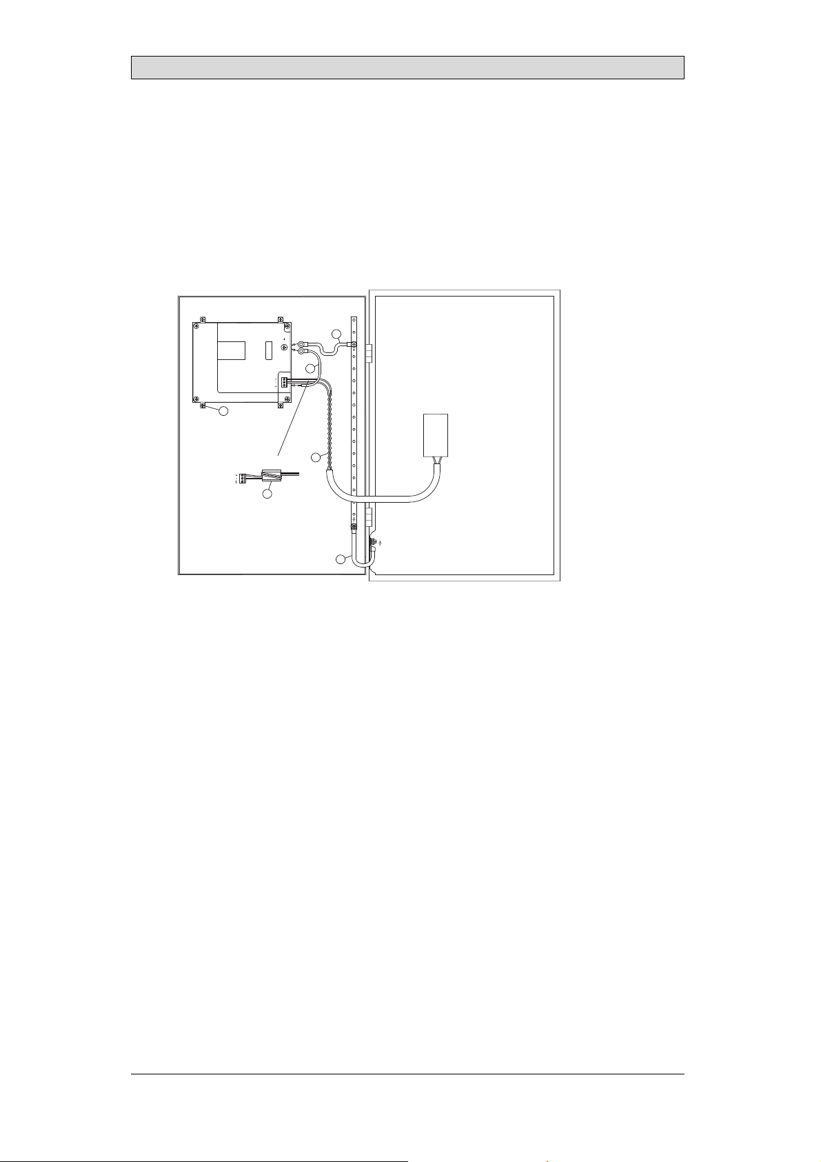
6.1 GroundingtheOperatorPanel
Door
Operator panel
1
Ferrite core
6
3
2
5
4
Mounting plate in the cabinet
Power supply
24 V DC
5350
The operator panel’s mounting clamps do not provide a secure grounding
connection between the panel and the device cabinet, see 1 in drawing above.
1.
Connect a wire that is sized correctly according to local electrical codes
between the operator panel’squick-connect plinth and the panel’s chassis, see
2indrawingabove.
2.
Connect a wire or grounding braid that is sized correctly according to local
electrical codes between the operator panel’s chassis and the closest grounding
point on the door, see 3 in drawing above.
3.
Connect a strong but short grounding braid between the door and the device
cabinet,see 4 in drawing above.
4.
Twist the cables onto the 24
V DC feed, see 5 in drawing above.
2 turns around the ferrite core provide 4 times the suppression of 1 turn.
3 turns around the ferrite
core provide 9 times the suppression of 1 turn.
A ferritecore suppresses disturbances to the 24 V feed, see 6 in drawing above.
BeijerElectronics, MAEN165
20
Page 21

Additional Installation Tips
Note:
The grounding wires should beshort and the conductor shouldhave a large area.
A long, thin grounding w ire hasa very high impedance (resistance) athighfrequencies
and will not guide disturbances tothe ground.
Multi-wireconductors are better thansinglewireconductorswiththesamearea.
A braided conductor wire with the samearea is even better. Thebestisa short, thick
grounding braid.
6.2 EthernetConnectioninthe OperatorPanel
Industrial Ethernet
RJ45
RJ45
1
RJ45
RJ45
Operator panel
Shielded
0.1 μF
250 V
RJ45
3
4
1-1
2-2
3-3
8-8
Short and
unshielded
5
Operator panel
RJ45
Operator panel
RJ45
Operator panel
RJ45
2
In some industrial units for Ethernet,the RJ45 contact’s shield is connected to the
chassis via a capacitor, see 1 in drawing above.
The operator panel’s Ethernet shield is directly connectedto the chassis, see 2 in
drawing above.
1.
Check whether the other Ethernet unithas its shield directly grounded or
grounded via a capacitor.
Note:
In many cases, connecting the shieldedEthernet cabling to the chassis atboth ends is
inappropriate. Hum or grounding loops can o ccur. Unshielded cabling mayeven result
in fewer communication errors.
BeijerElectronics, MAEN165
21
Page 22

Additional Installation Tips
A good solution may be to use a shielded Ethernet cable, but to connect the shield
at one end only.
One option is to break the shield, see 3 in drawing above.
A more elegant method is toexpand the shielded Ethernet cabling with a piece of
unshielded Ethernet cable, see 4 in drawing above.
The shield can be grounded via an external 0.1 μF/250 V plasticcapacitor,see 5 in
drawing above. This will connect the HF transients to ground.
BeijerElectronics, MAEN165
22
Page 23

Additional Installation Tips
6.3 ToAchieveBetterEMCProtection
• Useshielded cables for RS232 communication.
• Usetwisted pair and shieldedcabling for RS422 and RS485.
• Usethe cabling intended for the bus type; Ethernet, Profibus,CC-Link,
CAN, Device Net etc.
• Install and connect according to applicable specifications for the relevant bus
standard.
• Useshielded cabling for Ethernet,preferably with foil and a braided shield.
• D-sub covers should be shielded, and the shield should be connected to the
cover 360° where the cable enters.
• Connect the shield at both ends.
Shielded cable
0.1 μF/250 V
Ground plane 1 Ground plane 2
Ground plate Ground plate in another building
Not same potential
With longer distances, there is a risk that the ground potentialmay be different.
In that case, the shield should only be connected at one end. A good alternative
is to connect the other end of the shield to the ground via a 0.1 μF/250 V plastic
capacitor. Both ends are then connected to the ground in terms of HF, but only
connected to the ground at one end in terms of LF, thus avoiding the 50/60 Hz
grounding loops.
Metal cabinet Metal cabinet
Terminal or connector Terminal or connector
Cable clamp
in steel
Short distance
EMC cable gland
Shielded cable
1.
Usean EMC cable gland or regular plastic cable gland,remove the outer jacket
Shielded cable
Plastic cable gland
andconnecttheshieldtotheinstallation plate with a 360° metal cable clamp.
2.
Place the 24 V DC an d communications cabling in one cable trunk/cable duct
and 230/380 V AC in another. Ifthe cables need to be crossed, cross them at
90° only. Avoid combiningthe cabling for stronger 24 V DC outputs with
the communicatio n cabling.
Ferritecores that are snapped ontothe shielded cabling may removeminor
disturbances. Large ferrite pieces that are snapped onto unshielded cabling and
where the wires go 2-4 times around the cores are approximately 5-25 times more
efficient.
BeijerElectronics, MAEN165
23
Page 24

Additional Installation Tips
6.4 AmbientTemperature
The maximum ambient temperature for the operator panel is provided in the
specifications. The ambient temperature refers to the temperature in the device
cabinet which cools the operator panel’s electronics.
To p
50 °C inside
Operator
panel
30 °C outside
Middle
45 °C inside
Bottom
40 °C inside
Powe r
Powe r
Powe r
Axial fan
120 x 120 mm
Airflow
Inmostcases,theambienttemperaturefortheoperatorpanelissignificantly
higher than the device cabinet’s ambient temperature.
If the cabinet is tall and there are a number of heat-generating devices, the
temperature at the top of the cabinet will be considerably higher than the
theoretical temperature increase that would be expected. All electronics are
sensitivetoheat. Thelifespanofanelectrolyticcapacitoriscutinhalfwithan
8-10 °C increase in temperature. A 15-20 °C temperature increase results in a
quarter of the lifespan etc.
Rittal has a good program for estimating the anticipated average temperature in
the cabinet as well as a large program for controlling the temperature in the device
cabinet.
2
An enamel-coated steel cabinet has a radiant heat value of 5.5 W/m
and degrees
C.
Installing a fan inside the cabinet will even out the temperature, while moving air
provides considerably better cooling than still air.
Install the fan so that it sits in the cooler area and blows cold air against the operator
panel. If the fan is mounted at the top and sucks warm air upwards, the fan’s
ambient temperaturewill be higher,resulting in a shorter lifespan.
The operator panel’s loss effect = supply voltage x current. Virtually no power g oes
to external users and no loss effects due to inputs.
BeijerElectronics, MAEN165
24
Page 25

6.5 Safety
Most of the operator panels are fed with 24 V DC.
Power supply
1
2
3
230 V AC to 24 V DC
Power supply
230 V AC to 24 V DC
Power supply
230 V AC to 24 V DC
230 V AC
+24 V
0 V
4
+24 V
0 V
4
Distance?
+24 V
0 V
4
Operator panel
Operator panel
Operator panel
Small controller with expansion unit
COM1
COM100
Ch0
Ch1
Ch100
Ch101
5355
Additional Installation Tips
If a power supply that meets safety standards is used and only feeds the operator
panel, there is no problem. See1 in drawing above.
However, if a 24 V unit that also feeds other units is used, there is reason to be
cautious, see 2 indrawing above. The operator panel does not have insulation
that meets safety requirements in the event of a potential short circuitbetween
230 V AC and 24 V DC. Itis assumed that the 24 V feed is secure, for example,
SELV according to EN 60950 (protection against electric shock)and UL 950.
Example:
Here is an example thatexplainswhy a secure 24VDC feed can be ruinedby mixing
24 V relay contacts with 230 V AC relay contacts in a smaller controller. Check that the
clearancesand creepage distances between 24 V DCand 230 V AC ful fill EN60950 or
UL 950. Ifnot,input a separate 24V unit into the operatorpanel.
If there is a substa
230 V AC, it is OK t
ntial distance between the relay contacts for 24 V DC and
ousethesame24Vdevicesforallfeeds. See3indrawing
above.
Connect 0 V on the 24 V feed to the ground, see 4 in drawing above. This offers
three advantages:
• Safety is incr
connection o
• Tr a n s ie n t s
• No risk tha
is not unu
eased. The24Vfeedwillnotbeliveintheeventofafaulty
rshortcircuitbetween0V(24V)and230Vphase.
on the 24 V feed are connected to the ground.
t the 24 V feed is at a high level in relationship to the ground. This
sual since there is high static electricity.
BeijerElectronics, MAEN165
25
Page 26

6.6 GalvanicIsolation
Additional Installation Tips
+24 V DC
0 V
Filter
10 nF
VCC
0 V (GND)
galvanic
isolation
Internal electronics
galvanic
isolation
RS422/485 RS422 USB USBUSB
Ethernet
The communication ports COM1 and COM2 have built-in galvanic isolation
from the terminal and the input power supply. The communication port grounds
are bonded to protect ive earth ground and therefore to one another. Both Ethernet
ports have galvanic isolation as well. Thereis no galvanic isolation between the
terminal and the input power supply. If galvanic isolation is requiredbetween the
terminal and the power supply an external isolation device is required.
Caution should be taken when connectin g peripherals to the terminal. Many
peripherals including USB devices will bond the terminal’s signal ground (0 V) to
the protective earth ground. Bonding signal ground and protective earth ground
may increase electrical emissionsand introduce communication errors.
galvanic
=
isolation
Operator panel
RS232RS422/485
USB
USB device
Modular controller
Power CPU COM COM2
Printer
PC
Different ground potential
= Internal 0 V (GND) connection
Note:
It is very important tomake sure that the 24 V feed in theexternalinsulation unit is not
connected to one ofthe communication outlets. If itdoes not have100%insulation
againstthe 24 V feed,disturbancesand grounding currents from the 0V on the 24 V
side will disrupt communication.
Using this type of unitsolvesone problem but createsa larger problem! A substandard
installationmaywork now, but problems may arise when other devicesareconnected.
PC
BeijerElectronics, MAEN165
26
Page 27

Additional Installation Tips
6.7 CableandBusTerminationRS485
• Use shielded and twisted pair cable. The pair capacitance may not exceed
52.5 pF/m and area at least 0.25 mm
2
(AWG 24), if you want to use the
maximum transfer distance and maximum transfer speed.
• 0 V, the reference voltage for communication should be included in
the cabling. With two-way communication use two pairs; one pair for
communication and one pair for 0 V.
• The shield must be grounded at one end. The other end is usually grounded,
but with longer distan ces or when there is a difference in the ground potential,
theshieldshouldbeconnectedtothegroundvia0.1μF/250Vplastic
capacitor to preventground current in the braidedshield. A number of
manufacturers recommend that the shield be grounded at each node. Various
manufacturers have different systems for bus termination.
Depending on the recipients’ design, the bus wires may be on the same level or
require pull-up or pull-down to ensure that no faulty signals are detected when the
bus is in resting mode (all transmitters are disconnected).
6.8 COMPortCommon-ModeVoltage
The COM port I/Os have special restrictions for common-mode voltage with
respect to ground.
COMPort Maximum Common-ModeVoltageRange
COM1 - RS232 -15 V to +15 V
COM2 - RS422/RS485 -7Vto+7 V
BeijerElectronics, MAEN165
27
Page 28

Headoffice
BeijerElectronics AB
Box 426
20124Malmö,Sweden
www.beijerelectronics.com/+46 40 358600
 Loading...