

Page 1

MAEN967, 2009-06
EXTER T150-st
Installation Manual
English
Page 2

Foreword
Installation manual for the EXTER series operator panels
Foreword
The EXTER stainless operator panel is designed to meet the tough demands found
in business areas such as the Food & Drugs and Pharmaceutical industries. The rugged stainless steel construction is resistant to acid-based cleaning agents, the streamlined design affording no front foil, visible labels or fissures where bacteria and other
pathogens might hide.
The frame and casing are made of stainless steel grade 316/1.440l, affording outstanding toughness and excellent corrosion resistance for use throughout a whole
range of corrosive environments and media.
All operator panels in the EXTER series are developed to satisfy the demands of human-machine communication. Built-in functions such as displaying and controlling
text, dynamic indication, time channels, alarm and recipe handling are included.
The operator panel works primarily in an object-oriented way, making it easy to understand and use. Configuration is carried out on a PC using Information Designer
configuration tool. The project can then be transferred and stored in the operator
panel itself.
Various types of automation equipment such PLCs, servos or drives can be connected
to the EXTER stainless operator panel. In this manual, the term “the controller” refers to the connected equipment.
This manual explains how to install the operator panel. Please refer to the reference
manual for further information.
© Beijer Electronics AB, MAEN967, 2009-06
The information in this document is subject to change without notice and is provided as available at the time
of printing. Beijer Electronics AB reserves the right to change any information without updating this
publication. Beijer Electronics AB assumes no responsibility for any errors that may appear in this document.
Read the entire installation manual prior to installing and using this equipment.
Only qualified personnel may install, operate or repair this equipment. Beijer Electronics AB is not responsible
for modified, altered or renovated equipment.
Because the equipment has a wide range of applications, users must acquire the appropriate knowledge to use
the equipment properly in their specific applications.
Persons responsible for the application and the equipment must themselves ensure that each application is in
compliance with all relevant requirements, standards and legislation in respect to configuration and safety.
Only parts and accessories manufactured according to specifications set by Beijer Electronics AB may be used.
BEIJER ELECTRONICS AB SHALL NOT BE LIABLE TO ANYONE FOR ANY DIRECT, INDIRECT,
SPECIAL, INCIDENTAL OR CONSEQUENTIAL DAMAGES RESULTING FROM THE
INSTALLATION, USE OR REPAIR OF THIS EQUIPMENT, WHETHER ARISING IN TORT,
CONTRACT, OR OTHERWISE. BUYER'S SOLE REMEDY SHALL BE THE REPAIR,
REPLACEMENT, OR REFUND OF PURCHASE PRICE, AND THE CHOICE OF THE APPLICABLE
REMEDY SHALL BE AT THE SOLE DISCRETION OF BEIJER ELECTRONICS AB.
Beijer Electronics, MAEN967
Page 3

Table of Contents
Table of Contents
1 Safety Precautions................................................................................. 5
1.1 General ............................................................................................. 5
1.2 During Installation............................................................................ 5
1.3 During Use ....................................................................................... 6
1.4 Service and Maintenance................................................................... 6
1.5 Dismantling and Scrapping............................................................... 6
2 Installation ........................................................................................... 7
2.1 Space Requirements .......................................................................... 7
2.2 Installation Process............................................................................ 7
2.2.1 Mode Switches .................................................................................................. 9
2.2.2 Connections to the Controller........................................................................... 9
2.2.3 Other Connections and Peripherals ................................................................... 9
3 Technical Data ................................................................................... 11
4 Chemical Resistance ........................................................................... 13
4.1 Metal Casing................................................................................... 13
4.1.1 Touch Screen Surface ...................................................................................... 13
5 Operator Panel Drawings ................................................................... 15
5.1 Communication Ports..................................................................... 15
5.2 EXTER T150 Outline .................................................................... 16
6 Additional Installation Tips................................................................ 17
6.1 Grounding the Operator Panel ....................................................... 17
6.2 Ethernet Connection in the Panel................................................... 18
6.3 To Achieve Better EMC Protection ................................................ 19
6.4 Ambient Temperature..................................................................... 20
6.5 Safety .............................................................................................. 21
6.6 Galvanic Isolation ........................................................................... 22
6.7 Cable and Bus Termination RS485................................................. 23
Beijer Electronics, MAEN967
Page 4

Table of Contents
Beijer Electronics, MAEN967
Page 5

Safety Precautions
1 Safety Precautions
Both the installer and the owner and/or operator of the operator panel must read and
understand this installation manual.
1.1 General
– Read the safety precautions carefully.
– Check the delivery for transportation damage. If damage is found, notify the
supplier as soon as possible.
– Do not use the operator panel in an environment with high explosive hazards.
– The supplier is not responsible for modified, altered or reconstructed equipment.
– Use only parts and accessories manufactured according to specifications of the
supplier.
– Read the installation and operating instructions carefully before installing, using
or repairing the operator panel.
– Never allow fluids, metal filings or wiring debris to enter any openings in the
operator panel. This may cause fire or electrical shock.
– Only qualified personnel may operate the operator panel.
– Storing the operator panel where the temperature is lower/higher than
recommended in this manual can cause the LCD display liquid to congeal/become
isotopic.
– The LCD display liquid contains a powerful irritant. In case of skin contact, wash
immediately with plenty of water. In case of eye contact, hold the eye open, flush
with plenty of water and get medical attention.
– The figures in this manual serves an illustrative purpose. Because of the many
variables associated with any particular installation, the supplier cannot assume
responsibility for actual use based on the figures.
– The supplier neither guarantees that the operator panel is suitable for your
particular application, nor assumes responsibility for your product design,
installation or operation.
1.2 During Installation
– The operator panel is designed for stationary installation on a plane surface, where
the following conditions are fulfilled:
• no high explosive risks
• no strong magnetic fields
•no direct sunlight
• no large, sudden temperature changes
– Install the product according to the accompanying installation instructions.
– Ground the product according to the accompanying installation instructions.
– Only qualified personnel may install the operator panel.
– Separate the high voltage, signal and supply cables.
– Make sure that the voltage and polarity of the power source is correct before
connecting the product to the power outlet.
– Peripheral equipment must be appropriate for the application and location.
Beijer Electronics, MAEN967 5
Page 6

Safety Precautions
1.3 During Use
– Keep the operator panel clean.
– Emergency stop and other safety functions may not be controlled from the
operator panel.
– Do not use too much force or sharp objects when touching the keys, touch screen
etc.
1.4 Service and Maintenance
– Only qualified personnel should carry out repairs.
– The agreed warranty applies.
– Before carrying out any cleaning or maintenance operations, disconnect the
equipment from the electrical supply.
– Clean the display and surrounding front cover with a soft cloth and mild
detergent.
– Replacing the battery incorrectly may result in explosion. Only use batteries
recommended by the supplier.
1.5 Dismantling and Scrapping
– The operator panel or parts thereof shall be recycled according to local regulations.
– The following components contain substances that might be hazardous to health
and the environment: lithium battery, electrolytic capacitor and display.
6 Beijer Electroni cs, MAEN967
Page 7
2 Installation
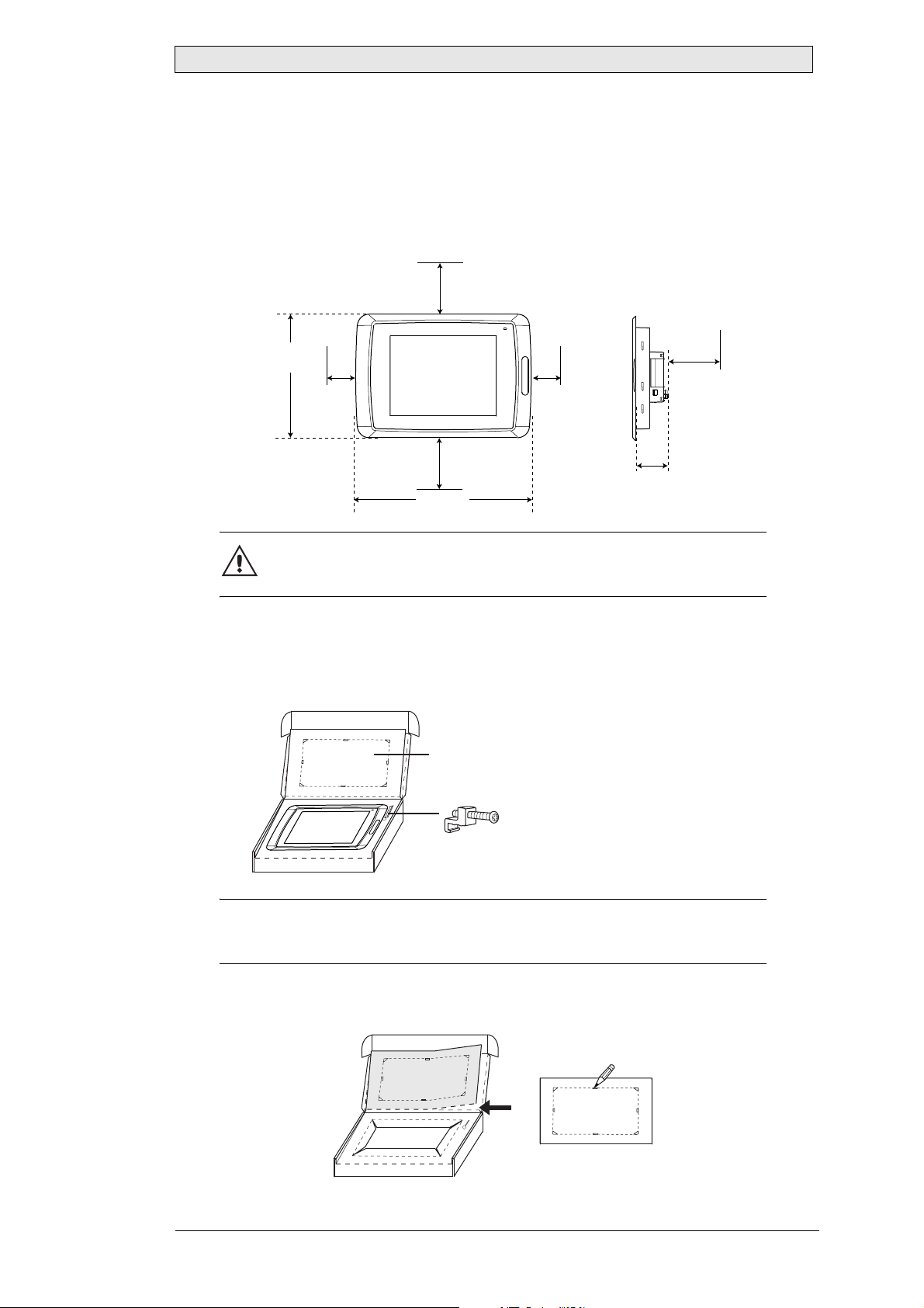
2.1 Space Requirements
– Installation plate thickness: 1.5 - 9.0 mm (0.06 - 0.35 inch)
– Space requirements when installing the operator panel:
100 mm
(4.0 inch)
304 mm
(11.97 inch)
50 mm
(2.0 inch)
100 mm
(4.0 inch)
398 mm
(15.67 inch)
50 mm
(2.0 inch)
Installation
100 mm
(4.0 inch)
60 mm
(2.36 inch)
Caution
The openings on the enclosure are for air convection. Do not cover these
openings.
2.2 Installation Process
1. Unpack and check the delivery. If damage is found, notify the supplier.
Panel cut out 355.5 x 278.5 mm
(14.0 x 10.96 inch)
x14
Note:
Place the operator panel on a stable surface during installation.
Dropping it or letting it fall may cause damage.
2. Place the panel cut out where the operator panel is to be situated, draw along the
outer sides of the holes and cut according to the markings.
Beijer Electronics, MAEN967 7
Page 8
Installation
3. Secure the operator panel in position, using all the fastening holes and the
provided brackets and screws:
x14
4. Connect the cables in the specified order.
0.5 - 1.0 Nm
A
Use an M5 screw and a grounding conductor (as short as possible)
B
with a cross-section of minimum 2.5 mm
C
D
Caution
Ensure that the operator panel and the controller system have the
same electrical grounding (reference voltage level), otherwise errors
in communication may occur .
2
.
Caution
- Use only shielded communication cables.
- Separate high voltage cables from sign al an d su pply cab l e s.
Caution
- The operator panel must be brought to ambient temperature
before it is started up. If condensation forms, ensure that the
operator panel is dry before connecting it to the power outlet.
- Ensure that the voltage and polarity of the power source is correct.
Power
CFCARD
B
1
Controller
RS422/RS485
RS232
C
24V DC
24V DC
D
A
Ethernet
5. Carefully remove the laminated film over the operator panel display, to avoid
static electricity that could damage the panel.
8 Beijer Electroni cs, MAEN967
Page 9
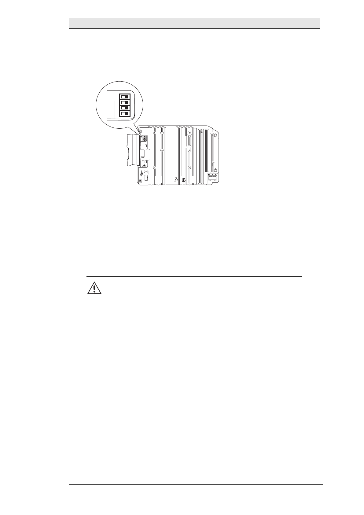
2.2.1 Mode Switches
All mode switches must be in OFF position during operator panel use.
The mode switches should not be touched unless by qualified personell.
MODE
1234
ON DIP
Installation
10/100
EXPANSION
RS232
24V DC
COM 2
1
MODE
1234
ON DIP
CF CARD
BUSY
COM 1
RS422
RS485
2.2.2 Connections to the Controller
For information about the cables to be used when connecting the operator panel to
the controller, please refer to the help file for the driver in question.
2.2.3 Other Connections and Peripherals
– Cables, peripheral equipment and accessories must be suitable for the application
and its environment. For further details or recommendations, please refer to the
supplier.
Caution
When using a compact flash card, do not remove the card when the busy
indicator is illuminated.
Beijer Electronics, MAEN967 9
Page 10

Installation
10 Beijer Electronics, MAEN967
Page 11
Technical Data
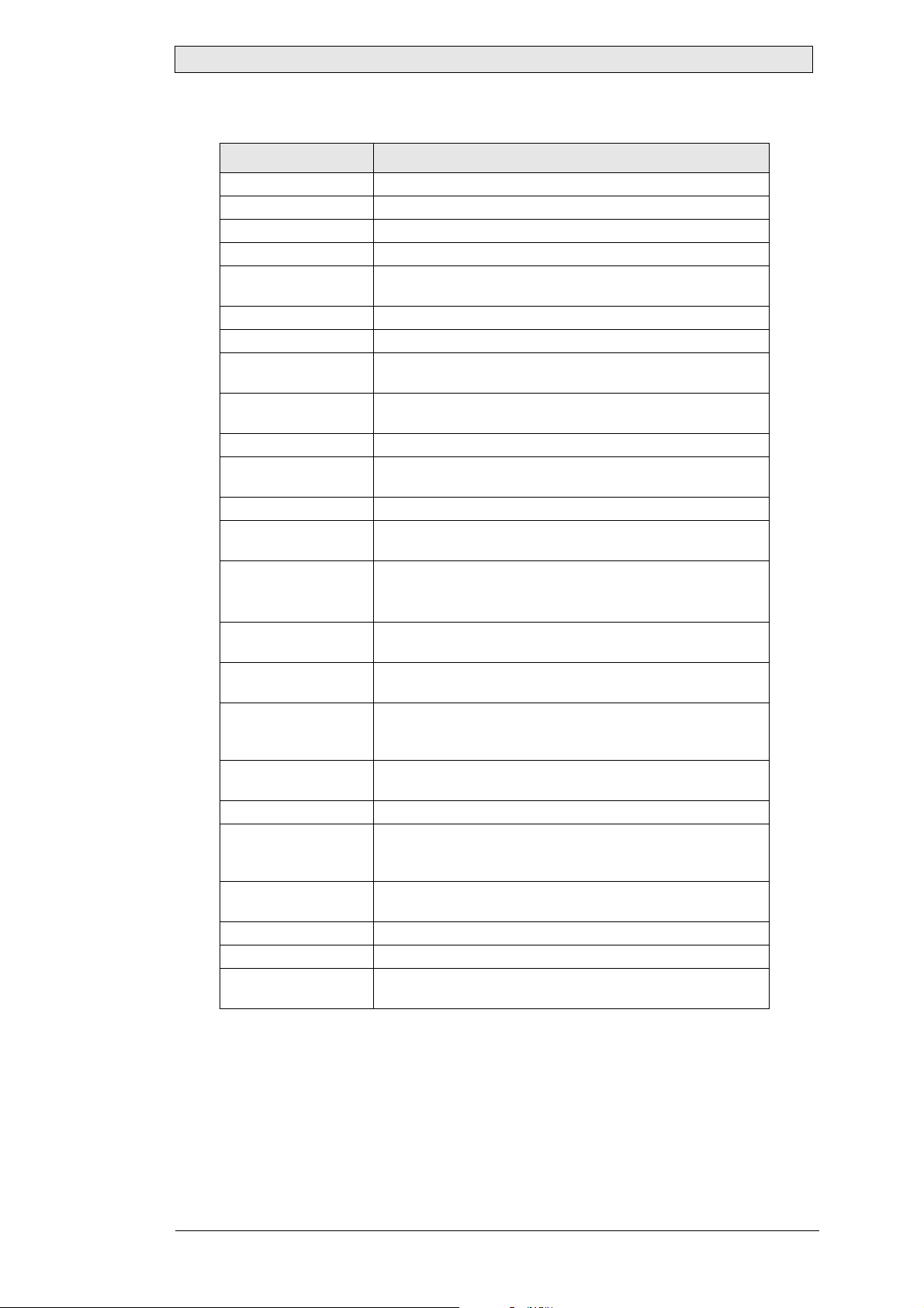
3Technical Data
Parameter EXTER T150-st
Front panel, W x H x D 398 x 304 x 6 mm
Mounting depth 60 mm (160 mm including clearance)
Front panel se al IP 66
Rear panel seal IP 20
Keyboard material/
Front panel
Reverse side material Powder-coated aluminum/blue-zink
Weight 4.9 kg
Serial port RS422/
RS485
Serial port RS232C 9-pin D-sub contact, male with standard locking screws 4-40
Ethernet Shielded RJ 45
USB Host type A (USB 1.1), max output current 500mA
CF-slot Compact flash, type I and II
Flash memory for
application
Real time clock ±20 PPM + error because of ambient temperature and supply
Real time clock
battery
Power consumption at
rated voltage
Display TFT-LCD. 1024 x 768 pix e ls, 64K color.
Active area of display,
W x H
Fuse Internal DC fuse, 3.15 AT, 5 x 20 mm
Power supply +24V DC (20 - 30V DC). Power supply connector.
Ambient temperature Vertical installation: 0 ° to +50 °C
Storage temperature -20 ° to +70 °C
Relative humidity 5 - 85 % non-condensed
CE approvals Noise tested according to EN61000-6-4 emission and
Touch screen: Polyester on glass, 1 million finger touch
operations.
25-pin D-sub contact, chassis-mounted female with
standard locking screws 4-40 UNC.
UNC.
Device type B (USB 1.1)
12 MB (incl. fonts)
voltage. Total maximum error: 1 min/month at 25 °C
Temperature coeff icient: 0.004 ppm/°C
CR2450
Minimum lifetime: 3 years
Normal: 1.2 A
Maximum: 1 .7 A
CCFL backlight lifetime at the ambient temperature of
+25 °C: >35,000 h.
304.1 x 228.1 mm
CE: The power supply must conform with the requirements
according to IEC 60950 and IEC 61558-2-4.
Horizontal installation: 0 ° to +40 °C
EN61000-6-2 immunity.
2
Beijer Electronics, MAEN967 11
Page 12

Technical Data
12 Beijer Electronics, MAEN967
Page 13

Chemical Resistance
4 Chemical Resistance
4.1 Metal Casing
The frame and casing material is stainless steel grade 316 / 1.4401 of outstanding
toughness, typically used in food processing, brewery and chemical/petrochemical
equipment.
Stainless steel grade 316 / 1.4401 has excellent corrosion resistance when exposed to
a range of corrosive environments and media.
4.1.1 Touch Screen Surface
The touch screen surface on the panel withstands exposure to the following solvents
without visible change:
Solvents Time
Acetone 10 minutes
Isopropanol 10 minutes
Toluene 5 hours
Beijer Electronics, MAEN967 13
Page 14

Chemical Resistance
14 Beijer Electronics, MAEN967
Page 15
Operator Panel Drawings
5Operator Panel Drawings
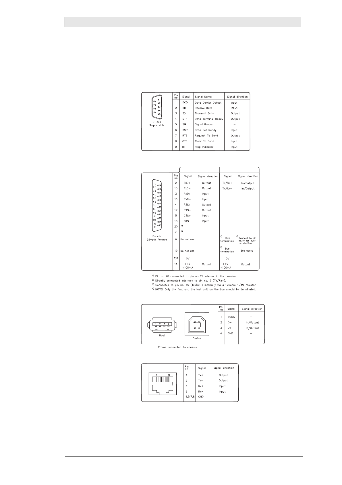
5.1 Communication Ports
RS-232
RS-422/485
USB
RS-422
RS-485
Ethernet
Drawing No. S-5005, Date 2004-10-27
Beijer Electronics, MAEN967 15
Page 16
Operator Panel Drawings
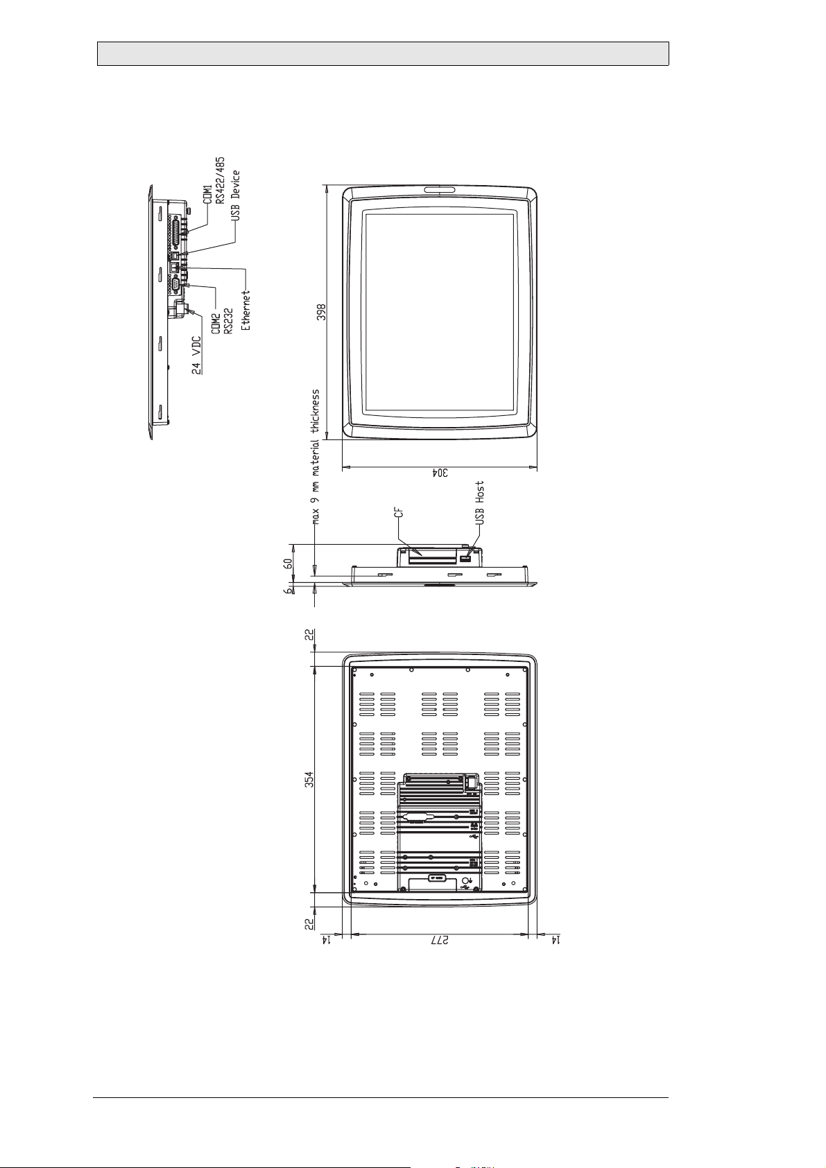
5.2 EXTER T150 Outline
Drawing No. S-5141, Date 2004-10-26
16 Beijer Electronics, MAEN967
Page 17
Additional Installation Tips
6 Additional Installation Tips
When experiencing communication problems in for example noisy environments or
when operating close to temperature limits, the following recommendations are to be
noticed.
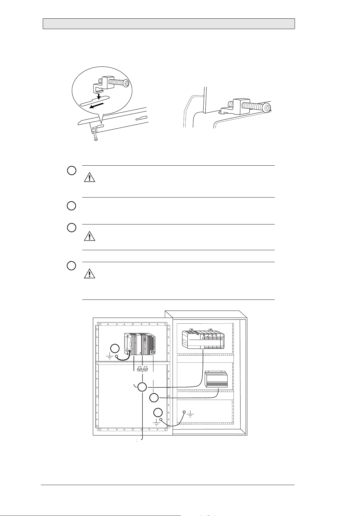
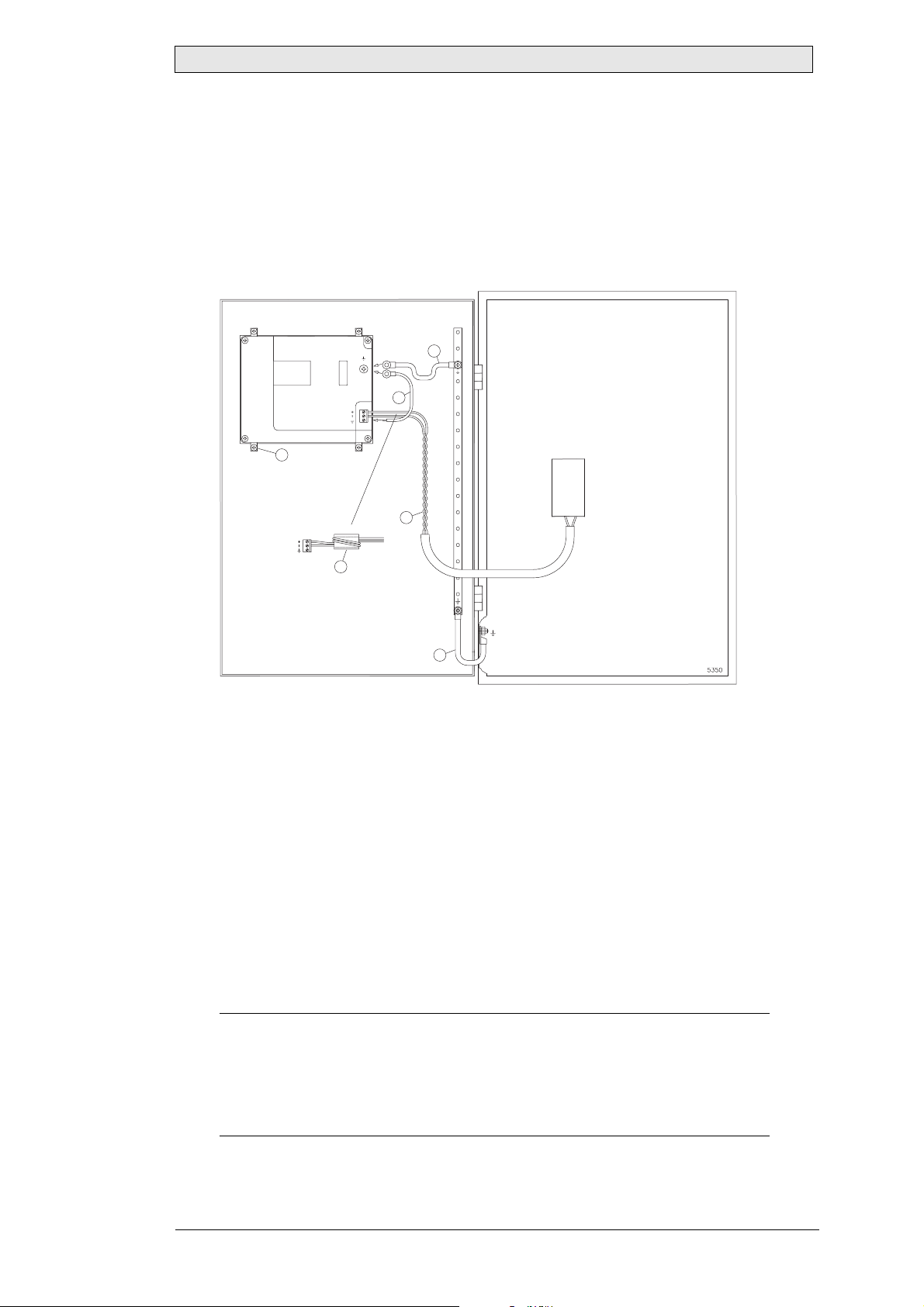
6.1 Grounding the Operator Panel
Door
Operator panel
1
Ferrite core
6
3
2
5
4
Mounting plate in the cabinet
Power supply
24 V DC
1. The operator panel’s mounting clamps do not provide a secure grounding connection between the panel and the device cabinet.
2. Connect a 2.5 mm
2
wire between the operator panel’s quick-connect plinth and
the panel chassis.
3. Connect a 6 or 4 mm
2
wire or grounding braid between the panel’s chassis and
the closest grounding point on the door.
4. Connect a strong but short grounding braid between the door and the device
cabinet.
5. Twist the cables onto the 24 V DC feed.
6. A ferrite core suppresses disturbances to the 24 V feed.
2 turns around the ferrite core provide 4 times the suppression of 1 turn.
3 turns around the ferrite core provide 9 times the suppression of 1 turn.
Remember:
The grounding wires should be short and the conductor should have a large area.
A long, thin grounding wire has a very high impedance (resistance) at high frequencies
and will not guide disturbances to the ground.
Multi-wire conductors are better than single wire conductors with the same area.
A braided conductor wire with the same area is even better.
The best is a short, thick groundin g braid.
Beijer Electronics, MAEN967 17
Page 18
Additional Installation Tips
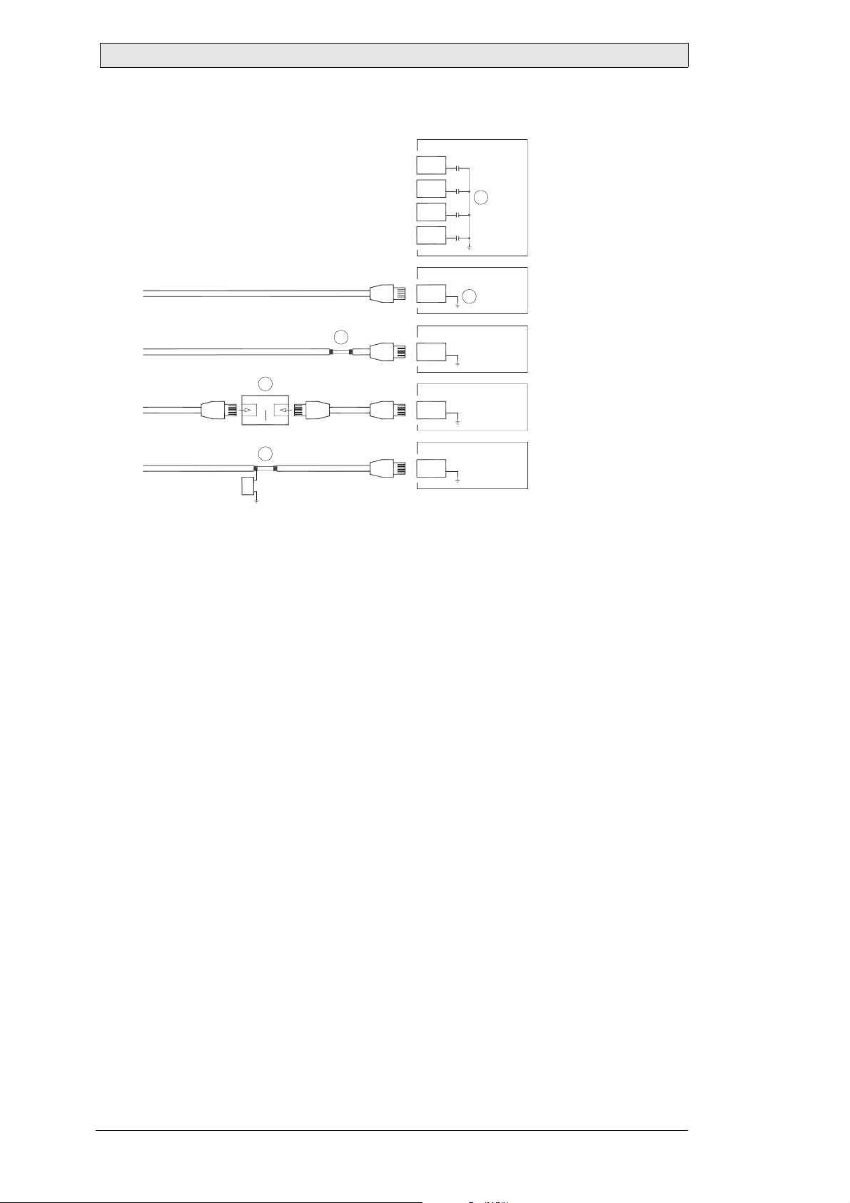
6.2 Ethernet Connection in the Panel
Industrial Ethernet
RJ45
RJ45
RJ45
RJ45
Operator panel
RJ45
1
2
Operator panel
RJ45
Operator panel
RJ45
Operator panel
RJ45
Shielded
0.1 uF
250 V
3
4
1-1
2-2
3-3
8-8
Short and
unshielded
5
1. In some industrial units for Ethernet, the RJ45 contact’s shield is connected to
the chassis via a capacitor.
2. The operator panel’s Ethernet shield is directly connected to the chassis.
Check whether the other Ethernet unit has its shield directly grounded or grounded
via a capacitor.
In many cases, connecting the shielded Ethernet cabling to the chassis at both ends
is inappropriate. Hum or grounding loops can occur. Unshielded cabling may even
result in fewer communication errors.
A good solution may be to use a shielded Ethernet cable, but to connect the shield at
one end only.
3. One option is to break the shield.
4. A more elegant method is to expand the shielded Ethernet cabling with a piece
of unshielded Ethernet cable.
5. You can ground the shield via an external 0.1 uF/250 V plastic capacitor. This
will connect the HF transients to the ground.
18 Beije r Electr onics, MAEN967
Page 19
Additional Installation Tips
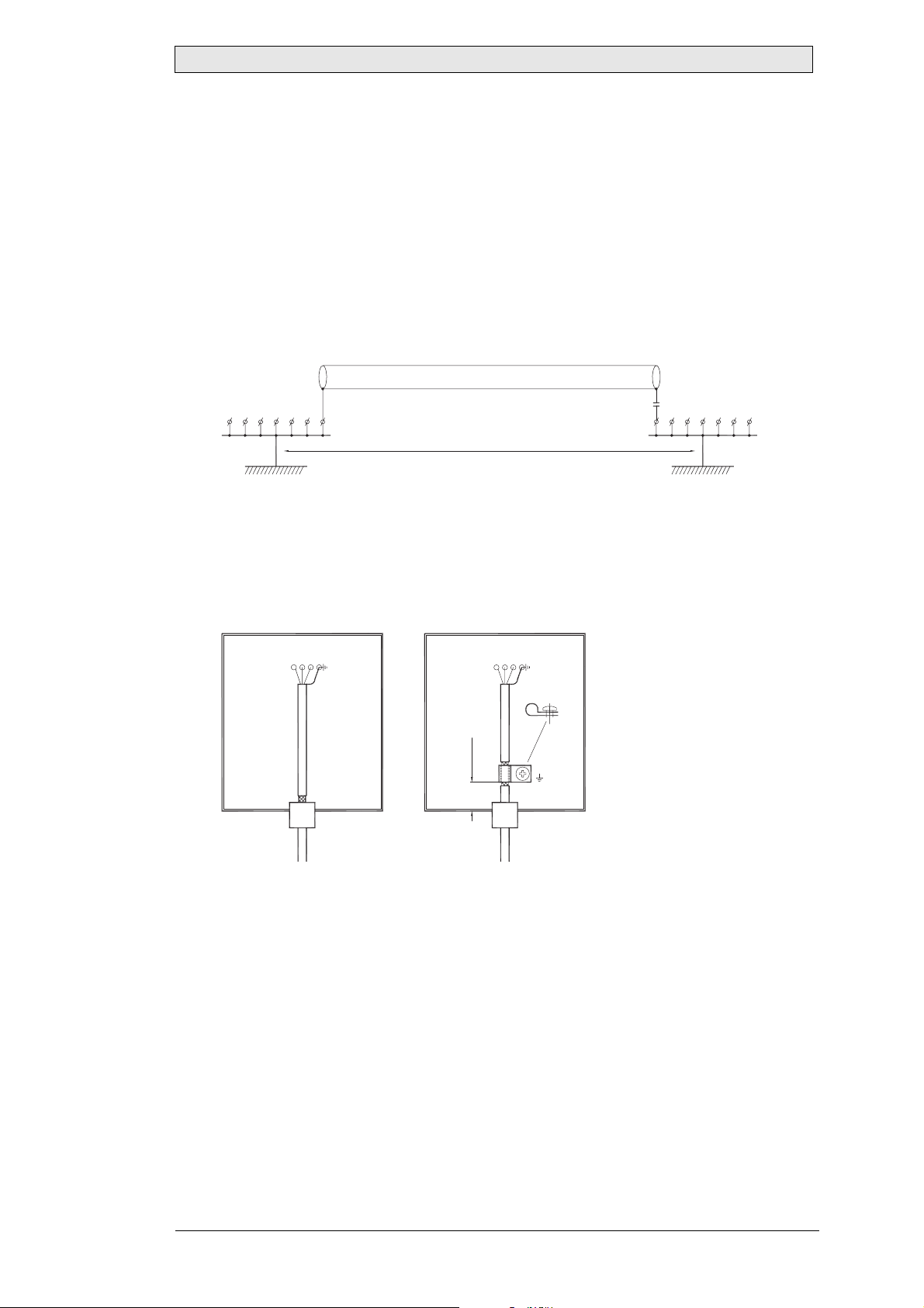
6.3 To Achieve Better EMC Protection
– Initially, use the original cabling from Beijer Electronics primarily.
– Use shielded cables for RS232 communication.
– Use twisted pair and shielded cabling for RS422 and RS485.
– Use the cabling intended for the bus type; Ethernet, Profibus, CC-Link, CAN,
Device Net etc.
– Install and connect according to applicable specifications for the relevant bus stan-
dard.
– Use shielded cabling for Ethernet, preferably with foil + braided shield.
– D-sub covers should be shielded, and the shield should be connected to the cover
360 ° where the cable comes in.
– Connect the shield at both ends.
Shielded cable
0.1 uF/250 V
Ground plane 1 Ground plane 2
Not same potential
Ground plate
With longer distances, there is a risk that the ground potential may be different. In
that case, the shield should only be connected at one end. A good alternative is to
connect the other end of the shield to the ground via a 0.1 uF/250 V plastic capacitor.
Both ends are then connected to the ground in terms of HF, but only connected to
the ground at one end in terms of LF, thus avoiding the 50 Hz grounding loops.
Metal cabinet Metal cabinet
Terminal or
connector
Terminal or
connector
Ground plate
in another building
Cable clamp
in steel
Short distance
EMC cable gland
Shielded cable Shielded cable
Plastic cable gland
– Use an EMC cable gland or regular plastic cable gland, remove the outer jacket
and connect the shield to the installation plate with a 360 ° metal cable clamp.
– Place the 24 V DC and communications cabling in one cable trunk/cable duct and
230/380 V AC in another. If the cables need to be crossed, cross them at 90 ° only.
Avoid combining the cabling for stronger 24 V DC outputs with the communi-
cation cabling.
– Ferrite cores that are snapped onto the shielded cabling may remove minor distur-
bances. Large ferrite pieces that are snapped onto unshielded cabling and where
the wires go 2-4 times around the cores are approximately 5-25 times more effi-
cient.
Beijer Electronics, MAEN967 19
Page 20
Additional Installation Tips
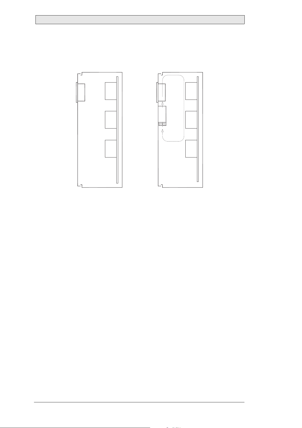
6.4 Ambient Temperature
The maximum ambient temperature for the operator panel is provided in the
specifications. The ambient temperature refers to the temperature in the device
cabinet which cools the panel’s electronics.
Top
° inside
Operator
panel
50
Power
°C outside
30
Middle
° inside
45
Bottom
° inside
40
Power
Power
Axial fan
120x120 mm
Airflow
5354
In most cases, the ambient temperature for the operator panel is significantly higher
than the device cabinet’s ambient temperature.
If the cabinet is tall and there are a number of heat-generating devices, the
temperature at the top of the cabinet will be considerably higher than the theoretical
temperature increase that would be expected. All electronics are sensitive to heat. The
lifespan of an electrolytic capacitor is cut in half with an 8-10 ° increase in
temperature. A 15-20 ° temperature increase results in a quarter of the lifespan etc.
Rittal has a good program for estimating the anticipated average temperature in the
cabinet as well as a large program for controlling the temperature in the device
cabinet.
An enamel-coated steel cabinet has a radiant heat value of 5.5 W/m
2
and degrees C.
Installing a fan inside the cabinet will even out the temperature, while moving air
provides considerably better cooling than still air. A suitable fan is a 120 x 120 mm
axial fan, available in 24 V DC, 115 and 230 V AC.
Install the fan so that it sits in the cooler area and will blow cold air against the
operator panel. If the fan is mounted at the top and sucks air upwards, the fan’s
ambient temperature will be higher = shorter lifespan.
A good fan with a ball-bearing mounting has an expected lifespan of at least 40,000
hours (not a guaranteed lifespan) at 40 °C. This corresponds to at least 4 years of
continuous use. If a thermostat is installed, the fan only needs to come on when
needed.
Large graphic terminals draw only one fifth of the current when the background
lighting is off. The loss effect drops from e.g. 25 W to only 5 W.
The operator panel’s loss effect = supply voltage x current. Virtually no power goes
to external users and no loss effects due to inputs.
20 Beije r Electr onics, MAEN967
Page 21
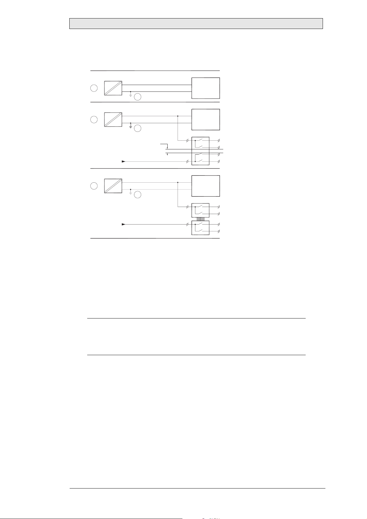
6.5 Safety
Most of the operator panels are fed with 24 V DC.
Power supply
230 V AC to 24 V DC
1
Power supply
230 V AC to 24 V DC
2
Power supply
230 V AC to 24 V DC
3
+24 V
0 V
4
+24 V
0 V
4
Distance?
+24 V
0 V
4
230 V AC
Operator panel
Operator panel
Operator panel
Small controller with expansion unit
COM1
COM100
Ch0
Ch1
Ch100
Ch101
5355
Additional Installation Tips
1. If you use a power supply that meets safety standards and only feeds the operator
panel, there is no problem.
2. However, if you have a 24 V unit that also feeds other units, there is reason to be
cautious.
The operator panel does not have insulation that meets safety requirements in
the event of a potential short circuit between 230 V AC and 24 V DC. It is
assumed that the 24 V feed is secure, for example, SELV according to
EN 60950 (protection against electric shock) and UL 950.
Example:
Here is an example that explains why a secure 24 V DC feed can be ruined by mixing 24
V relay contacts with 230 V AC relay contacts in a smaller controller. Check that the
“clearances and creepage distances between 24 V DC and 230 V AC fulfill EN 60950 or
UL 950”. If not, input a separate 24 V unit into the operator panel.
3. If there is a substantial distance between the relay contacts for 24 V DC and
230 V AC, it is OK to use the same 24 V devices for all feeds.
4. Connect 0 V on the 24 V feed to the ground. This offers three advantages:
–Safety is increased. The 24 V feed will not be live in the event of a faulty connec-
tion or short circuit between 0 V (24 V) and 230 V phase.
–Transients on the 24 V feed are connected to the ground.
–No risk that the 24 V feed is at a high level in relationship to the ground. This is
not unusual since there is high static electricity.
Beijer Electronics, MAEN967 21
Page 22
Additional Installation Tips
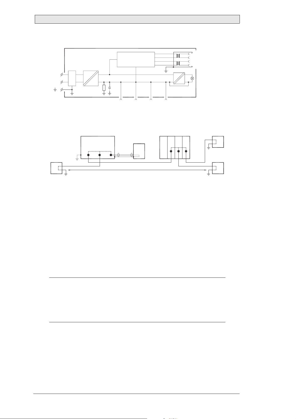
6.6 Galvanic Isolation
+24 V DC
0 V
Filter
DC/DC
galvanic isolation
1.5 m
Internal electronic
VCC
0 V (GND)
RS422/485 RS232 USB USB
DC/AC
Ethernet
CFL
5356
The operator panel has galvanic isolation against the 24 V DC feed but no galvanic
isolation between the communication ports for RS232, RS422/485 and USB. Only
the Ethernet connection has galvanic isolation.
Operator panel
RS422 RS232 USB
PC
* *
**
*
Not same ground potential
* = Internal 0 V (GND) connection
Modular controller
CPU COM COM2Power
***
Printer
*
PC
When a PC is connected to the panel, the panel’s internal 0 V (GND) will be
connected to the protective ground via the PC.
A number of USB devices can have the shield connected together with the protective
ground. Here, the panel’s 0 V (GND) is connected to the protective ground when,
for example, a USB memory stick, keyboard or similar device is plugged in.
If a number of units are connected that have a 0 V and a ground connection, and
these are connected to various grounding points, there is a substantial risk of
problems. Grounding currents go through communication cables, the rear plate of
the controller, and internally in the operator panel, and can cause errors.
Use external units to improve communication and achieve galvanic isolation.
Westermo has good industry-standard insulators that are also insulated from the 24
V DC feed.
Note:
It is very important to make sure that the 24 V feed in the external insulation unit is
not connected to one of the communication outlets. If it does not have 100% insulation
against the 24 V feed, disturbances and grounding currents from the 0 V on the 24 V
side will disrupt communication.
Using this type of unit solves one problem but creates a larger problem!
A substandard installation may work now, but problems may arise when other devices
are connected.
22 Beije r Electr onics, MAEN967
Page 23
Additional Installation Tips
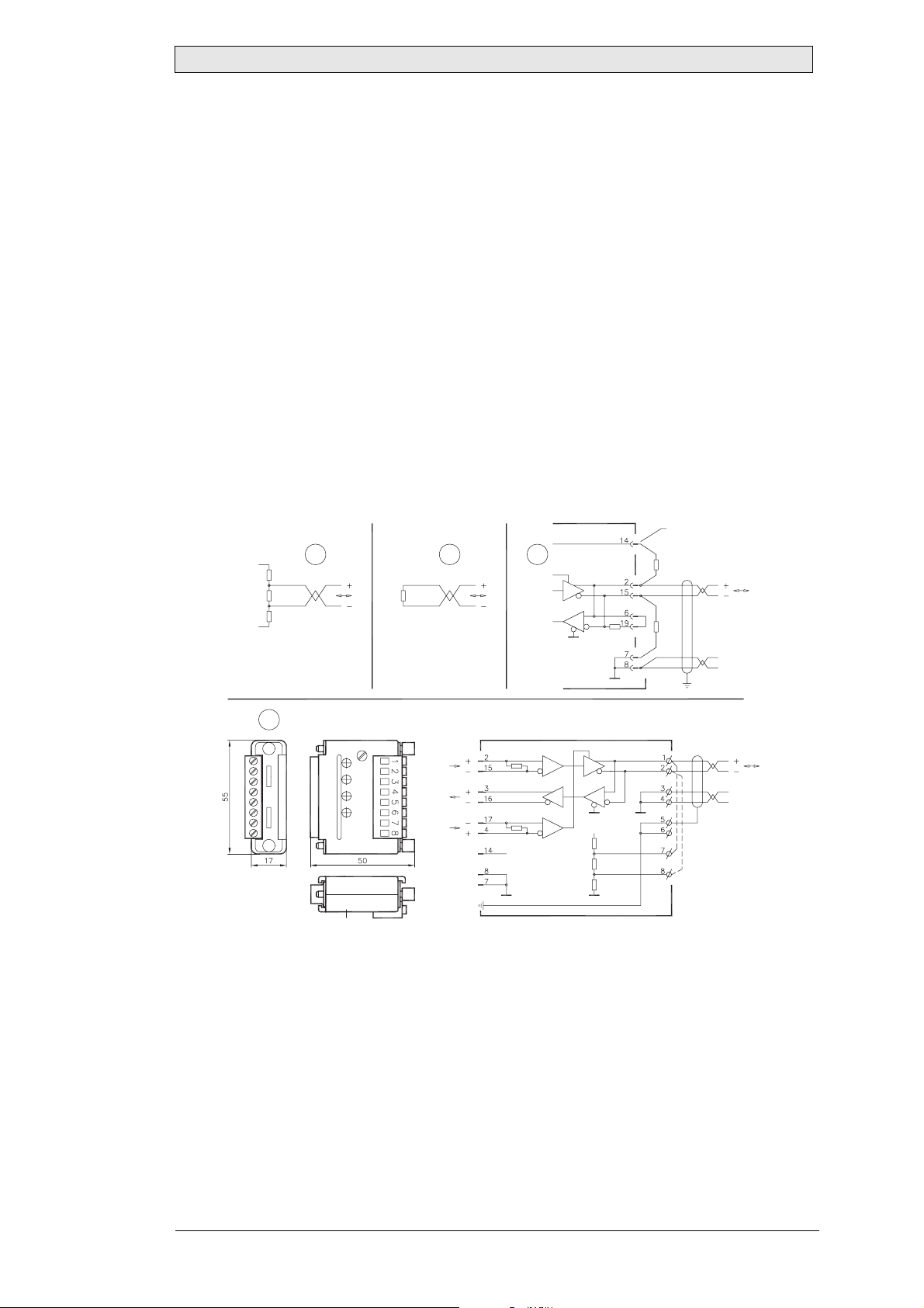
6.7 Cable and Bus Termination RS485
– Use shielded and twisted pair cable.
The pair capacitance may not exceed 52.5 pF/m and area at least 0.25 mm
24), if you want to use the maximum transfer distance and maximum transfer
speed.
– 0 V, the reference voltage for communication should be included in the cabling.
With two-way communication use two pairs; one pair for communication and
one pair for 0 V.
– The shield must be grounded at one end. The other end is usually grounded, but
with longer distances or when there is a difference in the ground potential, the
shield should be connected to the ground via 0.1 uF/250 V plastic capacitor to
prevent ground current in the braided shield.
A number of manufacturers recommend that the shield be grounded at each node.
Various manufacturers have different systems for bus termination. The RS485
standard does not describe how the “Fail Safe” function would be carried out, just
that the system should be able to handle the error.
Depending on the recipients’ design, the bus wires may be on the same level or
require pull-up or pull-down to ensure that no faulty signals are detected when the
bus is in resting mode (all transmitters are disconnected).
Inside operator panel
+5 V
+5 V
1 23
1K
120 ohm
1K
0 V
120 ohm
(120 ohm)
1K
1K
2
(AWG
0 V
0 V
4
CAB8
Operator
panel
RS422
+5 V
0 V
0 V
VCC
CAB8
2.65 V
2.35 V
VCC
1K
120 ohm
1K
Bus
RS485
0 V
0 V
Shield
Bus termination
5358
1. Some (older) operator panels had pull-up and pull-down resistance except for
the actual bus termination at 120 ohm, similar to Westermo and Profibus.
2. Newer panels have another type of recipient, so-called built-in “Fail Safe”, where
simple bus termination resistance is sufficient.
If other nodes on the RS485 network require pull-up and pull-down and the
operator panel is at one end of the loop, one of the following procedures can be
carried out:
3. Connect two 1k/0.25 W resistors in the 25-pole D-sub contact. Set jumper pins
6-19.
4. Use CAB8. It offers the option of bus termination with pull-up/-down. It is also
easy to connect the bus cable via the screw terminal block.
Beijer Electronics, MAEN967 23
Page 24

HEAD OFFICE
SWEDEN
Beijer Electronics Products AB
Box 426
SE-201 24 Malmö, Sweden
Tel: +46 40 35 86 00
Fax: +46 40 93 23 01
info@beijerelectronics.com
SUBSIDIARIES
GERMANY
Elektronik-Systeme Lauer GmbH & Co. KG
Kelterstraße 59
72669 Unterensingen, GERMANY
Tel: +49 7022 96 60 0
Fax: +49 7022 9660 103
info@lauer-hmi.com
TAIWAN
Hitech Electronics Corp.
7 & 8 F, No. 108 Min-Qua n Ro a d
Shin-Tien, Taipei Shien, TAIWAN, R.O.C. 231
Tel: +886-2-2 218-3600
Fax: +886-2-2218-9547
info.hmi@hitech-lcd.com.tw
USA
Beijer Electronics Inc.
939 N. Plum Grove Road, Suite F
Schaumburg, IL 60 1 73, USA
Tel: +1 847 619 6068
Fax: +1 847 619 6674
info.usa@beijerelectronics.com
CHINA
Beijer Electronics Co. Ltd
Room 201, Buildning B, No. 1618,
Yishan Road, Sh an ghai 201103, CHINA
Tel: +86 21 6145 0400
Fax: +86 21 6145 0499
info@beijerelectronics.cn
 Loading...