

Page 1

iXPanelT150
Service&MaintenanceManual
MAEN008,2010-05
English
Page 2

Service&Maintenance manualforiXPanelT150
Foreword
This manual contains detailed information about iX PanelT150, including
descriptions of various actions that canbe carried out in order to maintain or
update the operator panel hardwareand software.
The manual contains descriptions of basic maintenance and replacement of
common parts in iX PanelT150.
The manual assumes that the most recent versions of the system program
(firmware) and iX Developerare used.
The following othermanuals are available for iX Panel T150:
iX PanelT150 installation manual (MAEN988x) for information regarding
installation.
iX Developer referencemanual (MAEN831x) for a description of the
configuration tool.
iX Developer user’s guide (MAEN832x) for function-based descriptions.
Foreword
© Beijer ElectronicsAB, MAEN008, 2010-05
The information in this documentis subject to changewithoutnoticeandisprovidedasavailableatthe
time of printing. Beijer ElectronicsAB reserves the right to change any information without updating this
publication. Beijer Electronics AB assumes no responsibility for any errors that may a p pear in t his document.
Read the entire installation manualprior toinstalling and using this equipment. Only qualified personnel
may install, operate or repair this equipment. BeijerElectronics AB is not responsiblefor modified, altered
or renovated equipment. Because the equipment hasa wide rangeofapplications,usersmustacquirethe
appropriate knowledge to use the equipment properly in their specific applications. Personsresponsible
for the application and the equipment must themselves ensure that each application is in compliance with
all relevant requirements,standards and legislationinrespecttoconfigurationandsafety. Onlypartsand
accessories manufactured according to specifications set by Beijer Electronics AB may be used.
BEIJER ELECTRONICSAB SHALL NOT BE LIABLE TOANYONE
FOR ANY DIRECT, INDIRECT, SPECIAL, INCIDENTAL OR
CONSEQUENTIAL DAMAGESRESULTINGFROM THE
INSTALLATION, USE OR REPAIR OF THIS EQUIPMENT, WHETHER
ARISING IN TORT, CONTRACT, OR OTHERWISE. BUYER'S SOLE
REMEDYSHALL BE THE REPAIR, REPLACEMENT,OR REFUND
OF PURCHASE PRICE, AND THE CHOICE OF THE APPLICABLE
REMEDYSHALLBEATTHESOLEDISCRETIONOFBEIJER
ELECTRONICSAB .
BeijerElectronics, MAEN008
Page 3

Contents
Contents
1 Safety Precautions ....................................................... 5
1.1 General ...........................................................
1.2 During Installation ..............................................
1.3 DuringUse .......................................................
1.4 Service and Maintenance ........................................
1.5 Dismantling and Scrapping .....................................
2 Introduction ............................................................. 7
2.1 iX PanelT150 ....................................................
2.2 Maintenance .....................................................
2.3 Service andRepairs ..............................................
2.4 Dismantling and Scrapping .....................................
2.5 Contact andSupport ............................................
3 Installation ............................................................... 10
3.1 SpaceRequirements .............................................
3.2 InstallationProcess ..............................................
3.2.1 ConnectionstotheController .............................. ....
3.2.2 OtherConnectionsand Peripherals ...................... .......
4 Technical Data ........................................................... 14
5 Chemical Resistance .................................................... 15
5.1 MetalCasing .....................................................
5.2 Touch Screen and Overlay ... ....................................
5.2.1 Autotex F157/207 ....... ........................................
5.2.2 TouchScreen Surface ................ ............................
5.2.3 AutoflexEB ..... .................................................
6 Hardware Tests .......................................................... 18
7 Additional Hardware ................................................... 19
7.1 Memory Card ....................................................
7.1.1 Installation ............... ........................................
7.1.2 SettingsiniX Developer ................... ......................
8 Hardware Replacement ................................................. 21
8.1 Mode Switches ...................................................
8.2 Cables .............................................................
8.3 Replacing the Rear Co
8.4 Replacing the Displa
8.4.1 Self-test of the Dis
8.4.2 Calibrating theTouch Screen .. ..................................
ver ........................................
y/Display Cable . .........................
play .............................. .............
8.5 ReplacingtheCompleteFront ..................................
8.6 Replacing the Backlight .........................................
8.7 AvailableSpare Parts for iX Panel T150 .........................
9 Service Menu ............................................................ 30
9.1 Service Menu in an Empty Panel ...............................
9.2 Service Menu in a Panel with Project ...........................
9.3 ServiceMenu Options ...........................................
9.3.1 IP Settings ... ................................................ ....
9.3.2 Date/Time ........................ ...............................
10
10
13
13
15
16
16
17
17
19
19
20
21
22
23
24
25
25
27
28
29
30
30
30
30
30
5
5
6
6
6
7
8
8
8
9
BeijerElectronics, MAEN008
Page 4

Contents
9.3.3 Erase Project ................................................. ....
9.3.4 Format Memory Card .............................. .............
9.3.5 TouchCalibrate .................. ...............................
31
31
31
10 Hardware Self Test ...................................................... 32
11 Additional Installation Tips .. .......................................... 33
11.1 Grounding the Operator Panel .................................
11.2 Ethernet Connection in the Panel ..............................
11.3 To Achieve Better EMC Protection .............................
11.4 Ambient Temperature ...........................................
11.5 Safety .............................................................
11.6 Galvanic Isolation ................................................
11.7 Cable and Bus Termination RS485 .............................
33
34
35
36
37
38
39
12 Fault Tracing ............................................................. 40
13 Software .................................................................. 42
13.1 General Information about Software ...........................
13.1.1 Software Products .......... .....................................
13.2 Update Software .................................................
13.2.1 iX Developer ......................... ............................
13.2.2 RemoteAccess Viewer ......... ..................................
13.2.3 SystemProgram .................................... .............
42
42
43
43
43
43
14 Environmental Aspects ................................................. 45
14.1 General Environmental Aspects ................................
14.2 Environmental Impact of the OperatorPanels .................
14.2.1 Mechanical Components ................................. .......
14.2.2 Electronics ........................ ...............................
14.3 Recycling .........................................................
14.4 Environmental Impact Report ..................................
45
45
45
45
46
46
BeijerElectronics, MAEN008
Page 5

Safety Precautions
1SafetyPrecautions
Both the installer and the owner and/or operatorof the operator panel must read
and understand this installation manual.
1.1 General
• Read the safety precautions carefully.
• Check the delivery for transportation damage. If damage is found, notify the
supplier as soon as possible.
• Do not use the operator panel in an environment with high explosive hazards.
• The supplier is not responsible for modified, altered or reconstructed
equipment.
• Use only parts and accessories manufactured according to specifications of
the supplier.
• Read the installation and operating instructions carefully before installing,
using or repairing theoperator panel.
• Neverallowfluids,metalfilingsorwiringdebristoenteranyopeningsinthe
operator panel. This may cause fire or electrical shock.
• Only qualified personnel may operate the operator panel.
• Storing the operator panel where the temperature is lower/higher than
recommended in this manual can cause the LCDdisplay liquid to
congeal/become isotopic.
• The LCD display liquid contains a powerful irritant. In case of skin contact,
wash immediately with plenty of water. In case of eye contact, hold the eye
open,flushwithplentyofwaterandgetmedicalattention.
• Thefiguresinthismanualservesanillustrativepurpose. Becauseofthemany
variables associated with any particular installation, the supplier cannot
assume responsibility for actual use based on the figures.
• The supplier neither guarantees that the operator panel is suitable for your
particular application, nor assumes responsibility for your product design,
installation or operation.
1.2 DuringInstallation
• The operator panel is designed for stationary installation on a plane surface,
where thefollowing conditions are fulfilled:
– no high explosive risks
– no strong magnetic fields
– no direct sunlight
– no large, sudden temperature changes
• Install the product accordingto the accompanying installation instructions.
• Ground the product accordingto the accompanying installation instructions.
• Only qualified personnel may install the operator panel.
• Separate the high voltage, signal and supply cables.
• Make sure thatthe voltage and polarity of the power source is correct before
connecting the productto the power outlet.
• Peripheralequipment must be appropriate for the application and location.
BeijerElectronics, MAEN008
5
Page 6

Safety Precautions
1.3 DuringUse
• Keep the operator panel clean.
• Emergency stop and other safety functions may not be controlled from the
operator panel.
• Do not use too much force or sharp objects when touching the keys, touch
screenetc.
1.4 ServiceandMaintenance
• Only qualified personnel should carry out repairs.
• The agreed warranty applies.
• Before carrying out any cleaning or maintenance operations, disconnect the
equipment from the electrical supply.
• Clean the display and surrounding front cover with a soft cloth and mild
detergent.
• Replacing the battery incorrectly may result in explosion. Only use batteries
recommended by the supplier.
1.5 DismantlingandScrapping
• The operator panel or parts thereofshall be recycled acc
regulations.
• The following components contain substances t
to health and the environment: lithium batter
display.
hat might be hazardous
y, electrolytic capacitor and
ording to local
BeijerElectronics, MAEN008
6
Page 7
Introduction
2Introduction
This manual describes how to maintain the iX Panel T150.
The functions available in iX Developer depend on which operator panel model is
used.
2.1 iXPanelT150
The following drawingsare available for iX PanelT150:
• Outline drawing
• Panelcut-out
BeijerElectronics, MAEN008
7
Page 8

Introduction
2.2 Maintenance
Carefully read the instructions before beginning maintenance on the operator
panel.
• Only qualified personnel should carry out maintenance.
• The agreed warranty and license agreements apply.
• Any damage to the operator panel caused by personnel invalidates the
warranty.
• Before carrying out any cleaning or maintenance operations, disconnect the
operator panel from the powersupply.
• Clean the display and surrounding front cover with a soft cloth and mild
detergent. Recommended cleaning fluids for the display are water and IPA
(Isopropyl Alcohol or Hexane).
• Replacing the battery incorrectly may result in explosion. Only use batteries
recommended by the supplier.
• A 6-month warranty on allservice parts is provided.
Maintenance personnel are permitted to carry out the following actions:
• Replacing the Rear Cover
• Replacing the Display/Display Cable
• Replacing the Complete Front
• Replacing the Backlight
2.3 ServiceandRepairs
• Only accredited companies are permitted to p erform service and repairs.
• Ifanon-accreditedcompanyconductsanykindofserviceorrepair,theagreed
warranty will be invalidated.
• If training is required, contact the supplier.
• All maintenance should be performed in a 15-30 °C temperature range.
• Any damage to the operator panel caused by personnel invalidates the
warranty.
• Contracts with customers supersede the information in thisd ocument.
2.4 DismantlingandScrapping
• The operator panel, or parts thereof,should be recycled according to l ocal
regulations.
• The following components contain substances that might be hazardousto
health and the environment: lithium battery, electrolytic capacitor, display.
BeijerElectronics, MAEN008
8
Page 9

Introduction
2.5 ContactandSupport
If you want to report a fault or have a question about the operator panels, please
contact your local supplier orfill out the form on the web site.
1.
Enter the web site www.beijerelectronics.comand select Support.
2.
Select Contact in themenu. Make sure to provide information about type
number, serial number, environment and an installation description.
The form will be sent to the manufacturer’s help desk and they will answer your
question or register your improvement/fault.
To ensure quick resolution, provide as many details as possible in your report.
Include the date and time when the problem occurred,a description of what you
were trying to do, the detailed steps you took that led up to the problem, and
details about any error messages received.
BeijerElectronics, MAEN008
9
Page 10
3Installation
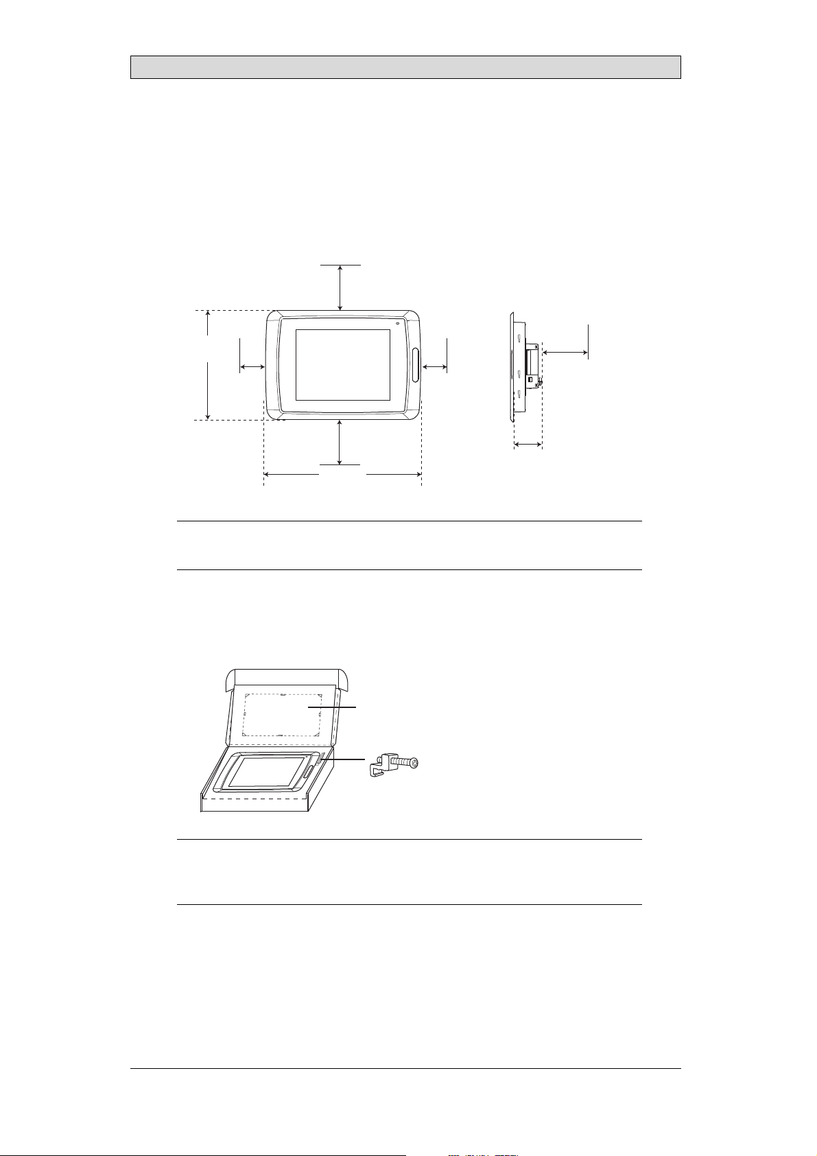
3.1 SpaceRequirements
• Installation plate thickness: 1.5 - 9.0 mm (0.06 - 0.35inch)
• Space requirementswhen installing the operator panel:
100 mm
(4.0 inch)
304 mm
(11.97 inch)
50 mm
(2.0 inch)
100 mm
(4.0 inch)
398 mm
(15.67 inch)
50 mm
(2.0 inch)
60 mm
(2.36 inch)
Installation
100 mm
(4.0 inch)
Caution:
Theopenings ontheenclosurearefor airconve
ction. Donotcovertheseopenings.
3.2 InstallationProcess
1.
Unpack and check the delivery. If
Note:
Placethe operatorpanelonastablesurfaceduringinstallation.
Droppingitorlettingitfallmaycausedamage.
damage is found, notify the supplier.
Panel cut out 355.5 x 278.5 mm
(14.0 x 10.96 inch)
x 14
BeijerElectronics, MAEN008
10
Page 11
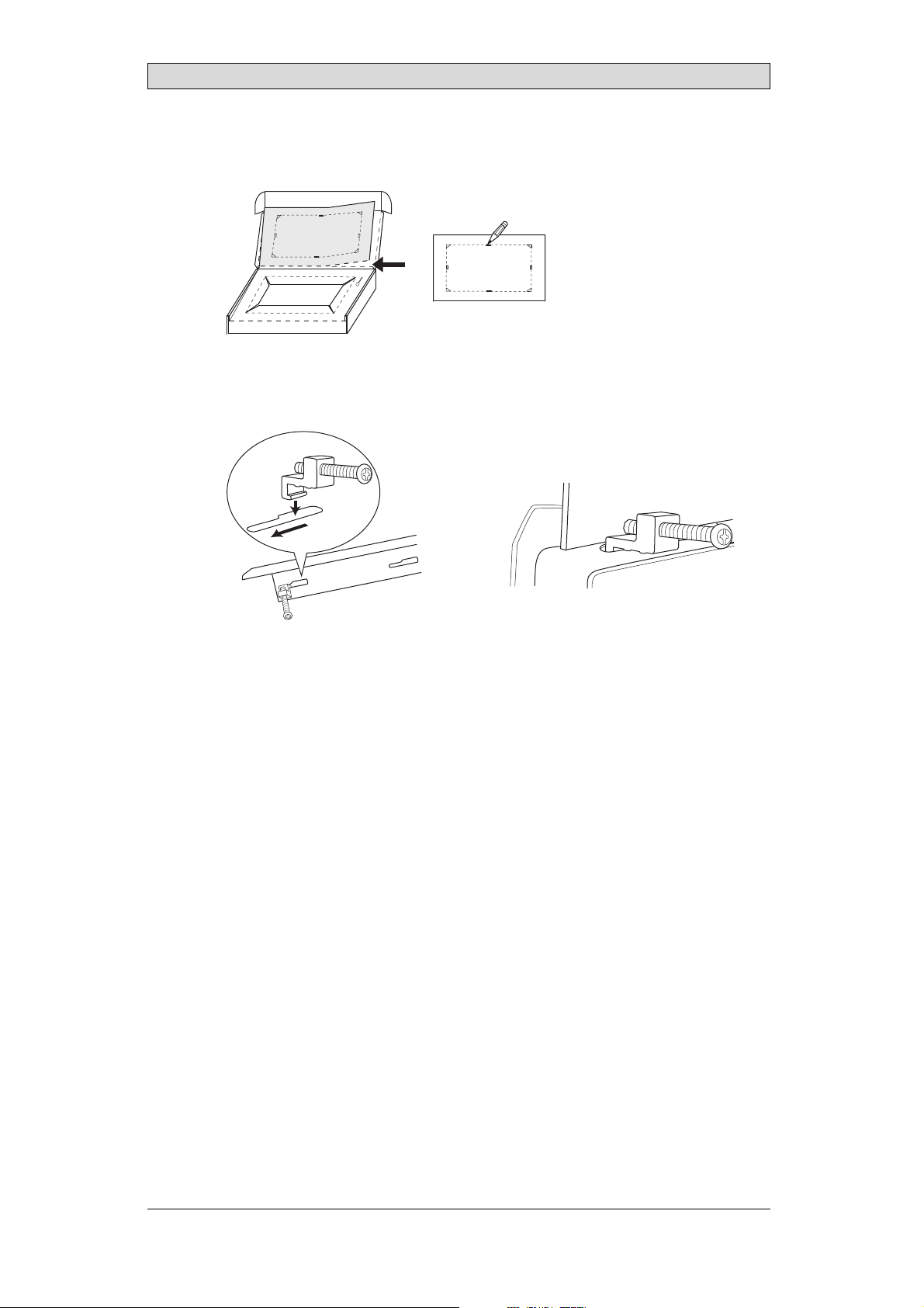
2.
Place the panel cut out where the operator panel is tobe situated, draw along
the outer sides of the holes and cut according to the markings.
3.
Secure theoperator panel in position, using all the fastening holes and the
provided brackets and screws:
x 14
Installation
0.5 - 1.0 Nm
BeijerElectronics, MAEN008
11
Page 12
Installation
4.
Connect the cables in the specified order,according to the drawing and steps
below.
Caution:
• Ensurethattheoperator panelandthecontrollersystemhavethe sameelectrical
grounding(referencevoltagelevel),otherwiseerrorsincommunicationmay
occur.
• Theoperatorpanelmust bebroughttoambienttemperaturebeforeitisstarted
up. Ifcondensationforms,ensurethattheoperator panelisdrybeforeconnecting
itto thepoweroutlet.
• Ensurethatthevoltageandpolarityofthepowersourceiscorrect.
• Useonlyshieldedcommunicationcables.
• Separatehighvoltagecablesfromsignalandsupplycables.
Power
CF CARD
B
1
Controller
RS422/RS485
RS232
24V DC
24V DC
C
D
A
Ethernet
– Connect cable A.
– Connect cable B, using an M5 screw and a grounding conductor (as short
as possible) with a cross-section of minimum 2.5 mm
– Connect cable C.
– Connect cable D.
5.
Carefully remove the laminated film overthe operator panel display,to avoid
2
.
static electricity that could damage the panel.
BeijerElectronics, MAEN008
12
Page 13

Installation
3.2.1 ConnectionstotheController
Forinformation about the cables to be used when connecting the operator panel to
the controller,please refer to the help file for the driver in question.
3.2.2 OtherConnectionsandPeripherals
Cables, peripheral equipment and accessories must be suitable for the application
and its environment. Forfurther details or recommendations, please refer to the
supplier.
Caution:
Whenusingacompactflashcard,donotremovethecardwhen thebusyindicatoris
illuminated.
BeijerElectronics, MAEN008
13
Page 14
Technical Data
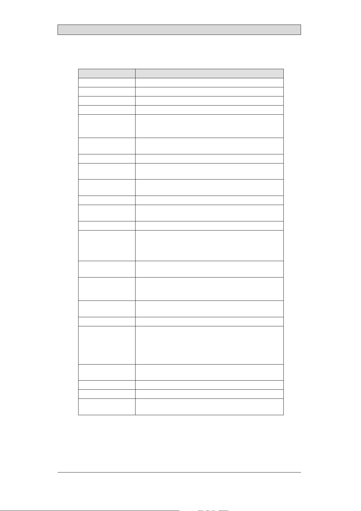
4TechnicalData
Parameter iXPanelT150
Frontpanel,WxHxD 398x304x6mm
Mountingdepth 60mm (160mmincludingclearance)
Frontpanel seal IP66
Rear panel seal IP 20
Keyboard
material/Front
panel
Reverseside
material
Weight 3.7 kg
Serialport
RS422/RS485
SerialportRS232C 9-pinD-subcontact,malewithstandardlocking screws4-40
Ethernet ShieldedRJ45
USB HosttypeA(USB1.1),maxoutputcurrent500mA
CF-slot Compactflash,typeIandII
Realtimeclock ±20PPM +errorbecauseofambienttemperatureandsupply
Power consumption
atrated voltage
Display TFT-LCD.1024x768pixels,64Kcolors.
Activeareaof
display,Wx H
Fuse InternalDCfuse,3.15AT,5x20mm
Powersupply +24V DC(20-30V DC).Powersupplyconnector.
Ambient
temperature
Storagetemperature -20° to+70°C
Relativehumidity 5- 85%non-condensed
Approvalsand
certifications
Touchscreen: Polyesteronglass,1millionfingertouch
operations. Overlay: AutotexF157orF207*.
Powder-coatedaluminum
25-pinD-sub contact,chassis-mountedfemalewith
standardlockingscrew s 4-40UNC
UNC
DevicetypeB(USB1.1)
voltage. Totalmaximumerror: 1min/monthat25°C.
Temperature coefficient: -0.034±0.006ppm/°C
Rechargeablebattery.
Normal: 1.2A
Maximum: 1.7A
CCFLbacklight lifetimeattheambienttemperatureof
+25°C:>35,000h.
304.1x 228.1mm
CE:The powersupplymustconformwiththerequirements
accordingtoIEC60950andIEC61558-2-4.
ULand cUL:Thepowersupplymustconformwiththe
requirementsforclassIIpowersupplies.
Verticalinstallation: 0°to+50°C
Horizontalinstallation: 0°to +40°C
Informationisavailableonthewebsite
www.beijerelectronics.com
2
*SeesectionChemicalResistancefor moreinformation.
BeijerElectronics, MAEN008
14
Page 15
Chemical Resistance
5 ChemicalResistance
5.1 MetalCasing
The frame and casing material is powder-coatedaluminum. This powder paint
withstands exposure to the followingchemicals without visible change:
Aceticacid 10% Phosphoricacid4%
Citricacid10% Phosphoricacid10%
Diesel Seawater
Distilledwater Sodiumchloride2%
Edibleoil Sodiumchloride20%
Fueloil Sulphuricacid 20%
Hydrogenperoxide3% Tapwater
The powder paint showslimited resistance to the f
ollowing chemicals at room
temperature:
Butanol Nitricacid3%
Hydrochloricacid5% Nitricacid10%
Isopropylalcohol Phosphoricacid43%
Na-hypochlorite10% Turpentine
Note:
Ifexposuretoanyof theabovechemicalsisdemanded,itis recommendedtofirsttest
thechemical onan“invisible”spotof themetalcasing.
Thepowderpaintshowslittleornoresistancetothefollowingchemicalsatroom
temperature:
Aceticacid, conc. Methyl-ethyl ketone Toluene
Acetone Nitricacid 30% Trichlorethylene
Ammonia5% Phenol Xylene
Ammonia,conc. Sodiumhydroxide5% 97octanunleadedpetrol
Ethylacetate Sodiumhydroxide30% 98octanleadedpetrol
BeijerElectronics, MAEN008
15
Page 16

Chemical Resistance
5.2 TouchScreenandOverlay
5.2.1 AutotexF157/207
Autotex F157 or F207 coversthe overlay surrounding the touch screen.
SolventResistance
Autotex F157/F207 withstands exposure of more th an 24 hours duration under
DIN42115Part2tothefollowingchemicalswithoutvisiblechange:
Acetonitrile DieselDowney/ Lenor
Ajax/ Viminsolution EthanolPotassiumferricyanide
Alkalicarbonatesolution1Glycerine Potassiumhydroxide
Ammonia(<40%)
Aceticacid (<50%) Gumption
Arielpowderinsolution
1
Bleach
Castoroil Methanol Trichloroaceticacid
Causticsoda(<40%)
Cuttingoil Paraffinoil Windex
Cyclohexanol Persilpowderinsolution1Wisk
Diacetonealcohol Petroleumspirit
1
Extremely faint glossing ofthe texture was noted.
1
1
Glycol PureTurpentine
1
1
Hydrochloricacid(<36%) Sulfuricacid(<10%)
Linseedo il Tomatoketchup
Nitricacid (<10%) WhiteSpirit
1
Phosphoricacid(<30%)
(<30%)
SBP60/95
(<50%)
1
-
1
1
Autotex withstands DIN 42 115 Part2 exposure of up to 1 hour duration to glacial
acetic acid without visible change.
Autotex is no
t resistant to high pressuresteam at over 100 °C or the following
chemicals:
Concentratedmineralacids Benzylalcohol
Concentratedcaustic solution Methylenechloride
OutdoorUse
In common with all polyesterbased films Autotex F157/F207 is not suitable for
use in conditions of long term exposureto direct sunlight.
BeijerElectronics, MAEN008
16
Page 17

Chemical Resistance
5.2.2 TouchScreenSurface
Thetouchscreensurfaceonthepanelwithstandsexposuretothefollowing
solvents without visible change:
Solvents Time
Acetone 10minutes
Isopropanol 10minutes
Toluene 5 hours
5.2.3 AutoflexEB
It is recommendedto use the Autoflex EB touch display protection film, that can
be ordered from Beijer Electronics.
SolventResistance
Autoflex EB withstands exposureto the same chemicals as Autotex F157 or F207
according to section AutotexF157/207.
OutdoorUse
In common with all polyester based films Autotex EB is not suitable for use in
conditions of long term exposure to direct sunlight.
BeijerElectronics, MAEN008
17
Page 18

Hardware T ests
6 HardwareTests
Before the operator panelsare approved for market introduction, they are tested
by independent authorities. The iX Panels areexamined by several authorities
before being approved for market introduction. All operator panels are designed
to fulfill standards such as CE. The quality policy and environmental policy place
demands on all suppliers and subcontractors.
The manufacturer performs extensive hardware testing before an operator panel
is approved. Some tests are performed by external testing companies, such as
the Swedish NationalTest ing and Research Institute. All operator panels are
submitted to testing before leaving the manufacturer.
BeijerElectronics, MAEN008
18
Page 19

Additional Hardware
7 AdditionalHardware
7.1 MemoryCard
An internalCompact Flash memory card can be used in iX PanelT150 for
expansion of the project memory.
Note:
WhenusinganinternalCompactFlashmemory card,noexternalCompactFlash
memorycardcanbeused. AnexternalUSBFlashdrivecanbeusedforthesame
functionsasanexternalCompactFlashcard.
Compact Flash cardsof type I and II are supported.
Compact Flash cardsof the following brands and models are recommended:
SiliconSystemsSiliconDrive
SanDiskIndustrialGrade
Cactus203-,302-and303–series
Other Compact Flash cards may be approved as accessories for theiX Panels even
if they are not present in the above list, due to product changes and upcoming
brands.
7.1.1 Installation
Performthe following steps to install an internal Compact Flash cardin the
operator panel:
1.
Turn off the powerto the panel.
Note:
MakesuretouseadequateESDprotection.
2.
Followthe instructions in the Replacing the Rear Cover section to remove the
rear cover.
3.
Flipthe back cover; theCPU board is mountedinside the back cover.
4.
Insert the Compact Flashmemory card in its slot on the CPU board.
memory card slot
BeijerElectronics, MAEN008
19
Page 20

Additional Hardware
5.
Re-attach the back cover to the operator panel.
6.
Turn on the power to the operator panel.
When the operator panel starts up, you will be asked if you like to move the
files to the internal card; select YES to this question.
7.1.2 SettingsiniXDeveloper
The size of the internal memory card must be entered in iX Developer.
1.
Click on Settings on the Project groupof the Project ribbon tab.
2.
Select the Display/Panel properties.
The size of the internal memory card is statedunder Memory Card.
BeijerElectronics, MAEN008
20
Page 21

Hardware Replacement
8 HardwareReplacement
This section contains instructions on howto replace operator panel hardware.
Only components includedin the latest bill of materialand spare parts list are
allowed. See Available Spare Parts for iX Panel T150.
8.1 ModeSwitches
The iX PanelT150 has four mode switches (DIP switches) located on therear side
of the operator panel.
1 2 3 4
MODE
ON DIP
10/100
EXPANSION
RS232
COM 2
24V DC
1
1 2 3 4
MODE
ON DIP
CF CARD
BUSY
COM 1
RS422
RS485
Warning:
Themodes belowaretobeusedwithcaution.
Themodeswitcheshavethefollowingfunctions: 1=ON,0=OFF
Each letter in “MODE” has acorresponding mode switch.
MODE Description
0000 “Runmode”-bootsCE, normaloperation.
0010 SystemRestore,resetsthefilesystemandregistry,
reinstallsthesystemprogram(OPsys_bxxx.CA B). Restores
theoperatorpaneltofactorysettings.
Warning! Informationcaneasilyaccidentlybelost.
0100 ImageLoad mode(Sysload)allowsupgradingofthe
firmwareintheoperatorpanel.
Note: Allfiles includingthefile systemintheoperator
panelwillbe deletedwhenupgradingwithImageLoader.
1000 ServiceMenumode,theservicemenufor thesystem
programisshown. AllowstheusertosetIPconfiguration,
erasethe project,calibratethetouchscreenetc. See
sectionService Menufordetails.
BeijerElectronics, MAEN008
21
Page 22

Hardware Replacement
MODE Description
1100 Notused (runmode).
1110 Self-test.
xxx1 Hardreset(forcesthesystem toreset).
To change mode switches, follow the steps below:
1.
Disconnect power from the operator panel.
2.
Set the mode switches using a ballpoint pen.
3.
Reconnect powerto the operator panel.
8.2 Cables
Mostoftheoperatorpanelsusethesametypeofflexcableconnectors.
connector flanges
Flex cable connector
To release the flex cables from the connector,gently push the two flanges on the
cable connector towards the flex cable.
Note:
Theconnectorsmustbeunlockedonbothsidesbeforeremovingthecable,otherwise
theflexcablemay bedamaged.
BeijerElectronics, MAEN008
22
Page 23

Hardware Replacement
8.3 ReplacingtheRearCover
The following is needed:
• Anewrearcover,seeAvailable SpareParts for iX Panel T150
• AtorxT10screwdriver
Note:
MakesuretouseadequateESDprotection.
Follow the steps belowto replace the rearcover:
1.
Poweroff the operator panel.
2.
Remove the rear coverof the operator panel by loosening the 4 torx screws.
4 x torx screws
3.
Re-assemble with the new rear cover in reverse order.
BeijerElectronics, MAEN008
23
Page 24

Hardware Replacement
8.4 ReplacingtheDisplay/Display Cable
The following is needed:
• A new display/display cable, see Available Spare Parts for iX Panel T150
• AtorxT10screwdriver
Note:
MakesuretouseadequateESDprotection.
Followthe steps below to replacethe display/display cable:
1.
Poweroff the operator panel.
2.
Followthe instructions under Replacing the Rear Cover to remove the rear
cover.
3.
Disconnect the two flex cables the flex cable and the LED cable from the
power cardand remove the two plastic nuts that hold the power card in place.
LED cable
plastic nut
display cable
plastic nut
4.
Lift the power cardand gently remove the backlight cables and the display
cablefromtherearsideofthepowercard.
backlight cable
display cable
backlight cable
BeijerElectronics, MAEN008
24
Page 25

Hardware Replacement
5.
Remove the mounting plate (12 torx screws). Gently lift the mounting plate
with the display and power card.
12 x torx screws
6.
Flip the mounting plate and unscrew the 4 torx screws, located on front or
side.
4 x torx screws
7.
Re-assemble the panel in reverse order.
8.4.1 Self-testoftheDisplay
To perform a self-test of the display,follow the steps below:
1.
Start the operator panelin a self-test mode (see table in the
Mode Switches section).
2.
Go to the display test. Verify that the display works.
3.
If the screen does not work, try fault tracing, see theFault Tracing section.
8.4.2 CalibratingtheTouchScreen
Note:
AUSBkeyboard andaUSB mousemustbe connectedtothe operatorpanel.
Followthe steps below to calibrate the touch screen:
1.
Set the MODE switches to the correctpositions in order to enter the Service
Menu mode (see table in the Mode Switches section).
2.
Switchon the power and follow the instructions.
3.
Poweroff the opera
ting panel.
BeijerElectronics, MAEN008
25
Page 26

4.
Reset all MODE switches to the OFF position.
Hardware Replacement
BeijerElectronics, MAEN008
26
Page 27

Hardware Replacement
8.5 ReplacingtheCompleteFront
The following is needed:
• Anewfront,seeAvailableSpare Partsfor iX PanelT150
• AtorxT10screwdriver
Note:
MakesuretouseadequateESDprotection.
Followthe steps below to replacethe complete front of the iX Panel T150:
1.
Poweroff the operator panel.
2.
Followthe steps 1-3 and 5 in the Replacing the Display/Display Cable instructions, but in step 3, only disconnect the flex cable and the LED cable (do not
remove the power card).
3.
Attach the new front.
4.
Re-assemble the unit.
BeijerElectronics, MAEN008
27
Page 28

Hardware Replacement
8.6 ReplacingtheBacklight
Note:
Alllamps inthedisplaymustbereplacedatthe sametime.
The following is needed:
• Two new backlights, see Available SpareParts foriX Panel T150
• AtorxT10screwdriver
• A screwdriver Phillips size 0 or 00
Note:
MakesuretouseadequateESDprotection.
Followthe steps below to replace the battery of the iX Panel T150:
1.
First,follow the steps 1–5 insection Replacing the Rear Cover.
2.
Remove the two cross-headed screws to the backlight, using the Phillips size
00 screwdriver. Thisway,backlights can be removed without removing the
plate.
2 x cross headed screw
3.
Remove the backlights.
4.
Insert the new backlights. Be careful not to pull the cables of the new
backlights when inserting them, since pulling the cables will damage the
backlights.
5.
Re-assemble the complete operator panel.
2 x backlight
BeijerElectronics, MAEN008
28
Page 29

Hardware Replacement
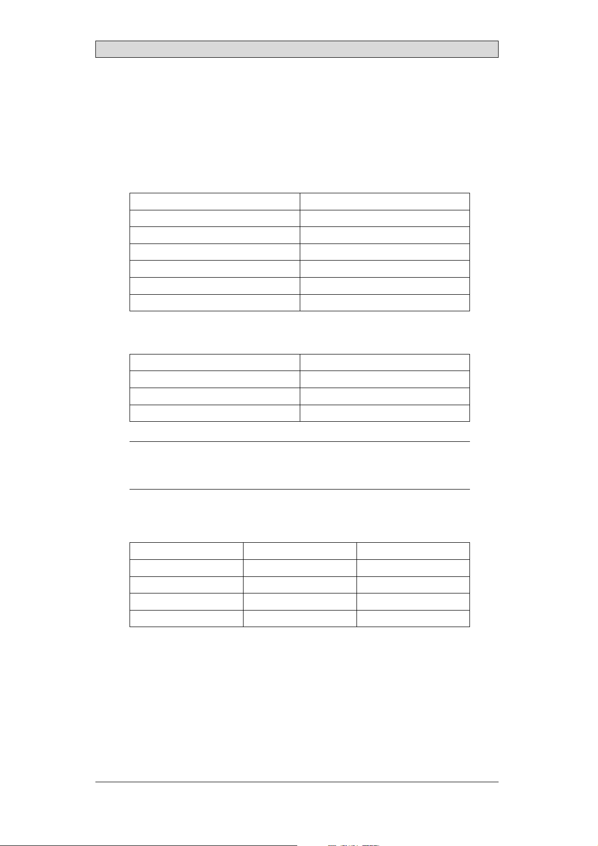
8.7 AvailableSparePartsforiXPanel T150
Ordernumber Description
601009278 COMPLETEFRONT
Includingfrontcover,touchoverlay,gasketsandlabels
601009041 DISPLAY
Includingframeandcable
601009049 BACKLIGHT
Includestwopieces, topandbo ttom
601009042 DISPLAYCABLE
321099040 POWERCONNECTOR
601009011 REARCOVER
601009003 CFCOVER
601009001 MOUNTINGBRACKETS
601009048 TOUCHPROTECTIONSHEET
601009270 FRONTLABEL
601009146 COMPLETEBOX
601009008 TESTPLUGETHERNET
EthernetRJ45testconnector
601009006 TESTPLUGRS232
RS232test connector
601009007 TESTPLUGRS422/485
RS422/485testconnector
601009004 TESTPLUGUSBH-D
USBHostandDevicetestconnector
601009069 TESTPLUGUSBH
USBHosttestconnector
BeijerElectronics, MAEN008
29
Page 30

Service Menu
9ServiceMenu
The service menu for the operator panel can be accessedbefore a project is
downloaded, or by setting the mode switches in mode 1000. The location of the
mode switches is described in the Mode Switches section.
9.1 ServiceMenuinanEmptyPanel
When no project is loaded in the panel memory, the panel will boot, displaying the
Welcome screen. Press anywhere on the panel display to enter the service menu.
9.2 ServiceMenuinaPanelwith Project
When a project is loaded inthe panel memory, the panel will automatically start to
execute the project. To display the service menu at boot-up:
1.
Disconnect the power supply from the panel.
2.
Set the mode switches in mode 1000 (Service Menumode).
3.
Connect the powersupply.
When the panel boots up it will suggest to go into the Touch Calibrate mode.
This ensures that it will be possible to recover from a bad calibration.
4.
Pressanywhere on the panel display to interrupt the timer and to enter the
service menu.
5.
Make desiredsettings in the service menu.
6.
Disconnect the power supply from the panel.
7.
Set themode switches in mode 0000 (Runmode).
8.
Reconnect the powersupply.
9.3 ServiceMenuOptions
The following options are available in the Service Menu:
9.3.1 IPSettings
Select to obtain an IP address automatically via DHCP, or specify an IP address.
The IP address can also be set during project transfer.
9.3.2 Date/Time
Use the Date/Time Settings dialog to set the time zone, date and time for the
panel.
BeijerElectronics, MAEN008
30
Page 31

Service Menu
9.3.3 EraseProject
The erase function will detect if the project is located in thepanel memor y or on a
memory card. Pressing Erase Project will completely remove the project and all its
components from the panel memory/the memory card.
9.3.4 FormatMemoryCard
The format memory card function will detect if external and internal memory
cards. Select which card to format and, in some cases, formatting alternatives.
9.3.5 TouchCalibrate
SelectTo uc h C al ib ra te if the touch screen needs to be calibrated. Followthe
instructions on the screen to perform a calibration.
BeijerElectronics, MAEN008
31
Page 32

Hardware Self T est
10 HardwareSelfTest
The self-test program canbe used to test aspects of operator panel functionality
and thecommunication ports. To run the testyou will need:
• Test plugs; see Te st pl u g d ra wi n g.
• 24 V DC, min. 3 A.
Followthe steps below to run the self-test program on the operator panel:
1.
Poweroff the operator panel.
2.
Go to the self-test. Set the modeswitches to the self-test positions, see the table
in the Mode Switches section.
3.
Power on the operator panel and follow the instructions at the bottom of the
display.
4.
When using the test plugs,make sure all LEDs on the 9-pin and 25-pin
D-subs are on.
5.
When the self-test is finished, power off the operator panel and set all mode
switches tothe OFF position.
If an error occurs during the self-test, try to fault trace. See Fault Traci
ng.
BeijerElectronics, MAEN008
32
Page 33

Additional InstallationTips
11 AdditionalInstallationTips
When experiencing communication problems in for example noisy environments
or when operating close to temperature limits, the following recommendations
are to be noticed.
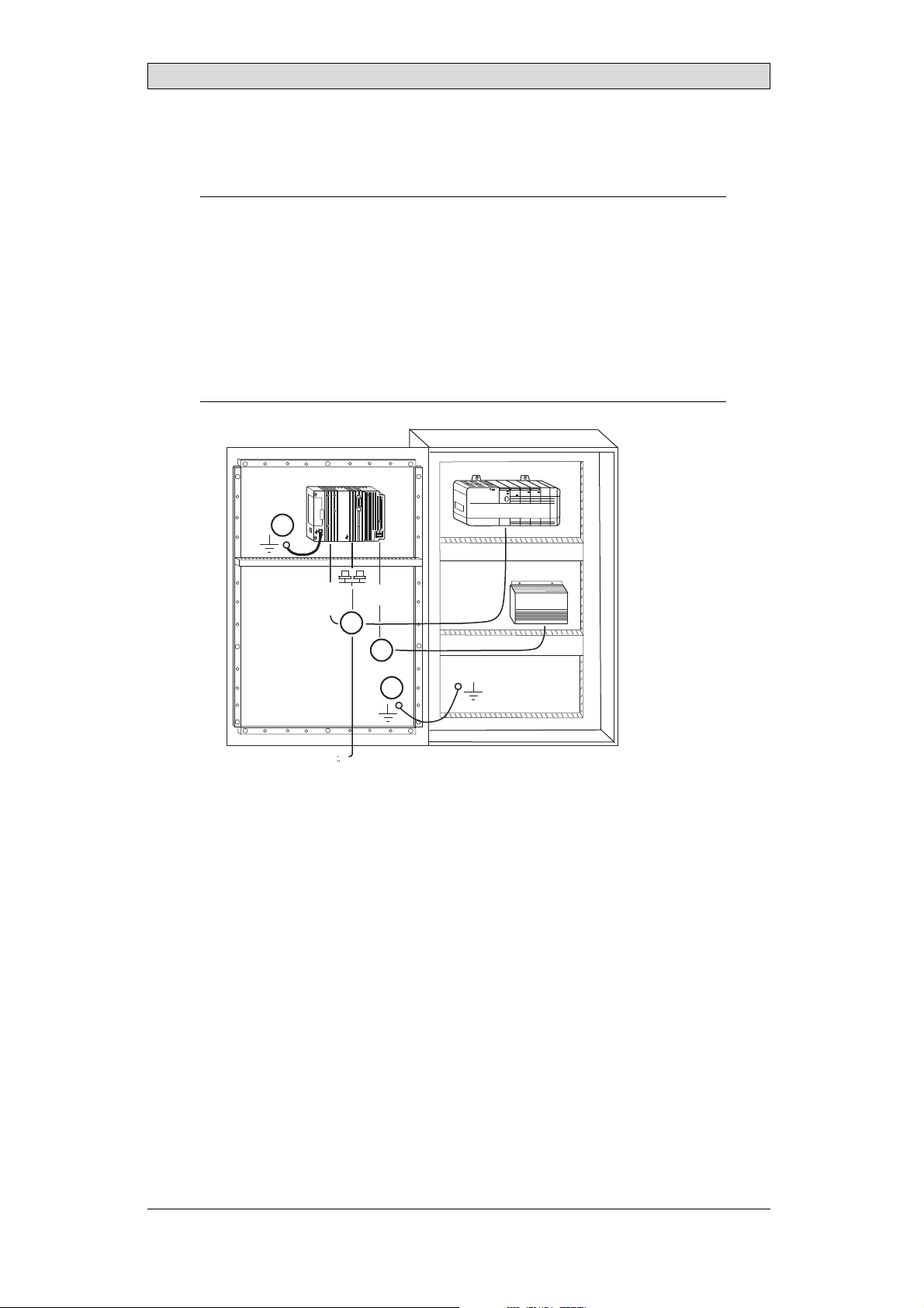
11.1 GroundingtheOperatorPanel
Door
Operator panel
1
Ferrite core
3
2
5
6
4
Mounting plate in the cabinet
Power supply
24 V DC
5350
The operator panel’s mounting clamps do not provide a secure grounding
connection between the paneland the device cabinet, see 1 in drawing above.
1.
Connect a 2.5 mm
and the panel chassis, see 2 in drawi
2.
Connect a 6 or 4 mm
2
wire between theope
rator panel’s quick-connect plinth
ng above.
2
wire or grounding braid between the panel’schassis and
the closest grounding point on the door, see 3 in drawing above.
3.
Connect a strong but short grounding braid between the door and the device
cabinet,see 4 in drawing above.
4.
Twist the cables onto the 24V DC feed, see 5 in drawing above.
2 turns around the ferritecore provide 4 times the suppression of 1 turn.
3 turns around the ferritecore provide 9 times the suppression of 1 turn.
A ferrite core suppresses disturbances to the 24 V feed, see 6 in drawing above.
Note:
Thegroundingwiresshouldbeshortandtheconductorshould havealargearea.
Along, thingroundingwirehasa veryhighimpedance(resistance)athighfrequencies
andwill notguidedisturbancestotheground.
Multi-wireconductors arebetterthansinglewireconductorswiththesamearea.
Abraidedconductorwirewiththe sameareaiseven better. Thebestis ashort,thick
groundingbraid.
BeijerElectronics, MAEN008
33
Page 34

Additional InstallationTips
11.2 EthernetConnectioninthePanel
Industrial Ethernet
RJ45
RJ45
RJ45
RJ45
Operator panel
RJ45
1
2
Operator panel
RJ45
Operator panel
RJ45
Operator panel
RJ45
5351
Shielded
0.1 uF
250 V
3
4
1-1
2-2
3-3
8-8
Short and
unshielded
5
In some industrial units for Ethernet,the RJ45 contact’sshield is connected to the
chassis via a capacitor, see 1 in drawing above.
The operator panel’s Ethernet shield is directly
connected to the chassis, see 2 in
drawing above.
1.
Check whether the other Ethernet unit has its shield directlygrounded or
grounded via a capacitor.
Note:
Inmany cases,connectingtheshieldedEthernetcablingtothechassisatbothendsis
inappropriate. Humor groundingloopscanoccur. Unshieldedcablingmayeven result
infewercommunicationerrors.
A good solution may be to use a shielded Ethernet cable, but to connect the shield
at one end only.
One option is to break the shield, see 3 in drawing above.
A more elegant method is to expand the shielded Ethernetcabling with a piece of
unshielded Ethernet cable, see 4 in drawing above.
You can ground the shield via an external 0.1 uF/250 V plastic capacitor,see 5 in
drawing above. This will connect the HF transients to the ground.
BeijerElectronics, MAEN008
34
Page 35

Additional InstallationTips
11.3 ToAchieveBetterEMCProtection
• Initially,use the original cabling from Beijer Electronics primarily.
• Use shielded cables for RS232 communication.
• Use twisted pair and shielded cabling for RS422 and RS485.
• Use the cabling intended for the bus type; Ethernet, Profibus,CC-Link,
CAN, Device Netetc.
• Install and connect according to applicable specifications for the relevant bus
standard.
• Use shielded cabling for Ethernet,preferably with foil + braided shield.
• D-sub covers should be shielded, and the shield should be connected to the
cover 360 ° w here the cable comes in.
• Connect the shield at both ends.
Shielded cable
0.1 uF/250 V
Ground plane 1 Ground plane 2
Ground plate Ground plate
Not same potential
in another building
5352
With longer distances, there is a risk that the ground potential may be different.
In that case, the shield should only be connected at one end. A good alternative
is to connect the other end of the shield to the ground via a 0.1uF/250 V plastic
capacitor. Both ends are then connected to the ground in terms of HF, but only
connected to the ground at oneend in terms of LF, thus avoiding the 50 Hz
grounding loops.
Metal cabinet Metal cabinet
Terminal or connector Terminal or connector
Cable clamp
in steel
Short distance
EMC cable gland Plastic cable gland
Shielded cable Shielded cable
1.
Usean EMC cable gland or regular plastic cable gland, remove the outer jacket
5353
and connect the shield to the installation plate with a 360 ° metal cable clamp.
2.
Place the 24 V DC and communications cabling in one cable trunk/cable duct
and 230/380 V AC in another. If the cables need to be crossed, cross them at
90 ° only. Avoidcombining the cabling for stronger 24 V DC outputs with
the communication cabling.
Ferritecores that are snapped onto theshielded cabling may remove minor
disturbances. Large ferrite pieces that are snappedonto unshielded cabling and
where the wires go 2-4 times around the cores are approximately 5-25 times more
efficient.
BeijerElectronics, MAEN008
35
Page 36

Additional InstallationTips
11.4 AmbientTemperature
The maximum ambient temperature for the operatorpanel is provided in the
specifications. The ambient temperature refers to the temperature in the device
cabinet which cools the panel’s electronics.
Top
50 °C inside
Operator
panel
30 °C outside
Middle
45 °C inside
Bottom
40 °C inside
Power
Power
Power
Axial fan
120 x 120 mm
Airflow
5354
Inmostcases,theambienttemperaturefortheoperatorpanelissignificantly
higher than the devicecabinet’sambient temperature.
If the cabinet is tall and there are a number of hea
temperature at the top of the cabinet will be con
theoretical temperature increase that would
sensitivetoheat. Thelifespanofanelectro
° increase in temperature. A 15-20 ° tempera
t-generating devices,the
siderably higher than the
be expected. All electronics are
lytic capacitor is cut in halfwith an 8-10
ture increase results in a quarter of the
lifespan etc.
Rittal has a good program for estimatingthe anticipated average temperature in
the cabinet as well as a large program for controlling the temperature in the device
cabinet.
An enamel-coated steel cabinethas
a radiant heat value of 5.5 W/m
2
and degrees
C.
Installing a fan inside the cabinetwill even out the temperature, while moving air
provides considerably better cooling than still air. A suitable fan is a 120 x 120 mm
axial fan, available in 24 V DC, 115 and 230 V AC.
Installthefansothatitsit
operator panel. If the fan i
ambient temperature will
s in the cooler areaand will blow cold air against the
s mounted at the top and sucksair upwards, the fan’s
be higher = shorter lifespan.
Agoodfanwithaball-bearingmountinghasanexpectedlifespanofatleast
40,000 hours (not a guaranteedlifespan) at 40 °C. This corresponds to at least 4
years of continuous use. If a thermostat is installed, the fan only needs to come
on when needed.
Large graphic termi
lighting is off. Th
nals draw only one fifth of the current when the background
e loss effect drops from e.g. 25 W to only 5 W.
The operator panel’s loss effect = supply voltage x current. Virtually no power goes
to external users and no loss effects due to inputs.
BeijerElectronics, MAEN008
36
Page 37

11.5 Safety
Most of the operator panels are fed with 24 V DC.
Power supply
1
2
3
230 V AC to 24 V DC
Power supply
230 V AC to 24 V DC
Power supply
230 V AC to 24 V DC
230 V AC
+24 V
0 V
4
+24 V
0 V
4
Distance?
+24 V
0 V
4
Operator panel
Operator panel
Operator panel
Small controller with expansion unit
COM1
COM100
Ch0
Ch1
Ch100
Ch101
5355
Additional InstallationTips
Ifyouuseapowersupplythatmeetssafetystandardsandonlyfeedstheoperator
panel, there is no problem. See 1 in drawing above.
However,ifyouhavea24Vunitthatalsofeedsotherunits,thereisreasontobe
cautious, see 2 in drawing above. The operator panel does not have insulation that
meets safety requirementsin the event of a potential short circuit between230 V
AC and 24 V DC. Itis assumed that the 24 V feed is secure, for example, SELV
according to EN 60950 (protection against electric shock) and UL 950.
Example:
Hereis anexamplethatexplainswhyasecure24 VDCfeedcanberuinedbymixing24
Vrelaycontactswith230VACrelaycontactsinasmallercontroller. Checkthatthe
“clearancesand creepagedistancesbetween24V DCand230VAC fulfillEN60950orUL
950”. Ifnot, inputaseparate24Vunitintotheoperatorpanel.
If there is a substant
AC, it is OK to use the
ial distance between the relay contacts for 24 V DC and 230 V
same 24 V devices for allfeeds. See 3 in drawing above.
Connect 0 V on the 24 V feed to the ground, see 4 in drawing above. This offers
three advantages:
• Safety is increa
connection or s
• Tr a n si e nt s o n
• No risk that th
is not unusua
sed. The24Vfeedwillnotbeliveintheeventofafaulty
hortcircuitbetween0V(24V)and230Vphase.
the 24 V feed are connected to the ground.
e 24 V feed is at a high level in relationship to the ground. This
l since there is high static electricity.
BeijerElectronics, MAEN008
37
Page 38

11.6 GalvanicIsolation
r
Additional InstallationTips
+24 V DC
DC/DC
galvanic isolation
Filter
0 V
1.5 m
Internal electronic
VCC
0 V (GND)
RS232RS422/485
USB
USB
DC/AC
Ethernet
CFL
5356
The operator panel has galvanicisolation against the 24 V DC feed but no galvanic
isolation between the communication ports for RS232, RS422/485and USB.
Only the Ethernetconnection has galvanic isolation.
Operator panel Modular controller Printe
RS422 RS232 USB
**
* *
Not same ground potential
* = Internal 0 V (GND) connection
When a PC is connected to the panel, the panel’s internal 0 V (G
*
Power CPU COM COM2
***
*
PCPC
5357
ND) will be
connected to the protective ground via the PC.
A number of USB devices can have the shield connected together with the
protective ground. Here, the panel’s 0 V (GND) is connected to the protective
ground when, for example, a USB memory stick, keyboard or similar device is
plugged in.
If a number of units areconnected that have a 0 V a
these are connected to various grounding poin
problems. Grounding currents go through com
of the controller, and internally in th
e operator panel, and can cause errors.
nd a ground connection, and
ts, there is a substantial risk of
munication cables, the rear plate
Use external units to improve communication and achieve galvanicisolation.
Westermo has good industry-standard insulators that are also insulated fromthe
24 V DC feed.
Note:
Itis veryimportanttomakesurethatthe24Vfeedintheexternalinsulationunitisnot
connectedtooneofthecommunication outlets. Ifitdoesnothave100%insulation
againstthe 24Vfeed,disturbancesandgroundingcurrentsfromthe0Vonthe24V
sidewi ll disruptcommunication.
Usingthis typeofunitsolveso ne problembutcreates alargerproblem! Asubstandard
installationmayworknow,butproblemsmayarisewhenotherdevicesareconnected.
BeijerElectronics, MAEN008
38
Page 39

Additional InstallationTips
11.7 CableandBusTerminationRS485
• Use shielded and twisted pair cable. The pair capacitance may not exceed 52.5
2
pF/m and area at least 0.25 mm
(AWG 24), if you want to use the maximum
transfer distance and maximum transfer speed.
• 0 V, the reference voltage for communication should be included in
the cabling. With two-way communication use two pairs; one pair for
communication and one pair for 0 V.
• The shield must be grounded at one end. The other end is usually grounded,
but with longer distances or when thereis a difference in the ground potential,
theshieldshouldbeconnectedtothegroundvia0.1uF/250Vplastic
capacitor to preventground current in the braidedshield. A number of
manufacturers recommendthat the shield be grounded at each node. Various
manufacturers have different systems for bus termination. The RS485
standard does not describe howthe “Fail Safe”function would be carried out,
justthatthesystemshouldbeabletohandletheerror.
Depending on the recipients’ design, the bus wires may be on the same level or
require pull-up orpull-down to ensure that no faulty signals are detected when the
bus is in resting mode (all transmitters are disconnected).
Inside operator panel
+5 V
0 V
1 23
1 K
120 ohm 120 ohm
1 K
+5 V
(120 ohm)
14
1 K
2
15
6
19
1 K
7
8
0 V
0 V
4
55
17
50
Operator
panel
RS422
1 2 3 4 5 6 7 8
CAB8CAB8 Bus
2
15
3
16
17
4
14
+5 V
VCC
8
0 V
7
0 V
VCC
1 K
120 ohm
1 K
RS485
1
2
3
4
5
6
Shield
7
8
Bus termination
0 V
0 V
5358
Some (older) operator panels had pull-up and pull-downresistance except for
the actual bus termination at 120 ohm, similar to Westermo and Profibus. See 1
in drawing above.
Newer panels haveanother type of recipient, so-called built-in “Fail Safe”,where
simple bus termination resistance is sufficient. See 2 in drawing above.
If other nodes on the RS485 network requirepull-up and pull-down and the
operator panel is at one end of the loop, one of the following procedures can be
carried out:
• Connect two 1k/0.25 W resistors in the 25-pole D-subcontact. See 3 in
drawing above. Set jumper pins 6-19.
• Use CAB8. It offers the option of bus termination with pull-up/-down. It
isalsoeasytoconnectthebuscableviathescrewterminalblock. See4in
drawing above.
BeijerElectronics, MAEN008
39
Page 40

Fault Tracing
12 FaultTracing
This section includes differentfault scenarios and steps to follow to trace the fault.
TheiXPanelT150isnot workingproperly,andthe
powerLEDisoff
1.
Isthepowervoltagecorrect?
2.
Does the power supply de liver enough current?
3.
Check the fuse.
4.
Check the power card.
5.
Is the power card correctly mounted?
TheiXPanelT150isnotcommunicatingwiththe
controller
1.
Check the communication cable between the units.
2.
Check that the operator panel has a controller driver downloaded.
3.
Checkthatthecorrectcontrollerdriverisused.
4.
Check the communication ports on the CPU board.
TheiXPanelT150isworkingbutthebacklightisoff
1.
Check the backlight dimming.
2.
Check that the backlight is connected to the power card.
3.
Replace the backlight according to the Replacing th
4.
Check the DC/AC on the power card.
eBacklightsection.
TheiXPanelT150isnotworking,thebacklightisoff
butthepowerLEDison
1.
Check the backlight dimming.
2.
Check the CPU boardfor burned components.
3.
Download new firmwareto the operato
rpanel.
TheiXPanelT150doesnotincludethelatest
firmware
1.
Check the versions included with the operator panel.
2.
Make sure to savea copy of the project to the PC.
3.
Download an updated image wi
th the Image Loader and follow the directions.
BeijerElectronics, MAEN008
40
Page 41

Fault Tracing
TheiXPanelT150isworking,butoneormorekeys
arenotworking
1.
Check that the flex cables are correctly fitted.
2.
Replace the front according to the Replacing the Rear Cover section.
Thetouchscreenismalfunctioningorisnot
respondingatall
1.
Re-calibrate the touch screen according to the Calibrating the Touch Screen sec-
tion.
2.
Check that the flex cable is correctly fitted.
3.
Replace the display of theoperator panel according to the
Replacing the Display/Display Cable section.
4.
Check the touch interface on the power card.
Linesindisplayhaswrongcolororthedisplaypicture
isshifted
1.
Check if the display has a wide vertical or horizontal area across the
display. It should be at least 2-3 cm wide with a grey or black color. See
Replacing the Display/Display Cable for instructions on how to correct this.
2.
Make sure the display cable is correctly fitted.
3.
Make sure the display cable is not folded or damaged in any way. Replace the
display cable accordingto the Replacing the Display/Display Cable section.
Lowbattery/Nobattery
1.
Connect iX PanelT150 to an external power source to automatically charge
the battery.
BeijerElectronics, MAEN008
41
Page 42

Software
13 Software
This chapter describes how to maintain and update the software in the iX Panels.
The chapter includes a general description of theoperator panel software and
instructions about how to upgrade the softwarean d load projects and system
programs.
13.1 GeneralInformationabout Software
The software requiredto run and maintain the operator panels is found on the
software USB stick. It is also availablethrough your local distributor.
The software is testedby the manufacturer’s own testing department before
market introduction is approved. The test procedure is closely integrated with the
development process. The test group works in close concert with the developers
andisISEBCertifiedforSoftwareTesting.
13.1.1 SoftwareProducts
The following softwareproducts are used:
• iX Developer
iX Developer is used for creating application projects for iX Panels and their
accessories.
• Remote AccessViewer
Remote AccessViewer is a program for remote ac
It is possible to access, reflectand control t
client program Remote Access Viewer (freew
server (Remote Accessfunction) in th
• System Program
The iX PanelT150 is delivered with a systemprogram (operating system)
pre-stored in the operator panel memory.
The firmware (the software in the operator panel) consists of three parts at
delivery:
1. E-Boot, the program that starts up the operator panel and WindowsCE.
2. Windows CE .net 4.20, the operating system for the operator panel.
3. OPsys, the system program in the operator panel that contains the HMI
functionality.
eiXPanels.
cess and control of theiX Panels.
he iX Panelsfrom a PC using the VNC
are) together with the built-in VNC
BeijerElectronics, MAEN008
42
Page 43

13.2 UpdateSoftware
When an update is available, an e-mail is sent to the distributors. The software is
also available on the manufacturer’s web site.
Theupdateshouldbeinstalledbyqualifiedpersonnel. Whenupdatingan
operator panel it is important to ensure that the power isn ot interrupted during
the transfer.
13.2.1 iXDeveloper
iX Developer isnot a freeware product.
A demo version can be downloaded from www.beijerelectronics.com.
To update iX Developer, an accredited iX Panelsdealer must be contacted.
13.2.2 RemoteAccessViewer
This software is included on the iX DeveloperUSB stick.
To update the Remote Access Viewer,go to www.beijerelectronics.comand select
Support/Downloads inthemenu. BrowsethesoftwarefoldertolocateRemote
Access Viewer. Run the .exe file and followthe instructions.
Software
13.2.3 SystemProgram
An upgrade of the complete software package is sometimes needed to t ake
advantage of new functionality. The completesoftwarepackageconsistsofthe
EBOOT, the WindowsCE operating system and the system program. The
upgradeisdonebyrunningtheImageLoader executable file, Bxxx_iml.exe. The
Image Loader application will h elp and guide you through the upgrade.
Usingthe Image Loader requires that the mode switches are set in mode 0100.
Whentheupgradeisfinished,theoperatorpanelwillreceivethedefaultIPaddress
192.168.1.1. Followthe instructions on the screen after startup to change the IP
address.
Note:
ALLexistingdata,includingt
operatorpanel willbedelete
Note:
TheImageLoadersoftwareisonlyintendedforcustomersandpartnersthathavean
operatorpanel. Nootherdistributionisallowed.
Requirements
hefile systemandtheprojectapplicationfiles,inthe
d(overwritten)bytheImageLoaderapplication.
Updating of the operator panel system program requires the following:
• A PC with Image Loaderapplication
• An Ethernet connection between the PC and the operator panel
• The operator panel IP address
• TheImagefilefromthewebsite
BeijerElectronics, MAEN008
43
Page 44

TransferImage
1.
Double-click on the executable Image Loader file to start the transfer program.
2.
Followthe instructions.
The image transfer procedure is completely menu-driven. The operator panel
will be ready for transfer directly after wards, provided that all steps are performed
and completed.
The following steps outlinethe transfer procedure:
1.
Disconnect the power supply from the panel.
2.
Set themode switches in mode 0100 (ImageLoad mode).
3.
Reconnect the powersupply.
4.
Select the operatorpanel to upgrade by entering its IP address.
5.
Click Upgrade.
6.
When the upgrade is finished, dis connect power from the operator panel.
7.
Set themode switches in mode 0000 (Runmode).
8.
Reconnect powerto the operator panel.
Software
Note:
Whenupdating anoperatorpanel,itis importanttoensurethatpower isnot
interruptedduring thetransfer.
Relatedinformation
ModeSwitches
BeijerElectronics, MAEN008
44
Page 45

Environmental Aspects
14 EnvironmentalAspects
This chapter includes information about the environmental impact of iX Panels.
More information can be found on the manufacturer’sweb site.
14.1 GeneralEnvironmentalAspects
The manufacturer’s activities meet internal requirementsas well as those of the
SS-EN ISO 9001:2000 and SS-EN ISO 14001:2004 international standards.
14.2 EnvironmentalImpactofthe OperatorPanels
14.2.1 MechanicalComponents
The aluminum and stainless steel used in the mechanical components arejudged
to be non-environmentally hazardous. The expanded rubber packing for the front
and the expanded polyethylene packing for the display contain an adhesive that is
not classified as environmentally hazardous.
Screws may have undergone the followingsurface treatments: Bright
nickel-plating or bright zinc-plating. Themembranekeyboardismadeof
polyester with silver wiring. On some models the keyboard contains LEDs.
Display frames andCF covers are made of halogen-free plastic, PC/ABS.
14.2.2 Electronics
CircuitBoard
Note:
AlloperatorpanelsareRoHScompliant.
The electronics are complex and almost all elements of the periodic table are
represented.
Display
There is a separate circuit board for the display. The liquid crystals in the display
are cyclohexanecompounds. The fluorescent tube containsmercury and lead
solder.
Batteries
The operator
classified a
(1997:645
panel contains a button cell lithium battery. The battery is not
s environmentally hazardous by the Swedish Battery Ordinance
).
BeijerElectronics, MAEN008
45
Page 46

Environmental Aspects
14.3 Recycling
The operator panels consist largely of aluminum. Itis a great advantage in terms of
both resources and the environment if it can be recycled. Make sure that operator
panels taken out of service are sent to facilities for electronic scrap.
The manufacturer’s electronic waste is recycled by Stena Technoworld AB.
Aluminum front/rearcasings and other coverscan be removed and recycled.
Plastic display frames and CF coversmust be recycled as hard plastic. The circuit
board contains many valuablemetals and should therefore be recycled.
Remove the lithium battery. Electrolytic capacitors and displays are currently not
classified as hazardouswaste, but may be harmful to health and the environment.
The electrolytic capacitors should be handled as per Handbook 2001:7 (NFS)
and displays as per NFS 2001:8.
Thefluorescenttubemustbehandledashazardouswaste.
The packaging ismade from wood fiber and shouldberecycled. Thelargeprinted
label on the front, however, must first be removed as it is made of PVC vinyl. The
label and the plasticbag for the brackets are recycledas soft plastic.
The manufacturer is a member of the REPA register. The protective filmon the
front is recycled as soft plastic. When the operator panel is no longer useful it
can be returned to the manufacturer for environmentally responsiblerecycling.
Contact the company for further information.
14.4 EnvironmentalImpactReport
An operator panel impacts the environment through its function, i.e., controlling
industrial equipment. The energy and the scrapped parts that can be saved with
efficient management mean that the operatorpanel contributes to reduced
environmental impact.
Listed below areexamples of how you can reduce environmental impact during
operator panel use.
• Switch thesystem off when not in use.
• Use green electricity.
• Use e nergy-saving options, e.g., turn off the backlight to both save energy and
reduce wearon the fluorescent tube.
• If possible, reduce the backlight brightness to reduceenergy consumption
and increase fluorescent tube service life.
Supplythe operator panel with 2
effect increases. Ensure that
recycled in an environmentall
4 V DC. If the input voltage is lower, the loss
the operator panel, battery, and packaging are
y responsible manner.
BeijerElectronics, MAEN008
46
Page 47

HEADOFFICE SUBSIDIARIES
SWEDEN GERMANY USA
BeijerElectronicsProducts AB Elektronik-SystemeLauer GmbH&Co. KG BeijerElectronicsInc.
Box426 Kelterstraße59 939N.PlumGroveRoad,Suite F
SE-20124Malmö,Sweden 72669Unterensingen, GERMANY Schaumburg,IL 60173,USA
Tel: +4640358600 Tel: +4970229660 0 Tel: +1847619 6068
Fax: +464093 2301 Fax: +4970229660 103 Fax: +1847619 6674
info@beijerelectronics.com info@lauer-hmi.com info.usa@beijerelectronics.com
TAIWAN CHINA
HitechElectronicsCorp. BeijerElectronics Co. Ltd
7&8F,No. 108Min-Quan Road Room201,Buildning B,No. 1618,
in-Tien,TaipeiShien, TAIWAN,R.O.C.231YishanRoad,Shanghai 201103,CHINA
Sh
Tel: +886-2-2218-3600 Tel: +862161450400
Fax: +886-2-2218-9547 Fax: +86216145 0499
info.hmi@hitech-lcd.com.tw info@beijerelectronics.cn
 Loading...