

Page 1
iXT12CInstallationGuide
1SafetyPrecautions
Both theinstaller and the owner and/oroperator of theoperator panel mustread
and understandthis installation manual.
1.1 General
Read the safetyprecautions carefully.
•
Check thedelivery for transportationdamage. If damage isfound, notify the
•
supplier as soon as possible.
Do not use the operator panel in an environment with high explosive hazards.
•
The supplier is not responsible for modified, altered or reconstructed
•
equipment.
Use only parts and accessories manufactured according to specifications of
•
the supplier.
Read the installation and operating instructions carefully before installing,
•
using or repairing the operator p anel.
Never allow fluids, metal filings or wiring debris to enter any openings in the
•
operator panel. Thismaycause fire or electrical shock.
Only qualified personnel may operate the operator panel.
•
Storingthe operator panel where the temperature is lower/higherthan
•
recommended in this manual can cause the LCD display liquid to
congeal/become isotopic.
The LCD display liquid contains a powerful irritant. Incaseof skin contact,
•
wash immediately with plenty of water. In case of eye contact, hold the eye
open, flush with plenty of water and get medical attention.
Thefiguresinthismanualservesanillustrativepurpose. Becauseofthemany
•
variables associated with any particular installation, the supplier cannot
assume responsibility for actual use based on the figures.
The supplier neither guarantees that the operator panel is suitablefor your
•
particular application, nor assumes responsibility for your product design,
installation or operation.
It is recommended to turn on and shut down the operator panel at least once
•
before installing any components/cards or before connecting the operator
panel to external devices, like for example serial devices.
1.2 DuringInstallation
The operator panel is designed for stationary installation on a plane surface,
•
where the following conditions are fulfilled:
– no high explosive risks
– no strong magnetic fields
– no direct sunlight
– no large, sudden temperature changes
Install the product according to the accompanying installation instructions.
•
Ground the product according to the accompanying installation instructions.
•
Only qualified personnel may install the operator panel.
•
Separate the high voltage, signal and supply cables.
•
Make sure that the voltage and polarity of the power source is correct before
•
connecting the product to the power outlet.
Peripheralequipmentmust be appropriate for the application and location.
•
1.3 DuringUse
Keep the operator panel clean.
•
Emergency stop and other safety functions may not be controlled from the
•
operator panel.
Do not use too much force or sharp objects when touching the keys,
•
touchscreen etc.
1.4 Serviceand Maintenance
Only qualified personnel should carry out repairs.
•
The agreed warranty applies.
•
Before carrying out any cleaning or maintenance operations, disconnect the
•
equipment from the electrical supply.
Clean the display and surrounding front cover with a soft cloth and mild
•
detergent.
Replacing the battery incorrectly may result in explosion. Onlyuse batteries
•
recommended by the supplier. During the warranty period, the battery needs
to be replaced by an authorized Beijer Electronics service center.
The unit can be reset by using the reset switch located behind the fan.
•
1.5 DismantlingandScrapping
The operator panel or parts thereof shall be recycled according to local
•
regulations.
The following components contain substances that might be hazardous
•
to health and the environment: lithium battery,electrolytic capacitor and
display.
1.6 AppearanceofAirinTouchScreen
The layer structure of the touch screencontains air and in rare cases
•
appearance of bubbles can arise. This is purely cosmetic and does not affect
any functionality of the panel. The appearance can occur under certain
environmental conditions such as temperature, h umidity, and atmospheric
pressure.
2Installation
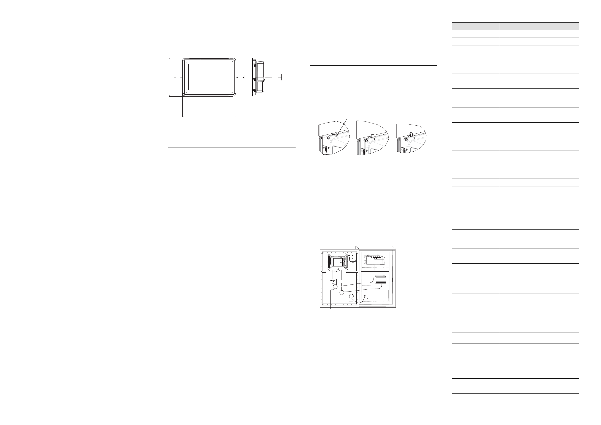
2.1 SpaceRequirements
Maximum installation plate thickness: 8 mm
•
Space requirements in millimeters when installing the operator panel:
•
100 mm
50 mm
242,2 mm
100 mm
340 mm
Note:
Thedimensionsonthedrawingarenotproportional.
Caution:
Theopeningsonthe enclosureareforairconvection. Donotcoverthese
openings.
50 mm
100 mm
2.2 Installation Process
The following is needed:
ATorxTX7screwdriver
•
1.
Unpackand check the delivery. If damage is found, notify the supplier.
Note:
Placetheoperatorpanel on astablesurfaceduring installation.
Droppingthepanelorlettingitfallmaycausedamage.
2.
Use the cut out dimensions that are included on the outline drawing, found
in section Operator Panel Drawings and in the Technical Data table, to cut a
correct opening in the cabinet. A separate cut out drawing is available for
download from the Beijer Electronics web site.
3.
Secure the operator panel in position by screwing the M4 Torx screw,allowing
the built-in bracket to tighten against the panel:
M4 x 20.7
0.4 Nm
4.
Connect the cables in the specified order,accordingto the drawing and steps
below.
Caution:
Ensurethattheoperatorpanelandthecontrollersystemhavethesame
•
electricalgrounding(referencevoltage level), otherwise errors in
communicationmayoccur.
Theoperatorpanelmustbebroughttoambienttemperaturebefore it
•
isstartedup. Ifcondensationforms, ensurethattheoperatorpanelis
drybeforeconnecting it to the power outlet.
Ensurethatthevoltageandpolarityofthepowersourceiscorrect.
•
Useonlyshieldedcommunicationcables.
•
Separatehighvoltage cablesfromsignalandsupply cables.
•
B
RS232/
RS422/
RS485
24V DC
C
D
A
Ethernet
– Connect cable A.
– Connect cable B, using an M5 screw and a grounding conductor (as
short as possible) with a cross-section of minimum 2.5 mm
– Connect cable C.
– Connect cable D. The recommended cross-section of the cable is
5.
Carefully removethe laminated film over the operator panel display, to avoid
2.5 mm
2
.
Power
Controller
24V DC
2
.
static electricity that coulddamage the panel.
2.2.1 ConnectionstotheController
Forinformationabout the cables to be used when connecting the operator panel to
the controller,please refer to the help file for the driver in question.
2.2.2 OtherConnectionsandPeripherals
Cables, peripheral equipment and accessories must be suitable for the application
and its environment. Forfurtherdetailsor recommendations, please refer to the
supplier.
3TechnicalData
Parameter iX T12C
Frontpanel,W×H×D
Cutoutdimensions,W × H
Mountingdepth 72mm(172 mm includingclearance)
Standalonemounting
Frontpanelseal
Rearpanel seal
Touchscreenmaterial Polyesteronglass,resistive.
Touchscreenoperations 1million fingertouchoperations
Reversesidematerial Powder-coatedaluminum
Framematerial Powder-coated aluminum
Weight 4.2kg
Serialportfor
COM1RS232and
COM2RS422/RS485
Serialportfor
COM3RS232and
COM4RS422/RS485
Ethernet 2×10/100/1000Base-T(shieldedRJ45)
USB 4×USBHost2.0, max outputcurrent500mA
Processor
Externalstoragemedia
MemoryRAM 2GB*/4GB*DDR-3SO-DIMM1333MHz
LED
Realtime clock Yes(onchip)
Battery
Powerconsumptionat
ratedvoltage
Fuse
Powersupply
Display TFT-LCDwithLED backlight. 1280×800pix-
VGA
DVI
Activeareaof display,
W×H
Operatingtemperature 0°C–+50°C
Storagetemperature -20 °C –+70°C
340×242×79mm
324×226mm
VESA100×100
Note: Maximumscrewlength for VESA
mountingis5.5mm. Usageof longerscrews
mayleadtodamage.
IP65
IP20
(1)
Overlay: AutotexF157 orF207
9-pinD-subcontactwithRS232RTS/CTS,
chassis-mountedfemalewithstandard
lockingscrews4-40UNC
Note: RS422 Interfaceisnotavailableyet.
9-pinD-subcontactwithRS232RTS/CTS,
chassis-mountedfemalewithstandard
lockingscrews4-40UNC
Note: RS422 Interfaceisnotavailableyet.
Intel®Celeron®B810E(2×1.6GHz),
2MBL2Cache,Intel® QM67Chipset
Optional: Intel® Core™i32310E
(2×2.1GHz)(Hyperthreading),
3MBL2Cache,QM67Chipset
Optional: Intel® Core™i72715QE(4×2.1
GHz)(Turbo2.0,Hyperthreading),
6MBL2Cache,QM67Chipset
*forexactconfigurationpleaseseepricelist
viaUSB
*dependingonProcessorModule
1×multi-color
LithiumbatterytypeBR2032(orCR2032),
exchangeable
107W
10A
DCinputrange: 18-32VDC(140W)ATX
standard
CE:Thepowersupply must conformwiththe
requirementsaccordingtoIEC60950and
IEC61558-2-4.
ULandcUL:Thepower supply must conform
withtherequirementsforclass II power
supplies.
els,16.7millioncolors
1×VGA:resolutionmax. 2048× 1536@75Hz
1×DVI-D singleLink: Resolutionmax.
1600×1200or1920×1200(withreduced
blanking)
261.12×163.2mm
.
Page 2

Parameter
Relativehumidity 5-85%non-condensed
Approvalsand
certifications
(1)
SeesectionChemicalResistanceformoreinformation.
Informationisavailableonthewebsite
www.beijerelectronics.com
iXT12C
4 ChemicalResistance
4.1 MetalCasing
The frame and casing material is powder-coated aluminum. Thispowder paint
withstands exposure to the following chemicals without visible change:
Aceticacid10% Phosphoric a cid 4%
Citricacid 10% Phosphoricacid10%
(1)
Seawater
Tap water
Turpentine
Phosphoricacid(<30%)
(<30%)
PureTurpentine
SBP60/95
Sulfuricacid (<10%)
(<50%)
(1)
Diesel
Distilledwater Sodiumchloride2%
Edibleoil Sodiumchloride20%
Fueloil Sulphuricacid20%
Hydrogenperoxide3%
The powder paint shows limited resistance to the following chemicals at room
temperature:
Butanol Nitricacid3%
Hydrochloricacid 5% Nitricacid 10%
Isopropylalcohol Phosphoricacid43%
Na-hypochlorite10%
Note:
Ifexposuretoanyofthe above chemicalsisdemanded,itisrecommended to
firsttestthechemicalinahiddenspotofthemetalcasing.
The powder paint shows little or no resistance to the following chemicals at room
temperature:
Aceticacid,conc. Methyl-ethylketone Toluene
Acetone
Ammonia5%
Ammonia,conc.
Ethylacetate Sodiumhydroxide30% 98octaneleadedpetrol
Nitricacid30% Trichlorethylene
Phenol Xylene
Sodiumhydroxide5% 97octane unleaded petrol
4.2 Touch ScreenandOverlay
4.2.1 AutotexF157/207
Autotex F157 or F207 covers the overlay surrounding the touch screen.
SolventResistance
Autotex F157/F207 withstands exposure of more than 24 hours duration under
DIN 42 115 Part 2 to the following chemicals without visible change:
Acetonitrile DieselDowney/
Ajax/Vimin
solution
Alkalicarbonate
(1)
solution
Ammonia(<40%)
Aceticacid(<50%)
Arielpowderin
solution
(1)
Bleach
Castoroil Methanol Trichloro acetic acid
Causticsoda
(1)
(<40%)
(1)
(1)
(1)
Lenor
Ethanol Potassiumferricyanide
Glycerine Potassiumhydroxide
Glycol
Gumption
Hydrochloricacid
(<36%)
Linseedoil Tomatoketchup
Nitricacid(<10%) White Spirit
Cuttingoil Paraffinoil Windex
Cyclohexanol Persilpowderin
Diacetonealcohol Petroleumspirit
(1)
Extremelyfaintglossingofthetexture was noted.
solution
(1)
(1)
(1)
Wisk
-
Autotex withstands DIN 42 115 Part 2 exposure of up to 1 hour duration to glacial
acetic acid without visiblechange.
Autotex is not resistant to high pressure steam at over 100 °C or the following
chemicals:
Concentratedmineralacids Benzylalcohol
Concentratedcausticsolution Methylenechloride
4.2.2 Touch ScreenSurface
The touch screen surface on the operator panel withstands exposure to the following
solvents without visible change:
Solvents
Acetone 10minutes
Isopropanol
Toluene 5hours
Time
10minutes
4.2.3 Autotex
It is recommended to use the AutoflexEBA 180Ltouch display protection film, that
can be ordered from Beijer Electronics.
SolventResistance
Autoflex EBA 180L withstands exposure to the same chemicals as Autotex F157 or
F207 according to section Autotex F157/207.
OutdoorUse
In common with all polyester based films, Autoflex EBA 180L is not suitable for use
in conditions of long-term exposure to direct sunlight.
5 OperatorPanelDrawings
5.1 Connectors
12345678 9
Pos. Connector Description
1DVI
2VGA
3 COM 3/4 Communication Ports
4
COM1/2 CommunicationPorts
5
LANPortB
6LANPortA
7
USB 2×USBHost2.0,maxoutputcurrent500mA
8 USB 2×USBHost2.0,maxoutputcurrent500mA
9
Powersupply
Externalmonitor
Externalmonitor
1×10/100/1000 Base-T(shieldedRJ-45);Intel
82574
1×10/100/1000Base-T (shieldedRJ-45);
Intel82559
DCinputrange: 18-32VDC (140W)ATX
standard
5.2 CommunicationPorts
Pin
Note: RS422 Interface is notavailableyet.
Note:
Inordertoutilizetwocommunicationportsonthesamephysicalport,the
Y-splitcableCAB109mustbeused.
DrawingforexternalcableCAB109(drawing#Z7100-029E) is availableonthe
website: www.beijerelectronics.com
Serialport,9-pin female Serialport,9-pin female
COM1 COM2 COM3 COM4
1
2RS232RxD
3 RS232TxD
4
5 GND GND GND GND
6
7
8RS232CTS
9
-
-
-
RS232RTS
-
RS422Tx+
RS485Tx+/Rx+
-
-
RS422Rx+
RS422Tx-
RS485Tx-/Rx-
--
--
RS422Rx-
-
RS232RxD
RS232TxD
-
-
-
RS422Tx+
RS485Tx+/Rx+
-
-
RS422Rx+
RS422Tx-
RS485Tx-/Rx-
RS422RTS+
RS422RTS-
RS422Rx-
5.3 iXT12COutline
242
340
7
max. 8 mm
Note:
AStepCADfile isavailable ontheweb sitewww.beijerelectronics.com
72
224 99
32299
Order no: MAEN082D
Copyright © 2013-09 Beijer Electronics. Allrights reserved.
The information in this document is subject to change without notice and is
providedas available at the time of printing. BeijerElectronics AB, including
all its group companies, reserves the right to change any information without
updating this publication. Beijer Electronics AB, including allits group
companies, assumes no responsibility for any errors that may appear in this
document. Readthe entire installation manual prior to installing and using
this equipment. Onlyqualifiedpersonnel may install, operate or repair this
equipment. BeijerElectronics AB, including all its group companies, are
not responsible for modified, altered or renovated equipment. Because the
equipment has a wide range of applications, users must acquire the appropriate
knowledge to use the equipmentproperly in their specific applications. Persons
responsible for the application and the equipment must themselves ensure that
each application is in compliance with all relevant requirements, standards and
legislation in respect to configuration and safety. Only parts and accessories
manufactured according to specifications set by Beijer Electronics AB, including
all its group companies, may be used.
BEIJER ELECTRONICS AB, INCLUDING ALL ITS GROUP
COMPANIES,SHALL NOT BE LIABLE TO ANYONE FOR ANY
DIRECT,INDIRECT,SPECIAL, INCIDENTALORCONSEQUENTIAL
DAMAGES RESULTING FROM THE INSTALLATION, USE OR REPAIR
OF THIS EQUIPMENT,WHETHER ARISING IN TORT, C ONTRACT,
OR OTHERWISE. BUYER'S SOLE REMEDY SHALL BE THE REPAIR,
REPLACEMENT, OR REFUND OF PURCHASE PRICE, AND THE
CHOICE OF THE APPLICABLE REMEDY SHALL BE ATTHE SOLE
DISCRETION OF BEIJER ELECTRONICS AB, INCLUDING ALL ITS
GROUPCOMPANIES.
Headoffice
BeijerElectronicsAB
Box426
20124Malmö,Sweden
www.beijerelectronics.com/+4640358600
 Loading...