

Page 1

MAEN993, 2009-12
SCOM Protocol on RBC
Manual
English
Page 2

Foreword
SCOM Protocol on RBC
Foreword
The Lauer SCOM Protocol is designed for controlling different Beijer Electronics
devices remotely over different kind of interfaces. It is based on the SCOM Protocol,
allowing easy replacement of existing units. Besides the standard command set, the
Lauer SCOM Protocol includes a rich set of special purpose commands for extended
remote controlling options. The SCOM Protocol is extended with these special features, without affecting the compatibility.
Some of the major extensions are:
• Special purpose command set available with the new SCOM command “LAU”.
• Extended address field functionality, which enables device grouping, allowing a total count of 240 devices in a network (15 groups, 16 devices in each group).
© Beijer Electronics AB, MAEN993, 2009-12
All examples in the manual are intended solely to increase understanding of the software’s functionality and
use. Beijer Electronics AB bears no responsibility if these examples are used in actual applications.
Because of the large number of application areas for this software, users must acquire the appropriate knowledge to use the software properly for their specific applications. Persons responsible for the application must
themselves ensure that each application is in compliance with all relevant requirements, standards and legislation in respect to configuration and safety.
Beijer Electronics AB assumes no responsibility for damages that may occur during installation or use of the
software.
Beijer Electronics AB hereby forbids all modification of the software.
Beijer Electronics, MAEN993
Page 3

Contents
1 Interface Configuration 5
2 Message Format and Description 6
3 Device Addressing 8
4 Protocol Description and Timings 9
5 Command Reference 13
Contents
5.1 BRT . . . . . . . . . . . . . . . . . . . . . . . . . . . . . . . . . . . . . . . . . . . . . . . . . . 14
5.2 MAN . . . . . . . . . . . . . . . . . . . . . . . . . . . . . . . . . . . . . . . . . . . . . . . . . 16
5.3 VER . . . . . . . . . . . . . . . . . . . . . . . . . . . . . . . . . . . . . . . . . . . . . . . . . . 17
5.4 POT . . . . . . . . . . . . . . . . . . . . . . . . . . . . . . . . . . . . . . . . . . . . . . . . . . 18
5.5 TYP . . . . . . . . . . . . . . . . . . . . . . . . . . . . . . . . . . . . . . . . . . . . . . . . . . 20
5.6 LAU . . . . . . . . . . . . . . . . . . . . . . . . . . . . . . . . . . . . . . . . . . . . . . . . . . 21
5.6.1 LAU_CONFIG_GETFWVERSION (0x0101). . . . . . . . . . . . . . . . 23
5.6.2 LAU_CONFIG_GETMANUFACTURER (0x010C) . . . . . . . . . . 24
5.6.3 LAU_CONFIG_GETDEVICENAME (0x010D) . . . . . . . . . . . . . 25
5.6.4 LAU_CONFIG_GETDILMODE (0x010E) . . . . . . . . . . . . . . . . . 26
5.6.5 LAU_CONFIG_GETDISPLAYADR (0x010F) . . . . . . . . . . . . . . . 27
5.6.6 LAU_CONFIG_GETCOMSERMODE (0x0110). . . . . . . . . . . . . 28
5.6.7 LAU_CONFIG_GETPOTMODE (0x0113) . . . . . . . . . . . . . . . . . 29
5.6.8 LAU_CONFIG_GETREMOTECONTROL (0x011C). . . . . . . . . 30
5.6.9 LAU_CONFIG_GETSTARTUPBRIGHTNESSMODE (0x0124) 31
5.6.10 LAU_CONFIG_GETSERIALNUMBER (0x0125) . . . . . . . . . . . . 33
5.6.11 LAU_CONFIG_GETDEFAULTBRIGHTNESS (0x0126) . . . . . . 34
5.6.12 LAU_CONFIG_GETDISPLAYGROUP (0x0127) . . . . . . . . . . . . 35
5.6.13 LAU_CONFIG_GETKEYPRESSMODE (0x012A). . . . . . . . . . . . 36
5.6.14 LAU_CONFIG_SETDILMODE (0x018E) . . . . . . . . . . . . . . . . . . 38
5.6.15 LAU_CONFIG_SETDISPLAYADR (0x018F). . . . . . . . . . . . . . . . 40
5.6.16 LAU_CONFIG_SETCOMSERMODE (0x0110) . . . . . . . . . . . . . 42
5.6.17 LAU_CONFIG_SETREMOTECONTROL (0x019C) . . . . . . . . . 44
5.6.18 LAU_CONFIG_SETSTARTUPBRIGHTNESS MODE (0x01A4) 46
5.6.19 LAU_CONFIG_SETSERIALNUMBER (0x01A5) . . . . . . . . . . . . 48
5.6.20 LAU_CONFIG_SETDEFAULTBRIGHTNESS (0x01A6) . . . . . . 49
5.6.21 LAU_CONFIG_SETDISPLAYGROUP (0x01A7). . . . . . . . . . . . . 51
5.6.22 LAU_CONFIG_SETKEYPRESSMODE (0x01AA) . . . . . . . . . . . . 53
5.6.23 LAU_CONTROL_BUZZER (0x0202) . . . . . . . . . . . . . . . . . . . . . 55
5.6.24 LAU_CONTROL_RESET (0x0207) . . . . . . . . . . . . . . . . . . . . . . . 57
5.6.25 LAU_STATUS_DISPLAYADR (0x0302). . . . . . . . . . . . . . . . . . . . 58
5.6.26 LAU_STATUS_SCOMSERMODE (0x0303) . . . . . . . . . . . . . . . . 59
Beijer Electronics, MAEN993 I
Page 4

Contents
5.6.27 LAU_STATUS_POTMODE (0x0304) . . . . . . . . . . . . . . . . . . . . . .61
5.6.28 LAU_STATUS_BUZZER (0x0306). . . . . . . . . . . . . . . . . . . . . . . . .62
5.6.29 LAU_STATUS_BACKLIGHT (0x0307) . . . . . . . . . . . . . . . . . . . . .63
II Beijer Electronics, MAEN993
Page 5

Interface Configuration
1 Interface Configuration
A command can be sent either using the serial interface (RS232 or RS485) or the
USB interface.
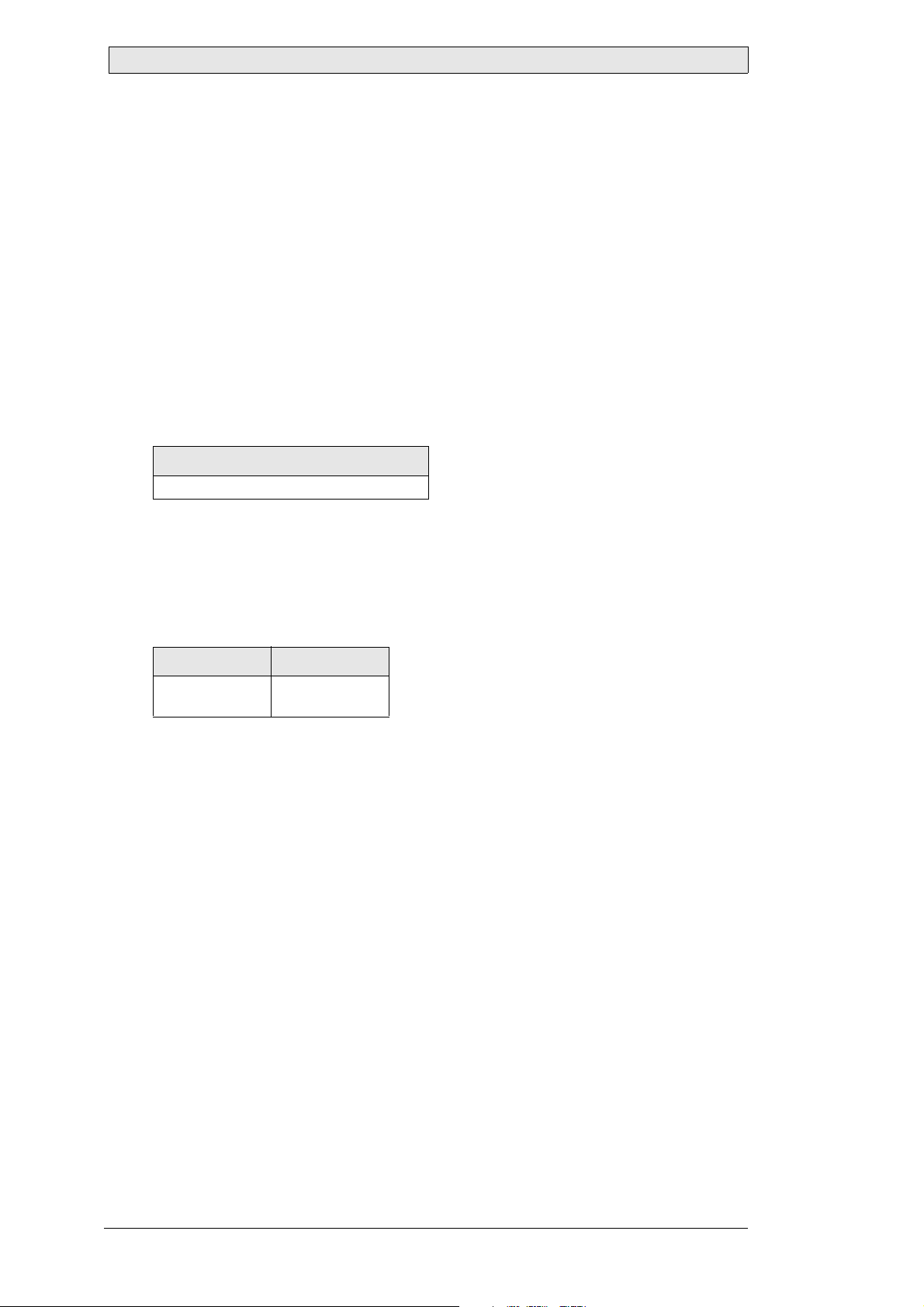
This is the default configuration for the two interfaces:
Interface type Default configuration
Serial (RS232 or RS485) 9600 bits/second, 8 data bits, 1 start bit, 1 stop bit, no parity
USB Full speed
Beijer Electronics, MAEN993 5
Page 6
Message Format and Description
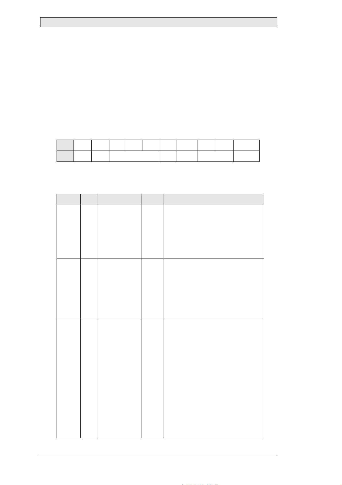
2 Message Format and Description
An SCOM message is a stream of bytes, containing the destination, type of message
and the corresponding data, if available. The complete stream is protected by two
checksums. Data transfer is initiated by sending a command message. Depending on
the command, a response message may be sent back. Some commands may contain
sub-commands and data, which are sent in the data field of the message.
SCOM Message Basic Format
Byte
Field
012345 6 7...7 + [LEN]
ATN ADR CMD LEN ICHKH DATA ICHKD
Each field of the message is described in the following table:
Byte Field Value Size Description
0ATN
1ADR
2
34CMD
0x07 (BELL):
Command
0x06 (ACK):
Acknowledge
0x15 (NAK):
Negative
Acknowledge
0x00 to 0xEF:
Device group/
address
0xFF:
Broadcast address
0xF0 to 0xFE:
Unused address
range
0x42 0x52 0x54:
“BRT”
0x4D 0x41 0x4E:
“MAN”
0x56 0x45 0x52:
“VER”
0x50 0x4F 0x54:
“POT”
0x4D 0x43 0x43:
“MCC”
0x54 0x59 0x50:
“TYP”
0x45 0x54 0x43:
“ETC”
0x4C 0x41 0x55:
“LAU”
1 byte
1 byte
3 bytes
Identifies the start of a new message. T he
type of message is given by its value. Data
transfer is always initiated by using the
Command message type. Depending on
the command, a response message of type
Acknowledge or Negative Acknowledge
may be sent back by the destination.
Defines the destination of a command
message or the source of the response
message. A unique device group/address
can be assigned to each device in a
network, and then individually address ed
using this field. By default, all devices
also support the Broadcast address and
can be controlled simultaneously. In this
case, no response messages are sent.
Contains the main command supported in
the current firmware version.
Please refer to section Command
Reference for a description of commands
and sub-commands.
6 Beijer El ectr onics, MAEN99 3
Page 7
Message Format and Description
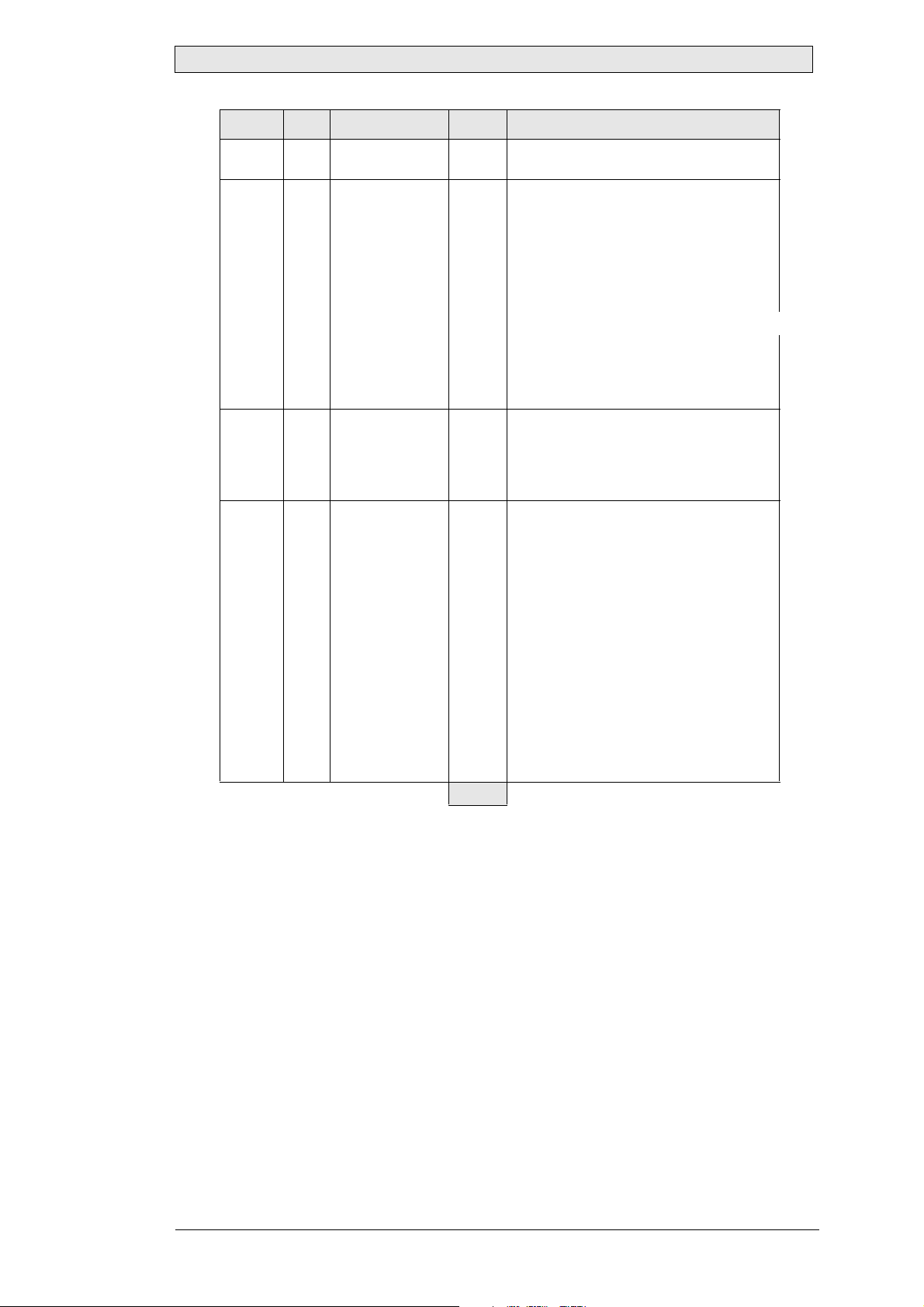
Byte Field Value Size Description
5LEN
6ICHKH... 1 byte
7
...
7 + [LEN] ICHKD ... 1 byte
0 to 74
(0x00 to 0x4A)
DATA ...
1 byte
0 to 74
bytes
82 bytes
The size of the DATA-field in bytes.
To protect the message header
(bytes 0 to 5), a simple 8-bit checksum is
calculated as follows:
Calculate the sum of bytes 0 to 5.
1.
Reduce the sum width to 8 bits
2.
(AND 0xFF).
3.
Invert all bits. The result is ICHKH.
The checksum is verified as follows:
Calculate the sum of bytes 0 to 6.
1.
Reduce the sum width to 8 bits (AND
2.
0xFF).
3.
The result should be 0xFF.
Optional field.
If the LEN-field is not 0, this field contains
sub-commands and/or data for the
specified command. If the LEN -f ie l d is 0,
no data is avail a bl e .
Optional field. Only sent if data is
available (LEN ≠ 0).
T o protect the data (bytes 7 to 7+(LEN-1)),
a simple 8-bit checksum is calculated as
follows:
1.
Calculate the sum of bytes 7 to
7+(LEN-1)
2.
Reduce the sum width to 8 bits (AND
0xFF)
3.
Invert all bits. The result is ICHKD.
The checksum is verified as follows:
1.
Calculate the sum of bytes 7 to 7+LEN
2.
Reduce the sum width to 8 bits (AND
0xFF)
3.
The result should be 0xFF
As shown in the table, the DATA field is optional. If the message does not require
any data, the value of LEN is 0 and the field ICHKD is not used and not sent. In
this case the message has the minimum SCOM size of 7 bytes (bytes 0 to 6).
If a command requires data to be sent, the maximum size of an SCOM message is 82
bytes. This means, that the last field ICHKD is located at the offset of the first data
byte plus the value of the LEN field.
The maximum value of the LEN field is 74, which is calculated as:
[LEN] = max. message size - (min. message size + ICHKD size)
or
82 - (7 + 1) = 74
Beijer Electronics, MAEN993 7
Page 8
Device Addressing
3 Device Addressing
By default, a Beijer Electronics RBC supports the standard SCOM addressing
scheme, which allows a total count of 16 devices within a network. The address of a
device is set with four DIP switches. If an SCOM command is sent to a device, the
ADR field must contain either the broadcast address 0xFF, or the address of the destination device set by the DIP switches. To eliminate this limit, a new addressing
scheme is supported by the Beijer Electronics RBC.
According to the previous chapter, the width of the ADR field is 1 byte (or 8 bits).
The standard SCOM addressing scheme uses only the lower 4 bits of this field (only
in case of the broadcast address, all bits are used), allowing a maximum of 16 addresses.
Related information
Message Format and Description
The new addressing scheme, implemented in Beijer Electronics RBC, uses also the 4
upper bits. To distinguish between the standard and new addressing scheme, these
bits are called “group bits” or simply “group”. Based on this definition, the following
table shows field ADR in more detail:
ADR bits 15...8 ADR bits 7...0
Group
(0 … 14)
Address
(0 … 15)
As shown in the table, a group between 0 and 14 can be specified. Group 15 is not
supported, to avoid address collision with the broadcast address. Thus, together with
the address field, a total count of 15 x 16 = 240 devices can be connected to one network.
Grouping of devices is activated only, if the devices are set up to use the software configured address, instead of the hardware address specified by the DIP switches. If the
device uses the hardware address, the group address is automatically set to 0, regardless of the group configuration.
Beijer Electronics RBC addresses are always given in a dotted notation as “group.address”. This means, if a device belongs to group 7 and its address is 3, the resulting
address will be 7.3, which is 115 (0x73). In the standard mode (i.e. DIP switch address is used), the device address will be 0.3 (or simply 3) for the given example, because the group bits are set to 0.
If a Beijer Electronics RBC is configured as remote controller (default), it addresses
all reachable devices by sending a broadcast command.
8 Beijer El ectr onics, MAEN99 3
Page 9

Protocol Description and Timings
4 Protocol Description and Timings
The protocol used for transferring SCOM messages and receiving response messages
is optimized for easy software implementation. Regardless of the type of interface, a
connected device is always passive and listening for a command to be received by any
available communication interface. A Beijer Electronics RBC never sends SCOM
messages by itself, unless it is configured as a remote controller.
If a device receives an SCOM message from any interface, it verifies the message and
checks the address field ADR. In case of an address match between the received address and the device address, the command is processed.
If the broadcast address 0xFF is received, a command is always processed by any device in the network. Depending on the received address and the type of the interface,
a response message (ACK or NAK) might be sent back to the interface, from which
the command was received.
If a device is individually addressed and a serial port (RS232 or RS485) is used, the
next command shall not be sent until a delay time called Inter-message gap. The
Inter-message gap depends on the baud rate and is calculated as shown below:
5 x 10
Ti =
b
Ti: Inter-message ga p [s]
b: Baud rate [bits/second]
Example
Inter-message gap at 9600 baud: Ti = 5 x 10 / 9600 ≈ 0.0052 s = 5.2 ms
Beijer Electronics, MAEN993 9
Page 10
Protocol Description and Timings
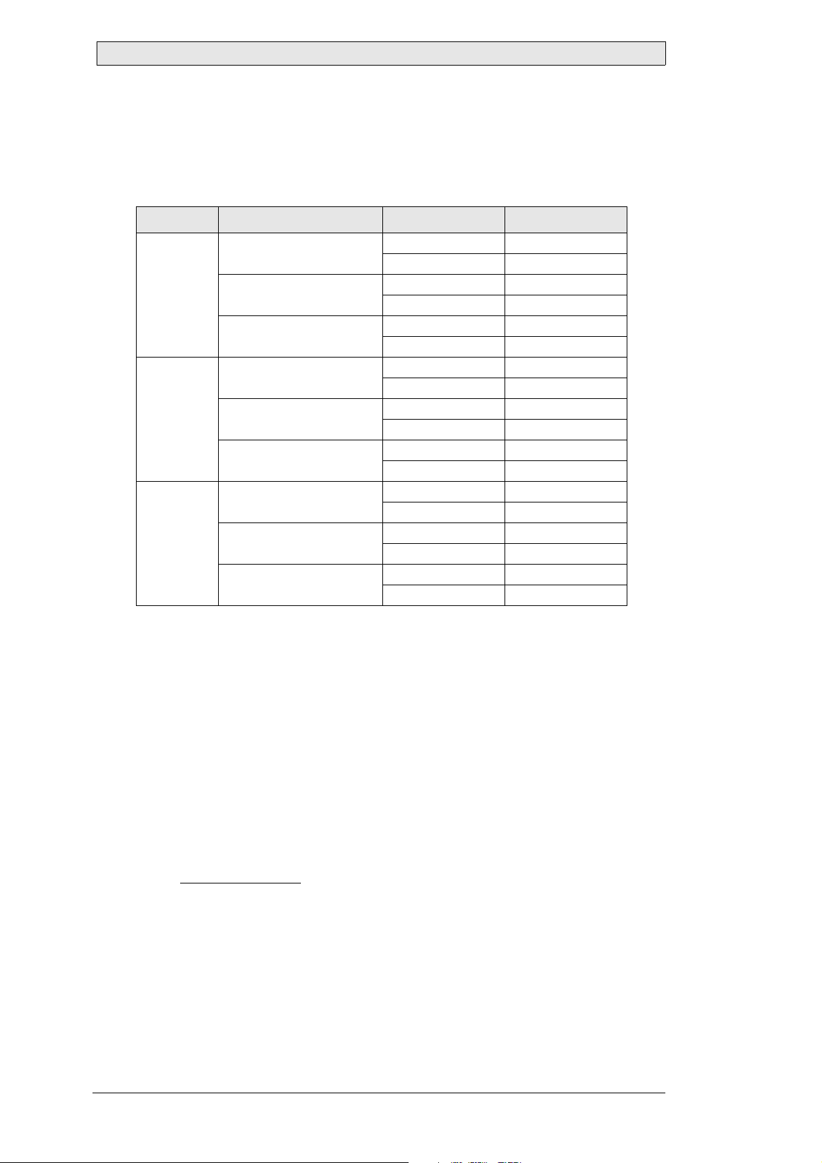
Conditions for Response Message
The conditions for a response message generated by the Beijer Electronics RBC are
described below:
Interface Addr ess condition Command status Response
RS232 Address does not match
device address
Address matches device
address
Address is Broadcast
address (0xFF )
RS485 Address does not match
device address
Address matches device
address
Address is Broadcast
address (0xFF )
USB Address does not match
device address
Address matches device
address
Address is Broadcast
address (0xFF )
Delayed Response
not EXECUTED No response
not EXECUTED No response
if COMPLETED ACK
if FAILED NAK
if COMPLETED ACK
if FAILED NAK
not EXECUTED No response
not EXECUTED No response
if COMPLETED ACK
if FAILED NAK
if COMPLETED Delayed ACK
if FAILED No response
not EXECUTED No response
not EXECUTED No response
if COMPLETED ACK
if FAILED NAK
if COMPLETED ACK
if FAILED NAK
If a Beijer Electronics RBC receives an SCOM message with a broadcast address from
the RS485 interface and the command is completed, the generated response message
is sent after a delay time. This is required, because many devices can be attached to
the RS485 bus, but only one device can claim the line for its communication. The
delay guarantees that each response message is sent one after one, even if all devices
have received the broadcast message and processed it at the same time, avoiding a collision on the RS485 bus.
The length of the delay time depends on the device address and maximum length of
a response message, and is calculated according to the following formula:
(2.5 + Lr) x 10 x N
Te =
b
Te: Bro ad cast command response [s]
Lr: Maximum length of response message
N: Device address + 1
b: Baud rate [bits/second]
10 Beijer Electronics, MAEN993
Page 11

Protocol Description and Timings
The Lr value depends on the command, for which the response message is generated.
Detailed information and the “Maximum Lr value” for each response message can be
found in Command Reference chapter.
Note:
The given “Maximum Lr value” is specified for a valid command. If an invalid command
with a data field exceeding the specifica tion is sent, the Lr value will grow accordingly.
Related information
Command Reference
Example
Broadcast command response for command BRT, sent by device with address 7 at
9600 baud: Te = (2.5 + 9) x 10 x 8 / 9600 ≈ 0.0958 s = 95.8 ms
The delay time Te is inserted by the device automatically, only if the RS485 interface
is selected for the communication. If the RS232 or USB interface is used, the response message is generated and sent as fast as possible.
The RS232 communication does not require a delay time due to the point-to-point
communication, where only two devices can be attached to the line (i.e. host and
Beijer Electronics RBC or Beijer Electronics RBC and Beijer Electronics RBC). USB
communication is similar to the RS485 communication, where many devices can be
attached to the same line. However, in contrast to the RS485 interface, a collision is
handled by the USB architecture and software, so there is no need for anti-collision
support within the device.
Beijer Electronics, MAEN993 11
Page 12

Protocol Description and Timings
12 Beijer Electronics, MAEN993
Page 13

Command Reference
5 Command Reference
The Lauer SCOM protocol exposes many commands for remote control of a Beijer
Electronics RBC by a dedicated software. It supports all standard SCOM commands,
as well as the new Lauer command set for special purpose functions.
This chapter describes each SCOM command and sub-commands for the currently
available device, Beijer Electronics RBC.
Although each Beijer Electronics RBC is based on the same base firmware and uses
the same communication, some commands/sub-commands are hardware dependant
and not supported for each device of the series, due to the differences within the device hardware. These differences and required firmware versions are indicated in detail for each command description.
Note:
Response messages may be generated and sent back, even if the commands/sub commands are not supported within a particular firmware version or if they are invalid.
Beijer Electronics, MAEN993 13
Page 14
Command Reference
5.1 BRT
Backlight Brightness
Sets the backlight level to the given value. This command affects only the brightness
of the backlight lamp or LED array, not the brightness value of the video controller.
Supported since Firmware Version
LAUER RBC: 0.0.0.1
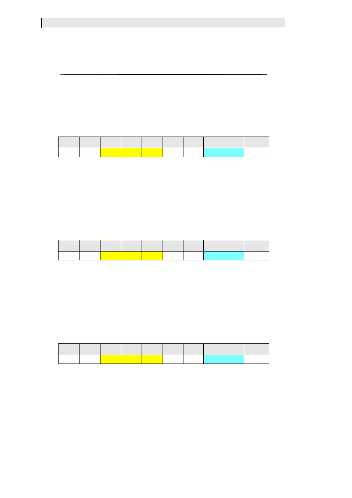
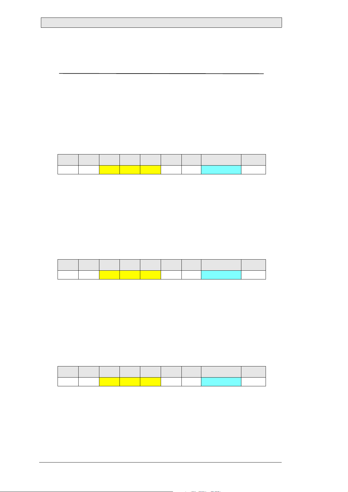
Command Stream
0 1 2 3 4 5 6 7 8
0x07 ADR 0x42 0x52 0x54 0x01 ICHKH Backlight level ICHKD
Backlight level
Value: 0: dark … 255: bright
Type: Byte
Length: 1
Descript i on: New backlight level
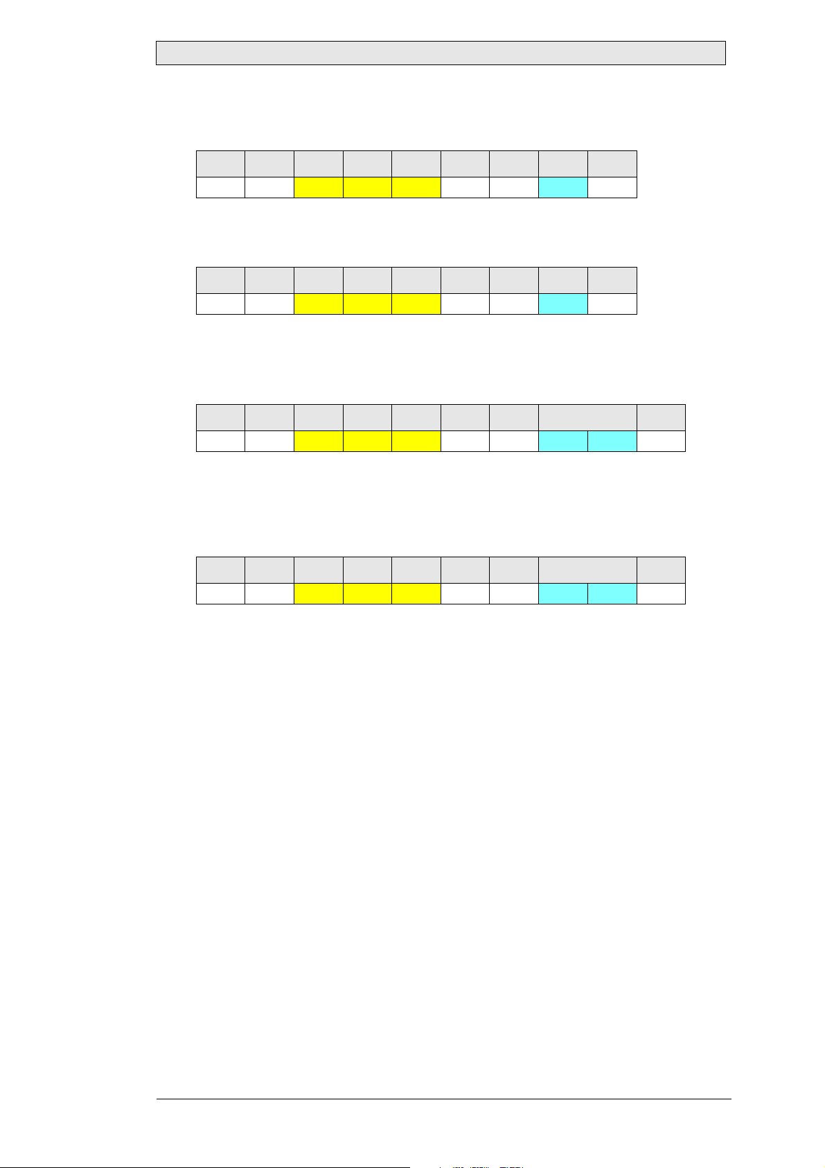
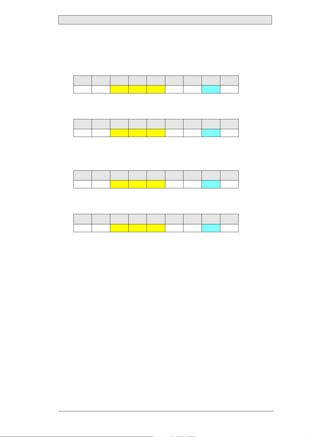
Response Message (Ack n o wledge)
0 1 2 3 4 5 6 7 8
0x06 ADR
Backlight level
0x42 0x52 0x54 0x01 ICHKH Backlight level ICHKD
Value: 0: dark … 255: bright
Type: Byte
Length: 1
Descript i on: Current backlight l evel
Response Message (Negati v e Ack n owl ed g e)
0 1 2 3 4 5 6 7 8
0x15 ADR
Backlight level
0x42 0x52 0x54 0x01 ICHKH Backlight level ICHKD
Value: 0: dark … 255: bright
Type: Byte
Length: 1
Description: Last backlight level
Maximum Lr for this Command
9
14 Beijer Electronics, MAEN993
Page 15
Command Reference
Example 1
Set the backlight level of device at address 0.7 (group 0, address 7) to 130 (0x82):
0 1 2 3 4 5 6 7 8
0x07 0x07 0x42 0x52 0x54 0x01 0x08 0x82 0x7D
Device at address 0.7 (group 0, address 7) has acknowledged the new backlight level
130 (0x82):
0 1 2 3 4 5 6 7 8
0x06 0x07 0x42 0x52 0x54 0x01 0x09 0x82 0x7D
Example 2
Send an invalid “BRT” command to the device at address 0.7 (group 0, address 7).
The command has two data bytes, but “BRT” accepts only one byte:
0 1 2 3 4 5 6 7...8 9
0x07 0x07 0x42 0x52 0x54 0x02 0x07 0xFF 0xFF 0x01
Device at address 0.7 (group 0, address 7) has not accepted the command. Instead,
it sent a negative acknowledge with the current backlight level 128 (0x80). The
length of the response message exceeds the specified value 9, because of the invalid
data field length:
0 1 2 3 4 5 6 7...8 9
0x15 0x07 0x42 0x52 0x54 0x02 0xF9 0x82 0xFF 0x80
Beijer Electronics, MAEN993 15
Page 16
Command Reference
5.2 MAN
Manufacturer ID
Requests the manufacturer ID from the device. The manufacturer ID is a short, max.
7 character ASCII-string containing the manufacturer specific code.
For devices manufactured by Beijer Electronics, the returned code is always “LAU”.
Supported since Firmware Version
LAUER RBC: 0.0.0.1
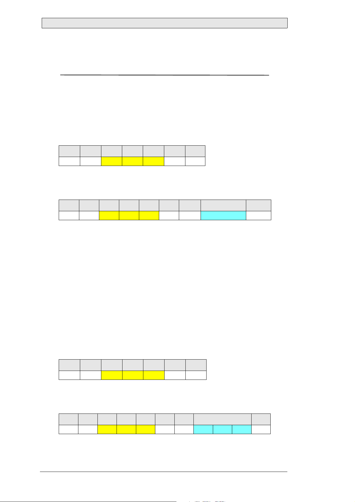
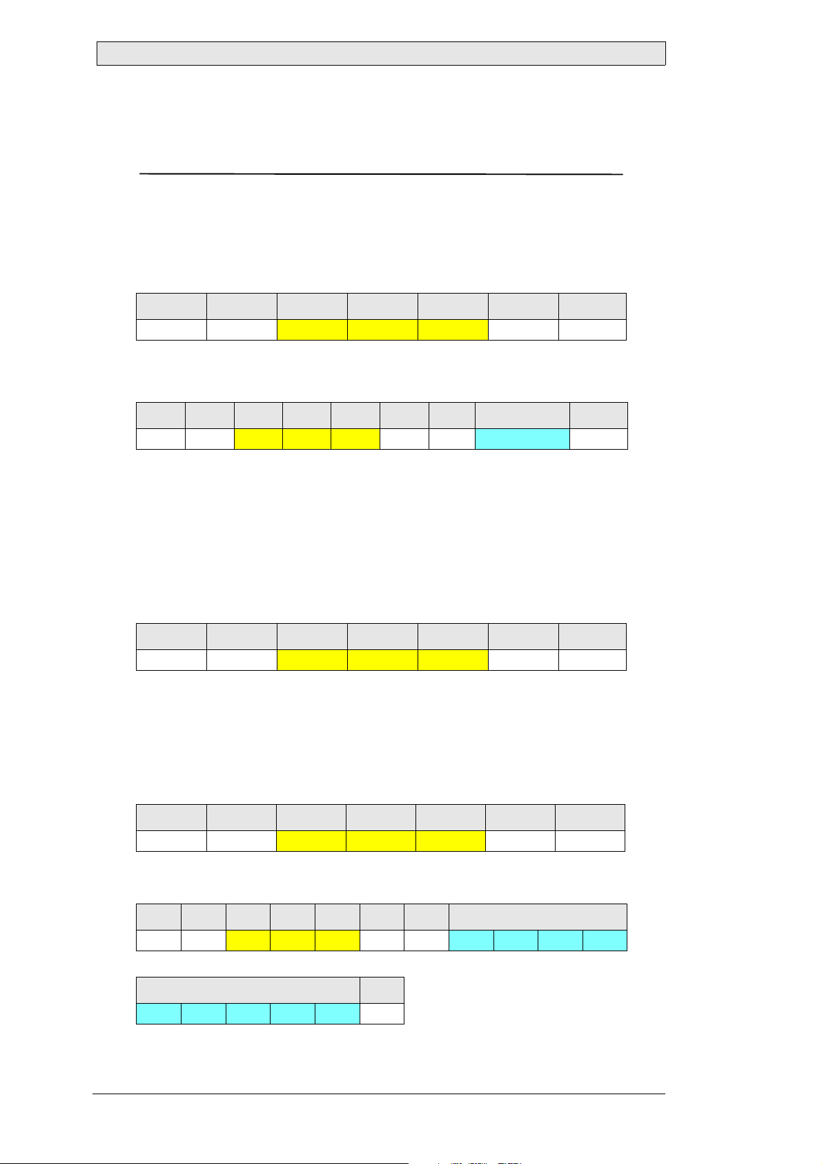
Command Stream
0 1 2 3 4 5 6
0x07 ADR
0x4D 0x41 0x4E 0x00 ICHKH
(This command has no data)
Response Message (Ack n o wledge)
0 1 2 3 4 5 6 7...7+[LEN]-1 7+[LEN]
0x06 ADR
Manufacturer ID
0x4D 0x41 0x4E LEN ICHKH Manufacturer ID ICHKD
Value: ASCII characters
Type: String
Length: 0...7
Description: ASCII-string containing the manufacturer ID
Response Message (Negati v e Ack n owl ed g e)
Under normal operation conditions, a device never sends a negative acknowledge in
response to this command.
Maximum Lr for this Command
15
Example
Query the manufacturer ID of the device at address 0.7 (group 0, address 7):
0 1 2 3 4 5 6
0x07 0x07 0x4D 0x41 0x4E 0x00 0x15
The device at address 0.7 (group 0, address 7) has returned “0x4C 0x41 0x55”, which
represents the ASCII-string “LAU”, indicating that the device is manufactured by
Beijer Electronics:
0 1 2 3 4 5 6 7...9 10
0x06 0x07
16 Beijer Electronics, MAEN993
0x4D 0x41 0x4E 0x03 0x13 0x4C 0x41 0x55 0x1D
Page 17
Command Reference
5.3 VER
Unit ID and Model / Version Number
Requests the preassigned unit ID and model code, and the version of the serial
communications interface software. For compatibility reasons, this code is always
static and does not return information specific to Beijer Electronics RBC. To get device informations specific to Beijer Electronics RBC, such as firmware version etc.,
use the Lauer Extension command “LAU”.
Supported since Firmware Version
LAUER RBC: 0.0.0.1
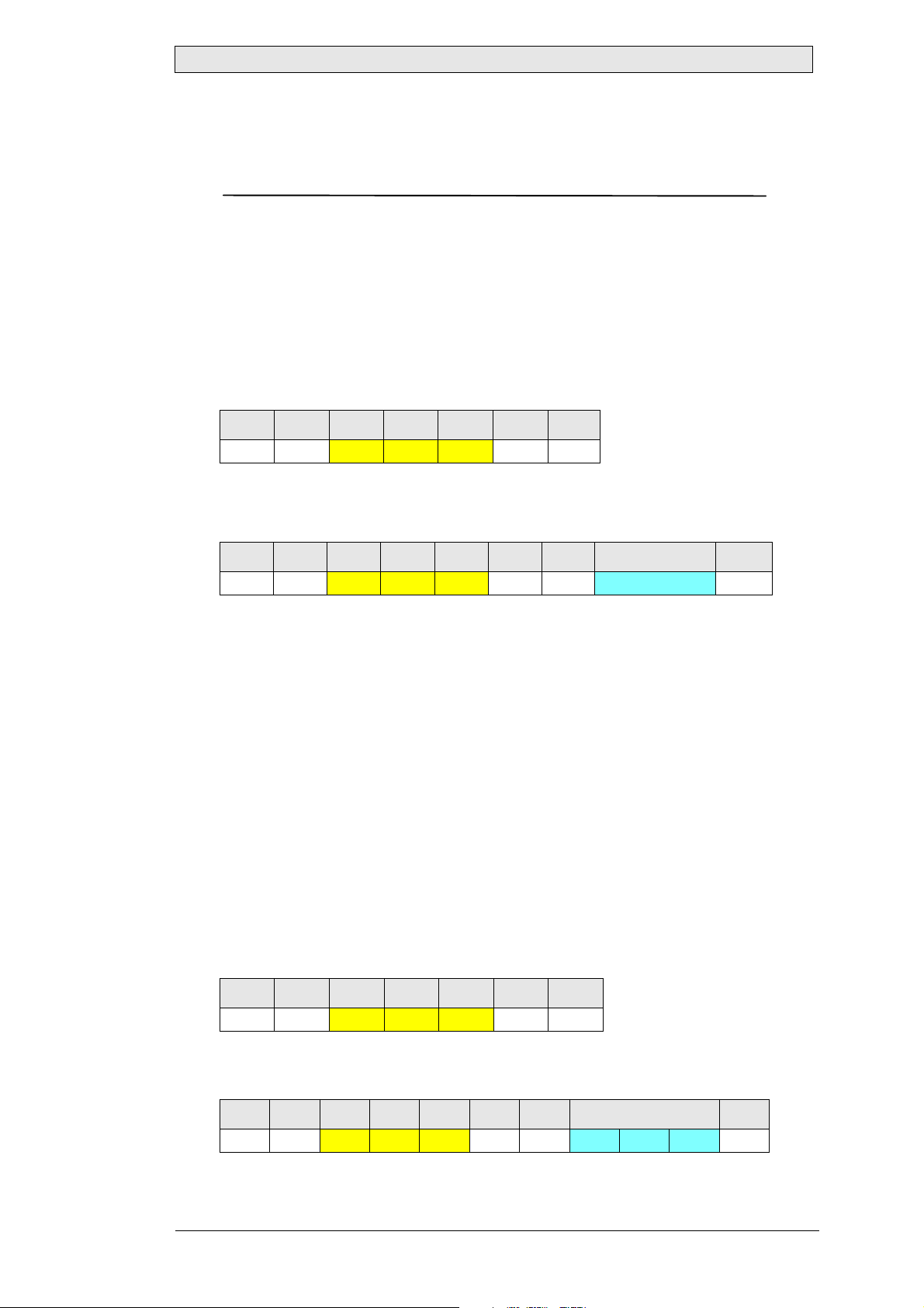
Command Stream
0 1 2 3 4 5 6
0x07 ADR 0x56 0x45 0x52 0x00 ICHKH
(This command has no data)
Response Message (Acknowledge)
0 1 2 3 4 5 6 7...9 10
0x06 ADR
Unit ID / Version
0x56 0x45 0x52 0x03 ICHKH Unit ID / Version ICHKD
Value: 0…255 each byte
Type: Byte array
Length: 3
Description: Static unit ID, model and version number
Response Message (Negative Acknowledge)
Under normal operation conditions, a device never sends a negative acknowledge in
response to this command.
Maximum Lr for this Command
11
Example
Query the unit ID, model and version number of the device at address 0.7 (group 0,
address 7):
0 1 2 3 4 5 6
0x07 0x07 0x56 0x45 0x52 0x00 0x04
The device at address 0.7 (group 0, address 7) has returned “0x01 0x01 0x00”, which
indicates model 1, version 1.0:
0 1 2 3 4 5 6 7...9 10
0x06 0x07 0x56 0x45 0x52 0x03 0x02 0x01 0x01 0x00 0xFD
Beijer Electronics, MAEN993 17
Page 18
Command Reference
5.4 POT
Local Control
Enables or disables the local backlight level control. If the local backlight control is
enabled, the backlight level can be changed using the front panel buttons and by remote control (RS232, RS485 or USB interface). If the local backlight control is disabled, the backlight level cannot be changed using the front panel buttons. It can still
be changed by any remote control message.
Supported since Firmware Version
LAUER RBC: 0.0.0.1
Command Stream
0 1 2 3 4 5 6 7 8
0x07 ADR 0x50 0x4F 0x54 0x01 ICHKH Local control ICHKD
Local control
Value: 0x00: Disable local backlight control
0xFF: Enable local backlight control
Type: Byte
Length: 1
Description: New local control configuration
Response Message (Ack n o wledge)
0 1 2 3 4 5 6 7 8
0x06 ADR 0x50 0x4F 0x54 0x01 ICHKH Local control ICHKD
Local control
Value: 0x00: Local backlight control disabled
0xFF: Local backlight control enabled
Type: Byte
Length: 1
Description: Current local control configuration
Response Message (Negati v e Ack n owl ed g e)
0 1 2 3 4 5 6 7 8
0x15 ADR 0x50 0x4F 0x54 0x01 ICHKH Local control ICHKD
Local control
Value: 0x00: Local backlight control disabled
0xFF: Local backlight control enabled
Type: Byte
Length: 1
Description: Last local backlight control configuration
18 Beijer Electronics, MAEN993
Page 19
Command Reference
Maximum Lr for this Command
9
Example 1
Disable the local control of device at address 0.7 (group 0, address 7):
0 1 2 3 4 5 6 7 8
0x07 0x07
0x50 0x4F 0x54 0x01 0xFD 0x00 0xFF
Device at address 0.7 (group 0, address 7) has acknowledged, that the local control
is disabled:
0 1 2 3 4 5 6 7 8
0x06 0x07
0x50 0x4F 0x54 0x01 0xFE 0x00 0xFF
Example 2
Send an invalid “POT” command to the device at address 0.7 (group 0, address 7).
The command uses an invalid value 0x90 for “Local control”:
0 1 2 3 4 5 6 7 8
0x07 0x07
0x50 0x4F 0x54 0x01 0xFD 0x90 0x6F
Device at address 0.7 (group 0, address 7) has not accepted the command. Instead,
it sent a negative acknowledge with the current local control mode 255 (0xFF):
0 1 2 3 4 5 6 7 8
0x15 0x07
0x50 0x4F 0x54 0x01 0xEF 0xFF 0x00
Beijer Electronics, MAEN993 19
Page 20
Command Reference
5.5 TYP
Unit Type and Model Number
Queries the device type and model.
Supported since Firmware Version
LAUER RBC: 0.0.0.1
Command Stream
0 1 2 3 4 5 6
0x07 ADR
0x54 0x59 0x50 0x01 ICHKH
(This command has no data)
Response Message (Ack n o wledge)
0 1 2 3 4 5 6 7...7+[LEN]-1 7+[LEN]
0x06 ADR 0x54 0x59 0x50 LEN ICHKH Type/Model ICHKD
Type/Model
Value: ASCII characters
Type: String
Length: 1...15
Descript i on: Devic e type and mode l
Response Message (Negati v e Ack n owl ed g e)
0 1 2 3 4 5 6
0x15 ADR
0x54 0x59 0x50 0x00 ICHKH
(No data is returned, in case of a negative acknowledge)
Maximum Lr for this Command
23
Example
Query the unit type and model of the device at address 0.7 (group 0, address 7):
0 1 2 3 4 5 6
0x07 0x07 0x54 0x59 0x50 0x00 0xF4
According to the data returned by the device (“Lauer RBC”) at address 0.7 (group 0,
address 7), this is a device of the Beijer Electronics RBC series:
0 1 2 3 4 5 6 7-15
0x06 0x07 0x54 0x59 0x50 0x09 0xEC 0x4C 0x61 0x75 0x65
7-15 16
0x72 0x20 0x52 0x42 0x43 0xB9
20 Beijer Electronics, MAEN993
Page 21

Command Reference
5.6 LAU
Lauer Extension
The Lauer Extension is a new SCOM command specially developed for Beijer Electronics RBC. It extends the standard SCOM command set with more powerful functions, which add special remote configuration, controlling and status capabilities to
each device.
The LAU command is a container for specific sub commands and their parameters.
They are encapsulated within the DATA field of the command stream. In contrast to
standard SCOM commands, a message returned in a response to Lauer Extension
command does not always contain the command itself. This means, a response message may contain the same data for different commands. Therefore, a response message should be processed immediately, after the command is sent.
The LAU command exposes the capabilities of a device model through SCOM.
While there is a base set of sub-commands, which are always supported on each device model, there are also sub-commands, which may expose the special capabilities
of a device, not available on other models.
The full LAU sub-command set is divided into three functional groups:
Group Purpose
CONFIGURATION Allows to query for or change the current device configuration.
CONTROL Intended to control a device or its hardware extensions, such as
buzzer, I/Os etc., during operation.
ST ATUS Used to query for the current device or hardware extension status,
such as IP address, buzzer stat e , analog/digital inputs etc.
For any LAU sub-command, the following command and response streams are generally common:
Command Stream
0 1 2 3 4 5 6 7...7+[LEN]-1 7+[LEN]
0x07 ADR
SCMD
FNC
Param
0x4C 0x41 0x55 LEN ICHKH SCMD FNC Param ICHKD
Sub-command (group)
Individual function in a group
Parameter for the function (optional)
Beijer Electronics, MAEN993 21
Page 22

Command Reference
Response Message (Ack n o wledge)
0 1 2 3 4 5 6 7...7+[LEN]-1 7+[LEN]
0x06 ADR 0x4C 0x41 0x55 LEN ICHKH Ret ICHKD
Ret
Data returned by the device, if available
The following sections describe all supported LAU sub-commands in each functional
group in the order CONFIGURATION, CONTROL and STATUS.
22 Beijer Electronics, MAEN993
Page 23

Command Reference
5.6.1 LAU_CONFIG_GETFWVERSION (0x0101) Firmware Version
Returns the current firmware name and version including build date.
Supported since Firmware Version
LAUER RBC: 0.0.0.1
Command Stream
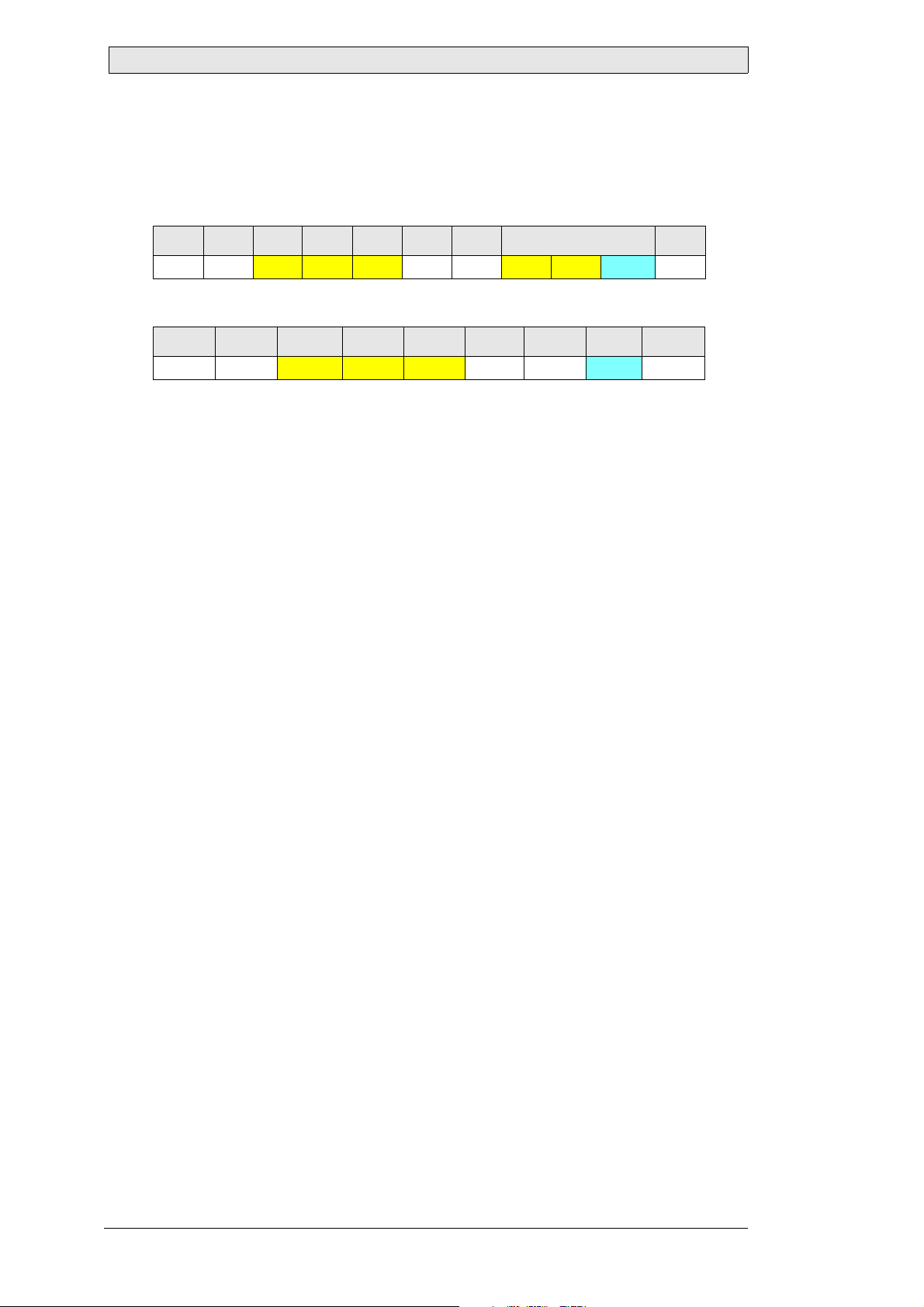
0 1 2 3 4 5 6 7...8 9
0x07 ADR
0x4C 0x41 0x55 0x02 ICHKH 0x01 0x01 ICHKD
Response Message (Acknowledge)
0 1 2 3 4 5 6 7...7+[LEN]-1 7+[LEN]
0x06 ADR
Ret
0x4C 0x41 0x55 LEN ICHKH Ret ICHKD
Value: ASCII characters
Type: String
Length: 0...74
Description: ASCII-string containing firmware version information
Response Message (Negative Acknowledge)
Under normal operation conditions, a device never sends a negative acknowledge in
response to this command.
Maximum Lr for this Command
82
Example
Read the firmware version from device at address 0.7 (group 0, address 7):
0 1 2 3 4 5 6 7...8 9
0x07 0x07
0x4C 0x41 0x55 0x02 0x0D 0x01 0x01 0xFD
According to the data returned by the device at address 0.7 (group 0, address 7), the
firmware version is “0001.02022009” which means version 0.0.0.1 from February 3,
2009:
0 1 2 3 4 5 6 7...19
0x06 0x07 0x4C 0x41 0x55 0x0D 0x03 0x30 0x30 0x30 0x31
7...19 20
0x2E 0x30 0x33 0x30 0x32 0x32 0x30 0x30 0x39 0x80
Beijer Electronics, MAEN993 23
Page 24

Command Reference
5.6.2 LAU_CONFIG_GETMANUFACTURER (0x010C)
Manufacturer
Requests the manufacturer ID from the device. The manufacturer ID is a short, max.
7 character ASCII-string containing the manufacturer specific code. For devices
manufactured by Beijer Electronics, the returned code is always “LAU”. Actually, this
command returns the same value as the standard SCOM command “MAN”.
Supported since Firmware Version
LAUER RBC: 0.0.0.1
Command Stream
0 1 2 3 4 5 6 7...8 9
0x07 ADR
0x4C 0x41 0x55 0x02 ICHKH 0x01 0x0C ICHKD
Response Message (Ack n o wledge)
0 1 2 3 4 5 6 7...7+[LEN]-1 7+[LEN]
0x06 ADR
Ret
0x4C 0x41 0x55 LEN ICHKH Ret ICHKD
Value: ASCII characters
Type: String
Length: 0...7
Description: ASCII-string containing the manufacturer ID
Response Message (Negati v e Ack n owl ed g e)
Under normal operation conditions, a device never sends a negative acknowledge in
response to this command.
Maximum Lr for this Command
15
Example
Query the manufacturer ID of the device at address 0.7 (group 0, address 7):
0 1 2 3 4 5 6 7...8 9
0x07 0x07 0x4C 0x41 0x55 0x02 0x0D 0x01 0x0C 0xF2
The device at address 0.7 (group 0, address 7) has returned “0x4C 0x41 0x55”, which
represents the ASCII-string “LAU”, indicating that the device is manufactured by
Beijer Electronics:
0 1 2 3 4 5 6 7...9 10
0x06 0x07
24 Beijer Electronics, MAEN993
0x4C 0x41 0x55 0x03 0x0D 0x4C 0x41 0x55 0x1D
Page 25

Command Reference
5.6.3 LAU_CONFIG_GETDEVICENAME (0x010D) Device Name
Returns the device type and model. Actually, this command returns the same value
as the standard SCOM command “TYP”.
Supported since Firmware Version
LAUER RBC: 0.0.0.1
Command Stream
0 1 2 3 4 5 6 7...8 9
0x07 ADR
0x4C 0x41 0x55 0x02 ICHKH 0x01 0x0D ICHKD
Response Message (Acknowledge)
0 1 2 3 4 5 6 7...7+[LEN]-1 7+[LEN]
0x06 ADR
Ret
0x4C 0x41 0x55 LEN ICHKH Ret ICHKD
Value: ASCII characters
Type: String
Length: 0...15
Description: Device type and model
Response Message (Negative Acknowledge)
Under normal operation conditions, a device never sends a negative acknowledge in
response to this command.
Maximum Lr for this Command
23
Example
Query the unit type and model of the device at address 0.7 (group 0, address 7):
0 1 2 3 4 5 6 7...8 9
0x07 0x07
0x4C 0x41 0x55 0x02 0x0D 0x01 0x0D 0xF1
According to the data returned by the device at address 0.7 (group 0, address 7), this
is a Beijer Electronics RBC:
0 1 2 3 4 5 6 7...15
0x06 0x07
0x72 0x20 0x52 0x42 0x43 0x0F
Beijer Electronics, MAEN993 25
0x4C 0x41 0x55 0x0E 0x02 0x4C 0x61 0x75 0x65
7...15 16
Page 26

Command Reference
5.6.4 LAU_CONFIG_GETDILMODE (0x010E) DIL Switch Mode
For a base configuration, Beijer Electronics RBCs are equipped with DIL (DIP)
switches, where the device address and the serial interface mode can be selected. Besides this configuration option, Beijer Electronics RBCs allow full software configuration, which is stored in an internal flash memory. The software configuration also
includes device address and serial interface mode setting. The value returned with
this command indicates whether the device uses hardware settings selected with the
DIL switches, or software settings stored in the internal memory.
Supported since Firmware Version
LAUER RBC: 0.0.0.1
Command Stream
0 1 2 3 4 5 6 7...8 9
0x07 ADR
0x4C 0x41 0x55 0x02 ICHKH 0x01 0x0E ICHKD
Response Message (Ack n o wledge)
0 1 2 3 4 5 6 7 8
0x06 ADR
Ret
Value: 0x00: Device is configured to use the DIL switch settings
Type: Byte
Length: 1
Description: Indicates whether the dev ice sh ould the DIL switch settings
0x4C 0x41 0x55 0x01 ICHKH Ret ICHKD
0x01: Device is configured to use the software settings
Response Message (Negati v e Ack n owl ed g e)
Under normal operation conditions, a device never sends a negative acknowledge in
response to this command.
Maximum Lr for this Command
9
Example
Check, whether the device at address 0.7 (group 0, address 7) overrides the DIL settings (i.e. device address and serial interface mode):
0 1 2 3 4 5 6 7...8 9
0x07 0x07
0x4C 0x41 0x55 0x02 0x0D 0x01 0x0E 0xF0
According to the data returned by the device at address 0.7 (group 0, address 7), the
device uses DIL settings:
0 1 2 3 4 5 6 7 8
0x06 0x07
26 Beijer Electronics, MAEN993
0x4C 0x41 0x55 0x01 0x0F 0x00 0xFF
Page 27

Command Reference
5.6.5 LAU_CONFIG_GETDISPLAYADR (0x010F) Device Address
Returns the software configured device address. This address is used, if the device is
configured to override the DIL (DIP) switch settings. The returned address does not
contain group information.
Supported since Firmware Version
LAUER RBC: 0.0.0.1
Command Stream
0 1 2 3 4 5 6 7...8 9
0x07 ADR 0x4C 0x41 0x55 0x02 IC HKH 0x01 0x0F ICHKD
Response Message (Acknowledge)
0 1 2 3 4 5 6 7 8
0x06 ADR 0x4C 0x41 0x55 0x01 ICHKH Ret ICHKD
Ret
Value: 0...15 (0x00...0x0F)
Type: Byte
Length: 1
Description: Software configured device address
Response Message (Negative Acknowledge)
Under normal operation conditions, a device never sends a negative acknowledge in
response to this command.
Maximum Lr for this Command
9
Example
Read the software configured device address (excluding group) from the device at address 14.7 (group 14, address 7):
0 1 2 3 4 5 6 7...8 9
0x07 0xE7
0x4C 0x41 0x55 0x02 0x2D 0x01 0x0F 0xEF
According to the data returned by the device at address 14.7 (group 14, address 7),
the devices software configured address without group is 0x07:
0 1 2 3 4 5 6 7 8
0x06 0xE7
Beijer Electronics, MAEN993 27
0x4C 0x41 0x55 0x01 0x2F 0x07 0xF8
Page 28

Command Reference
5.6.6 LAU_CONFIG_GETCOMSERMODE (0x0110)
SCOM Serial Interface Mode
The serial interface mode indicates the physical type of the serial interface used for
the SCOM communication. Available modes are RS232 and RS485. RS232 allows
a point-to-point communication, i.e. computer and Beijer Electronics RBC or Beijer
Electronics RBC and Beijer Electronics RBC. With RS485, many devices can be attached to the same physical line and can be controlled by one or more computers,
allowing a kind of networking.
Limitation is given only by the physical characteristics of the RS485 bus.
This command returns the software configured serial interface mode. It is used if the
device is configured to override the DIL switch settings. This mode may differ from
the current mode in use.
Supported since Firmware Version
LAUER RBC: 0.0.0.1
Command Stream
0 1 2 3 4 5 6 7...8 9
0x07 ADR
0x4C 0x41 0x55 0x02 ICHKH 0x01 0x10 ICHKD
Response Message (Ack n o wledge)
0 1 2 3 4 5 6 7 8
0x06 ADR
Ret
Value: 0x00: The serial inter face is configured as R S 232
Type: Byte
Length: 1
Description: Software configured serial interface mode used for SCOM
0x4C 0x41 0x55 0x01 ICHKH Ret ICHKD
0x01: The serial interface is c o n figured as RS485
communication
Response Message (Negati v e Ack n owl ed g e)
Under normal operation conditions, a device never sends a negative acknowledge in
response to this command.
Maximum Lr for this Command
9
Example
Get the serial interface configuration of the device at address 0.7 (group 0, address 7):
0 1 2 3 4 5 6 7...8 9
0x07 0x07
0x4C 0x41 0x55 0x02 0x0D 0x01 0x10 0xEE
According to the data returned by the device at address 10.7 (group 0, address 7), the
serial interface is configured as RS232:
0 1 2 3 4 5 6 7 8
0x06 0x07
28 Beijer Electronics, MAEN993
0x4C 0x41 0x55 0x01 0x0F 0x00 0xFF
Page 29

Command Reference
5.6.7 LAU_CONFIG_GETPOTMODE (0x0113) POT Mode
Returns the local backlight level control configuration. If the local backlight control
is enabled, the backlight level can be changed using the front panel buttons and by
remote control (via RS232, RS485 or USB interface). If the local backlight control
is disabled, the backlight level cannot be changed using the front panel buttons. It
can be still changed by any remote control option. The configured backlight level
control can be temporarily overridden by the SCOM command “POT”.
Supported since Firmware Version
LAUER RBC: 0.0.0.1
Command Stream
0 1 2 3 4 5 6 7...8 9
0x07 ADR 0x4C 0x41 0x55 0x02 IC HKH 0x01 0x13 ICHKD
Response Message (Acknowledge)
0 1 2 3 4 5 6 7 8
0x06 ADR 0x4C 0x41 0x55 0x01 ICHKH Ret ICHKD
Ret
Value: 0x00: Local backlight level control enabled
0x01: Local backlight level control disabled
Type: Byte
Length: 1
Description: Local backlight level control mode
Response Message (Negative Acknowledge)
Under normal operation conditions, a device never sends a negative acknowledge in
response to this command.
Maximum Lr for this Command
9
Example
Get the local backlight level control configuration of the device at address 0.7 (group
0, address 7):
0 1 2 3 4 5 6 7...8 9
0x07 0x07
0x4C 0x41 0x55 0x02 0x0D 0x01 0x13 0xEB
According to the data returned by the device at address 0.7 (group 0, address 7), the
local backlight level control is enabled:
0 1 2 3 4 5 6 7 8
0x06 0x07
Beijer Electronics, MAEN993 29
0x4C 0x41 0x55 0x01 0x0F 0x00 0xFF
Page 30

Command Reference
5.6.8 LAU_CONFIG_GETREMOTECONTROL (0x011C)
Remote Control Configuration
This command returns the configuration value that indicates whether the device is
configured to act as a remote controller. Beijer Electronics RBCs can be used as passive devices, but can also be set up as remote controller devices to alter the backlight
level of any other device within the network every time the backlight is changed by
the buttons at the front of the device.
Supported since Firmware Version
LAUER RBC: 0.0.0.1
Command Stream
0 1 2 3 4 5 6 7...8 9
0x07 ADR 0x4C 0x41 0x55 0x02 ICHKH 0x01 0x1C ICHKD
Response Message (Ack n o wledge)
0 1 2 3 4 5 6 7 8
0x06 ADR 0x4C 0x41 0x55 0x01 ICHKH Ret ICHKD
Ret
Value: 0x00: Remote control capability is disabled
0x01: Remote control capability is enabled
Type: Byte
Length: 1
Descript i on: Indicates whethe r the device is used also as remote contro ller
Response Message (Negati v e Ack n owl ed g e)
Under normal operation conditions, a device never sends a negative acknowledge in
response to this command.
Maximum Lr for this Command
9
Example
Check if the device at address 0.7 (group 0, address 7) is configured to control other
devices remotely within a network:
0 1 2 3 4 5 6 7...8 9
0x07 0x07
0x4C 0x41 0x55 0x02 0x0D 0x01 0x1C 0xE2
According to the data returned by the device at address 0.7 (group 0, address 7), the
device is capable to control other devices remotely within a network:
0 1 2 3 4 5 6 7 8
0x06 0x07
30 Beijer Electronics, MAEN993
0x4C 0x41 0x55 0x01 0x0F 0x01 0xFE
Page 31

Command Reference
5.6.9 LAU_CONFIG_GETSTARTUPBRIGHTNESSMODE (0x0124)
Startup Brightness Mode
The Beijer Electronics RBCs can be configured to start with different levels of brightness. There are four modes for the backlight at startup:
• Backlight is off
• Backlight has the same level as before it was turned off
• Backlight starts with the default brightness, which can be configured as well
• Backlight is on with maximum brightness
Supported since Firmware Version
LAUER RBC: 0.0.0.1
Command Stream
0 1 2 3 4 5 6 7...8 9
0x07 ADR
0x4C 0x41 0x55 0x02 ICHKH 0x01 0x24 ICHKD
Response Message (Acknowledge)
0 1 2 3 4 5 6 7 8
0x06 ADR
Ret
Value: 0x00: Device starts with minimum brightness (normally
Type: Byte
Length: 1
Description: Indicates at which level the backlight is set at startup
0x4C 0x41 0x55 0x01 ICHKH Ret ICHKD
backlight off)
0x01: Device starts with the same brightness as before it was
turned off
0x02: Device starts with defa ult br ightness
0x03: Device starts with maximum brightness
Response Message (Negative Acknowledge)
Under normal operation conditions, a device never sends a negative acknowledge in
response to this command.
Maximum Lr for this Command
9
Beijer Electronics, MAEN993 31
Page 32

Command Reference
Example
Check which mode the backlight of the device at address 0.7 (group 0, address 7) has
at startup:
0 1 2 3 4 5 6 7...8 9
0x07 0x07
0x4C 0x41 0x55 0x02 0x0D 0x01 0x24 0xDA
According to the data returned by the device at address 0.7 (group 0, address 7), it
does not use the broadcast address 0xFF, if remote controlling is enabled. Instead, it
uses configured device addresses:
0 1 2 3 4 5 6 7 8
0x06 0x07
0x4C 0x41 0x55 0x01 0x0F 0x02 0xFD
32 Beijer Electronics, MAEN993
Page 33

Command Reference
5.6.10LAU_CONFIG_GETSERIALNUMBER (0x0125)
Serial Number
Returns the serial number of the device.
Supported since Firmware Version
LAUER RBC: 0.0.0.1
Command Stream
0 1 2 3 4 5 6 7...8 9
0x07 ADR
0x4C 0x41 0x55 0x02 ICHKH 0x01 0x25 ICHKD
Response Message (Acknowledge)
0 1 2 3 4 5 6 7...8 9
0x06 ADR
Ret
Value: 0...65535
Type: Unsigned short
Length: 2
Description: The unique serial number
0x4C 0x41 0x55 0x02 ICHKH Ret ICHKD
Response Message (Negative Acknowledge)
Under normal operation conditions, a device never sends a negative acknowledge in
response to this command.
Maximum Lr for this Command
10
Example
Read the serial number of the device at address 0.7 (group 0, address 7):
0 1 2 3 4 5 6 7...8 9
0x07 0x07 0x4C 0x41 0x55 0x02 0x0D 0x01 0x25 0xD9
According to the data returned by the device at address 0.7 (group 0, address 7), its
serial number is 1 (0x0001):
0 1 2 3 4 5 6 7...8 9
0x06 0x07 0x4C 0x41 0x55 0x02 0x0E 0x01 0x00 0xFE
Beijer Electronics, MAEN993 33
Page 34

Command Reference
5.6.11LAU_CONFIG_GETDEFAULTBRIGHTNESS (0x0126)
Startup Brightness Mode
For the Beijer Electronics RBCs a default brightness can be stored. This brightness is
used in two cases:
1. To set the display to this brightness when both buttons (brighter and darker) on
the front unit are pressed for about 1 second.
2. When the device is turned on and the startup brightness mode is set to default
brightness.
Supported since Firmware Version
LAUER RBC: 0.0.0.1
Command Stream
0 1 2 3 4 5 6 7...8 9
0x07 ADR
0x4C 0x41 0x55 0x02 ICHKH 0x01 0x26 ICHKD
Response Message (Ack n o wledge)
0 1 2 3 4 5 6 7 8
0x06 ADR
Ret
Value: 0...255
Type: Byte
Length: 1
Description: Returns the default brightness
0x4C 0x41 0x55 0x01 ICHKH Ret ICHKD
Response Message (Negati v e Ack n owl ed g e)
Under normal operation conditions, a device never sends a negative acknowledge in
response to this command.
Maximum Lr for this Command
9
Example
Get the default brightness of the device at address 0.7 (group 0, address 7):
0 1 2 3 4 5 6 7...8 9
0x07 0x07
0x4C 0x41 0x55 0x02 0x0D 0x01 0x26 0xD8
The default brightness of the device at address 0.7 (group 0, address 7) is returned:
0 1 2 3 4 5 6 7 8
0x06 0x07
34 Beijer Electronics, MAEN993
0x4C 0x41 0x55 0x01 0x0F 0x22 0xDD
Page 35

Command Reference
5.6.12LAU_CONFIG_GETDISPLAYGROUP (0x0127)
Device Group
Besides the standard addressing scheme, where the lowest four address bits in field
ADR are used to address a total count of 16 devices in a network, the Beijer Electronics RBCs use also the upper four bits, that indicate a group of devices in a network
(max. 15 groups). This function returns the configured group the device belongs to.
It is only used, if the device is configured to override the DIL switch settings.
This group may differ from the current display group. The group does not contain
address information.
Supported since Firmware Version
LAUER RBC: 0.0.0.1
Command Stream
0 1 2 3 4 5 6 7...8 9
0x07 ADR
0x4C 0x41 0x55 0x02 ICHKH 0x01 0x27 ICHKD
Response Message (Acknowledge)
0 1 2 3 4 5 6 7 8
0x06 ADR
Ret
Value: 0...14
Type: Byte
Length: 1
Description: Configured display group
0x4C 0x41 0x55 0x01 ICHKH Ret ICHKD
Response Message (Negative Acknowledge)
Under normal operation conditions, a device never sends a negative acknowledge in
response to this command.
Maximum Lr for this Command
9
Example
Read the software configured display group from the device at address 14.7 (group
14, address 7), which is effective, if the DIL switch settings are ignored:
0 1 2 3 4 5 6 7...8 9
0x07 0xE7
0x4C 0x41 0x55 0x02 0x2D 0x01 0x27 0xD7
According to the data returned by the device at address 14.7 (group 14, address 7),
the device belongs to display group 14 (0x0E), if the DIL switch settings are ignored:
0 1 2 3 4 5 6 7 8
0x06 0xE7
Beijer Electronics, MAEN993 35
0x4C 0x41 0x55 0x01 0x2F 0x0E 0xF1
Page 36

Command Reference
5.6.13LAU_CONFIG_GETKEYPRESSMODE (0x012A)
Keypress Mode
The brightness of the Beijer Electronics RBCs can be configured adopt a determined
value if both dimmer keys are pressed for longer than one second. There are five keypress modes:
• Backlight turns to darkest possible value (off )
• Backlight turns to the level of the last received SCOM BRT command
• Backlight turns to the default brightness, which can be configured as well
• Backlight turns to brightest possible value
• Backlight does not change
Supported since Firmware Version
LAUER RBC: 0.0.0.2
Command Stream
0 1 2 3 4 5 6 7...8 9
0x07 ADR
0x4C 0x41 0x55 0x02 ICHKH 0x01 0x2A ICHKD
Response Message (Ack n o wledge)
0 1 2 3 4 5 6 7 8
0x06 ADR
Ret
Value: 0x00: Brightness is set to darkest possible value (off)
Type: Byte
Length: 1
Description: Indicates current keypress mode
0x4C 0x41 0x55 0x01 ICHKH Ret ICHKD
0x01: Brightness is set to the value o f the las t receiv ed SCOM
BRT command
0x02: Brightness is set to defaul t br i ghtness value
0x03: Brightness is set to brightest possible value
0x04: Brightness does not change
Response Message (Negati v e Ack n owl ed g e)
Under normal operation conditions, a device never sends a negative acknowledge in
response to this command.
Maximum Lr for this Command
9
36 Beijer Electronics, MAEN993
Page 37

Command Reference
Example
Check the keypress mode of the device at address 0.3 (group 0, address 3):
0 1 2 3 4 5 6 7...8 9
0x07 0x03 0x4C 0x41 0x55 0x02 0x11 0x01 0x2A 0xD4
According to the data returned by the device at address 0.3 (group 0, address 3), the
keypress mode is set to the default brightness value:
0 1 2 3 4 5 6 7 8
0x06 0x03 0x4C 0x41 0x55 0x01 0x13 0x02 0xFD
Beijer Electronics, MAEN993 37
Page 38

Command Reference
5.6.14LAU_CONFIG_SETDILMODE (0x018E)
DIL Switch Mode
For a base configuration, Beijer Electronics RBCs are equipped with DIL (DIP)
switches, where the device address and the serial interface mode can be selected. Besides this configuration option, Beijer Electronics RBCs allow full software configuration, which is stored in an internal Flash memory. The software configuration also
includes device address and serial interface mode setting. The value set by this command decides if the device uses hardware settings selected with the DIL switches, or
if it uses software settings stored in internal memory.
Note:
The changes made by this command will become active only after a restart of the device. This avoids loosing the connection to the device during configuration.
Supported since Firmware Version
LAUER RBC: 0.0.0.1
Command Stream
0 1 2 3 4 5 6 7...9 10
0x07 ADR 0x4C 0x41 0x55 0x03 ICHKH 0x01 0x8E Param ICHKD
Param
Value: 0x00: Configure the device to use the DIL switch settings
0x01: Configure the device to use the software settings
Type: Byte
Length: 1
Description: Use the D IL sw itch settings or the software settings
Response Message (Ack n o wledge)
0 1 2 3 4 5 6 7 8
0x06 ADR
Ret
Value: 0x00: Configure the device to use the DIL switch settings
Type: Byte
Length: 1
Description: Indicates whether the device uses the DIL switch settings or
0x4C 0x41 0x55 0x01 ICHKH Ret ICHKD
0x01: Configure the device to use the software settings
the software settings
Response Message (Negati v e Ack n owl ed g e)
Under normal operation conditions, a device never sends a negative acknowledge in
response to this command.
Maximum Lr for this Command
9
38 Beijer Electronics, MAEN993
Page 39

Command Reference
Example
Set the device at address 0.7 (group 0, address 7) in the mode to override the DIL
settings (i.e. device address and serial interface mode) with software settings:
0 1 2 3 4 5 6 7...9 10
0x07 0x07
0x4C 0x41 0x55 0x03 0x0C 0x01 0x8E 0x01 0x6F
According to the data returned by the device at address 0.7 (group 0, address 7), the
device uses software settings:
0 1 2 3 4 5 6 7 8
0x06 0x07
0x4C 0x41 0x55 0x01 0x0F 0x01 0xFE
Beijer Electronics, MAEN993 39
Page 40

Command Reference
5.6.15LAU_CONFIG_SETDISPLAYADR (0x018F)
Device Address
Stores a software address of a device in the internal memory. This address is used, if
the device is configured to override the DIL switch settings. Only the address is
changed; not the group.
Note:
The changes made by this command will become active only after a restart of the device. This avoids loosing the connection to the device during configuration.
Supported since Firmware Version
LAUER RBC: 0.0.0.1
Command Stream
0 1 2 3 4 5 6 7...9 10
0x07 ADR
Param
0x4C 0x41 0x55 0x03 ICHKH 0x01 0x27 Param ICHKD
Value: 0 ...15 (0x00 … 0x0F)
Type: Byte
Length: 1
Description: Software device address
Response Message (Ack n o wledge)
0 1 2 3 4 5 6 7 8
0x06 ADR 0x4C 0x41 0x55 0x01 ICHKH Ret ICHKD
Ret
Value: 0 ...15 (0x00 … 0x0F)
Type: Byte
Length: 1
Description: Software configured device address
Response Message (Negati v e Ack n owl ed g e)
Under normal operation conditions, a device never sends a negative acknowledge in
response to this command.
Maximum Lr for this Command
9
40 Beijer Electronics, MAEN993
Page 41

Command Reference
Example
Set the software configured device address (excluding group) from the device at address 14.7 (group 14, address 7) to 8:
0 1 2 3 4 5 6 7...9 10
0x07 0xE7
0x4C 0x41 0x55 0x03 0x2C 0x01 0x8F 0x08 0x67
According to the data returned by the device at address 14.7 (group 14, address 7),
the devices software configured address without group is 0x08:
0 1 2 3 4 5 6 7 8
0x06 0xE7
0x4C 0x41 0x55 0x01 0x2F 0x08 0xF7
Beijer Electronics, MAEN993 41
Page 42

Command Reference
5.6.16LAU_CONFIG_SETCOMSERMODE (0x0110)
SCOM Serial Interface Mode
The serial interface mode indicates the physical type of the serial interface used for
the SCOM communication. Available modes are RS232 and RS485. RS232 allows
a point-to-point communication, i.e. computer and Beijer Electronics RBC or Beijer
Electronics RBC and Beijer Electronics RBC. With RS485, many devices can be attached to the same physical line and can be controlled by one or more computers,
allowing a kind of networking. Limitation is given only by the physical characteristics
of the RS485 bus.
This command sets the software configured serial interface mode. It is used, if the
device is configured to override the DIL switch settings.
Note:
The changes made by this command will become active only after a restart of the device. This avoids loosing the connection to the device during configuration.
Supported since Firmware Version
LAUER RBC: 0.0.0.1
Command Stream
0 1 2 3 4 5 6 7...9 10
0x07 ADR 0x4C 0x41 0x55 0x03 ICHKH 0x01 0x10 Param ICHKD
Param
Value: 0x00: The serial interface will be configured as RS232
0x01: The serial interface will be configured as RS485
Type: Byte
Length: 1
Description: Software configured serial interface mode used for SCOM
communication
Response Message (Ack n o wledge)
0 1 2 3 4 5 6 7 8
0x06 ADR
0x4C 0x41 0x55 0x01 ICHKH Ret ICHKD
Ret
Value: 0x00: The serial interface is configured as RS232
0x01: The serial interface is configured as RS485
Type: Byte
Length: 1
Description: Indicates which interface is used if the software settings are
used
42 Beijer Electronics, MAEN993
Page 43

Command Reference
Response Message (Negative Acknowledge)
Under normal operation conditions, a device never sends a negative acknowledge in
response to this command.
Maximum Lr for this Command
9
Example
Get the serial interface configuration of the device at address 0.7 (group 0, address 7):
0 1 2 3 4 5 6 7...9 10
0x07 0x07 0x4C 0x41 0x55 0x03 0x2C 0x01 0x10 0x00 0xEE
According to the data returned by the device at address 0.7 (group 0, address 7), the
serial interface is configured as RS232:
0 1 2 3 4 5 6 7 8
0x06 0x07 0x4C 0x41 0x55 0x01 0x0F 0x00 0xFF
Beijer Electronics, MAEN993 43
Page 44

Command Reference
5.6.17LAU_CONFIG_SETREMOTECONTROL (0x019C)
Remote Control Configuration
This command returns a configuration value that indicates whether the device is configured to act as a remote controller. Beijer Electronics RBCs can be used as passive
devices, but can be additionally set up as remote controller devices to alter the backlight level of any other device within the network every time the backlight is changed
by the buttons on the front of the device.
Note:
The changes made by this command will become active only after a restart of the device.
Supported since Firmware Version
LAUER RBC: 0.0.0.1
Command Stream
0 1 2 3 4 5 6 7...9 10
0x07 ADR
Param
0x4C 0x41 0x55 0x03 ICHKH 0x01 0x9C Param ICHKD
Value: 0x00: Disable remote controlling capability
0x01: Enable remote controlling capability
Type: Byte
Length: 1
Description: Decides if the device is used also as remote controller
Response Message (Ack n o wledge)
0 1 2 3 4 5 6 7 8
0x06 ADR
Ret
Value: 0x00: Remote controlling capability i s disabled
Type: Byte
Length: 1
Description: Indicates whether the device is used als o as remote controller
0x4C 0x41 0x55 0x01 ICHKH Ret ICHKD
0x01: Remote controlling capability is enabled
Response Message (Negati v e Ack n owl ed g e)
Under normal operation conditions, a device never sends a negative acknowledge in
response to this command.
Maximum Lr for this Command
9
44 Beijer Electronics, MAEN993
Page 45

Command Reference
Example
Check if the device at address 0.7 (group 0, address 7) is configured to remote control
other devices within a network:
0 1 2 3 4 5 6 7...9 10
0x07 0x07
0x4C 0x41 0x55 0x03 0x0C 0x01 0x9C 0x01 0x61
According to the data returned by the device at address 0.7 (group 0, address 7), the
device is capable to remote control other devices within a network:
0 1 2 3 4 5 6 7 8
0x06 0x07
0x4C 0x41 0x55 0x01 0x0F 0x01 0xFE
Beijer Electronics, MAEN993 45
Page 46

Command Reference
5.6.18LAU_CONFIG_SETSTARTUPBRIGHTNESS MODE (0x01A4)
Startup Brightness Mode
The Beijer Electronics RBCs can be configured to start with different levels of brightness. There are four modes for the backlight at startup:
• Backlight is off
• Backlight has the same level as before it was turned off
• Backlight starts with the default brightness, which can be configured as well
• Backlight is on with maximum brightness
Note:
The changes made by this command will become active only after a restart of the device.
Supported since Firmware Version
LAUER RBC: 0.0.0.1
Command Stream
0 1 2 3 4 5 6 7...9 10
0x07 ADR 0x4C 0x41 0x55 0x03 ICHKH 0x01 0xA4 Param ICHKD
Param
Value: 0x00: Device starts with minimum brightness (normally
backlight off)
0x01: Device starts with the same brightness as before it was
turned off
0x02: Device starts with default brightness
0x03: Device starts with maximum brightness
Type: Byte
Length: 1
Description: Set the mode of the backlight at startup
Response Message (Ack n o wledge)
0 1 2 3 4 5 6 7 8
0x06 ADR
0x4C 0x41 0x55 0x01 ICHKH Ret ICHKD
Ret
Value: 0x00: Device starts with minimum brightness (normally
backlight off)
0x01: Device starts with the same brightness as before it was
turned off
0x02: Device starts with default brightness
0x03: Device starts with maximum brightness
Type: Byte
Length: 1
Description: Indicates at which level the backlight is set to at startup
46 Beijer Electronics, MAEN993
Page 47

Command Reference
Response Message (Negative Acknowledge)
Under normal operation conditions, a device never sends a negative acknowledge in
response to this command.
Maximum Lr for this Command
9
Example
The device at address 0.7 (group 0, address 7) should start with default brightness:
0 1 2 3 4 5 6 7...9 10
0x07 0x07 0x4C 0x41 0x55 0x03 0x0C 0x01 0xA4 0x03 0x57
According to the data returned by the device at address 0.7 (group 0, address 7), the
device starts with default brightness:
0 1 2 3 4 5 6 7 8
0x06 0x07 0x4C 0x41 0x55 0x01 0x0F 0x03 0xFC
Beijer Electronics, MAEN993 47
Page 48

Command Reference
5.6.19LAU_CONFIG_SETSERIALNUMBER (0x01A5)
Serial Number
Sets the serial number of the device. This function is for production purposes only.
Because of that, there is a special protection to avoid changing the serial number in
runtime.
Supported since Firmware Version
LAUER RBC: 0.0.0.1
Command Stream
0 1 2 3 4 5 6 7...10 11
0x07 ADR
Param
0x4C 0x41 0x55 0x04 ICHKH 0x01 0xA5 Param ICHKD
Value: 0 ... 65535
Type: Unsigned short
Length: 2
Description: The unique serial number
Response Message (Ack n o wledge)
0 1 2 3 4 5 6 7..8 9
0x06 ADR
Ret
Value: 0 ... 65535
Type: Unsigned short
Length: 2
Description: The unique serial number
0x4C 0x41 0x55 0x02 ICHKH Ret ICHKD
Response Message (Negati v e Ack n owl ed g e)
Under normal operation conditions, a device never sends a negative acknowledge in
response to this command.
Maximum Lr for this Command
10
Example
Write the serial number 0x4321 to the device at address 0.7 (group 0, address 7):
0 1 2 3 4 5 6 7...10 11
0x07 0x07
0x4C 0x41 0x55 0x04 0x0B 0x01 0xA5 0x01 0x43 0xF5
According to the data returned by the device at address 0.7 (group 0, address 7), its
serial number is 1 (0x4321):
0 1 2 3 4 5 6 7 ... 8 9
0x06 0x07
48 Beijer Electronics, MAEN993
0x4C 0x41 0x55 0x02 0x0E 0x21 0x43 0x9B
Page 49

Command Reference
5.6.20LAU_CONFIG_SETDEFAULTBRIGHTNESS (0x01A6)
Default Brightness
A default brightness can be stored for the Beijer Electronics RBCs. This brightness is
used in two cases:
1. When both buttons (brighter and darker) on the front unit are pressed for about
1 second.
2. When the device is turned on and the startup brightness mode is set to default
brightness
Note:
The changes made by this command will become active immediately.
Supported since Firmware Version
LAUER RBC: 0.0.0.1
Command Stream
0 1 2 3 4 5 6 7...9 10
0x07 ADR 0x4C 0x41 0x55 0x03 ICHKH 0x01 0xA6 Param ICHKD
Param
Value: 0 ... 255
Type: Byte
Length: 1
Description: Sets the default brightness
Response Message (Acknowledge)
0 1 2 3 4 5 6 7 8
0x06 ADR
Ret
Value: 0 ... 255
Type: Byte
Length: 1
Description: Returns the default brightness
0x4C 0x41 0x55 0x01 ICHKH Ret ICHKD
Response Message (Negative Acknowledge)
Under normal operation conditions, a device never sends a negative acknowledge in
response to this command.
Beijer Electronics, MAEN993 49
Page 50
Command Reference
Maximum Lr for this Command
9
Example
Set the default brightness of the device at address 0.7 (group 0, address 7) to 129:
0 1 2 3 4 5 6 7...9 10
0x07 0x07
0x4C 0x41 0x55 0x03 0x0C 0x01 0xA6 0x81 0xD7
The default brightness of the device at address 0.7 (group 0, address 7) is returned:
0 1 2 3 4 5 6 7 8
0x06 0x07 0x4C 0x41 0x55 0x01 0x0F 0x81 0xD7
50 Beijer Electronics, MAEN993
Page 51

Command Reference
5.6.21LAU_CONFIG_SETDISPLAYGROUP (0x01A7)
Device Group
Besides the standard addressing scheme, where the lowest four address bits in field
ADR are used to address a total count of 16 devices in a network, the Beijer Electronics RBCs use also the upper four bits, which indicates a group of devices in a network
(max. 15 groups). The device grouping is activated, if the software configured device
address is used (the DIL switch settings are ignored). This function stores the new
group the device belongs to.
Note:
The changes made by this command will become active only after a restart of the device. This avoids loosing the connection to the device during configuration.
Supported since Firmware Version
LAUER RBC: 0.0.0.1
Command Stream
0 1 2 3 4 5 6 7...9 10
0x07 ADR 0x4C 0x41 0x55 0x03 ICHKH 0x01 0xA7 Param ICHKD
Param
Value: 0 ... 14
Type: Byte
Length: 1
Description: New display grou p to be stored
Response Message (Acknowledge)
0 1 2 3 4 5 6 7 8
0x06 ADR
Ret
Value: 0 ... 14
Type: Byte
Length: 1
Description: Stored display group
0x4C 0x41 0x55 0x01 ICHKH Ret ICHKD
Response Message (Negative Acknowledge)
Under normal operation conditions, a device never sends a negative acknowledge in
response to this command.
Maximum Lr for this Command
9
Beijer Electronics, MAEN993 51
Page 52

Command Reference
Example
Write the new display group to the device at address 14.7 (group 14, address 7),
which is effective, if the DIL switch settings are ignored:
0 1 2 3 4 5 6 7...9 10
0x07 0xE7
0x4C 0x41 0x55 0x03 0x2C 0x01 0xA7 0x0A 0x4D
According to the data returned by the device at address 14.7 (group 14, address 7),
the device belongs to display group 10 (0x0A), if the DIL switch settings are ignored:
0 1 2 3 4 5 6 7 8
0x06 0xE7
0x4C 0x41 0x55 0x01 0x2F 0x0A 0xF5
52 Beijer Electronics, MAEN993
Page 53

Command Reference
5.6.22LAU_CONFIG_SETKEYPRESSMODE (0x01AA)
Keypress Mode
The brightness of the Beijer Electronics RBCs can be configured adopt a determined
value if both dimmer keys are pressed for longer than one second. There are five keypress modes:
• Backlight turns to darkest possible value (off)
• Backlight turns to the level of the last received SCOM BRT command
• Backlight turns to the default brightness, which can be configured as well
• Backlight turns to brightest possible value
• Backlight does not change
Note:
The changes made by this command will become active only after a restart of the device.
Supported since Firmware Version
LAUER RBC: 0.0.0.2
Command Stream
0 1 2 3 4 5 6 7...9 10
0x07 ADR
Param
0x4C 0x41 0x55 0x03 ICHKH 0x01 0xAA Param ICHKD
Value: 0x00: Set brightness to darkest possible value (off)
0x01: Set brightness to the value of the last received SCOM
BRT command
0x02: Set brightness to default brightness value
0x03: Set brightness to brightest possible value
0x04: Do not change brightness
Type: Byte
Length: 1
Description: Set the keypress mode
Beijer Electronics, MAEN993 53
Page 54

Command Reference
Response Message (Ack n o wledge)
0 1 2 3 4 5 6 7 8
0x06 ADR 0x4C 0x41 0x55 0x01 ICHKH Ret ICHKD
Ret
Value: 0x00: Brightness is set to darkest possible value (off)
0x01: Brightness is se t to the valu e of the l ast rece ived SCOM
BRT command
0x02: Brightness is set to defaul t br i ghtness value
0x03: Brightness is set to brightest possible value
0x04: Brightness does not change
Type: Byte
Length: 1
Description: Indicates current keypress mode
Response Message (Negati v e Ack n owl ed g e)
Under normal operation conditions, a device never sends a negative acknowledge in
response to this command.
Maximum Lr for this Command
9
Example
Set the keypress mode of the device at address 0.3 (group 0, address 3) to the default
brightness value:
0 1 2 3 4 5 6 7...9 10
0x07 0x03
0x4C 0x41 0x55 0x03 0x10 0x01 0xAA 0x02 0x52
According to the data returned by the device at address 0.3 (group 0, address 3), the
keypress mode is set to the default brightness value:
0 1 2 3 4 5 6 7 8
0x06 0xE7
0x4C 0x41 0x55 0x01 0x13 0x02 0xFD
54 Beijer Electronics, MAEN993
Page 55

Command Reference
5.6.23LAU_CONTROL_BUZZER (0x0202)
Buzzer Control
Activates the built-in buzzer, if available.
Supported since Firmware Version
LAUER RBC: 0.0.0.1
Command Stream
0 1 2 3 4 5 6 7...9 10
0x07 ADR
Param
0x4C 0x41 0x55 0x03 ICHKH 0x02 0x02 Param ICHKD
Value: 0x00: Disable b u zzer
0x01: Enable buzzer
Type: Byte
Length: 1
Description: Buzzer control
Response Message (Acknowledge)
0 1 2 3 4 5 6 7...9 10
0x06 ADR
Ret
0x4C 0x41 0x55 0x03 ICHKH 0x02 0x02 Ret ICHKD
Value: 0x00: Buzzer disabled
0x01: Buzzer enabled
Type: Byte
Length: 1
Description: Current buzzer state
Response Message (Negative Acknowledge)
0 1 2 3 4 5 6 7...8 9
0x15 ADR
0x4C 0x41 0x55 0x02 ICHKH 0x02 0x02 ICHKD
Under normal operation conditions, a negative acknowledge message does not contain any status data in response to this command. This response message is only sent,
if there is insufficient data in the command stream.
Maximum Lr for this Command
11
Beijer Electronics, MAEN993 55
Page 56

Command Reference
Example
Enable the buzzer of the device at address 0.7 (group 0, address 7):
0 1 2 3 4 5 6 7...9 10
0x07 0x07 0x4C 0x41 0x55 0x03 0x0C 0x02 0x02 0x01 0xFA
The device at address 0.7 (group 0, address 7) acknowledged, that the buzzer is enabled:
0 1 2 3 4 5 6 7...9 10
0x06 0x07 0x4C 0x41 0x55 0x03 0x0D 0x02 0x02 0x01 0xFA
56 Beijer Electronics, MAEN993
Page 57

Command Reference
5.6.24LAU_CONTROL_RESET (0x0207)
Software Reset
This commands resets the software. All software initialization is done. This is not a
hardware reset or a power off/on. The parameter is for protection only. There must
be exactly this two bytes, or else it will answer with a negative acknowledge. This
command never returns a (positive) acknowledge; instead the reset is called.
Supported since Firmware Version
LAUER RBC: 0.0.0.1
Command Stream
0 1 2 3 4 5 6 7...10 11
0x07 ADR
Param
0x4C 0x41 0x55 0x03 ICHKH 0x02 0x07 Param ICHKD
Value: 0xC6A5: This parameter is for protection purposes
Type: Unsigned short
Length: 2
Description: Resets the software
Response Message (Acknowledge)
This command never returns a (positive) acknowledge.
Response Message (Negative Acknowledge)
0 1 2 3 4 5 6 7...8 9
0x15 ADR 0x4C 0x41 0x55 0x02 ICHKH 0x02 0x07 ICHKD
Under normal operation conditions, a negative acknowledge message does not contain any status data in response to this command. This response message is only sent,
if there is insufficient data in the command stream.
Maximum Lr for this Command
10
Example
Reset the device at address 1.8 (group 1, address 8):
0 1 2 3 4 5 6 7...10 11
0x07 0x18
0x4C 0x41 0x55 0x04 0xFA 0x02 0x07 0xA5 0xC6 0x8B
The device at address 1.8 (group 1, address 8) could not be reset:
0 1 2 3 4 5 6 7...8 9
0x15 0x18 0x4C 0x41 0x55 0x02 0xEE 0x02 0x07 0xF6
Beijer Electronics, MAEN993 57
Page 58

Command Reference
5.6.25LAU_STATUS_DISPLAYADR (0x0302)
Current Device Address
Returns the current device address. If the DIL (DIP) switch settings are used, this is
the address configured via DIL switches. The group bits within the address field are
always set to 0. If the DIL switch settings are overridden, this is the configured device
address.
Supported since Firmware Version
LAUER RBC: 0.0.0.1
Command Stream
0 1 2 3 4 5 6 7...8 9
0x07 ADR
0x4C 0x41 0x55 0x02 ICHKH 0x03 0x02 ICHKD
Response Message (Ack n o wledge)
0 1 2 3 4 5 6 7 8
0x06 ADR
Ret
Value: 0...239 (0x00...0xEF)
Type: Byte
Length: 1
Description: Current combined device group and address
0x4C 0x41 0x55 0x01 ICHKH Ret ICHKD
Response Message (Negati v e Ack n owl ed g e)
Under normal operation conditions, a device never sends a negative acknowledge in
response to this command.
Maximum Lr for this Command
9
Example
Read the current device address (including group) from the device at address 14.2
(group 14, address 2):
0 1 2 3 4 5 6 7...8 9
0x07 0xE2 0x4C 0x41 0x55 0x02 0x32 0x03 0x02 0xFA
As expected, according to the data returned by the device at address 14.2 (group 14,
address 2), the devices current address is 14.2:
0 1 2 3 4 5 6 7 8
0x06 0xE2 0x4C 0x41 0x55 0x01 0x34 0xE2 0x1D
58 Beijer Electronics, MAEN993
Page 59

Command Reference
5.6.26LAU_STATUS_SCOMSERMODE (0x0303)
Current SCOM Serial Interface Mode
The serial interface mode indicates the physical type of the serial interface used for
the SCOM communication. Available modes are RS232 and RS485. RS232 allows
point-to-point communication, i.e. computer and Beijer Electronics RBC or Beijer
Electronics RBC and Beijer Electronics RBC. With RS485, many devices can be attached to the same physical line and can be controlled by one or more computers,
allowing a kind of networking. Limitation is given only by the physical characteristics
of the RS485 bus.
This command returns the current serial interface mode. If the DIL switch settings
are used, this is the serial interface mode configured via DIL switch. If the DIL switch
settings are overridden, this is the software configured serial interface mode
Supported since Firmware Version
LAUER RBC: 0.0.0.1
Command Stream
0 1 2 3 4 5 6 7...8 9
0x07 ADR
0x4C 0x41 0x55 0x02 ICHKH 0x03 0x03 ICHKD
Response Message (Acknowledge)
0 1 2 3 4 5 6 7 8
0x06 ADR
Ret
Value: 0x00: The serial inter face is configured as R S 232
Type: Byte
Length: 1
Description: Current serial interface mode used for SCOM communication
0x4C 0x41 0x55 0x01 ICHKH Ret ICHKD
0x01: The serial interface is c o n figured as RS485
Response Message (Negative Acknowledge)
Under normal operation conditions, a device never sends a negative acknowledge in
response to this command.
Maximum Lr for this Command
9
Beijer Electronics, MAEN993 59
Page 60

Command Reference
Example
Read the current serial interface mode of the device at address 0.7 (group 0, address
7):
0 1 2 3 4 5 6 7...8 9
0x07 0x07
0x4C 0x41 0x55 0x02 0x0D 0x03 0x03 0xF9
According to the data returned by the device at address 0.7 (group 0, address 7), the
serial interface is configured as RS232:
0 1 2 3 4 5 6 7 8
0x06 0x07
0x4C 0x41 0x55 0x01 0x0F 0x00 0xFF
60 Beijer Electronics, MAEN993
Page 61

Command Reference
5.6.27LAU_STATUS_POTMODE (0x0304)
Current POT Mode
Most of our devices have a potentiometer or two buttons on the front unit for changing the backlight brightness. This control element can be disabled or enabled by the
standard SCOM command “POT”.
The command described here returns the current state of the backlight control.
Supported since Firmware Version
LAUER RBC: 0.0.0.1
Command Stream
0 1 2 3 4 5 6 7...8 9
0x07 ADR
0x4C 0x41 0x55 0x02 ICHKH 0x03 0x04 ICHKD
Response Message (Acknowledge)
0 1 2 3 4 5 6 7 8
0x06 ADR
Ret
Value: 0x00: Local backlight control enabled
Type: Byte
Length: 1
Description: Current local backlight control mode
0x4C 0x41 0x55 0x01 ICHKH Ret ICHKD
0x01: Local backlight control disabled
Response Message (Negative Acknowledge)
Under normal operation conditions, a device never sends a negative acknowledge in
response to this command.
Maximum Lr for this Command
9
Example
Check whether local backlight level control is currently enabled for the device at address 0.7 (group 0, address 7):
0 1 2 3 4 5 6 7...8 9
0x07 0x07
0x4C 0x41 0x55 0x02 0x0D 0x03 0x04 0xF8
According to the data returned by the device at address 0.7 (group 0, address 7), local
backlight level control is currently enabled:
0 1 2 3 4 5 6 7 8
0x06 0x07
Beijer Electronics, MAEN993 61
0x4C 0x41 0x55 0x01 0x0F 0x00 0xFF
Page 62

Command Reference
5.6.28LAU_STATUS_BUZZER (0x0306)
Current Buzzer State
Returns the current buzzer state. The buzzer state can be changed using the SCOM
command “LAU_CONTROL_BUZZER”.
Supported since Firmware Version
LAUER RBC: 0.0.0.1
Command Stream
0 1 2 3 4 5 6 7...8 9
0x07 ADR
0x4C 0x41 0x55 0x02 ICHKH 0x03 0x06 ICHKD
Response Message (Ack n o wledge)
0 1 2 3 4 5 6 7 8
0x06 ADR
Ret
Value: 0x00: Buzzer enabled
Type: Byte
Length: 1
Description: Current buzzer state
0x4C 0x41 0x55 0x01 ICHKH Ret ICHKD
0x01: Buzzer disabled
Response Message (Negati v e Ack n owl ed g e)
Under normal operation conditions, a device never sends a negative acknowledge in
response to this command.
Maximum Lr for this Command
9
Example
Check whether the buzzer of the device at address 0.7 (group 0, address 7) is activated:
0 1 2 3 4 5 6 7...8 9
0x07 0x07 0x4C 0x41 0x55 0x02 0x0D 0x03 0x06 0xF6
According to the data returned by the device at address 0.7 (group 0, address 7), the
buzzer is currently deactivated:
0 1 2 3 4 5 6 7 8
0x06 0x07 0x4C 0x41 0x55 0x01 0x0F 0x00 0xFF
62 Beijer Electronics, MAEN993
Page 63

Command Reference
5.6.29LAU_STATUS_BACKLIGHT (0x0307)
Current Backlight State
Returns the current backlight level value.
Supported since Firmware Version
LAUER RBC: 0.0.0.1
Command Stream
0 1 2 3 4 5 6 7...8 9
0x07 ADR
0x4C 0x41 0x55 0x02 ICHKH 0x03 0x07 ICHKD
Response Message (Acknowledge)
0 1 2 3 4 5 6 7 8
0x06 ADR
Ret
Value: 0: dark...255: bright
Type: Byte
Length: 1
Description: Current backlight level
0x4C 0x41 0x55 0x01 ICHKH Ret ICHKD
Response Message (Negative Acknowledge)
Under normal operation conditions, a device never sends a negative acknowledge in
response to this command.
Maximum Lr for this Command
9
Example
Read the current backlight level of the device at address 0.7 (group 0, address 7):
0 1 2 3 4 5 6 7...8 9
0x07 0x07
0x4C 0x41 0x55 0x02 0x0D 0x03 0x07 0xF5
According to the data returned by the device at address 0.7 (group 0, address 7), the
backlight level is 20 (0x14):
0 1 2 3 4 5 6 7 8
0x06 0x07
Beijer Electronics, MAEN993 63
0x4C 0x41 0x55 0x01 0x0F 0x14 0xEB
Page 64

HEAD OFFICE
SWEDEN
Beijer Electronics Products AB
Box 426
SE-201 24 Malmö, Sweden
Tel: +46 40 35 86 00
Fax: +46 40 93 23 01
info@beijerelectronics.com
SUBSIDIARIES
GERMANY
Elektronik-Systeme Lauer GmbH & Co. KG
Kelterstraße 59
72669 Unterensingen, GERMANY
Tel: +49 7022 96 60 0
Fax: +49 7022 9660 103
info@lauer-hmi.com
TAIWAN
Hitech Electronics Corp.
7 & 8 F, No. 108 Min-Qua n Ro a d
Shin-Tien, Taipei Shien, TAIWAN, R.O.C. 231
Tel: +886-2-2 218-3600
Fax: +886-2-2218-9547
info.hmi@hitech-lcd.com.tw
USA
Beijer Electronics Inc.
939 N. Plum Grove Road, Suite F
Schaumburg, IL 60 1 73, USA
Tel: +1 847 619 6068
Fax: +1 847 619 6674
info.usa@beijerelectronics.com
CHINA
Beijer Electronics Co. Ltd
Room 201, Buildning B, No. 1618,
Yishan Road, Sh an ghai 201103, CHINA
Tel: +86 21 6145 0400
Fax: +86 21 6145 0499
info@beijerelectronics.cn
 Loading...